EP4234284A1 - Casing unit - Google Patents
Casing unit Download PDFInfo
- Publication number
- EP4234284A1 EP4234284A1 EP21906290.8A EP21906290A EP4234284A1 EP 4234284 A1 EP4234284 A1 EP 4234284A1 EP 21906290 A EP21906290 A EP 21906290A EP 4234284 A1 EP4234284 A1 EP 4234284A1
- Authority
- EP
- European Patent Office
- Prior art keywords
- casing
- end surface
- protrusion
- main body
- guiding
- Prior art date
- Legal status (The legal status is an assumption and is not a legal conclusion. Google has not performed a legal analysis and makes no representation as to the accuracy of the status listed.)
- Withdrawn
Links
Images


Classifications
-
- B—PERFORMING OPERATIONS; TRANSPORTING
- B60—VEHICLES IN GENERAL
- B60H—ARRANGEMENTS OF HEATING, COOLING, VENTILATING OR OTHER AIR-TREATING DEVICES SPECIALLY ADAPTED FOR PASSENGER OR GOODS SPACES OF VEHICLES
- B60H1/00—Heating, cooling or ventilating devices
- B60H1/00507—Details, e.g. mounting arrangements, desaeration devices
- B60H1/00514—Details of air conditioning housings
- B60H1/00528—Connections between housing parts
-
- B—PERFORMING OPERATIONS; TRANSPORTING
- B60—VEHICLES IN GENERAL
- B60H—ARRANGEMENTS OF HEATING, COOLING, VENTILATING OR OTHER AIR-TREATING DEVICES SPECIALLY ADAPTED FOR PASSENGER OR GOODS SPACES OF VEHICLES
- B60H1/00—Heating, cooling or ventilating devices
- B60H1/00507—Details, e.g. mounting arrangements, desaeration devices
- B60H2001/00635—Air-tight sealing devices
-
- F—MECHANICAL ENGINEERING; LIGHTING; HEATING; WEAPONS; BLASTING
- F24—HEATING; RANGES; VENTILATING
- F24F—AIR-CONDITIONING; AIR-HUMIDIFICATION; VENTILATION; USE OF AIR CURRENTS FOR SCREENING
- F24F13/00—Details common to, or for air-conditioning, air-humidification, ventilation or use of air currents for screening
- F24F13/20—Casings or covers
Definitions
- the present disclosure relates to a casing unit.
- An HVAC unit in a vehicular air conditioning device for example, mainly includes equipment such as a heat exchanger and a fan, and a resin casing unit that covers the equipment from the outside.
- a flow path through which airflow generated by the fan flows is formed inside the casing unit. In order to supply airflow into the vehicle without causing a loss, it is important to maintain airtightness of this flow path.
- An air conditioning case according to Patent Document 1 includes a recess formed in a first case body and a protrusion provided in a second case body and inserted into the recess.
- a side surface of the protrusion is formed as a tapered part.
- the protrusion is pressed by the tapered part, so that the recess elastically deforms and expands. This causes the first case body and the second case body to be in close contact with each other and maintain airtightness.
- Patent Document 1 JP 2018-177198 A
- the present disclosure has been made to solve the above problems, and an object is to provide a casing unit that has higher airtightness and liquid tightness and can be easily assembled.
- a casing unit including: a first casing; and a second casing configured to be combined with the first casing from a first direction, in which the first casing includes a first casing main body, and a protrusion that protrudes from the first casing main body toward the second casing, the second casing includes a second casing main body provided with an accommodating groove that accommodates the protrusion, any one of the protrusion and the second casing main body is provided with a guiding part that relatively moves the first casing and the second casing in a second direction intersecting the first direction, in response to combining the first casing and the second casing in the first direction, and the second casing further includes an overlapping part that overlaps the first casing main body in the first direction in the combined state, the overlapping part being elastically deformable in response to the first casing and the second casing relatively moving in the second direction.
- the casing unit 100 is a resin container that accommodates a fan, a heat exchanger, a damper, and the like of a vehicular air conditioning device, for example.
- the casing unit 100 includes a first casing 1 forming a lower half and a second casing 2 forming an upper half and combined with the first casing 1.
- the first casing 1 and the second casing 2 are provided with, inside therein, a space for accommodating the above-described various types of equipment and a flow path for guiding blowing.
- the first casing 1 and the second casing 2 are provided with a plurality of engaging portions 3 for fixing them so as not to fall off from each other.
- a direction in which the first casing 1 and the second casing 2 are combined is called a first direction D1.
- a direction corresponding to the inner and outer directions of the casing unit 100 is called a second direction D2.
- FIG. 2 illustrates a cross section of a part different from the engaging portion 3 described above.
- the first casing 1 includes a first casing main body 10, a protrusion 10P, and a tapered part 10T.
- the first casing main body 10 has a first end surface 10S facing one side in the first direction D1, an outer surface 10W extending from an end edge of the first end surface 10S on one side in the second direction D2 toward the other side in the first direction D1, and an inner surface 10D facing a side opposite to the outer surface 10W in the second direction D2.
- the protrusion 10P is provided on the first end surface 10S.
- the protrusion 10P protrudes from the first end surface 10S toward one side in the first direction D1.
- the dimension (that is, the thickness) of the protrusion 10P in the second direction D2 is set to be smaller than the dimension of the first end surface 10S in the second direction D2.
- the protrusion 10P has a base portion R and a tip portion T. Both surfaces of the base portion R in the second direction D2 extend parallel to the first direction D1.
- the tip portion T has a tapered cross-sectional shape where the dimension in the second direction D2 gradually decreases toward one side of the first direction D1.
- the tapered part 10T as a guiding part is formed between the base portion R of the protrusion 10P and the first end surface 10S.
- the tapered part 10T extends from a surface of the base portion R facing one side in the second direction D2 to the first end surface 10S. More specifically, the tapered part 10T has an end edge extending toward one side in the second direction D2 from the base portion R toward the first end surface 10S.
- a plurality of such tapered parts 10T are provided at intervals over the entire extension length of the protrusion 10P.
- the outer surface 10W has a main surface 10A, an inclined surface 10B, and a parallel surface 10C.
- the main surface 10A and the parallel surface 10C extend in the first direction D1.
- the inclined surface 10B extends obliquely toward one side in the second direction D2 from the main surface 10A toward the parallel surface 10C.
- These outer surfaces 10W are surfaces facing outward of the casing unit 100.
- the inner surface 10D is a surface facing a side opposite to the main surface 10A, and is a surface facing the inside of the casing unit 100.
- the inner surface 10D is provided with a recess 10R in a part overlapping the inclined surface 10B and the parallel surface 10C in the first direction D1.
- the recess 10R is recessed from the inner surface 10D toward one side in the second direction D2.
- the recess 10R includes a bottom surface R1 facing one side in the first direction D1 and a side surface R2 connected to the bottom surface R1 and facing the other side in the second direction D2.
- the upper end of the side surface R2 is continuous with the base portion R of the protrusion 10P. That is, no step or the like is formed between the base portion R and the side surface R2.
- the second casing 2 includes a second casing main body 20 and an overlapping part 20R.
- the second casing main body 20 has a thickness substantially identical to the thickness (that is, the dimension in the second direction D2) from the parallel surface 10C to the inner surface 10D of the first casing main body 10.
- the second casing main body 20 has an outer surface 20A facing outward, an inner surface 20B facing inward, and a second end surface 20C facing the other side in the first direction D1 (that is, facing the first casing 1 side).
- the second end surface 20C is provided with an accommodating groove 20H in which the above-described protrusion 10P is accommodated.
- the accommodating groove 20H is recessed from the second end surface 20C toward one side in the first direction D1.
- the dimension of the accommodating groove 20H in the second direction D2 is set to be slightly larger than the dimension of the protrusion 10P in the second direction D2.
- a gap is formed between an end surface on one side of the protrusion 10P in the second direction D2 and the accommodating groove 20H.
- the end surface on the other side of the protrusion 10P and the accommodating groove 20H are in a state of close contact with each other.
- a corner C1 between the second end surface 20C and the accommodating groove 20H is in a state of contact with the above-described tapered part 10T.
- the overlapping part 20R is provided on the other side of the second end surface 20C in the second direction D2.
- the overlapping part 20R extends from the second end surface 20C toward the other side in the first direction D1.
- the thickness (that is, the dimension in the second direction D2) of the overlapping part 20R is set to be smaller than the thickness of the second casing main body 20.
- the length (that is, the dimension in the first direction D1) of the overlapping part 20R is set to be larger than the length of the protrusion 10P.
- the overlapping part 20R is in a state of being elastically deformed so as to be slightly curved toward the other side in the second direction D2 with the connection part with the second end surface 20C as a fulcrum. That is, the overlapping part 20R abuts on the inner surface 10D in a state where an elastic restoring force is applied.
- the second casing 2 is further moved in the first direction D 1. Then, the corner C1 of the accommodating groove 20H abuts on the tapered part 10T.
- the entire second casing 2 is moved toward one side in the second direction D2 by the corner C1 being guided by the tapered part 10T. That is, the second casing 2 moves relative to the first casing 1 in the second direction D2. Due to this, in a state where the entire protrusion 10P is accommodated in the accommodating groove 20H, the protrusion 10P and the inner surface of the accommodating groove 20H are brought into close contact with each other as described on the basis of FIG. 2 . At this time, since the second casing 2 has moved in the second direction D2, the overlapping part 20R is brought into a state of elastically deforming while abutting on the inner surface 10D.
- the first casing 1 and the second casing 2 relatively move in the second direction D2 by the tapered part 10T serving as the guiding part, so that the first casing 1 and the second casing 2 are brought into a state of being strongly in close contact with each other.
- This can ensure higher airtightness and liquid tightness.
- the overlapping part 20R elastically deforms in a state of overlapping the first casing main body 10, airtightness and liquid tightness can be further enhanced by the overlapping part 20R. Since the part to be elastically deformed at the time of assembly is limited to only the overlapping part 20R, assembly can be easily performed without requiring a large force.
- the overlapping part 20R since the dimension of the overlapping part 20R is larger than that of the protrusion 10P, the overlapping part 20R can be more easily elastically deformed along with insertion of the protrusion 10P. This makes it possible to perform assembly without requiring a large force.
- the second casing 2 when the protrusion 10P is inserted into the accommodating groove 20H, the second casing 2 relatively moves in the second direction D2 along the tapered part 10T. This makes it possible to cause the first casing 1 and the second casing 2 to be brought strongly into close contact with each other.
- the tapered part 10T By forming the tapered part 10T, it is possible to largely secure the base portion R (the part on the opposite side of the tip portion T) of the protrusion 10P, and therefore it is also possible to enhance the strength of the protrusion 10P.
- a second embodiment of the present disclosure will be described with reference to FIG. 5 .
- the same components as those of the first embodiment are denoted by the same reference signs, and detailed description thereof will be omitted.
- a guiding projection 30 and a guiding groove 30R as guiding parts are formed in the first casing 1 and the second casing 2, respectively.
- the guiding projection 30 protrudes from the second end surface 20C of the second casing 2 toward the other side in the first direction D1.
- the cross-sectional shape of the guiding projection 30 is a right triangle. More specifically, the oblique side in the cross section of the guiding projection 30 extends toward one side in the second direction D2 toward the other side in the first direction D1.
- the guiding groove 30R accommodates the guiding projection 30.
- the guiding groove 30R is recessed from the first end surface 10S of the first casing 1 toward the other side in the first direction D1.
- the cross-sectional shape of the guiding groove 30R is the identical to the cross-sectional shape of the guiding projection 30.
- the term "identical” mentioned here refers to being substantially identical and accounts for design tolerances and manufacturing errors.
- the guiding groove 30R is formed at a position shifted to one side in the second direction D2 relative to the guiding projection 30.
- the guiding projection 30 and the guiding groove 30R may be continuously formed over the entire circumference of the first end surface 10S and the second end surface 20C, or a plurality of them may be provided at intervals.
- the guiding projection 30 is accommodated in the guiding groove 30R.
- the guiding groove 30R is formed at a position shifted in the second direction D2 relative to the guiding projection 30. Due to this, by the oblique sides of the guiding projection 30 and the guiding groove 30R abutting on each other in a sliding manner, it is possible to relatively move the first casing 1 and the second casing 2 in the second direction D2. As a result, it is possible to cause the first casing 1 and the second casing 2 to be brought strongly into close contact with each other.
- the second embodiment of the present disclosure has been described above. Note that various changes and modifications can be made to the above-described configurations without departing from the gist of the present disclosure.
- the second casing 2 is provided with the guiding projection 30 and the first casing 1 is provided with the guiding groove 30R has been described.
- the first casing 1 is provided with the guiding projection 30 and the second casing 2 is provided with the guiding groove 30R.
- the tapered part 10T described in the first embodiment can also be applied in combination with the configuration of the second embodiment.
- the casing unit 100 can also be used for accommodating mechanical devices other than the vehicular air conditioning device.
- the appearance of the casing unit 100 illustrated in FIG. 1 is an example, and various shapes and dimensional sizes can be made in accordance with design and specifications.
- the casing unit 100 described in each embodiment is understood as follows, for example.
- the first casing 1 and the second casing 2 relatively move in the second direction D2 by the guiding part, so that the first casing 1 and the second casing 2 are brought into a state of being strongly in close contact with each other. Since the part to be elastically deformed at the time of assembly is limited to only the overlapping part 20R, assembly can be easily performed without requiring a large force.
- the dimension of the overlapping part 20R in the first direction D1 may be set to be larger than the dimension of the protrusion 10P in the first direction D1.
- the overlapping part 20R since the dimension of the overlapping part 20R is larger than that of the protrusion 10P, the overlapping part 20R can be more easily elastically deformed along with insertion of the protrusion 10P.
- the protrusion 10P may be formed on the first end surface 10S of the first casing main body 10, the first end surface 10S facing the first direction D1, and, in a cross-sectional view orthogonal to the first direction D1, the protrusion 10P may include the tip portion T extending in the first direction D1, and the tapered part 10T serving as the guiding part extending in the second direction D2 from the tip portion T toward the first end surface 10S.
- the second casing 2 when the protrusion 10P is inserted into the accommodating groove 20H, the second casing 2 relatively moves in the second direction D2 along the tapered part 10T. This makes it possible to cause the first casing 1 and the second casing 2 to be brought strongly into close contact with each other.
- the tapered part 10T' may be formed on the entire region of the surface of the protrusion 10P facing the second direction D2.
- the protrusion 10P may be formed on the first end surface 10S of the first casing main body 10, the first end surface 10S facing the first direction D1, the accommodating groove 20H is formed on the second end surface 20C of the second casing main body 20, the second end surface 20C opposing the first end surface 10S, and the guiding part includes the guiding projection 30 protruding from any one of the first end surface 10S and the second end surface 20C toward the other of the first end surface 10S and the second end surface 20C, and the guiding groove 30R formed in the other of the first end surface 10S and the second end surface 20C, accommodating the guiding projection 30, and formed at a position shifted in the second direction D2 relative to the guiding projection 30.
- the guiding projection 30 is accommodated in the guiding groove 30R.
- the guiding groove 30R is formed at a position shifted in the second direction D2 relative to the guiding projection 30. This makes it possible to relatively move the first casing 1 and the second casing 2 in the second direction D2. As a result, it is possible to cause the first casing 1 and the second casing 2 to be brought strongly into close contact with each other.
Landscapes
- Physics & Mathematics (AREA)
- Thermal Sciences (AREA)
- Engineering & Computer Science (AREA)
- Mechanical Engineering (AREA)
- Air-Conditioning For Vehicles (AREA)
- Casings For Electric Apparatus (AREA)
Abstract
Description
- The present disclosure relates to a casing unit.
- The present application claims priority to
Japanese Patent Application No. 2020-208378 filed in Japan on December 16, 2020 - An HVAC unit in a vehicular air conditioning device, for example, mainly includes equipment such as a heat exchanger and a fan, and a resin casing unit that covers the equipment from the outside. A flow path through which airflow generated by the fan flows is formed inside the casing unit. In order to supply airflow into the vehicle without causing a loss, it is important to maintain airtightness of this flow path.
- As a measure for ensuring airtightness of the casing unit, a measure such as that described in
Patent Document 1 below is known. An air conditioning case according toPatent Document 1 includes a recess formed in a first case body and a protrusion provided in a second case body and inserted into the recess. A side surface of the protrusion is formed as a tapered part. As the protrusion is inserted into the recess, the protrusion is pressed by the tapered part, so that the recess elastically deforms and expands. This causes the first case body and the second case body to be in close contact with each other and maintain airtightness. - Patent Document 1:
JP 2018-177198 A - However, when the recess elastically deforms so as to expand as described above, a large force is required when the protrusion is inserted. Therefore, there is a possibility that assembly of the casing unit cannot be smoothly performed.
- The present disclosure has been made to solve the above problems, and an object is to provide a casing unit that has higher airtightness and liquid tightness and can be easily assembled.
- In order to solve the above problem, a casing unit according to the present disclosure is a casing unit including: a first casing; and a second casing configured to be combined with the first casing from a first direction, in which the first casing includes a first casing main body, and a protrusion that protrudes from the first casing main body toward the second casing, the second casing includes a second casing main body provided with an accommodating groove that accommodates the protrusion, any one of the protrusion and the second casing main body is provided with a guiding part that relatively moves the first casing and the second casing in a second direction intersecting the first direction, in response to combining the first casing and the second casing in the first direction, and the second casing further includes an overlapping part that overlaps the first casing main body in the first direction in the combined state, the overlapping part being elastically deformable in response to the first casing and the second casing relatively moving in the second direction.
- According to the present disclosure, it is possible to provide a casing unit that has higher airtightness and liquid tightness and can be easily assembled.
-
-
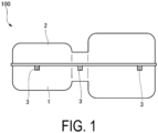
FIG. 1 is a schematic diagram illustrating a configuration of a casing unit according to a first embodiment of the present disclosure. -
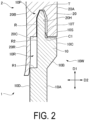
FIG. 2 is an enlarged cross-sectional view of a main part of the casing unit according to the first embodiment of the present disclosure. -
FIG. 3 is an explanatory view illustrating a state in the middle of assembling the casing unit according to the first embodiment of the present disclosure. -
FIG. 4 is an enlarged cross-sectional view of a main part illustrating a modification of the casing unit according to the first embodiment of the present disclosure. -
FIG. 5 is an enlarged cross-sectional view of a main part of a casing unit according to a second embodiment of the present disclosure. - Hereinafter, a
casing unit 100 according to the first embodiment of the present disclosure will be described with reference toFIGS. 1 to 3 . Thecasing unit 100 is a resin container that accommodates a fan, a heat exchanger, a damper, and the like of a vehicular air conditioning device, for example. As illustrated inFIG. 1 , thecasing unit 100 includes afirst casing 1 forming a lower half and asecond casing 2 forming an upper half and combined with thefirst casing 1. Thefirst casing 1 and thesecond casing 2 are provided with, inside therein, a space for accommodating the above-described various types of equipment and a flow path for guiding blowing. - The
first casing 1 and thesecond casing 2 are provided with a plurality ofengaging portions 3 for fixing them so as not to fall off from each other. In the following description, a direction in which thefirst casing 1 and thesecond casing 2 are combined is called a first direction D1. In the horizontal direction orthogonal to the first direction D1, a direction corresponding to the inner and outer directions of thecasing unit 100 is called a second direction D2. - Next, the configuration of a joint part of the
casing unit 100 will be described with reference toFIG. 2. FIG. 2 illustrates a cross section of a part different from theengaging portion 3 described above. As illustrated in the figure, thefirst casing 1 includes a first casingmain body 10, aprotrusion 10P, and atapered part 10T. - The first casing
main body 10 has afirst end surface 10S facing one side in the first direction D1, anouter surface 10W extending from an end edge of thefirst end surface 10S on one side in the second direction D2 toward the other side in the first direction D1, and aninner surface 10D facing a side opposite to theouter surface 10W in the second direction D2. - The
protrusion 10P is provided on thefirst end surface 10S. Theprotrusion 10P protrudes from thefirst end surface 10S toward one side in the first direction D1. The dimension (that is, the thickness) of theprotrusion 10P in the second direction D2 is set to be smaller than the dimension of thefirst end surface 10S in the second direction D2. - The
protrusion 10P has a base portion R and a tip portion T. Both surfaces of the base portion R in the second direction D2 extend parallel to the first direction D1. The tip portion T has a tapered cross-sectional shape where the dimension in the second direction D2 gradually decreases toward one side of the first direction D1. - The
tapered part 10T as a guiding part is formed between the base portion R of theprotrusion 10P and thefirst end surface 10S. Thetapered part 10T extends from a surface of the base portion R facing one side in the second direction D2 to thefirst end surface 10S. More specifically, thetapered part 10T has an end edge extending toward one side in the second direction D2 from the base portion R toward thefirst end surface 10S. A plurality of suchtapered parts 10T are provided at intervals over the entire extension length of theprotrusion 10P. - The
outer surface 10W has amain surface 10A, aninclined surface 10B, and aparallel surface 10C. Themain surface 10A and theparallel surface 10C extend in the first direction D1. Theinclined surface 10B extends obliquely toward one side in the second direction D2 from themain surface 10A toward theparallel surface 10C. Theseouter surfaces 10W are surfaces facing outward of thecasing unit 100. - The
inner surface 10D is a surface facing a side opposite to themain surface 10A, and is a surface facing the inside of thecasing unit 100. Theinner surface 10D is provided with arecess 10R in a part overlapping theinclined surface 10B and theparallel surface 10C in the first direction D1. Therecess 10R is recessed from theinner surface 10D toward one side in the second direction D2. - Specifically, the
recess 10R includes a bottom surface R1 facing one side in the first direction D1 and a side surface R2 connected to the bottom surface R1 and facing the other side in the second direction D2. The upper end of the side surface R2 is continuous with the base portion R of theprotrusion 10P. That is, no step or the like is formed between the base portion R and the side surface R2. - The
second casing 2 includes a second casingmain body 20 and an overlappingpart 20R. The second casingmain body 20 has a thickness substantially identical to the thickness (that is, the dimension in the second direction D2) from theparallel surface 10C to theinner surface 10D of the first casingmain body 10. The second casingmain body 20 has anouter surface 20A facing outward, aninner surface 20B facing inward, and asecond end surface 20C facing the other side in the first direction D1 (that is, facing thefirst casing 1 side). - The
second end surface 20C is provided with anaccommodating groove 20H in which the above-describedprotrusion 10P is accommodated. Theaccommodating groove 20H is recessed from thesecond end surface 20C toward one side in the first direction D1. The dimension of theaccommodating groove 20H in the second direction D2 is set to be slightly larger than the dimension of theprotrusion 10P in the second direction D2. In a state where thefirst casing 1 and thesecond casing 2 are combined, a gap is formed between an end surface on one side of theprotrusion 10P in the second direction D2 and theaccommodating groove 20H. On the other hand, the end surface on the other side of theprotrusion 10P and theaccommodating groove 20H are in a state of close contact with each other. At this time, a corner C1 between thesecond end surface 20C and theaccommodating groove 20H is in a state of contact with the above-describedtapered part 10T. - The overlapping
part 20R is provided on the other side of thesecond end surface 20C in the second direction D2. The overlappingpart 20R extends from thesecond end surface 20C toward the other side in the first direction D1. The thickness (that is, the dimension in the second direction D2) of the overlappingpart 20R is set to be smaller than the thickness of the second casingmain body 20. The length (that is, the dimension in the first direction D1) of the overlappingpart 20R is set to be larger than the length of theprotrusion 10P. In the state where thefirst casing 1 and thesecond casing 2 are combined, the overlappingpart 20R closes the above-describedrecess 10R from the other side in the second direction D2. At this time, the overlappingpart 20R is in a state of being elastically deformed so as to be slightly curved toward the other side in the second direction D2 with the connection part with thesecond end surface 20C as a fulcrum. That is, the overlappingpart 20R abuts on theinner surface 10D in a state where an elastic restoring force is applied. - Next, behavior of each part when the
casing unit 100 is assembled will be described with reference toFIG. 3 . As illustrated in the figure, in assembling thecasing unit 100, first, thefirst casing 1 and thesecond casing 2 face each other in the first direction D1. Next, thesecond casing 2 is moved in the first direction D1 with respect to thefirst casing 1, and theprotrusion 10P is brought into a state of being inserted halfway into theaccommodating groove 20H. At this time, the overlappingpart 20R is in a state of abutting on theinner surface 10D but not elastically deforming. - From the above state, the
second casing 2 is further moved in thefirst direction D 1. Then, the corner C1 of theaccommodating groove 20H abuts on thetapered part 10T. When thesecond casing 2 is still moved, the entiresecond casing 2 is moved toward one side in the second direction D2 by the corner C1 being guided by thetapered part 10T. That is, thesecond casing 2 moves relative to thefirst casing 1 in the second direction D2. Due to this, in a state where theentire protrusion 10P is accommodated in theaccommodating groove 20H, theprotrusion 10P and the inner surface of theaccommodating groove 20H are brought into close contact with each other as described on the basis ofFIG. 2 . At this time, since thesecond casing 2 has moved in the second direction D2, the overlappingpart 20R is brought into a state of elastically deforming while abutting on theinner surface 10D. - According to the above configuration, the
first casing 1 and thesecond casing 2 relatively move in the second direction D2 by thetapered part 10T serving as the guiding part, so that thefirst casing 1 and thesecond casing 2 are brought into a state of being strongly in close contact with each other. This can ensure higher airtightness and liquid tightness. In addition, since the overlappingpart 20R elastically deforms in a state of overlapping the first casingmain body 10, airtightness and liquid tightness can be further enhanced by the overlappingpart 20R. Since the part to be elastically deformed at the time of assembly is limited to only the overlappingpart 20R, assembly can be easily performed without requiring a large force. - Furthermore, according to the above configuration, since the dimension of the overlapping
part 20R is larger than that of theprotrusion 10P, the overlappingpart 20R can be more easily elastically deformed along with insertion of theprotrusion 10P. This makes it possible to perform assembly without requiring a large force. - According to the above configuration, when the
protrusion 10P is inserted into theaccommodating groove 20H, thesecond casing 2 relatively moves in the second direction D2 along thetapered part 10T. This makes it possible to cause thefirst casing 1 and thesecond casing 2 to be brought strongly into close contact with each other. By forming thetapered part 10T, it is possible to largely secure the base portion R (the part on the opposite side of the tip portion T) of theprotrusion 10P, and therefore it is also possible to enhance the strength of theprotrusion 10P. - The first embodiment of the present disclosure has been described above. Note that various changes and modifications can be made to the above-described configurations without departing from the gist of the present disclosure. For example, as illustrated in
FIG. 4 , it is also possible to adopt a configuration in which atapered part 10T' is formed over the entire region of the side surface of theprotrusion 10P facing the second direction D2, that is, the entire extension length of the base portion R. According to this configuration, it is possible to cause thefirst casing 1 and thesecond casing 2 to relatively move more largely by thetapered part 10T'. This makes it possible to cause thefirst casing 1 and thesecond casing 2 to be brought strongly into close contact with each other. - Next, a second embodiment of the present disclosure will be described with reference to
FIG. 5 . The same components as those of the first embodiment are denoted by the same reference signs, and detailed description thereof will be omitted. As illustrated in the figure, in the present embodiment, instead of the above-describedtapered part 10T, a guidingprojection 30 and a guidinggroove 30R as guiding parts are formed in thefirst casing 1 and thesecond casing 2, respectively. - The guiding
projection 30 protrudes from thesecond end surface 20C of thesecond casing 2 toward the other side in the first direction D1. The cross-sectional shape of the guidingprojection 30 is a right triangle. More specifically, the oblique side in the cross section of the guidingprojection 30 extends toward one side in the second direction D2 toward the other side in the first direction D1. - The guiding
groove 30R accommodates the guidingprojection 30. The guidinggroove 30R is recessed from thefirst end surface 10S of thefirst casing 1 toward the other side in the first direction D1. The cross-sectional shape of the guidinggroove 30R is the identical to the cross-sectional shape of the guidingprojection 30. The term "identical" mentioned here refers to being substantially identical and accounts for design tolerances and manufacturing errors. In a state where thefirst casing 1 and thesecond casing 2 face each other before they are combined, the guidinggroove 30R is formed at a position shifted to one side in the second direction D2 relative to the guidingprojection 30. The guidingprojection 30 and the guidinggroove 30R may be continuously formed over the entire circumference of thefirst end surface 10S and thesecond end surface 20C, or a plurality of them may be provided at intervals. - According to the above configuration, when the
protrusion 10P is inserted into theaccommodating groove 20H, the guidingprojection 30 is accommodated in the guidinggroove 30R. Here, the guidinggroove 30R is formed at a position shifted in the second direction D2 relative to the guidingprojection 30. Due to this, by the oblique sides of the guidingprojection 30 and the guidinggroove 30R abutting on each other in a sliding manner, it is possible to relatively move thefirst casing 1 and thesecond casing 2 in the second direction D2. As a result, it is possible to cause thefirst casing 1 and thesecond casing 2 to be brought strongly into close contact with each other. - The second embodiment of the present disclosure has been described above. Note that various changes and modifications can be made to the above-described configurations without departing from the gist of the present disclosure. For example, in the second embodiment, an example in which the
second casing 2 is provided with the guidingprojection 30 and thefirst casing 1 is provided with the guidinggroove 30R has been described. However, it is also possible to adopt a configuration in which thefirst casing 1 is provided with the guidingprojection 30 and thesecond casing 2 is provided with the guidinggroove 30R. Thetapered part 10T described in the first embodiment can also be applied in combination with the configuration of the second embodiment. - Unlike the above embodiments, the
casing unit 100 can also be used for accommodating mechanical devices other than the vehicular air conditioning device. The appearance of thecasing unit 100 illustrated inFIG. 1 is an example, and various shapes and dimensional sizes can be made in accordance with design and specifications. - The
casing unit 100 described in each embodiment is understood as follows, for example. - (1) The
casing unit 100 according to a first aspect is thecasing unit 100 including: thefirst casing 1; and thesecond casing 2 configured to be combined with thefirst casing 1 from the first direction D1, in which thefirst casing 1 includes the first casingmain body 10, and theprotrusion 10P that protrudes from the first casingmain body 10 toward thesecond casing 2, thesecond casing 2 includes the second casingmain body 20 provided with theaccommodating groove 20H that accommodates theprotrusion 10P, any one of theprotrusion 10P and the second casingmain body 20 is provided with a guiding part that relatively moves thefirst casing 1 and thesecond casing 2 in the second direction D2 intersecting the first direction D1, in response to combining thefirst casing 1 and thesecond casing 2 in the first direction D1, and thesecond casing 2 further includes the overlappingpart 20R that overlaps the first casingmain body 10 in the first direction D1 in the combined state, the overlapping part R being elastically deformable in response to thefirst casing 1 and thesecond casing 2 relatively moving in the second direction D2. - According to the above configuration, the
first casing 1 and thesecond casing 2 relatively move in the second direction D2 by the guiding part, so that thefirst casing 1 and thesecond casing 2 are brought into a state of being strongly in close contact with each other. Since the part to be elastically deformed at the time of assembly is limited to only the overlappingpart 20R, assembly can be easily performed without requiring a large force. - (2) In the
casing unit 100 according to a second aspect, the dimension of the overlappingpart 20R in the first direction D1 may be set to be larger than the dimension of theprotrusion 10P in the first direction D1. - According to the above configuration, since the dimension of the overlapping
part 20R is larger than that of theprotrusion 10P, the overlappingpart 20R can be more easily elastically deformed along with insertion of theprotrusion 10P. - (3) In the
casing unit 100 according to a third aspect, theprotrusion 10P may be formed on thefirst end surface 10S of the first casingmain body 10, thefirst end surface 10S facing the first direction D1, and, in a cross-sectional view orthogonal to the first direction D1, theprotrusion 10P may include the tip portion T extending in the first direction D1, and thetapered part 10T serving as the guiding part extending in the second direction D2 from the tip portion T toward thefirst end surface 10S. - According to the above configuration, when the
protrusion 10P is inserted into theaccommodating groove 20H, thesecond casing 2 relatively moves in the second direction D2 along thetapered part 10T. This makes it possible to cause thefirst casing 1 and thesecond casing 2 to be brought strongly into close contact with each other. - (4) In the
casing unit 100 according to a fourth aspect, thetapered part 10T' may be formed on the entire region of the surface of theprotrusion 10P facing the second direction D2. - According to the above configuration, it is possible to cause the
first casing 1 and thesecond casing 2 to relatively move more largely by thetapered part 10T'. - (5) In the
casing unit 100 according to a fifth aspect, theprotrusion 10P may be formed on thefirst end surface 10S of the first casingmain body 10, thefirst end surface 10S facing the first direction D1, theaccommodating groove 20H is formed on thesecond end surface 20C of the second casingmain body 20, thesecond end surface 20C opposing thefirst end surface 10S, and the guiding part includes the guidingprojection 30 protruding from any one of thefirst end surface 10S and thesecond end surface 20C toward the other of thefirst end surface 10S and thesecond end surface 20C, and the guidinggroove 30R formed in the other of thefirst end surface 10S and thesecond end surface 20C, accommodating the guidingprojection 30, and formed at a position shifted in the second direction D2 relative to the guidingprojection 30. - According to the above configuration, when the
protrusion 10P is inserted into theaccommodating groove 20H, the guidingprojection 30 is accommodated in the guidinggroove 30R. The guidinggroove 30R is formed at a position shifted in the second direction D2 relative to the guidingprojection 30. This makes it possible to relatively move thefirst casing 1 and thesecond casing 2 in the second direction D2. As a result, it is possible to cause thefirst casing 1 and thesecond casing 2 to be brought strongly into close contact with each other. - According to the present disclosure, it is possible to provide a casing unit that has higher airtightness and liquid tightness and can be easily assembled.
-
- 100 Casing unit
- 1 First casing
- 2 Second casing
- 3 Engaging portion
- 10 First casing main body
- 10A Main surface
- 10B Inclined surface
- 10C Parallel surface
- 10D Inner surface
- 10P Protrusion
- 10R Recess
- 10S First end surface
- 10T, 10T' Tapered part
- 10W Outer surface
- 20 Second casing main body
- 20A Outer surface
- 20B Inner surface
- 20C Second end surface
- 20H Accommodating groove
- 20R Overlapping part
- 30 Guiding projection
- 30R Guiding groove
- C1 Corner
- R Base portion
- R1 Bottom surface
- R2 Side surface
- T Tip portion
Claims (5)
- A casing unit comprising:a first casing; anda second casing configured to be combined with the first casing from a first direction, whereinthe first casing includesa first casing main body, anda protrusion that protrudes from the first casing main body toward the second casing,the second casing includesa second casing main body provided with an accommodating groove that accommodates the protrusion,any one of the protrusion and the second casing main body is provided with a guiding part that relatively moves the first casing and the second casing in a second direction intersecting the first direction, in response to combining the first casing and the second casing in the first direction, andthe second casing further includes an overlapping part that overlaps the first casing main body in the first direction in the combined state, the overlapping part being elastically deformable in response to the first casing and the second casing relatively moving in the second direction.
- The casing unit according to claim 1, wherein a dimension of the overlapping part in the first direction is set to be larger than a dimension of the protrusion in the first direction.
- The casing unit according to claim 1 or 2, whereinthe protrusion is formed on a first end surface of the first casing main body, the first end surface facing the first direction, andin a cross-sectional view orthogonal to the first direction, the protrusion includes a tip portion extending in the first direction, and a tapered part serving as the guiding part extending in the second direction from the tip portion toward the first end surface.
- The casing unit according to claim 3, wherein the tapered part is formed on an entire region of a surface of the protrusion facing the second direction.
- The casing unit according to any one of claims 1 to 4, whereinthe protrusion is formed on a first end surface of the first casing main body, the first end surface facing the first direction,the accommodating groove is formed on a second end surface of the second casing main body, the second end surface opposing the first end surface, andthe guiding part includesa guiding projection protruding from any one of the first end surface and the second end surface toward the other of the first end surface and the second end surface, anda guiding groove formed in the other of the first end surface and the second end surface, accommodating the guiding projection and formed at a position shifted in the second direction relative to the guiding projection.
Applications Claiming Priority (2)
| Application Number | Priority Date | Filing Date | Title |
|---|---|---|---|
| JP2020208378A JP7657046B2 (en) | 2020-12-16 | 2020-12-16 | Casing Unit |
| PCT/JP2021/043199 WO2022130927A1 (en) | 2020-12-16 | 2021-11-25 | Casing unit |
Publications (2)
| Publication Number | Publication Date |
|---|---|
| EP4234284A1 true EP4234284A1 (en) | 2023-08-30 |
| EP4234284A4 EP4234284A4 (en) | 2024-05-08 |
Family
ID=82059081
Family Applications (1)
| Application Number | Title | Priority Date | Filing Date |
|---|---|---|---|
| EP21906290.8A Withdrawn EP4234284A4 (en) | 2020-12-16 | 2021-11-25 | HOUSING UNIT |
Country Status (5)
| Country | Link |
|---|---|
| US (1) | US20230391162A1 (en) |
| EP (1) | EP4234284A4 (en) |
| JP (1) | JP7657046B2 (en) |
| CN (1) | CN116529101A (en) |
| WO (1) | WO2022130927A1 (en) |
Families Citing this family (3)
| Publication number | Priority date | Publication date | Assignee | Title |
|---|---|---|---|---|
| CN217022121U (en) * | 2022-01-20 | 2022-07-22 | 多美达瑞典有限公司 | Overhead unit for air conditioner of vehicle and air conditioner including the same |
| CN119365418A (en) | 2022-06-13 | 2025-01-24 | Agc株式会社 | Process for producing spherical silica powder |
| JP2025144995A (en) * | 2024-03-21 | 2025-10-03 | パナソニックIpマネジメント株式会社 | Outdoor units for air conditioning systems |
Family Cites Families (10)
| Publication number | Priority date | Publication date | Assignee | Title |
|---|---|---|---|---|
| FR2568196B1 (en) * | 1984-07-24 | 1988-09-02 | Chausson Usines Sa | CONNECTION DEVICE FOR HOUSING - SHAPED ELEMENTS AND ITS APPLICATION TO THE PRODUCTION OF HOUSINGS FOR VEHICLE AIR CONDITIONERS. |
| ES2036010T3 (en) * | 1989-08-31 | 1993-05-01 | Siemens Aktiengesellschaft | HERMETICALLY MOUNTABLE CASING CONSTITUTED BY AT LEAST TWO PARTS OF CASING. |
| US5248849A (en) * | 1989-11-15 | 1993-09-28 | Modelec S.A. | Spray-protected connection housing for electrical consumers |
| JP4600338B2 (en) * | 2005-11-09 | 2010-12-15 | 株式会社デンソー | Air conditioner |
| JP5601858B2 (en) * | 2010-03-25 | 2014-10-08 | 三菱重工業株式会社 | Air conditioner for vehicles |
| JP5627296B2 (en) * | 2010-05-31 | 2014-11-19 | 三菱重工業株式会社 | Air conditioner for vehicles |
| DE102011089092A1 (en) * | 2011-12-19 | 2013-06-20 | Behr Gmbh & Co. Kg | Housing in particular for a motor vehicle air conditioning system |
| US9061566B2 (en) | 2012-10-25 | 2015-06-23 | Delphi Technologies, Inc. | HVAC case having equalized sealing force tongue and groove joint |
| JP5949448B2 (en) * | 2012-10-29 | 2016-07-06 | 株式会社デンソー | Air conditioning case |
| JP2018177198A (en) | 2017-04-17 | 2018-11-15 | 株式会社デンソー | Air conditioning case |
-
2020
- 2020-12-16 JP JP2020208378A patent/JP7657046B2/en active Active
-
2021
- 2021-11-25 CN CN202180081197.4A patent/CN116529101A/en not_active Withdrawn
- 2021-11-25 EP EP21906290.8A patent/EP4234284A4/en not_active Withdrawn
- 2021-11-25 US US18/266,949 patent/US20230391162A1/en active Pending
- 2021-11-25 WO PCT/JP2021/043199 patent/WO2022130927A1/en not_active Ceased
Also Published As
| Publication number | Publication date |
|---|---|
| JP7657046B2 (en) | 2025-04-04 |
| WO2022130927A1 (en) | 2022-06-23 |
| EP4234284A4 (en) | 2024-05-08 |
| US20230391162A1 (en) | 2023-12-07 |
| JP2022095197A (en) | 2022-06-28 |
| CN116529101A (en) | 2023-08-01 |
Similar Documents
| Publication | Publication Date | Title |
|---|---|---|
| US20230391162A1 (en) | Casing unit | |
| US10050391B2 (en) | Holding frame for a plug connector | |
| CN102844949B (en) | For the protective ring of wire harness | |
| US6343953B2 (en) | Structure for assembling a housing and a connector | |
| JP6544412B2 (en) | Connector terminals and connectors | |
| JP5095372B2 (en) | Wiring / Piping material protection cover | |
| KR20140032874A (en) | Electronic device unit and electronic device | |
| JP2000104635A (en) | Suction resonator of automobile | |
| US20120048693A1 (en) | Mode Switch For Vehicle | |
| US9022817B2 (en) | Connector terminal including limiter extending along first and second spring terminals | |
| US10153578B2 (en) | Connector structure | |
| JP6125149B2 (en) | Wind direction adjusting plate, air conditioner, and method of manufacturing wind direction adjusting plate | |
| JP5676302B2 (en) | Drawer connector | |
| JP2012122518A (en) | Gasket | |
| KR20190051791A (en) | Connector assembly and method of manufacturing thereof | |
| CN110854766B (en) | Locking structure, electrical connection box and wiring harness | |
| EP3030063A1 (en) | Housing for electronic control unit | |
| KR200430659Y1 (en) | Receptacle Terminal | |
| CN220096291U (en) | A connection structure between side decorative strips and side decorative panels | |
| JP6105382B2 (en) | Lock structure | |
| US20260043475A1 (en) | Sealing structure of vehicle component | |
| CN105357922A (en) | Housing and electronic device | |
| JP2019054094A (en) | Housing connection structure | |
| JP2000193092A (en) | Packing | |
| US9418813B2 (en) | Fuse assembly |
Legal Events
| Date | Code | Title | Description |
|---|---|---|---|
| STAA | Information on the status of an ep patent application or granted ep patent |
Free format text: STATUS: THE INTERNATIONAL PUBLICATION HAS BEEN MADE |
|
| PUAI | Public reference made under article 153(3) epc to a published international application that has entered the european phase |
Free format text: ORIGINAL CODE: 0009012 |
|
| STAA | Information on the status of an ep patent application or granted ep patent |
Free format text: STATUS: REQUEST FOR EXAMINATION WAS MADE |
|
| 17P | Request for examination filed |
Effective date: 20230525 |
|
| AK | Designated contracting states |
Kind code of ref document: A1 Designated state(s): AL AT BE BG CH CY CZ DE DK EE ES FI FR GB GR HR HU IE IS IT LI LT LU LV MC MK MT NL NO PL PT RO RS SE SI SK SM TR |
|
| DAV | Request for validation of the european patent (deleted) | ||
| DAX | Request for extension of the european patent (deleted) | ||
| A4 | Supplementary search report drawn up and despatched |
Effective date: 20240408 |
|
| RIC1 | Information provided on ipc code assigned before grant |
Ipc: F24F 13/20 20060101ALI20240402BHEP Ipc: B60H 1/32 20060101ALI20240402BHEP Ipc: B60H 1/00 20060101AFI20240402BHEP |
|
| GRAP | Despatch of communication of intention to grant a patent |
Free format text: ORIGINAL CODE: EPIDOSNIGR1 |
|
| STAA | Information on the status of an ep patent application or granted ep patent |
Free format text: STATUS: GRANT OF PATENT IS INTENDED |
|
| RIC1 | Information provided on ipc code assigned before grant |
Ipc: F24F 13/20 20060101ALI20250218BHEP Ipc: B60H 1/00 20060101AFI20250218BHEP |
|
| INTG | Intention to grant announced |
Effective date: 20250227 |
|
| STAA | Information on the status of an ep patent application or granted ep patent |
Free format text: STATUS: THE APPLICATION IS DEEMED TO BE WITHDRAWN |
|
| 18D | Application deemed to be withdrawn |
Effective date: 20250628 |