EP4234278A1 - Tire - Google Patents
Tire Download PDFInfo
- Publication number
- EP4234278A1 EP4234278A1 EP22215014.6A EP22215014A EP4234278A1 EP 4234278 A1 EP4234278 A1 EP 4234278A1 EP 22215014 A EP22215014 A EP 22215014A EP 4234278 A1 EP4234278 A1 EP 4234278A1
- Authority
- EP
- European Patent Office
- Prior art keywords
- region
- shadow region
- shadow
- concave
- tire
- Prior art date
- Legal status (The legal status is an assumption and is not a legal conclusion. Google has not performed a legal analysis and makes no representation as to the accuracy of the status listed.)
- Granted
Links
Images


Classifications
-
- B—PERFORMING OPERATIONS; TRANSPORTING
- B60—VEHICLES IN GENERAL
- B60C—VEHICLE TYRES; TYRE INFLATION; TYRE CHANGING; CONNECTING VALVES TO INFLATABLE ELASTIC BODIES IN GENERAL; DEVICES OR ARRANGEMENTS RELATED TO TYRES
- B60C13/00—Tyre sidewalls; Protecting, decorating, marking, or the like, thereof
- B60C13/001—Decorating, marking or the like
Definitions
- the present invention relates to a tire.
- Patent Literature 1 Japanese Unexamined Patent Application Publication No. 2020-125045 has proposed a tire having a sidewall portion provided with concave marks.
- a bottom surface of each of the concave marks includes a shadow region which is a part of the bottom surface in shadow of a wall of the concave mark, and the shadow region has a plurality of minute protuberances.
- the minute protuberances configured as such provide contrast to the bottom surfaces of the concave marks, and thus improve the visibility of the concave marks.
- the present invention was made in view of the above, and a primary object thereof is to provide a tire capable of exerting excellent visibility of the concave marks on the sidewall portions.
- the present invention is a tire including a pair of sidewall portions, wherein
- the tire of the present invention can exert excellent visibility with respect to the concave marks on the sidewall portions by adopting the above configuration.
- FIG. 1 is an enlarged perspective view of one of sidewall portions 3 of a tire 1 according to one embodiment of the present invention.
- the tire 1 of the present invention has a pair of the sidewall portions 3 and FIG. 1 shows a portion of an outer surface of one of the sidewall portions 3.
- the tire 1 of the present invention is used as a pneumatic tire for passenger cars, for example.
- the present invention may be applied to motorcycle tires and heavy-duty tires, for example.
- each of the sidewall portions 3 have a visible outer surface (3s).
- the visible outer surface (3s) is the surface visible from the outside when the tire is in use.
- At least one of the outer surfaces (3s) of the pair of the sidewall portions 3 includes at least one concave mark 5 recessed from a reference surface (3c).
- a reference surface (3c) is a portion of the outer surface (3s) around the at least one concave mark 5.
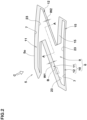
- FIG. 2 shows an enlarged plan view of one of the concave marks 5 of FIG. 1 .
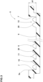
- FIG. 3 shows an A-A cross-section of the concave mark 5 of FIG. 2 .
- each of the concave marks 5 includes a bottom surface 6 and an inner wall surface 7 extending in a depth direction of the concave mark 5 to surround the bottom surface 6.
- a depth (d1) of each of the concave marks 5 is, for example, 1.5 mm or less, preferably 1.0 mm or less, and more preferably from 0.4 to 0.7 mm.
- standard state refers to a state in which the tire is mounted on a standard rim, inflated to a standard inner pressure, and loaded with no tire load.
- the standard state means a state of standard use according to the purpose of use of the tire and being loaded with no tire load.
- standard rim refers to a wheel rim specified for the concerned tire by a standard included in a standardization system on which the tire is based, for example, the "normal wheel rim” in JATMA, "Design Rim” in TRA, and “Measuring Rim” in ETRTO.
- standard inner pressure refers to air pressure specified for the concerned tire by a standard included in a standardization system on which the tire is based, for example, the maximum air pressure in JATMA, maximum value listed in the "TIRE LOAD LIMITS AT VARIOUS COLD INFLATION PRESSURES" table in TRA, and "INFLATION PRESSURE” in ETRTO.
- each of the concave marks 5 has a contour (5o) thereof composed by the inner wall surface 7.
- the bottom surface 6 and the inner wall surface 7 have a light contrast to increase the visibility of the concave mark 5 when a user observes the tire. It should be noted that in the present specification, when a user observes the tire means when the user observes the sidewall portions 3 of the tire 1 mounted on the vehicle staying still.
- the bottom surface 6 includes a peripheral region 10 extending along the contour (5o) of the concave mark 5 and a main region 9 surrounded by the peripheral region 10.
- the peripheral region 10 includes a shadow region 11 and a non-shadow region 12.
- the shadow region 11 is a region where the shadow of the inner wall surface 7 is formed when light is assumed to be shed to the concave mark 5 from a first direction.
- the non-shadow region 12 is the region where the shadow of the inner wall surface 7 is not formed in the above assumption.
- the shadow region 11 and the non-shadow region 12 are shaded and conceptually shown for easy understanding of the contents of the present invention.
- the first direction means any one direction, and in the present embodiment, the direction of an arrow C, which extends from the upper left diagonal position to the lower right diagonal position, corresponds to the first direction.
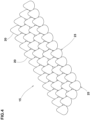
- FIG. 4 is an enlarged perspective view of a region B of FIG. 2 conceptually showing the uneven surfaces 15.
- the uneven surfaces 15 are provided with a plurality of minute protuberances 20 to disperse and reflect light in multiple directions. Therefore, the uneven surfaces 15 are observed as regions with a high degree of blackness when a user observes the tire, and thus the contrast with other portions can be enhanced.
- the uneven surface 15 of the non-shadow region 12 has a width W2 smaller than a width W1 of the uneven surfaces 15 of the shadow region 11.
- each of the width W1 and the width W2 means a width measured in the direction perpendicular to the contour (5o) of the concave mark 5 in a respective one of the shadow region 11 and the non-shadow region 12.
- the positions of the concave marks in the tire rotational direction are various at the time of observation of the tire. Therefore, it is assumed that the concave marks are exposed to light from various directions.
- the concave mark is at the 12 o'clock position
- light is shed from a direction opposite to when the concave mark is positioned at the lowest point in the tire radial direction (hereinafter, such a state may be referred to as "the concave mark is at the 6 o'clock position").
- conventional concave marks may impair visibility and stereoscopic effect depending on the direction of light. For this reason, for example, even if the concave mark at the 12 o'clock position exhibits relatively high visibility, the contour of the concave mark at the 6 o'clock position may be difficult to see or the three-dimensional effect may be impaired.
- the shadow regions 11 and the non-shadow regions 12 of the concave marks 5 are formed by the uneven surfaces 15 on which multiple minute protuberances 20 are arranged, and the width W2 of each of the non-shadow regions 12 is smaller than the width W1 of each of the shadow regions 11.
- the contours (5o) of the concave marks 5 are easily recognized no matter what direction the light hits the concave marks 5.
- the above-mentioned shadow regions 11 and the non-shadow regions 12 give the impression that light is emitted from a specific direction (the first direction described above), therefore, three-dimensional effect is given to the concave marks 5.
- the tire 1 of the present invention can exert excellent visibility of the concave marks 5 of the sidewall portions 3.
- the visibility of the concave marks 5 can be increased without increasing the depth (d1) (shown in FIG. 3 ) of each of the concave marks 5. Therefore, the depth (d1) can be set to be smaller than the conventional one, thereby, an improvement in durability of the tire can be expected. In addition, by setting the depth (d1) to be small, the air resistance that the sidewall portions 3 receive when the tire 1 rotates becomes small, thereby, a reduction in rolling resistance of the tire can also be expected.
- the main region 9 of the bottom surface 6 and the inner wall surface 7 of the present embodiment are not provided with the minute protuberances 20 and consist of flat surfaces. Therefore, the contrast with the uneven surfaces 15 is increased, thereby, the visibility is improved.
- each of the concave marks 5 is not limited to such a mode, and the main region 9 and the inner wall surface 7 may be provided with the minute protuberances 20 so as to create contrast with the peripheral region 10.
- the uneven surface 15 is formed over the entire area where the shadow of the inner wall surface 7 is formed.
- the present invention is not limited to such an embodiment, and the uneven surface 15 may be formed in part of the area where the shadow of the inner wall surface 7 is formed.
- the width W1 of the uneven surface 15 of the shadow region 11 in a longitudinal direction of the contour (5o) the more the three-dimensional effect of the concave mark 5 can be enhanced. Therefore, it is preferred that a difference between a maximum value and a minimum value of the width W1 is 20% or less of the maximum value.
- the width W1 is substantially constant in the longitudinal direction of the contour (5o). Moreover, it is preferred that the width W1 is from 5% to 15% of a length L1 (shown in FIG. 1 ) in the tire radial direction of each of the concave marks 5.
- the uneven surface 15 having the width W2 is formed preferably in 50% or more and more preferably in 80% or more of a total length of the non-shadow region 12 (which is the length along the contour (5o)).
- substantially the entire non-shadow region 12 is formed by the uneven surface 15 having the width W2.
- the width W2 is substantially constant in the longitudinal direction of the contour (5o).
- the width W2 of the uneven surface 15 of the non-shadow region 12 is, for example, from 20% to 70%, and preferably from 30% to 50% of the width W1 of the uneven surface 15 of the shadow region 11.
- the shape of the minute protuberances 20 is not limited as long as the uneven surfaces 15 can exert the effect of dispersing and reflecting light. As shown in FIG. 4 , in a preferred embodiment, the minute protuberances 20 are of the same size and the same shape.
- FIG. 5 shows an enlarged cross-sectional view of one of the minute protuberances 20 of the present embodiment.
- each of the minute protuberances 20 in the present embodiment has a conical shape with a rounded apex 21, for example.
- each of the multiple minute protuberances 20 has a circular contour.
- Each of the minute protuberances 20 has a diameter D1 of 0.2 mm or more and 0.6 mm or less, preferably 0.3 mm or more and 0.5 mm or less, for example. It should be noted that the diameter D1 means the diameter of the root portion (bottom) of each of the minute protuberances 20.
- Each of the minute protuberances 20 has a height (h1) of 0.2 mm or more and 0.6 mm or less, preferably 0.3 mm or more and 0.5 mm or less, for example.
- the average number of the minute protuberances 20 per 1 sq.mm is from 2 to 8, for example. However, the present invention is not limited to such an aspect.
- FIG. 6 shows an enlarged cross-sectional view of one of the minute protuberances 20 according to another embodiment of the present invention. As shown in FIG. 6 , in this embodiment, a minute recess 22 is formed in the apex 21 of each of the minute protuberances 20.
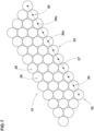
- FIG. 7 is an enlarged plan view of the region B in FIG. 2 , showing the arrangement of the minute protuberances 20 in a front view of the concave marks 5.
- each of the shadow region 11 and the non-shadow region 12 includes a region in which the minute protuberances 20 are arranged in closest packing.
- the minute protuberances 20 are arranged in close packing in 80% or more of the shadow region 11 and the non-shadow region 12. Therefore, the blackness of the shadow region 11 and the non-shadow region 12 is further increased, thereby, the visibility of the concave marks 5 is improved.
- the peripheral region 10 includes a boundary 23 between the uneven surface 15 and the area where the minute protuberances 20 are not arranged.
- each of the shadow region 11 and the non-shadow region 12 includes a boundary protuberance row 25 in which the minute protuberances 20 are arranged to form the boundary 23.
- the minute protuberances 20 are arranged in the boundary protuberance row 25 so that the contours of the minute protuberances 20 are in contact with each other.
- a virtual line 27 connecting centroids (20c) of the contours of the minute protuberances 20 included in the boundary protuberance row 25 has a non-zigzag shape without containing any bends at an angle of 120 degrees or less.
- the boundary protuberance row 25 configured as such allows the boundary 23 to be closer to a straight line, which helps to further increase the contrast between the uneven surfaces 15 and the area where the minute protuberances 20 are not arranged.
- each of the minute protuberances 20 has a circular contour, and in each of the minute protuberances 20, the centroid (20c) corresponds to the center of the circular contour.
- the virtual line 27 is bent, it is preferred that the virtual line 27 is bent at an angle of 150 degrees or more. Further, in a more preferred embodiment, the virtual line 27 is a straight line. Thereby, the above-described effect can be further enhanced.
- Tires of size 245/40ZR18 having the concave marks of FIG. 1 were made by way of test according to the specifications listed in Table 1. Further, as Reference, a tire was made in which the uneven surface was formed in the shadow region but the uneven surface was not formed in the non-shadow region. The tire in the Reference is substantially the same as the tire shown in FIG. 1 , except for the above. As the visibility, the visibility of the concave mark at the 12 o'clock position and the 6 o'clock position and the three-dimensional effect of the concave mark were tested for each of the test tires. Common specifications and test methods for the test tires are as follows.
- Each of the test tires was mounted on a vehicle, and the visibility of the concave marks (mainly the clarity of the contours of the concave marks) were evaluated when the concave marks were at the 12 o'clock position and the 6 o'clock position. The results are indicated by an evaluation point based on the visibility of the Reference being 100, wherein the larger the numerical value, the better the visibility is at the respective position.
- Rectangular (40 ⁇ 200 mm) rubber samples containing the concave marks were cut from the tires, and the three-dimensional effect was evaluated comprehensively when the concave marks were observed from various directions. The results are indicated by an evaluation point based on the three-dimensional effect of the Reference being 100, wherein the larger the numerical value, the better the three-dimensional effect is.
- the present invention includes the following aspects.
- a tire including a pair of sidewall portions, wherein
- width (W2) of the uneven surface of the non-shadow region is 20% or more and 70% or less of the width (W1) of the uneven surface of the shadow region.
Landscapes
- Engineering & Computer Science (AREA)
- Mechanical Engineering (AREA)
- Tires In General (AREA)
Abstract
Description
- This application claims the benefit of foreign priority to Japanese Patent Applications No.
JP2022-026993, filed February 24, 2022 - The present invention relates to a tire.
-
Japanese Unexamined Patent Application Publication No. 2020-125045 - In recent years, there has been a demand for further improvement in the visibility of concave marks on tire sidewalls. In particular, in the concave marks of
Patent Literature 1, it was sometimes difficult to visually recognize the entire contour of each of the concave marks depending on the direction of light (viewing direction). - The present invention was made in view of the above, and a primary object thereof is to provide a tire capable of exerting excellent visibility of the concave marks on the sidewall portions.
- The present invention is a tire including a pair of sidewall portions, wherein
- an outer surface of at least one of the sidewall portions includes at least one concave mark recessed from a reference surface,
- the or each concave mark includes a bottom surface and an inner wall surface extending in a depth direction of the or each concave mark to surround the bottom surface,
- the bottom surface includes a peripheral region extending along a contour of the or each concave mark and a main region surrounded by the peripheral region,
- the peripheral region includes a shadow region and a non-shadow region,
- the shadow region is a region where the shadow of the inner wall surface is formed when light is assumed to be shed to the or each concave mark from a first direction,
- the non-shadow region is a region where the shadow of the inner wall surface is not formed when light is assumed to be shed to the or each concave mark from the first direction,
- each of the shadow region and the non-shadow region is formed with an uneven surface provided with a plurality of minute protuberances, and
- a width (W2) of the uneven surface of the non-shadow region measured in a direction perpendicular to the contour is smaller than a width (W1) of the uneven surface of the shadow region measured in a direction perpendicular to the contour.
- The tire of the present invention can exert excellent visibility with respect to the concave marks on the sidewall portions by adopting the above configuration.
-
-
FIG. 1 is an enlarged perspective view of a sidewall portion of a tire according to the present embodiment. -
FIG. 2 is an enlarged plan view of one of the concave marks ofFIG. 1 . -
FIG. 3 is an A-A cross sectional view ofFIG. 2 . -
FIG. 4 is an enlarged perspective view of a region B ofFIG. 2 . -
FIG. 5 is an enlarged cross-sectional view of one of minute protuberances of the present embodiment. -
FIG. 6 is an enlarged cross-sectional view of one of the minute protuberances of another embodiment. -
FIG. 7 is an enlarged plan view of the region B ofFIG. 2 . - An embodiment of the present invention will now be described below in conjunction with accompanying drawings.
FIG. 1 is an enlarged perspective view of one ofsidewall portions 3 of atire 1 according to one embodiment of the present invention. Thetire 1 of the present invention has a pair of thesidewall portions 3 andFIG. 1 shows a portion of an outer surface of one of thesidewall portions 3. As shown inFIG. 1 , thetire 1 of the present invention is used as a pneumatic tire for passenger cars, for example. The present invention may be applied to motorcycle tires and heavy-duty tires, for example. - As shown in
FIG. 1 , each of thesidewall portions 3 have a visible outer surface (3s). The visible outer surface (3s) is the surface visible from the outside when the tire is in use. At least one of the outer surfaces (3s) of the pair of thesidewall portions 3 includes at least oneconcave mark 5 recessed from a reference surface (3c). Although "Z", "E", and "N" are described as theconcave marks 5 inFIG. 1 , the present invention is not limited to such embodiments. It should be noted that the reference surface (3c) is a portion of the outer surface (3s) around the at least oneconcave mark 5. -
FIG. 2 shows an enlarged plan view of one of theconcave marks 5 ofFIG. 1 .FIG. 3 shows an A-A cross-section of theconcave mark 5 ofFIG. 2 . As shown inFIGs. 2 and3 , each of theconcave marks 5 includes abottom surface 6 and aninner wall surface 7 extending in a depth direction of theconcave mark 5 to surround thebottom surface 6. As shown inFIG. 3 , a depth (d1) of each of theconcave marks 5 is, for example, 1.5 mm or less, preferably 1.0 mm or less, and more preferably from 0.4 to 0.7 mm. - It should be noted that in the present specification, unless otherwise specified, dimensions of various parts of the tire are measured with the tire in a standard state. In the case of a pneumatic tire for which various standards are specified, the term "standard state" refers to a state in which the tire is mounted on a standard rim, inflated to a standard inner pressure, and loaded with no tire load. In the case of tires for which various standards have not been established, the standard state means a state of standard use according to the purpose of use of the tire and being loaded with no tire load.
- The term "standard rim" refers to a wheel rim specified for the concerned tire by a standard included in a standardization system on which the tire is based, for example, the "normal wheel rim" in JATMA, "Design Rim" in TRA, and "Measuring Rim" in ETRTO.
- The term "standard inner pressure" refers to air pressure specified for the concerned tire by a standard included in a standardization system on which the tire is based, for example, the maximum air pressure in JATMA, maximum value listed in the "TIRE LOAD LIMITS AT VARIOUS COLD INFLATION PRESSURES" table in TRA, and "INFLATION PRESSURE" in ETRTO.
- As shown in
FIG. 2 , each of theconcave marks 5 has a contour (5o) thereof composed by theinner wall surface 7. Thebottom surface 6 and theinner wall surface 7 have a light contrast to increase the visibility of theconcave mark 5 when a user observes the tire. It should be noted that in the present specification, when a user observes the tire means when the user observes thesidewall portions 3 of thetire 1 mounted on the vehicle staying still. - The
bottom surface 6 includes aperipheral region 10 extending along the contour (5o) of theconcave mark 5 and amain region 9 surrounded by theperipheral region 10. Theperipheral region 10 includes ashadow region 11 and anon-shadow region 12. Theshadow region 11 is a region where the shadow of theinner wall surface 7 is formed when light is assumed to be shed to theconcave mark 5 from a first direction. Thenon-shadow region 12 is the region where the shadow of theinner wall surface 7 is not formed in the above assumption. InFIG. 2 , theshadow region 11 and thenon-shadow region 12 are shaded and conceptually shown for easy understanding of the contents of the present invention. Further, the first direction means any one direction, and in the present embodiment, the direction of an arrow C, which extends from the upper left diagonal position to the lower right diagonal position, corresponds to the first direction. - The
shadow region 11 and thenon-shadow region 12 are formed byuneven surfaces 15.FIG. 4 is an enlarged perspective view of a region B ofFIG. 2 conceptually showing theuneven surfaces 15. As shown inFIG. 4 , theuneven surfaces 15 are provided with a plurality ofminute protuberances 20 to disperse and reflect light in multiple directions. Therefore, theuneven surfaces 15 are observed as regions with a high degree of blackness when a user observes the tire, and thus the contrast with other portions can be enhanced. - As shown in
FIG. 2 , in the present invention, theuneven surface 15 of thenon-shadow region 12 has a width W2 smaller than a width W1 of theuneven surfaces 15 of theshadow region 11. It should be noted that each of the width W1 and the width W2 means a width measured in the direction perpendicular to the contour (5o) of theconcave mark 5 in a respective one of theshadow region 11 and thenon-shadow region 12. By adopting the above configuration, the tire of the present invention can exert excellent visibility of theconcave marks 5 of thesidewall portions 3. The mechanism is as follows. - In general, the positions of the concave marks in the tire rotational direction are various at the time of observation of the tire. Therefore, it is assumed that the concave marks are exposed to light from various directions. For example, at the time of tire observation, when the concave mark is located at the highest point in a tire radial direction (hereinafter, such a state may be referred to as "the concave mark is at the 12 o'clock position"), light is shed from a direction opposite to when the concave mark is positioned at the lowest point in the tire radial direction (hereinafter, such a state may be referred to as "the concave mark is at the 6 o'clock position").
- On the other hand, conventional concave marks may impair visibility and stereoscopic effect depending on the direction of light. For this reason, for example, even if the concave mark at the 12 o'clock position exhibits relatively high visibility, the contour of the concave mark at the 6 o'clock position may be difficult to see or the three-dimensional effect may be impaired.
- In contrast, in the present invention, the
shadow regions 11 and thenon-shadow regions 12 of theconcave marks 5 are formed by theuneven surfaces 15 on whichmultiple minute protuberances 20 are arranged, and the width W2 of each of thenon-shadow regions 12 is smaller than the width W1 of each of theshadow regions 11. Thereby, the contours (5o) of theconcave marks 5 are easily recognized no matter what direction the light hits theconcave marks 5. Further, regardless of the position of theconcave marks 5 in the tire rotational direction, the above-mentionedshadow regions 11 and thenon-shadow regions 12 give the impression that light is emitted from a specific direction (the first direction described above), therefore, three-dimensional effect is given to theconcave marks 5. By such a mechanism, thetire 1 of the present invention can exert excellent visibility of theconcave marks 5 of thesidewall portions 3. - As described above, in the present invention, the visibility of the
concave marks 5 can be increased without increasing the depth (d1) (shown inFIG. 3 ) of each of theconcave marks 5. Therefore, the depth (d1) can be set to be smaller than the conventional one, thereby, an improvement in durability of the tire can be expected. In addition, by setting the depth (d1) to be small, the air resistance that thesidewall portions 3 receive when thetire 1 rotates becomes small, thereby, a reduction in rolling resistance of the tire can also be expected. - A more detailed configuration of the present embodiment will be described below. It should be noted that each configuration described below represents a specific aspect of the present embodiment. Therefore, it goes without saying that the present invention can achieve the effects described above even if it does not have the configuration described below. Further, even if any one of the configurations described below is applied alone to the tire of the present invention having the features described above, an improvement in performance according to each configuration can be expected. Furthermore, when some of the configurations described below are applied in combination, a combined improvement in performance can be expected according to the combination.
- As shown in
FIGs. 2 and3 , themain region 9 of thebottom surface 6 and theinner wall surface 7 of the present embodiment are not provided with theminute protuberances 20 and consist of flat surfaces. Therefore, the contrast with theuneven surfaces 15 is increased, thereby, the visibility is improved. However, each of theconcave marks 5 is not limited to such a mode, and themain region 9 and theinner wall surface 7 may be provided with theminute protuberances 20 so as to create contrast with theperipheral region 10. - As shown in
FIG. 2 , in the present embodiment, as a preferred aspect, when it is assumed that light is applied to each of theconcave marks 5 from the first direction, preferably 50% or more, more preferably 80% or more of the area where the shadow of theinner wall surface 7 is provided with theuneven surface 15. As a further preferred aspect, in the present embodiment, theuneven surface 15 is formed over the entire area where the shadow of theinner wall surface 7 is formed. However, the present invention is not limited to such an embodiment, and theuneven surface 15 may be formed in part of the area where the shadow of theinner wall surface 7 is formed. - The smaller the change of the width W1 of the
uneven surface 15 of theshadow region 11 in a longitudinal direction of the contour (5o), the more the three-dimensional effect of theconcave mark 5 can be enhanced. Therefore, it is preferred that a difference between a maximum value and a minimum value of the width W1 is 20% or less of the maximum value. As a more preferred aspect, in the present embodiment, the width W1 is substantially constant in the longitudinal direction of the contour (5o). Moreover, it is preferred that the width W1 is from 5% to 15% of a length L1 (shown inFIG. 1 ) in the tire radial direction of each of theconcave marks 5. - In order to reliably improve the visibility, the
uneven surface 15 having the width W2 is formed preferably in 50% or more and more preferably in 80% or more of a total length of the non-shadow region 12 (which is the length along the contour (5o)). In the present embodiment, substantially the entirenon-shadow region 12 is formed by theuneven surface 15 having the width W2. - Regarding the
uneven surface 15 of thenon-shadow region 12, the smaller the change of the width W2 in the longitudinal direction of the contour, the more the three-dimensional effect of theconcave mark 5 can be increased. Therefore, it is preferred that a difference between a maximum value and a minimum value of the width W2 is 20% or less of the maximum value. As a more preferred aspect, in the present embodiment, the width W2 is substantially constant in the longitudinal direction of the contour (5o). The width W2 of theuneven surface 15 of thenon-shadow region 12 is, for example, from 20% to 70%, and preferably from 30% to 50% of the width W1 of theuneven surface 15 of theshadow region 11. Thereby, the visibility of the contour (5o) in thenon-shadow region 12 at the time of the tire observation can be increased while maintaining the three-dimensional effect of each of theconcave marks 5. - In the present invention, the shape of the minute protuberances 20 is not limited as long as the
uneven surfaces 15 can exert the effect of dispersing and reflecting light. As shown inFIG. 4 , in a preferred embodiment, theminute protuberances 20 are of the same size and the same shape. -
FIG. 5 shows an enlarged cross-sectional view of one of theminute protuberances 20 of the present embodiment. As shown inFIG. 5 , each of theminute protuberances 20 in the present embodiment has a conical shape with arounded apex 21, for example. As a result, in a front view of theconcave marks 5, each of themultiple minute protuberances 20 has a circular contour. - Each of the minute protuberances 20 has a diameter D1 of 0.2 mm or more and 0.6 mm or less, preferably 0.3 mm or more and 0.5 mm or less, for example. It should be noted that the diameter D1 means the diameter of the root portion (bottom) of each of the
minute protuberances 20. Each of the minute protuberances 20 has a height (h1) of 0.2 mm or more and 0.6 mm or less, preferably 0.3 mm or more and 0.5 mm or less, for example. The average number of theminute protuberances 20 per 1 sq.mm is from 2 to 8, for example. However, the present invention is not limited to such an aspect. - Various shapes can be employed for the
minute protuberances 20.FIG. 6 shows an enlarged cross-sectional view of one of theminute protuberances 20 according to another embodiment of the present invention. As shown inFIG. 6 , in this embodiment, aminute recess 22 is formed in the apex 21 of each of theminute protuberances 20. The minute protuberances 20 having therecesses 22 configured as such disperse and reflect light in various directions, therefore, it is possible that the degree of blackness of theuneven surfaces 15 is further increased. -
FIG. 7 is an enlarged plan view of the region B inFIG. 2 , showing the arrangement of theminute protuberances 20 in a front view of theconcave marks 5. As shown inFIG. 7 , it is preferred that each of theshadow region 11 and thenon-shadow region 12 includes a region in which theminute protuberances 20 are arranged in closest packing. In a more preferred embodiment, theminute protuberances 20 are arranged in close packing in 80% or more of theshadow region 11 and thenon-shadow region 12. Therefore, the blackness of theshadow region 11 and thenon-shadow region 12 is further increased, thereby, the visibility of theconcave marks 5 is improved. - As shown in
FIG. 2 , theperipheral region 10 includes aboundary 23 between theuneven surface 15 and the area where theminute protuberances 20 are not arranged. In addition, as shown inFIG. 4 , each of theshadow region 11 and thenon-shadow region 12 includes aboundary protuberance row 25 in which theminute protuberances 20 are arranged to form theboundary 23. - The minute protuberances 20 are arranged in the
boundary protuberance row 25 so that the contours of theminute protuberances 20 are in contact with each other. As shown inFIG. 7 , in the front view of each of theconcave marks 5, avirtual line 27 connecting centroids (20c) of the contours of theminute protuberances 20 included in theboundary protuberance row 25 has a non-zigzag shape without containing any bends at an angle of 120 degrees or less. Theboundary protuberance row 25 configured as such allows theboundary 23 to be closer to a straight line, which helps to further increase the contrast between theuneven surfaces 15 and the area where theminute protuberances 20 are not arranged. It should be noted that in the present embodiment, each of the minute protuberances 20 has a circular contour, and in each of theminute protuberances 20, the centroid (20c) corresponds to the center of the circular contour. - If the
virtual line 27 is bent, it is preferred that thevirtual line 27 is bent at an angle of 150 degrees or more. Further, in a more preferred embodiment, thevirtual line 27 is a straight line. Thereby, the above-described effect can be further enhanced. - While detailed description has been made of the tire according to embodiments of the present invention, the present invention can be embodied in various forms without being limited to the illustrated embodiments.
- Tires of size 245/40ZR18 having the concave marks of
FIG. 1 were made by way of test according to the specifications listed in Table 1. Further, as Reference, a tire was made in which the uneven surface was formed in the shadow region but the uneven surface was not formed in the non-shadow region. The tire in the Reference is substantially the same as the tire shown inFIG. 1 , except for the above. As the visibility, the visibility of the concave mark at the 12 o'clock position and the 6 o'clock position and the three-dimensional effect of the concave mark were tested for each of the test tires. Common specifications and test methods for the test tires are as follows. - The length L1 in the tire radial direction of the concave mark: 20 mm
- The depth (d1) of the concave mark: 0.6 mm
- Each of the test tires was mounted on a vehicle, and the visibility of the concave marks (mainly the clarity of the contours of the concave marks) were evaluated when the concave marks were at the 12 o'clock position and the 6 o'clock position. The results are indicated by an evaluation point based on the visibility of the Reference being 100, wherein the larger the numerical value, the better the visibility is at the respective position.
- Rectangular (40×200 mm) rubber samples containing the concave marks were cut from the tires, and the three-dimensional effect was evaluated comprehensively when the concave marks were observed from various directions. The results are indicated by an evaluation point based on the three-dimensional effect of the Reference being 100, wherein the larger the numerical value, the better the three-dimensional effect is.
- The test results are shown in Table 1.
Table 1. Reference Example 1 Example 2 Example 3 Example 4 Example 5 Example 6 Presence or Absence of Uneven surface of Non-shadow region Absence Presence Presence Presence Presence Presence Presence Width W2 of Uneven surface of Non-shadow region/ Width W1 of Uneven surface of Shadow region [%] 0 10 20 50 70 80 20 Shape of Virtual line of Boundary protuberance row non-zigzag non-zigzag non-zigzag non-zigzag non-zigzag non-zigzag zigzag Visibility of Concave Mark at 12 o'clock position [evaluation point] 100 110 110 110 110 110 105 Visibility of Concave Mark at 6 o'clock position [evaluation point] 100 102 140 150 150 150 120 Three-dimensional effect of Concave mark [evaluation point] 100 130 130 120 110 102 105 - As shown in Table 1, the visibility at each position is improved and the three-dimensional effect is also improved for the concave marks in Examples. That is, in the present invention, it was confirmed that the concave marks on the sidewall portions exerted excellent visibility.
- The present invention includes the following aspects.
- A tire including a pair of sidewall portions, wherein
- an outer surface of at least one of the sidewall portions includes at least one concave mark recessed from a reference surface,
- the or each concave mark includes a bottom surface and an inner wall surface extending in a depth direction of the or each concave mark to surround the bottom surface,
- the bottom surface includes a peripheral region extending along a contour of the or each concave mark and a main region surrounded by the peripheral region,
- the peripheral region includes a shadow region and a non-shadow region,
- the shadow region is a region where the shadow of the inner wall surface is formed when light is assumed to be shed to the or each concave mark from a first direction,
- the non-shadow region is a region where the shadow of the inner wall surface is not formed when light is assumed to be shed to the or each concave mark from the first direction,
- each of the shadow region and the non-shadow region is formed with an uneven surface provided with a plurality of minute protuberances, and
- a width (W2) of the uneven surface of the non-shadow region measured in a direction perpendicular to the contour is smaller than a width (W1) of the uneven surface of the shadow region measured in a direction perpendicular to the contour.
- The tire according to
Present Invention 1, wherein the width (W2) of the uneven surface of the non-shadow region is 20% or more and 70% or less of the width (W1) of the uneven surface of the shadow region. - The tire according to
Present Invention 1 or 2, wherein the width (W1) of the uneven surface of the shadow region is 5% or more and 15% or less of a length in a tire radial direction of the or each concave mark. - The tire according to any one of
Present Inventions 1 to 3, wherein - each of the minute protuberances has a circular contour in a front view of the or each mark, and
- each of the shadow region and the non-shadow region includes a region in which the minute protuberances are arranged in closest packing.
- The tire according to any one of
Present Inventions 1 to 4, wherein - the peripheral region includes a boundary between the uneven surface and an area where the minute protuberances are not arranged,
- each of the shadow region and the non-shadow region includes a boundary protuberance row in which the minute protuberances are arranged so as to form the boundary, and
- in a front view of the or each concave mark, a virtual line connecting centroids of contours of the minute protuberances included in the boundary protuberance row has a non-zigzag shape without containing any bends at an angle of 120 degrees or less.
- The tire according to
Present Invention 5, wherein the virtual line is a straight line or bent at an angle of 150 degrees or more. - The tire according to
Present Invention - in a front view of the or each concave mark, each of the minute protuberances has a circular contour, and
- the minute protuberances are arranged so that the contours of the minute protuberances are in contact with each other in the boundary protuberance row.
-
- 3
- sidewall portion
- 3s
- outer surface
- 5
- concave mark
- 5o
- contour
- 6
- bottom surface
- 7
- inner wall surface
- 9
- main region
- 10
- peripheral region
- 11
- shadow region
- 12
- non-shadow region
- 15
- uneven surface
- 20
- minute protuberance
- W1
- width of uneven surface of shadow region
- W2
- width of uneven surface of non-shadow region
Claims (7)
- A tire comprising a pair of sidewall portions, whereinan outer surface of at least one of the sidewall portions includes at least one concave mark recessed from a reference surface,the or each concave mark includes a bottom surface and an inner wall surface extending in a depth direction of the or each concave mark to surround the bottom surface,the bottom surface includes a peripheral region extending along a contour of the or each concave mark and a main region surrounded by the peripheral region,the peripheral region includes a shadow region and a non-shadow region,the shadow region is a region where the shadow of the inner wall surface is formed when light is assumed to be shed to the or each concave mark from a first direction,the non-shadow region is a region where the shadow of the inner wall surface is not formed when light is assumed to be shed to the or each concave mark from the first direction,each of the shadow region and the non-shadow region is formed with an uneven surface provided with a plurality of minute protuberances, anda width (W2) of the uneven surface of the non-shadow region measured in a direction perpendicular to the contour is smaller than a width (W1) of the uneven surface of the shadow region measured in a direction perpendicular to the contour.
- The tire according to claim 1, wherein the width (W2) of the uneven surface of the non-shadow region is 20% or more and 70% or less of the width (W1) of the uneven surface of the shadow region.
- The tire according to claim 1 or 2, wherein the width (W1) of the uneven surface of the shadow region is 5% or more and 15% or less of a length in a tire radial direction of the or each concave mark.
- The tire according to any one of claims 1 to 3, whereineach of the minute protuberances has a circular contour in a front view of the or each mark, andeach of the shadow region and the non-shadow region includes a region in which the minute protuberances are arranged in closest packing.
- The tire according to any one of claims 1 to 4, whereinthe peripheral region includes a boundary between the uneven surface and an area where the minute protuberances are not arranged,each of the shadow region and the non-shadow region includes a boundary protuberance row in which the minute protuberances are arranged so as to form the boundary, andin a front view of the or each concave mark, a virtual line connecting centroids of contours of the minute protuberances included in the boundary protuberance row has a non-zigzag shape without containing any bends at an angle of 120 degrees or less.
- The tire according to claim 5, wherein the virtual line is a straight line or bent at an angle of 150 degrees or more.
- The tire according to claim 5 or 6, whereinin a front view of the or each concave mark, each of the minute protuberances has a circular contour, andthe minute protuberances are arranged so that the contours of the minute protuberances are in contact with each other in the boundary protuberance row.
Applications Claiming Priority (1)
| Application Number | Priority Date | Filing Date | Title |
|---|---|---|---|
| JP2022026993A JP7800199B2 (en) | 2022-02-24 | 2022-02-24 | tire |
Publications (2)
| Publication Number | Publication Date |
|---|---|
| EP4234278A1 true EP4234278A1 (en) | 2023-08-30 |
| EP4234278B1 EP4234278B1 (en) | 2025-01-29 |
Family
ID=84541553
Family Applications (1)
| Application Number | Title | Priority Date | Filing Date |
|---|---|---|---|
| EP22215014.6A Active EP4234278B1 (en) | 2022-02-24 | 2022-12-20 | Tire |
Country Status (4)
| Country | Link |
|---|---|
| US (1) | US12220947B2 (en) |
| EP (1) | EP4234278B1 (en) |
| JP (1) | JP7800199B2 (en) |
| CN (1) | CN116638900A (en) |
Cited By (1)
| Publication number | Priority date | Publication date | Assignee | Title |
|---|---|---|---|---|
| EP4566846A1 (en) * | 2023-12-07 | 2025-06-11 | Toyo Tire Corporation | Tire |
Citations (3)
| Publication number | Priority date | Publication date | Assignee | Title |
|---|---|---|---|---|
| JP2012183869A (en) * | 2011-03-03 | 2012-09-27 | Yokohama Rubber Co Ltd:The | Pneumatic tire |
| WO2018059758A1 (en) * | 2016-09-27 | 2018-04-05 | Continental Reifen Deutschland Gmbh | Vehicle tires |
| JP2020125045A (en) | 2019-02-05 | 2020-08-20 | 住友ゴム工業株式会社 | tire |
Family Cites Families (5)
| Publication number | Priority date | Publication date | Assignee | Title |
|---|---|---|---|---|
| JPH11321242A (en) * | 1998-05-12 | 1999-11-24 | Bridgestone Corp | Pneumatic tire with annular decorative body consisting of a number of semispherical projections |
| US20080283169A1 (en) * | 2007-02-22 | 2008-11-20 | Toyo Tire & Rubber Co., Ltd. | Pneumatic Tire |
| US20150367687A1 (en) * | 2014-06-18 | 2015-12-24 | Toyo Tire & Rubber Co., Ltd. | Pneumatic tire |
| JP6315684B2 (en) | 2014-06-18 | 2018-04-25 | 東洋ゴム工業株式会社 | Pneumatic tire |
| JP7251199B2 (en) * | 2019-02-19 | 2023-04-04 | 住友ゴム工業株式会社 | tire |
-
2022
- 2022-02-24 JP JP2022026993A patent/JP7800199B2/en active Active
- 2022-12-20 EP EP22215014.6A patent/EP4234278B1/en active Active
-
2023
- 2023-02-03 CN CN202310053500.0A patent/CN116638900A/en active Pending
- 2023-02-03 US US18/105,449 patent/US12220947B2/en active Active
Patent Citations (3)
| Publication number | Priority date | Publication date | Assignee | Title |
|---|---|---|---|---|
| JP2012183869A (en) * | 2011-03-03 | 2012-09-27 | Yokohama Rubber Co Ltd:The | Pneumatic tire |
| WO2018059758A1 (en) * | 2016-09-27 | 2018-04-05 | Continental Reifen Deutschland Gmbh | Vehicle tires |
| JP2020125045A (en) | 2019-02-05 | 2020-08-20 | 住友ゴム工業株式会社 | tire |
Cited By (2)
| Publication number | Priority date | Publication date | Assignee | Title |
|---|---|---|---|---|
| EP4566846A1 (en) * | 2023-12-07 | 2025-06-11 | Toyo Tire Corporation | Tire |
| US12502914B2 (en) | 2023-12-07 | 2025-12-23 | Toyo Tire Corporation | Tire |
Also Published As
| Publication number | Publication date |
|---|---|
| US20230264522A1 (en) | 2023-08-24 |
| EP4234278B1 (en) | 2025-01-29 |
| JP7800199B2 (en) | 2026-01-16 |
| US12220947B2 (en) | 2025-02-11 |
| CN116638900A (en) | 2023-08-25 |
| JP2023123111A (en) | 2023-09-05 |
Similar Documents
| Publication | Publication Date | Title |
|---|---|---|
| EP3308980A1 (en) | Tire | |
| EP3028878B1 (en) | Pneumatic tire | |
| EP3885164A1 (en) | Motorcycle tire for running on rough terrain | |
| EP2682283A1 (en) | Pneumatic tire for running on rough terrain | |
| EP4234278B1 (en) | Tire | |
| EP3909788B1 (en) | Tire for motorcycle for running on rough terrain | |
| EP1110761A2 (en) | Pneumatic tyre | |
| EP3616945B1 (en) | Motorcycle tyre for off-road | |
| JP7275782B2 (en) | tire | |
| CN110091673B (en) | Pneumatic tire | |
| EP3611037B1 (en) | Tyre for running on rough terrain | |
| US20190232725A1 (en) | Pneumatic tire | |
| US20190232724A1 (en) | Pneumatic tire | |
| EP3915809B1 (en) | Tire for motorcycle for running on rough terrain | |
| EP3835089B1 (en) | Pneumatic tire | |
| EP3318419B1 (en) | Tire and three-wheeled vehicle with the same | |
| EP4091843A1 (en) | Tire for running on rough terrain | |
| EP4070968B1 (en) | Motorcycle tyre | |
| EP3323640B1 (en) | Two-wheeled vehicle tire | |
| EP3885165B1 (en) | Motorcycle tire for running on rough terrain | |
| US20190193469A1 (en) | Pneumatic tire | |
| JP2003191710A (en) | Pneumatic radial tire | |
| EP3689644B1 (en) | Tire | |
| JP7024824B2 (en) | tire | |
| US20190232723A1 (en) | Pneumatic tire |
Legal Events
| Date | Code | Title | Description |
|---|---|---|---|
| PUAI | Public reference made under article 153(3) epc to a published international application that has entered the european phase |
Free format text: ORIGINAL CODE: 0009012 |
|
| STAA | Information on the status of an ep patent application or granted ep patent |
Free format text: STATUS: THE APPLICATION HAS BEEN PUBLISHED |
|
| AK | Designated contracting states |
Kind code of ref document: A1 Designated state(s): AL AT BE BG CH CY CZ DE DK EE ES FI FR GB GR HR HU IE IS IT LI LT LU LV MC ME MK MT NL NO PL PT RO RS SE SI SK SM TR |
|
| STAA | Information on the status of an ep patent application or granted ep patent |
Free format text: STATUS: REQUEST FOR EXAMINATION WAS MADE |
|
| 17P | Request for examination filed |
Effective date: 20240109 |
|
| RBV | Designated contracting states (corrected) |
Designated state(s): AL AT BE BG CH CY CZ DE DK EE ES FI FR GB GR HR HU IE IS IT LI LT LU LV MC ME MK MT NL NO PL PT RO RS SE SI SK SM TR |
|
| P01 | Opt-out of the competence of the unified patent court (upc) registered |
Effective date: 20240327 |
|
| GRAP | Despatch of communication of intention to grant a patent |
Free format text: ORIGINAL CODE: EPIDOSNIGR1 |
|
| STAA | Information on the status of an ep patent application or granted ep patent |
Free format text: STATUS: GRANT OF PATENT IS INTENDED |
|
| INTG | Intention to grant announced |
Effective date: 20241010 |
|
| GRAS | Grant fee paid |
Free format text: ORIGINAL CODE: EPIDOSNIGR3 |
|
| GRAA | (expected) grant |
Free format text: ORIGINAL CODE: 0009210 |
|
| STAA | Information on the status of an ep patent application or granted ep patent |
Free format text: STATUS: THE PATENT HAS BEEN GRANTED |
|
| AK | Designated contracting states |
Kind code of ref document: B1 Designated state(s): AL AT BE BG CH CY CZ DE DK EE ES FI FR GB GR HR HU IE IS IT LI LT LU LV MC ME MK MT NL NO PL PT RO RS SE SI SK SM TR |
|
| REG | Reference to a national code |
Ref country code: GB Ref legal event code: FG4D |
|
| REG | Reference to a national code |
Ref country code: CH Ref legal event code: EP |
|
| REG | Reference to a national code |
Ref country code: DE Ref legal event code: R096 Ref document number: 602022010107 Country of ref document: DE |
|
| REG | Reference to a national code |
Ref country code: IE Ref legal event code: FG4D |
|
| REG | Reference to a national code |
Ref country code: NL Ref legal event code: MP Effective date: 20250129 |
|
| PG25 | Lapsed in a contracting state [announced via postgrant information from national office to epo] |
Ref country code: NL Free format text: LAPSE BECAUSE OF FAILURE TO SUBMIT A TRANSLATION OF THE DESCRIPTION OR TO PAY THE FEE WITHIN THE PRESCRIBED TIME-LIMIT Effective date: 20250129 |
|
| PG25 | Lapsed in a contracting state [announced via postgrant information from national office to epo] |
Ref country code: RS Free format text: LAPSE BECAUSE OF FAILURE TO SUBMIT A TRANSLATION OF THE DESCRIPTION OR TO PAY THE FEE WITHIN THE PRESCRIBED TIME-LIMIT Effective date: 20250429 |
|
| PG25 | Lapsed in a contracting state [announced via postgrant information from national office to epo] |
Ref country code: FI Free format text: LAPSE BECAUSE OF FAILURE TO SUBMIT A TRANSLATION OF THE DESCRIPTION OR TO PAY THE FEE WITHIN THE PRESCRIBED TIME-LIMIT Effective date: 20250129 |
|
| PG25 | Lapsed in a contracting state [announced via postgrant information from national office to epo] |
Ref country code: PL Free format text: LAPSE BECAUSE OF FAILURE TO SUBMIT A TRANSLATION OF THE DESCRIPTION OR TO PAY THE FEE WITHIN THE PRESCRIBED TIME-LIMIT Effective date: 20250129 |
|
| PG25 | Lapsed in a contracting state [announced via postgrant information from national office to epo] |
Ref country code: ES Free format text: LAPSE BECAUSE OF FAILURE TO SUBMIT A TRANSLATION OF THE DESCRIPTION OR TO PAY THE FEE WITHIN THE PRESCRIBED TIME-LIMIT Effective date: 20250129 |
|
| REG | Reference to a national code |
Ref country code: LT Ref legal event code: MG9D |
|
| PG25 | Lapsed in a contracting state [announced via postgrant information from national office to epo] |
Ref country code: NO Free format text: LAPSE BECAUSE OF FAILURE TO SUBMIT A TRANSLATION OF THE DESCRIPTION OR TO PAY THE FEE WITHIN THE PRESCRIBED TIME-LIMIT Effective date: 20250429 Ref country code: IS Free format text: LAPSE BECAUSE OF FAILURE TO SUBMIT A TRANSLATION OF THE DESCRIPTION OR TO PAY THE FEE WITHIN THE PRESCRIBED TIME-LIMIT Effective date: 20250529 |
|
| REG | Reference to a national code |
Ref country code: AT Ref legal event code: MK05 Ref document number: 1763110 Country of ref document: AT Kind code of ref document: T Effective date: 20250129 |
|
| PG25 | Lapsed in a contracting state [announced via postgrant information from national office to epo] |
Ref country code: HR Free format text: LAPSE BECAUSE OF FAILURE TO SUBMIT A TRANSLATION OF THE DESCRIPTION OR TO PAY THE FEE WITHIN THE PRESCRIBED TIME-LIMIT Effective date: 20250129 |
|
| PG25 | Lapsed in a contracting state [announced via postgrant information from national office to epo] |
Ref country code: LV Free format text: LAPSE BECAUSE OF FAILURE TO SUBMIT A TRANSLATION OF THE DESCRIPTION OR TO PAY THE FEE WITHIN THE PRESCRIBED TIME-LIMIT Effective date: 20250129 Ref country code: PT Free format text: LAPSE BECAUSE OF FAILURE TO SUBMIT A TRANSLATION OF THE DESCRIPTION OR TO PAY THE FEE WITHIN THE PRESCRIBED TIME-LIMIT Effective date: 20250529 |
|
| PG25 | Lapsed in a contracting state [announced via postgrant information from national office to epo] |
Ref country code: BG Free format text: LAPSE BECAUSE OF FAILURE TO SUBMIT A TRANSLATION OF THE DESCRIPTION OR TO PAY THE FEE WITHIN THE PRESCRIBED TIME-LIMIT Effective date: 20250129 Ref country code: GR Free format text: LAPSE BECAUSE OF FAILURE TO SUBMIT A TRANSLATION OF THE DESCRIPTION OR TO PAY THE FEE WITHIN THE PRESCRIBED TIME-LIMIT Effective date: 20250430 |
|
| PG25 | Lapsed in a contracting state [announced via postgrant information from national office to epo] |
Ref country code: AT Free format text: LAPSE BECAUSE OF FAILURE TO SUBMIT A TRANSLATION OF THE DESCRIPTION OR TO PAY THE FEE WITHIN THE PRESCRIBED TIME-LIMIT Effective date: 20250129 |
|
| PG25 | Lapsed in a contracting state [announced via postgrant information from national office to epo] |
Ref country code: SE Free format text: LAPSE BECAUSE OF FAILURE TO SUBMIT A TRANSLATION OF THE DESCRIPTION OR TO PAY THE FEE WITHIN THE PRESCRIBED TIME-LIMIT Effective date: 20250129 |
|
| PG25 | Lapsed in a contracting state [announced via postgrant information from national office to epo] |
Ref country code: SM Free format text: LAPSE BECAUSE OF FAILURE TO SUBMIT A TRANSLATION OF THE DESCRIPTION OR TO PAY THE FEE WITHIN THE PRESCRIBED TIME-LIMIT Effective date: 20250129 |
|
| PG25 | Lapsed in a contracting state [announced via postgrant information from national office to epo] |
Ref country code: DK Free format text: LAPSE BECAUSE OF FAILURE TO SUBMIT A TRANSLATION OF THE DESCRIPTION OR TO PAY THE FEE WITHIN THE PRESCRIBED TIME-LIMIT Effective date: 20250129 |
|
| PG25 | Lapsed in a contracting state [announced via postgrant information from national office to epo] |
Ref country code: IT Free format text: LAPSE BECAUSE OF FAILURE TO SUBMIT A TRANSLATION OF THE DESCRIPTION OR TO PAY THE FEE WITHIN THE PRESCRIBED TIME-LIMIT Effective date: 20250129 |
|
| PG25 | Lapsed in a contracting state [announced via postgrant information from national office to epo] |
Ref country code: CZ Free format text: LAPSE BECAUSE OF FAILURE TO SUBMIT A TRANSLATION OF THE DESCRIPTION OR TO PAY THE FEE WITHIN THE PRESCRIBED TIME-LIMIT Effective date: 20250129 Ref country code: EE Free format text: LAPSE BECAUSE OF FAILURE TO SUBMIT A TRANSLATION OF THE DESCRIPTION OR TO PAY THE FEE WITHIN THE PRESCRIBED TIME-LIMIT Effective date: 20250129 |
|
| PG25 | Lapsed in a contracting state [announced via postgrant information from national office to epo] |
Ref country code: RO Free format text: LAPSE BECAUSE OF FAILURE TO SUBMIT A TRANSLATION OF THE DESCRIPTION OR TO PAY THE FEE WITHIN THE PRESCRIBED TIME-LIMIT Effective date: 20250129 |
|
| PG25 | Lapsed in a contracting state [announced via postgrant information from national office to epo] |
Ref country code: SK Free format text: LAPSE BECAUSE OF FAILURE TO SUBMIT A TRANSLATION OF THE DESCRIPTION OR TO PAY THE FEE WITHIN THE PRESCRIBED TIME-LIMIT Effective date: 20250129 |
|
| REG | Reference to a national code |
Ref country code: DE Ref legal event code: R097 Ref document number: 602022010107 Country of ref document: DE |
|
| PLBE | No opposition filed within time limit |
Free format text: ORIGINAL CODE: 0009261 |
|
| STAA | Information on the status of an ep patent application or granted ep patent |
Free format text: STATUS: NO OPPOSITION FILED WITHIN TIME LIMIT |
|
| 26N | No opposition filed |
Effective date: 20251030 |
|
| PGFP | Annual fee paid to national office [announced via postgrant information from national office to epo] |
Ref country code: FR Payment date: 20251229 Year of fee payment: 4 |
|
| PGFP | Annual fee paid to national office [announced via postgrant information from national office to epo] |
Ref country code: DE Payment date: 20260224 Year of fee payment: 4 |