EP4234215A1 - Composite frames for opto-mechanical support structures - Google Patents
Composite frames for opto-mechanical support structures Download PDFInfo
- Publication number
- EP4234215A1 EP4234215A1 EP23157403.9A EP23157403A EP4234215A1 EP 4234215 A1 EP4234215 A1 EP 4234215A1 EP 23157403 A EP23157403 A EP 23157403A EP 4234215 A1 EP4234215 A1 EP 4234215A1
- Authority
- EP
- European Patent Office
- Prior art keywords
- frame
- composite rods
- lattice
- recited
- interior space
- Prior art date
- Legal status (The legal status is an assumption and is not a legal conclusion. Google has not performed a legal analysis and makes no representation as to the accuracy of the status listed.)
- Granted
Links
Images




Classifications
-
- F—MECHANICAL ENGINEERING; LIGHTING; HEATING; WEAPONS; BLASTING
- F16—ENGINEERING ELEMENTS AND UNITS; GENERAL MEASURES FOR PRODUCING AND MAINTAINING EFFECTIVE FUNCTIONING OF MACHINES OR INSTALLATIONS; THERMAL INSULATION IN GENERAL
- F16M—FRAMES, CASINGS OR BEDS OF ENGINES, MACHINES OR APPARATUS, NOT SPECIFIC TO ENGINES, MACHINES OR APPARATUS PROVIDED FOR ELSEWHERE; STANDS; SUPPORTS
- F16M11/00—Stands or trestles as supports for apparatus or articles placed thereon ; Stands for scientific apparatus such as gravitational force meters
- F16M11/02—Heads
- F16M11/04—Means for attachment of apparatus; Means allowing adjustment of the apparatus relatively to the stand
- F16M11/06—Means for attachment of apparatus; Means allowing adjustment of the apparatus relatively to the stand allowing pivoting
- F16M11/12—Means for attachment of apparatus; Means allowing adjustment of the apparatus relatively to the stand allowing pivoting in more than one direction
-
- B—PERFORMING OPERATIONS; TRANSPORTING
- B29—WORKING OF PLASTICS; WORKING OF SUBSTANCES IN A PLASTIC STATE IN GENERAL
- B29C—SHAPING OR JOINING OF PLASTICS; SHAPING OF MATERIAL IN A PLASTIC STATE, NOT OTHERWISE PROVIDED FOR; AFTER-TREATMENT OF THE SHAPED PRODUCTS, e.g. REPAIRING
- B29C33/00—Moulds or cores; Details thereof or accessories therefor
- B29C33/44—Moulds or cores; Details thereof or accessories therefor with means for, or specially constructed to facilitate, the removal of articles, e.g. of undercut articles
- B29C33/52—Moulds or cores; Details thereof or accessories therefor with means for, or specially constructed to facilitate, the removal of articles, e.g. of undercut articles soluble or fusible
-
- B—PERFORMING OPERATIONS; TRANSPORTING
- B29—WORKING OF PLASTICS; WORKING OF SUBSTANCES IN A PLASTIC STATE IN GENERAL
- B29C—SHAPING OR JOINING OF PLASTICS; SHAPING OF MATERIAL IN A PLASTIC STATE, NOT OTHERWISE PROVIDED FOR; AFTER-TREATMENT OF THE SHAPED PRODUCTS, e.g. REPAIRING
- B29C70/00—Shaping composites, i.e. plastics material comprising reinforcements, fillers or preformed parts, e.g. inserts
- B29C70/04—Shaping composites, i.e. plastics material comprising reinforcements, fillers or preformed parts, e.g. inserts comprising reinforcements only, e.g. self-reinforcing plastics
- B29C70/28—Shaping operations therefor
- B29C70/30—Shaping by lay-up, i.e. applying fibres, tape or broadsheet on a mould, former or core; Shaping by spray-up, i.e. spraying of fibres on a mould, former or core
- B29C70/38—Automated lay-up, e.g. using robots, laying filaments according to predetermined patterns
-
- B—PERFORMING OPERATIONS; TRANSPORTING
- B29—WORKING OF PLASTICS; WORKING OF SUBSTANCES IN A PLASTIC STATE IN GENERAL
- B29C—SHAPING OR JOINING OF PLASTICS; SHAPING OF MATERIAL IN A PLASTIC STATE, NOT OTHERWISE PROVIDED FOR; AFTER-TREATMENT OF THE SHAPED PRODUCTS, e.g. REPAIRING
- B29C70/00—Shaping composites, i.e. plastics material comprising reinforcements, fillers or preformed parts, e.g. inserts
- B29C70/04—Shaping composites, i.e. plastics material comprising reinforcements, fillers or preformed parts, e.g. inserts comprising reinforcements only, e.g. self-reinforcing plastics
- B29C70/28—Shaping operations therefor
- B29C70/30—Shaping by lay-up, i.e. applying fibres, tape or broadsheet on a mould, former or core; Shaping by spray-up, i.e. spraying of fibres on a mould, former or core
- B29C70/38—Automated lay-up, e.g. using robots, laying filaments according to predetermined patterns
- B29C70/382—Automated fiber placement [AFP]
-
- G—PHYSICS
- G02—OPTICS
- G02B—OPTICAL ELEMENTS, SYSTEMS OR APPARATUS
- G02B7/00—Mountings, adjusting means, or light-tight connections, for optical elements
- G02B7/02—Mountings, adjusting means, or light-tight connections, for optical elements for lenses
-
- B—PERFORMING OPERATIONS; TRANSPORTING
- B29—WORKING OF PLASTICS; WORKING OF SUBSTANCES IN A PLASTIC STATE IN GENERAL
- B29L—INDEXING SCHEME ASSOCIATED WITH SUBCLASS B29C, RELATING TO PARTICULAR ARTICLES
- B29L2012/00—Frames
-
- G—PHYSICS
- G02—OPTICS
- G02B—OPTICAL ELEMENTS, SYSTEMS OR APPARATUS
- G02B7/00—Mountings, adjusting means, or light-tight connections, for optical elements
Definitions
- the present disclosure relates to opto-mechanical support structures, and more particularly to opto-mechanical support structures with frames of fiber-reinforced composite materials.
- a frame for an opto-mechanical support structure includes an interconnected lattice of frame composite rods defined about an interior space with interstices defined between the frame composite rods.
- the lattice of frame composite rods can include a plurality of continuous loop frame composite rods interconnected with the lattice.
- the lattice of frame composite rods can include a plurality of dis-continuous loop frame composite rods interconnected with the lattice.
- the frame composite rods can be unidirectionally fiber-reinforced composite elements, e.g. composite tapes or combination of such tapes. Intersections of the frame composite rods can include interlaying of the composite element layers of the respective intersecting frame composite rods.
- At least one of the frame composite rods can include a cross-sectional profile selected from the group consisting of: constant thickness, non-constant thickness where one surface of the cross-sectional profile is flat, non-constant thickness where opposed surfaces are both not flat, one rib extending from a base, multiple ribs extending from an external surface, a hollow shape, a hollow shape with an insert inside, multiple different materials in layers varied through thickness of the cross-sectional profile, and multiple different materials in layers varied through thickness and width of the cross-sectional profile.
- One of the interstices can define an opto-mechanical aperture therethrough for admittance of optics image data through the lattice and frame.
- Wall panels can be mounted to an exterior aspect of the lattice for protection of the interior space. At least one of the wall panels can include an aperture therethrough, aligned with the optical aperture of the lattice.
- An opto-mechanical assembly can be mounted inside the lattice and frame with an objective lens aligned with an optics aperture through one of the interstices in the lattice.
- At least one of the frame composite rods can form a continuous loop that extends across more than one surface of the interior space.
- the interior space can be six-sided and wherein at least one of the frame composite rods forms a continuous loop that extends across all six sides of the interior space.
- the interior space can be six-sided and wherein at least one of the frame composite rods forms a continuous loop that extends across three different sides of the interior space.
- the interior space can be six-sided and wherein at least one of the frame composite rods forms a continuous loop that extends across four different sides of the interior space.
- Two or more frames as described above can be connected together as a three-dimensional gimbal.
- a method of making an opto-mechanical frame includes forming a frame of interconnected lattice of frame composite rods using one or more fabrication processes by Automated Fiber Placement (AFP) technique around a mandrel. The method includes removing the mandrel from an interior space of the frame after forming the frame.
- AFP Automated Fiber Placement
- the method can include removing the mandrel by dissolving or washing the mandrel away after forming the frame.
- Forming the frame can include using at least one AFP arm to articulate fibers around the mandrel relative to a fixed frame of reference.
- Forming the frame can include rotating the mandrel relative to the fixed frame of reference.
- Forming the frame can include forming interlayered intersections of the frame composite rods in the lattice on a one-layer-at-a-time basis.
- FIG. 1 a partial view of an embodiment of a frame in accordance with the disclosure is shown in Fig. 1 and is designated generally by reference character 100.
- FIGs. 2-9 Other embodiments of systems in accordance with the disclosure, or aspects thereof, are provided in Figs. 2-9 , as will be described.
- the systems and methods described herein can be used to form composite frames for optics or opto-mechanical systems.
- the frame 100 for an optical or other equipment support structure includes an interconnected lattice 102 of frame composite rods 104 defined about an interior space 106 with interstices 108 defined between the frame composite rods 104.
- interstices 108 are labeled for sake of clarity.
- mandrel 110 about which the frame composite rods 104 are formed.
- Fig. 1 shows the beginning of a frame structure, to which additional frame composite rods 104 can be added to form a complete frame 100, for example as shown in Fig. 3 .
- Fig. 2a shows another beginning stage for forming a frame 100, with an Automated Fiber Placement (AFP) arm 112 forming a continuous, i.e., closed loop frame composite rod 104 about the mandrel 110.
- the double arrows in Fig. 2a schematically indicate examples of movement orientations of the AFP arm 112, e.g., relative to a stationary frame of reference, that can be used form forming the frame composite rods 104.
- the AFP arm 112 can move in all three space directions and similarly rotate in all three angular orientations.
- FIG. 2a schematically indicate examples of the movement or rotation of the mandrel 110 itself, relative to the same stationary frame of reference, which can also be used for forming the frame composite rods 104.
- the mandrel 110 can move and/or rotate in different directions and orientations.
- the frame composite rod 104 in Fig. 2a forms a continuous, i.e., closed, loop on itself and crosses over four faces of the 6-sided mandrel (and corresponding interior space 106, see Fig. 1 ), e.g., the top, front, bottom, and back surfaces as oriented in Fig. 2a .
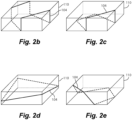
- Fig. 2b shows another frame continuous, i.e., closed, loop forming a frame composite rod 104 that crosses all six surfaces of the mandrel (and corresponding interior space 106, see Fig. 1 ), and crosses each of the top and bottom surfaces twice, as oriented in Fig. 2b.
- Fig. 2c shows another continuous, i.e. closed, loop frame composite rod 104 that crosses the three adjacent sides (top, front, and right sides), and the bottom surface of the mandrel 110, including crossing the bottom surface three times, as oriented in Fig. 2c.
- Fig. 2d shows another continuous or closed loop frame composite rod 104 that crosses the front, right, back, and left surfaces (the peripheral surfaces) of the mandrel 110, as oriented in Fig.
- Fig. 2e shows a similar frame composite rod 104 to that shown in Fig. 2c , but crossing the left surface of the mandrel instead of the right, as oriented in Fig. 2e .
- Figs. 2a-2e show representative examples which can be similarly extended to other mandrel shapes and/or frame rod designs.
- the lattice 102 of frame composite rods 104 includes a plurality of continuous loop frame composite rods 104, such as those described above with reference to Figs. 2a-2e , interconnected with the lattice 102.
- the lattice 102 also includes a plurality of dis-continuous or open loop frame composite rods 105 interconnected with the lattice 102.
- Figs. 4a and 4b show two-dimensional side views of two lattices 102, respectively, one with a less dense lattice design, and the other with a more dense lattice design. Number and geometries of frame composite rods 104 can be used to control the lattice density and structural integrity according to specifics of a given application.
- Figs. 5a-5d show frame composite rods 104 being formed on mandrels 110 shaped with a rectangular cross-section ( Fig. 5a ), with a rounded corner rectangular cross-section ( Fig. 5b ), with an oval, or more generally, convex cross-section ( Fig. 5c ), and with an arbitrary cross-section including both convex and concave segments ( Fig. 5d ).
- Fig. 5d In addition to different two-dimensional geometries of cross-sectional designs, different three-dimensional geometries of mandrels can be similarly applied.
- any suitable lattice structure can be used for an opto-mechanical support structure without departing from the scope of this disclosure.
- the frame composite rods 104, 105 are unidirectionally reinforced by fibers polymer-matrix composite elements, which can all be formed by an AFP arm 112, as shown in Fig. 2a .
- Fibers polymer-matrix composite elements which can all be formed by an AFP arm 112, as shown in Fig. 2a .
- Carbon, glass and organic (e.g., Kevlar) fibers or any of their combinations can be used, among others, for the reinforcement.
- Thermoplastics or thermosets can be used as the polymer matrix. As shown in Figs.
- intersections 114 in the lattice 102 of the frame composite rods 104 include interlaying of the composite layers 116 or groups of layers 116 of the respective intersecting frame composite rods 104, formed by laying the one layer (or group of layers) at a time in the intersection stack, every other layer (or group of layers) belonging to one of the intersecting respective frame composite rods 104.
- the frame composite rods 104 can be formed layer by layer (or one group of layers by another group of layers), one layer (or one group of layers 116) at a time to have any suitable cross-sectional profile.
- the frame composite rods 104 in Fig. 6b have rectangular, constant thickness cross-sections, shown in Fig. 7a .
- Any other suitable cross-sectional configuration can be used for the frame composite rods 104.
- Fig. 7b shows a frame composite rod 104 with a non-constant thickness where one surface of the cross-sectional profile is flat, i.e., the bottom layer 116 is flat, and the successive layers 116 upward from the bottom are successively narrower towards the top as oriented in Fig. 7b.
- Fig. 7c shows a non-constant thickness where opposed surfaces (i.e., the top and bottom layers 116 as oriented in Fig. 7c ) are both non-flat.
- Fig. 7b shows a frame composite rod 104 with a non-constant thickness where one surface of the cross-sectional profile is flat, i.e., the bottom layer 116 is flat, and the successive layers 116 upward from the bottom are successively narrower towards the top as oriented in Fig
- FIG. 7d shows a cross-sectional profile for a frame composite rod 104 with one rib 118 extending from a base, e.g., from the top or bottom layer
- Fig. 7e shows a cross-sectional profile with multiple ribs 118 extending from a base (with the base as the top layer in this example).
- Fig. 7f shows a cross-sectional frame composite rod profile with a hollow shape
- Fig. 7g shows one with a hollow shape having an insert 120 inside.
- the inserts 120 can be any suitable light-weight materials, for example, polymeric, foam, elastomeric, honeycomb, among others.
- the layers 116 can vary in material during the AFP process, giving a frame composite rod 104 with a cross-sectional profile having multiple different composite materials 122/124 in layers 116 varied through thickness of the cross-sectional profile, as shown in Fig. 7h .
- the multiple different materials 122/124 in layers 116 are varied through thickness and width of the cross-sectional profile, as shown in Fig. 7i .
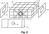
- one of the interstices 108 defines an optics or opto-mechanical aperture 126 therethrough for admittance of image data, e.g., optical or any portion of the electromagnetic spectrum for example, through the frame 100.
- the method includes removing the mandrel 110 (labeled in Fig. 1 ) from an interior space 106 of the frame 100 after forming the frame 100.
- the mandrel 110 can be removed by dissolving or washing the mandrel 120 away after forming the frame 100.
- Wall panels 128, e.g., of a composite monolithic or a sandwich design, can optionally be mounted to an exterior aspect of the frame 100 for protection of the interior space 106.
- Such wall panels 128 can include one or more aperture 130 therethrough, e.g., aligned with the optics aperture 126 of the lattice 102.
- the wall panels 128 can provide protection for optics/imaging components housed inside the lattice.
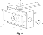
- FIG. 9 An example of usage of composite frames is illustrated in Fig. 9 .
- An optical and/or imaging assembly 132 e.g., including a camera, lens, telescope, or the like, is mounted inside the lattice 102 with an objective lens 134 aligned with the optical aperture 126 through one of the interstices 108 in the lattice 102 (labeled in Fig. 3 ).
- Two or more frames 100 constructed as disclosed herein can be connected together as a three-dimensional gimbal 10, where two axes of rotation A and B are indicated in Fig. 9 .
Landscapes
- Engineering & Computer Science (AREA)
- Mechanical Engineering (AREA)
- General Engineering & Computer Science (AREA)
- Robotics (AREA)
- Chemical & Material Sciences (AREA)
- Composite Materials (AREA)
- Physics & Mathematics (AREA)
- General Physics & Mathematics (AREA)
- Optics & Photonics (AREA)
Abstract
Description
- The present disclosure relates to opto-mechanical support structures, and more particularly to opto-mechanical support structures with frames of fiber-reinforced composite materials.
- Existing opto-mechanical support structures for optics and mechanical systems such as cameras and like imaging or information transmission systems are metallic based on shell designs with supportive ribs. Substitution of metal by fiber-reinforced polymer-matrix composites provides significant advantages such as lighter weight, corrosion resistance, durability, vibrational damping and more reliable supply chain availability without in advance ordering. Current composite structures usually mimic the existing metallic shell-based designs. However, current composite shell-based designs are limited by, among other things, relatively low stiffness and low strength properties in non-fiber orientations (transversal, shear, interlaminar) requiring their thickness increase with associated extra weight, complexity and cost of fabrication requiring considerable manual labor, additional risk of damage, especially in shell/ribs connections, and expensive quality/service control.
- The conventional techniques have been considered satisfactory for their intended purpose. However, there is an ever-present need for improved systems and methods for improved composite components for optics support structures with potential for both design and manufacturing improvement/optimization. This disclosure provides a solution for this need.
- A frame for an opto-mechanical support structure includes an interconnected lattice of frame composite rods defined about an interior space with interstices defined between the frame composite rods.
- The lattice of frame composite rods can include a plurality of continuous loop frame composite rods interconnected with the lattice. The lattice of frame composite rods can include a plurality of dis-continuous loop frame composite rods interconnected with the lattice. The frame composite rods can be unidirectionally fiber-reinforced composite elements, e.g. composite tapes or combination of such tapes. Intersections of the frame composite rods can include interlaying of the composite element layers of the respective intersecting frame composite rods.
- At least one of the frame composite rods can include a cross-sectional profile selected from the group consisting of: constant thickness, non-constant thickness where one surface of the cross-sectional profile is flat, non-constant thickness where opposed surfaces are both not flat, one rib extending from a base, multiple ribs extending from an external surface, a hollow shape, a hollow shape with an insert inside, multiple different materials in layers varied through thickness of the cross-sectional profile, and multiple different materials in layers varied through thickness and width of the cross-sectional profile.
- One of the interstices can define an opto-mechanical aperture therethrough for admittance of optics image data through the lattice and frame. Wall panels can be mounted to an exterior aspect of the lattice for protection of the interior space. At least one of the wall panels can include an aperture therethrough, aligned with the optical aperture of the lattice. An opto-mechanical assembly can be mounted inside the lattice and frame with an objective lens aligned with an optics aperture through one of the interstices in the lattice.
- At least one of the frame composite rods can form a continuous loop that extends across more than one surface of the interior space. The interior space can be six-sided and wherein at least one of the frame composite rods forms a continuous loop that extends across all six sides of the interior space. The interior space can be six-sided and wherein at least one of the frame composite rods forms a continuous loop that extends across three different sides of the interior space. The interior space can be six-sided and wherein at least one of the frame composite rods forms a continuous loop that extends across four different sides of the interior space. Two or more frames as described above can be connected together as a three-dimensional gimbal.
- A method of making an opto-mechanical frame includes forming a frame of interconnected lattice of frame composite rods using one or more fabrication processes by Automated Fiber Placement (AFP) technique around a mandrel. The method includes removing the mandrel from an interior space of the frame after forming the frame.
- The method can include removing the mandrel by dissolving or washing the mandrel away after forming the frame. Forming the frame can include using at least one AFP arm to articulate fibers around the mandrel relative to a fixed frame of reference. Forming the frame can include rotating the mandrel relative to the fixed frame of reference. Forming the frame can include forming interlayered intersections of the frame composite rods in the lattice on a one-layer-at-a-time basis.
- These and other features of the systems and methods of the subject disclosure will become more readily apparent to those skilled in the art from the following detailed description of the preferred embodiments taken in conjunction with the drawings.
- So that those skilled in the art to which the subject disclosure appertains will readily understand how to make and use the devices and methods of the subject disclosure without undue experimentation, preferred embodiments thereof will be described in detail herein below with reference to certain figures, wherein:
-
Fig. 1 is a schematic perspective view of an embodiment of a composite frame constructed in accordance with the present disclosure, showing the frame composite rods and interstices; -
Figs. 2a-2e are schematic perspective views of frame composite rods, showing representative continuous loop frame composite rods crossing different numbers of sides of the mandrel on an exemplary six-sided internal space; -
Fig. 3 is a schematic perspective view of a composite frame, showing the optical aperture in the frame; -
Figs. 4a-4b are schematic front two-dimensional views of composite frames, showing examples of two different densities of composite distribution; -
Figs. 5a-5d are schematic perspective views of mandrels for forming composite frames, showing representative examples of different mandrel shapes; -
Figs. 6a-6b are schematic in plane and cross-sectional views of an intersection of frame composite rods ofFig. 1 ; -
Figs. 7a-7i are schematic cross-sectional views of different examples of cross-sectional profiles for frame composite rods; -
Fig. 8 is an exploded perspective view of the composite frame ofFig. 1 , showing wall panels for protecting the interior space of the frame; and -
Fig. 9 is a schematic perspective view of a gimbal formed of two or more composite frames like the composite frame ofFig. 1 . - Reference will now be made to the drawings wherein like reference numerals identify similar structural features or aspects of the subject disclosure. For purposes of explanation and illustration, and not limitation, a partial view of an embodiment of a frame in accordance with the disclosure is shown in
Fig. 1 and is designated generally byreference character 100. Other embodiments of systems in accordance with the disclosure, or aspects thereof, are provided inFigs. 2-9 , as will be described. The systems and methods described herein can be used to form composite frames for optics or opto-mechanical systems. - The
frame 100 for an optical or other equipment support structure includes aninterconnected lattice 102 offrame composite rods 104 defined about aninterior space 106 withinterstices 108 defined between theframe composite rods 104. InFig. 1 , not all of theinterstices 108 are labeled for sake of clarity. Also shown inFig. 1 is themandrel 110 about which theframe composite rods 104 are formed.Fig. 1 shows the beginning of a frame structure, to which additionalframe composite rods 104 can be added to form acomplete frame 100, for example as shown inFig. 3 . -
Fig. 2a shows another beginning stage for forming aframe 100, with an Automated Fiber Placement (AFP)arm 112 forming a continuous, i.e., closed loopframe composite rod 104 about themandrel 110. The double arrows inFig. 2a schematically indicate examples of movement orientations of theAFP arm 112, e.g., relative to a stationary frame of reference, that can be used form forming theframe composite rods 104. In other embodiments, using advanced AFP capabilities, the AFParm 112 can move in all three space directions and similarly rotate in all three angular orientations. The circular arrows inFig. 2a schematically indicate examples of the movement or rotation of themandrel 110 itself, relative to the same stationary frame of reference, which can also be used for forming the framecomposite rods 104. Depending on the specifics of AFP implementation, themandrel 110 can move and/or rotate in different directions and orientations. In this example, the framecomposite rod 104 inFig. 2a forms a continuous, i.e., closed, loop on itself and crosses over four faces of the 6-sided mandrel (and correspondinginterior space 106, seeFig. 1 ), e.g., the top, front, bottom, and back surfaces as oriented inFig. 2a . -
Fig. 2b shows another frame continuous, i.e., closed, loop forming a framecomposite rod 104 that crosses all six surfaces of the mandrel (and correspondinginterior space 106, seeFig. 1 ), and crosses each of the top and bottom surfaces twice, as oriented inFig. 2b. Fig. 2c shows another continuous, i.e. closed, loop framecomposite rod 104 that crosses the three adjacent sides (top, front, and right sides), and the bottom surface of themandrel 110, including crossing the bottom surface three times, as oriented inFig. 2c. Fig. 2d shows another continuous or closed loop framecomposite rod 104 that crosses the front, right, back, and left surfaces (the peripheral surfaces) of themandrel 110, as oriented inFig. 2d. Fig. 2e shows a similar framecomposite rod 104 to that shown inFig. 2c , but crossing the left surface of the mandrel instead of the right, as oriented inFig. 2e . Those skilled in the art will readily appreciate that any suitable continuous, i.e., closed, loop pattern can be used for framecomposite rods 104 without departing from the scope of this disclosure, i.e.,Figs. 2a-2e show representative examples which can be similarly extended to other mandrel shapes and/or frame rod designs. - With reference now to an example of a composite frame shown in
Fig. 3 , thelattice 102 of framecomposite rods 104 includes a plurality of continuous loop framecomposite rods 104, such as those described above with reference toFigs. 2a-2e , interconnected with thelattice 102. Thelattice 102 also includes a plurality of dis-continuous or open loop framecomposite rods 105 interconnected with thelattice 102.Figs. 4a and 4b show two-dimensional side views of twolattices 102, respectively, one with a less dense lattice design, and the other with a more dense lattice design. Number and geometries of framecomposite rods 104 can be used to control the lattice density and structural integrity according to specifics of a given application. - Additionally, the
lattice 102 needs not to conform to arectangular mandrel 110 orinterior space 106 with rectangular cross-sections (labeled inFig. 1 ).Figs. 5a-5d show framecomposite rods 104 being formed onmandrels 110 shaped with a rectangular cross-section (Fig. 5a ), with a rounded corner rectangular cross-section (Fig. 5b ), with an oval, or more generally, convex cross-section (Fig. 5c ), and with an arbitrary cross-section including both convex and concave segments (Fig. 5d ). In addition to different two-dimensional geometries of cross-sectional designs, different three-dimensional geometries of mandrels can be similarly applied. Those skilled in the art will readily appreciate that any suitable lattice structure can be used for an opto-mechanical support structure without departing from the scope of this disclosure. - The frame
composite rods AFP arm 112, as shown inFig. 2a . Carbon, glass and organic (e.g., Kevlar) fibers or any of their combinations can be used, among others, for the reinforcement. Thermoplastics or thermosets can be used as the polymer matrix. As shown inFigs. 6a-6b ,intersections 114 in thelattice 102 of the framecomposite rods 104 include interlaying of thecomposite layers 116 or groups oflayers 116 of the respective intersecting framecomposite rods 104, formed by laying the one layer (or group of layers) at a time in the intersection stack, every other layer (or group of layers) belonging to one of the intersecting respective framecomposite rods 104. The framecomposite rods 104 can be formed layer by layer (or one group of layers by another group of layers), one layer (or one group of layers 116) at a time to have any suitable cross-sectional profile. - The frame
composite rods 104 inFig. 6b have rectangular, constant thickness cross-sections, shown inFig. 7a . Any other suitable cross-sectional configuration can be used for the framecomposite rods 104.Fig. 7b shows a framecomposite rod 104 with a non-constant thickness where one surface of the cross-sectional profile is flat, i.e., thebottom layer 116 is flat, and thesuccessive layers 116 upward from the bottom are successively narrower towards the top as oriented inFig. 7b. Fig. 7c shows a non-constant thickness where opposed surfaces (i.e., the top andbottom layers 116 as oriented inFig. 7c ) are both non-flat.Fig. 7d shows a cross-sectional profile for a framecomposite rod 104 with onerib 118 extending from a base, e.g., from the top or bottom layer, andFig. 7e shows a cross-sectional profile withmultiple ribs 118 extending from a base (with the base as the top layer in this example).Fig. 7f shows a cross-sectional frame composite rod profile with a hollow shape, andFig. 7g shows one with a hollow shape having aninsert 120 inside. Theinserts 120 can be any suitable light-weight materials, for example, polymeric, foam, elastomeric, honeycomb, among others. Thelayers 116 can vary in material during the AFP process, giving a framecomposite rod 104 with a cross-sectional profile having multiple differentcomposite materials 122/124 inlayers 116 varied through thickness of the cross-sectional profile, as shown inFig. 7h . InFig. 7i , the multipledifferent materials 122/124 inlayers 116 are varied through thickness and width of the cross-sectional profile, as shown inFig. 7i . - With reference now to
Fig. 8 , one of theinterstices 108 defines an optics or opto-mechanical aperture 126 therethrough for admittance of image data, e.g., optical or any portion of the electromagnetic spectrum for example, through theframe 100. After forming thelattice 102, the method includes removing the mandrel 110 (labeled inFig. 1 ) from aninterior space 106 of theframe 100 after forming theframe 100. Themandrel 110 can be removed by dissolving or washing themandrel 120 away after forming theframe 100.Wall panels 128, e.g., of a composite monolithic or a sandwich design, can optionally be mounted to an exterior aspect of theframe 100 for protection of theinterior space 106.Such wall panels 128 can include one ormore aperture 130 therethrough, e.g., aligned with the optics aperture 126 of thelattice 102. Thewall panels 128 can provide protection for optics/imaging components housed inside the lattice. - An example of usage of composite frames is illustrated in
Fig. 9 . An optical and/orimaging assembly 132, e.g., including a camera, lens, telescope, or the like, is mounted inside thelattice 102 with anobjective lens 134 aligned with the optical aperture 126 through one of theinterstices 108 in the lattice 102 (labeled inFig. 3 ). Two ormore frames 100 constructed as disclosed herein can be connected together as a three-dimensional gimbal 10, where two axes of rotation A and B are indicated inFig. 9 . - The methods and systems of the present disclosure, as described above and shown in the drawings, provide for forming composite frames for optics systems. While the apparatus and methods of the subject disclosure have been shown and described with reference to preferred embodiments, those skilled in the art will readily appreciate that changes and/or modifications may be made thereto without departing from the scope of the subject disclosure.
Claims (15)
- A frame (100) for an opto-mechanical support structure comprising:
an interconnected lattice (102) of fiber-reinforced frame composite rods (104) defined about an interior space (106) with interstices (108) defined between the frame composite rods. - The frame as recited in claim 1, wherein the lattice (102) of frame composite rods includes a plurality of continuous loop frame composite rods (104) interconnected with the lattice; and/or
wherein the lattice (102) of frame composite rods includes a plurality of dis-continuous loop frame composite rods (104) interconnected with the lattice. - The frame as recited in claim 1 or 2, wherein the frame composite rods (104) are unidirectionally fiber reinforced polymer-matrix composite elements; and preferably wherein intersections (114) of the frame composite rods (104) include interlaying of the composite individual layers (116) or groups of layers of the respective intersecting frame composite rods.
- The frame as recited in any preceding claim, wherein at least one of the frame composite rods (104) includes a cross-sectional profile selected from the group consisting of: constant thickness, non-constant thickness where one surface of the cross-sectional profile is flat, non-constant thickness where opposed surfaces are both non-flat, one rib (118) extending from an external surface or base, multiple ribs (118) extending from a base or external surface, a hollow shape, a hollow shape with an insert (120) inside, multiple different materials in layers varied through thickness of the cross-sectional profile, and multiple different materials (112, 124) in layers varied through thickness and width of the cross-sectional profile.
- The frame as recited in any preceding claim, wherein one of the interstices (108) defines an aperture (126) for equipment used for transmission or receiving information.
- The frame as recited in any preceding claim, further comprising wall panels (128) mounted to an exterior aspect of the lattice (102) for protection of the interior space (106); and preferably
wherein at least one of the wall panels (128) includes an aperture (130) therethrough, aligned with the aperture (126) of the lattice (102). - The frame as recited in any preceding claim, further comprising an optical-mechanical assembly (132) mounted inside the lattice (102) with an objective lens (134) aligned with an aperture (126) through one of the interstices (108) in the lattice (102).
- The frame as recited in any preceding claim, wherein at least one of the frame composite rods (104) forms a continuous loop that extends across more than one surface of the interior space (106).
- The frame as recited in claim 8, wherein the interior space (106) is six-sided and wherein at least one of the frame composite rods (104) forms a continuous loop that extends across all six sides of the interior space; or whereinthe interior space is six-sided and wherein at least one of the frame composite rods forms a continuous loop that extends across three different sides of the interior space; or whereinthe interior space is six-sided and wherein at least one of the frame composite rods forms a continuous loop that extends across four different sides of the interior space.
- An assembly of two or more frames as recited in any preceding claim, wherein the two or more frames (100) are connected together as a three-dimensional gimbal.
- A method of making an opto-mechanical frame comprising:forming a frame of interconnected lattice of frame composite rods using one or more fabricated by Automated Fiber Placement (AFP) around a mandrel; andremoving the mandrel from an interior space of the frame after forming the frame.
- The method as recited in claim 11, wherein removing the mandrel includes dissolving or washing the mandrel away after forming the frame.
- The method as recited in claim 11 or 12, wherein forming the frame includes using at least one moving AFP arm to articulate fibers around the mandrel relative to a fixed frame of reference.
- The method as recited in claim 13, wherein forming the frame includes rotating the mandrel relative to the fixed frame of reference.
- The method as recited in any of claims 11 to 14, wherein forming the frame includes forming interlayered intersections of the frame composite rods in the lattice on a one-layer-at-a-time basis.
Applications Claiming Priority (1)
| Application Number | Priority Date | Filing Date | Title |
|---|---|---|---|
| US17/679,489 US12181098B2 (en) | 2022-02-24 | 2022-02-24 | Composite frames for opto-mechanical support structures |
Publications (2)
| Publication Number | Publication Date |
|---|---|
| EP4234215A1 true EP4234215A1 (en) | 2023-08-30 |
| EP4234215B1 EP4234215B1 (en) | 2025-09-03 |
Family
ID=85283719
Family Applications (1)
| Application Number | Title | Priority Date | Filing Date |
|---|---|---|---|
| EP23157403.9A Active EP4234215B1 (en) | 2022-02-24 | 2023-02-17 | Composite frame for opto-mechanical support structures and corresponding manufacturing method |
Country Status (2)
| Country | Link |
|---|---|
| US (1) | US12181098B2 (en) |
| EP (1) | EP4234215B1 (en) |
Citations (3)
| Publication number | Priority date | Publication date | Assignee | Title |
|---|---|---|---|---|
| US20070145633A1 (en) * | 2003-12-12 | 2007-06-28 | Shonan Design Co., Ltd. | Method for manufacturing hollow model |
| US20130337207A1 (en) * | 2012-06-14 | 2013-12-19 | Airbus Operations Gmbh | Method and a device for the manufacturing of a lightweight structure, and also a lightweight structure |
| US20210206135A1 (en) * | 2020-01-02 | 2021-07-08 | The Boeing Company | Composite structural panels and methods of forming thereof |
Family Cites Families (12)
| Publication number | Priority date | Publication date | Assignee | Title |
|---|---|---|---|---|
| US4690960A (en) * | 1981-01-14 | 1987-09-01 | Nippon Electric Co., Ltd. | Vibration damping material |
| US4899323A (en) * | 1986-08-04 | 1990-02-06 | Bridgestone Corporation | Anti-seismic device |
| RU2116934C1 (en) * | 1997-05-06 | 1998-08-10 | Акционерное общество "Центр перспективных разработок акционерного общества "Центральный научно-исследовательский институт специального машиностроения" | Rib made from composite materials (versions) and device for manufacture of its flat fin-cellular structure |
| US7204951B2 (en) * | 2002-07-30 | 2007-04-17 | Rocky Mountain Composites, Inc. | Method of assembling a single piece co-cured structure |
| US8136782B2 (en) * | 2008-06-09 | 2012-03-20 | Rowland Jay F | Systems and methods for elevating an equipment unit |
| US10654246B2 (en) | 2012-04-28 | 2020-05-19 | General Electric Company | Composite article and methods therefor |
| US9395604B1 (en) * | 2015-06-05 | 2016-07-19 | Rosemount Aerospace Inc. | Camera adjustment tool and method |
| US20170087745A1 (en) | 2015-09-30 | 2017-03-30 | The Boeing Company | Fiber-reinforced Thermoplastic Composite Structure and Method for Making the Same |
| WO2020032663A1 (en) | 2018-08-09 | 2020-02-13 | 엘지전자 주식회사 | Method by which node configures slot format in wireless communication system, and node using method |
| ES2944508T3 (en) | 2018-12-21 | 2023-06-21 | Cytec Ind Inc | Automated placement of prepreg tapes to form composite components |
| US20200326178A1 (en) * | 2019-04-14 | 2020-10-15 | PCS Solutions, LLC. | Apparatus for holding a laser distance tool for determining the elevation of features of an underground structure |
| US11933350B2 (en) * | 2022-05-16 | 2024-03-19 | Goodrich Corporation | Joints of composite frames for optics support structure |
-
2022
- 2022-02-24 US US17/679,489 patent/US12181098B2/en active Active
-
2023
- 2023-02-17 EP EP23157403.9A patent/EP4234215B1/en active Active
Patent Citations (3)
| Publication number | Priority date | Publication date | Assignee | Title |
|---|---|---|---|---|
| US20070145633A1 (en) * | 2003-12-12 | 2007-06-28 | Shonan Design Co., Ltd. | Method for manufacturing hollow model |
| US20130337207A1 (en) * | 2012-06-14 | 2013-12-19 | Airbus Operations Gmbh | Method and a device for the manufacturing of a lightweight structure, and also a lightweight structure |
| US20210206135A1 (en) * | 2020-01-02 | 2021-07-08 | The Boeing Company | Composite structural panels and methods of forming thereof |
Also Published As
| Publication number | Publication date |
|---|---|
| US12181098B2 (en) | 2024-12-31 |
| US20230265964A1 (en) | 2023-08-24 |
| EP4234215B1 (en) | 2025-09-03 |
Similar Documents
| Publication | Publication Date | Title |
|---|---|---|
| US8418730B2 (en) | Three-dimensional cellular light structures weaving by helical wires and the manufacturing method of the same | |
| US8642168B2 (en) | Composite structure having reinforced core and method of making the same | |
| EP3022801B1 (en) | Advanced composite radome and method of manufacturing | |
| CA2763113C (en) | Structural component and production method for a structural component | |
| US4715560A (en) | Composite cruciform structure for joining intersecting structural members of an airframe and the like | |
| CN102741045B (en) | Composite core material and preparation method thereof | |
| US20190344908A1 (en) | Method For Forming A Structural Component For An Airframe Of An Aircraft Or Spacecraft And Structural Component For An Airframe Of An Aircraft Or Spacecraft | |
| EP0970800A2 (en) | Continuous intersecting braided composite structure and method of making same | |
| EP3345754B1 (en) | Sandwich panel with recessed channel network | |
| EP4234215B1 (en) | Composite frame for opto-mechanical support structures and corresponding manufacturing method | |
| US7429114B2 (en) | Light-weight mirror blank assembly | |
| De Nicola et al. | An efficient and scalable manufacturing method for CFRP lattice structures for satellite central tube and large deployable antenna boom applications | |
| RU2684999C1 (en) | Method of manufacturing a propeller blade filling body and a propeller blade filling body comprising at least one cellular system with closed cells | |
| GB2074117A (en) | Composite structure for joining intersecting structural members of an airframe | |
| US8663812B2 (en) | Method for preparing a cellular material based on hollow metal beads | |
| EP4279754B1 (en) | Joints of composite frames for optics support structure | |
| EP0034453A1 (en) | Process and apparatus for the manufacture of cellular composites | |
| CN115675825B (en) | A method for preparing a flexible and high-strength matrix honeycomb | |
| US20200216988A1 (en) | Additive manufacturing-3d printing of three-dimensional woven structures | |
| JP2000013117A (en) | Light weight three-dimensional waveguide | |
| Khatua et al. | Selectively embedding multiple spatially steered fibers in polymer composite parts made using vat photopolymerization | |
| JP4599002B2 (en) | Expanded structure | |
| Khatua et al. | Robot-aided selective embedding of a spatially steered fiber in polymer composite parts made using vat photopolymerization | |
| CN116413892B (en) | Carbon fiber frame prefabricated body of space remote sensor and preparation method thereof | |
| Christie et al. | Filigree Shell Slabs |
Legal Events
| Date | Code | Title | Description |
|---|---|---|---|
| PUAI | Public reference made under article 153(3) epc to a published international application that has entered the european phase |
Free format text: ORIGINAL CODE: 0009012 |
|
| STAA | Information on the status of an ep patent application or granted ep patent |
Free format text: STATUS: THE APPLICATION HAS BEEN PUBLISHED |
|
| AK | Designated contracting states |
Kind code of ref document: A1 Designated state(s): AL AT BE BG CH CY CZ DE DK EE ES FI FR GB GR HR HU IE IS IT LI LT LU LV MC ME MK MT NL NO PL PT RO RS SE SI SK SM TR |
|
| STAA | Information on the status of an ep patent application or granted ep patent |
Free format text: STATUS: REQUEST FOR EXAMINATION WAS MADE |
|
| 17P | Request for examination filed |
Effective date: 20240226 |
|
| RBV | Designated contracting states (corrected) |
Designated state(s): AL AT BE BG CH CY CZ DE DK EE ES FI FR GB GR HR HU IE IS IT LI LT LU LV MC ME MK MT NL NO PL PT RO RS SE SI SK SM TR |
|
| GRAP | Despatch of communication of intention to grant a patent |
Free format text: ORIGINAL CODE: EPIDOSNIGR1 |
|
| STAA | Information on the status of an ep patent application or granted ep patent |
Free format text: STATUS: GRANT OF PATENT IS INTENDED |
|
| RIC1 | Information provided on ipc code assigned before grant |
Ipc: G02B 7/02 20210101ALI20250320BHEP Ipc: B29C 33/52 20060101ALI20250320BHEP Ipc: B29C 70/38 20060101AFI20250320BHEP |
|
| INTG | Intention to grant announced |
Effective date: 20250401 |
|
| GRAS | Grant fee paid |
Free format text: ORIGINAL CODE: EPIDOSNIGR3 |
|
| GRAA | (expected) grant |
Free format text: ORIGINAL CODE: 0009210 |
|
| STAA | Information on the status of an ep patent application or granted ep patent |
Free format text: STATUS: THE PATENT HAS BEEN GRANTED |
|
| AK | Designated contracting states |
Kind code of ref document: B1 Designated state(s): AL AT BE BG CH CY CZ DE DK EE ES FI FR GB GR HR HU IE IS IT LI LT LU LV MC ME MK MT NL NO PL PT RO RS SE SI SK SM TR |
|
| REG | Reference to a national code |
Ref country code: CH Ref legal event code: EP |
|
| REG | Reference to a national code |
Ref country code: DE Ref legal event code: R096 Ref document number: 602023006210 Country of ref document: DE |
|
| REG | Reference to a national code |
Ref country code: IE Ref legal event code: FG4D |
|
| REG | Reference to a national code |
Ref country code: NL Ref legal event code: MP Effective date: 20250903 |
|
| PG25 | Lapsed in a contracting state [announced via postgrant information from national office to epo] |
Ref country code: NO Free format text: LAPSE BECAUSE OF FAILURE TO SUBMIT A TRANSLATION OF THE DESCRIPTION OR TO PAY THE FEE WITHIN THE PRESCRIBED TIME-LIMIT Effective date: 20251203 |
|
| REG | Reference to a national code |
Ref country code: LT Ref legal event code: MG9D |
|
| PG25 | Lapsed in a contracting state [announced via postgrant information from national office to epo] |
Ref country code: FI Free format text: LAPSE BECAUSE OF FAILURE TO SUBMIT A TRANSLATION OF THE DESCRIPTION OR TO PAY THE FEE WITHIN THE PRESCRIBED TIME-LIMIT Effective date: 20250903 |
|
| PG25 | Lapsed in a contracting state [announced via postgrant information from national office to epo] |
Ref country code: HR Free format text: LAPSE BECAUSE OF FAILURE TO SUBMIT A TRANSLATION OF THE DESCRIPTION OR TO PAY THE FEE WITHIN THE PRESCRIBED TIME-LIMIT Effective date: 20250903 |
|
| PG25 | Lapsed in a contracting state [announced via postgrant information from national office to epo] |
Ref country code: GR Free format text: LAPSE BECAUSE OF FAILURE TO SUBMIT A TRANSLATION OF THE DESCRIPTION OR TO PAY THE FEE WITHIN THE PRESCRIBED TIME-LIMIT Effective date: 20251204 |
|
| PG25 | Lapsed in a contracting state [announced via postgrant information from national office to epo] |
Ref country code: SE Free format text: LAPSE BECAUSE OF FAILURE TO SUBMIT A TRANSLATION OF THE DESCRIPTION OR TO PAY THE FEE WITHIN THE PRESCRIBED TIME-LIMIT Effective date: 20250903 |
|
| PG25 | Lapsed in a contracting state [announced via postgrant information from national office to epo] |
Ref country code: LV Free format text: LAPSE BECAUSE OF FAILURE TO SUBMIT A TRANSLATION OF THE DESCRIPTION OR TO PAY THE FEE WITHIN THE PRESCRIBED TIME-LIMIT Effective date: 20250903 |
|
| PG25 | Lapsed in a contracting state [announced via postgrant information from national office to epo] |
Ref country code: BG Free format text: LAPSE BECAUSE OF FAILURE TO SUBMIT A TRANSLATION OF THE DESCRIPTION OR TO PAY THE FEE WITHIN THE PRESCRIBED TIME-LIMIT Effective date: 20250903 Ref country code: PL Free format text: LAPSE BECAUSE OF FAILURE TO SUBMIT A TRANSLATION OF THE DESCRIPTION OR TO PAY THE FEE WITHIN THE PRESCRIBED TIME-LIMIT Effective date: 20250903 |
|
| PG25 | Lapsed in a contracting state [announced via postgrant information from national office to epo] |
Ref country code: RS Free format text: LAPSE BECAUSE OF FAILURE TO SUBMIT A TRANSLATION OF THE DESCRIPTION OR TO PAY THE FEE WITHIN THE PRESCRIBED TIME-LIMIT Effective date: 20251203 |
|
| PG25 | Lapsed in a contracting state [announced via postgrant information from national office to epo] |
Ref country code: ES Free format text: LAPSE BECAUSE OF FAILURE TO SUBMIT A TRANSLATION OF THE DESCRIPTION OR TO PAY THE FEE WITHIN THE PRESCRIBED TIME-LIMIT Effective date: 20250903 |
|
| REG | Reference to a national code |
Ref country code: AT Ref legal event code: MK05 Ref document number: 1832537 Country of ref document: AT Kind code of ref document: T Effective date: 20250903 |
|
| PG25 | Lapsed in a contracting state [announced via postgrant information from national office to epo] |
Ref country code: NL Free format text: LAPSE BECAUSE OF FAILURE TO SUBMIT A TRANSLATION OF THE DESCRIPTION OR TO PAY THE FEE WITHIN THE PRESCRIBED TIME-LIMIT Effective date: 20250903 |
|
| PG25 | Lapsed in a contracting state [announced via postgrant information from national office to epo] |
Ref country code: SM Free format text: LAPSE BECAUSE OF FAILURE TO SUBMIT A TRANSLATION OF THE DESCRIPTION OR TO PAY THE FEE WITHIN THE PRESCRIBED TIME-LIMIT Effective date: 20250903 |
|
| PGFP | Annual fee paid to national office [announced via postgrant information from national office to epo] |
Ref country code: DE Payment date: 20260121 Year of fee payment: 4 |
|
| PG25 | Lapsed in a contracting state [announced via postgrant information from national office to epo] |
Ref country code: AT Free format text: LAPSE BECAUSE OF FAILURE TO SUBMIT A TRANSLATION OF THE DESCRIPTION OR TO PAY THE FEE WITHIN THE PRESCRIBED TIME-LIMIT Effective date: 20250903 |
|
| PG25 | Lapsed in a contracting state [announced via postgrant information from national office to epo] |
Ref country code: IT Free format text: LAPSE BECAUSE OF FAILURE TO SUBMIT A TRANSLATION OF THE DESCRIPTION OR TO PAY THE FEE WITHIN THE PRESCRIBED TIME-LIMIT Effective date: 20250903 |
|
| PG25 | Lapsed in a contracting state [announced via postgrant information from national office to epo] |
Ref country code: IS Free format text: LAPSE BECAUSE OF FAILURE TO SUBMIT A TRANSLATION OF THE DESCRIPTION OR TO PAY THE FEE WITHIN THE PRESCRIBED TIME-LIMIT Effective date: 20260103 |
|
| PGFP | Annual fee paid to national office [announced via postgrant information from national office to epo] |
Ref country code: FR Payment date: 20260121 Year of fee payment: 4 |
|
| PG25 | Lapsed in a contracting state [announced via postgrant information from national office to epo] |
Ref country code: CZ Free format text: LAPSE BECAUSE OF FAILURE TO SUBMIT A TRANSLATION OF THE DESCRIPTION OR TO PAY THE FEE WITHIN THE PRESCRIBED TIME-LIMIT Effective date: 20250903 Ref country code: PT Free format text: LAPSE BECAUSE OF FAILURE TO SUBMIT A TRANSLATION OF THE DESCRIPTION OR TO PAY THE FEE WITHIN THE PRESCRIBED TIME-LIMIT Effective date: 20260105 |
|
| PG25 | Lapsed in a contracting state [announced via postgrant information from national office to epo] |
Ref country code: SK Free format text: LAPSE BECAUSE OF FAILURE TO SUBMIT A TRANSLATION OF THE DESCRIPTION OR TO PAY THE FEE WITHIN THE PRESCRIBED TIME-LIMIT Effective date: 20250903 Ref country code: EE Free format text: LAPSE BECAUSE OF FAILURE TO SUBMIT A TRANSLATION OF THE DESCRIPTION OR TO PAY THE FEE WITHIN THE PRESCRIBED TIME-LIMIT Effective date: 20250903 |