EP4234167A2 - Multi-function skateboard tool - Google Patents
Multi-function skateboard tool Download PDFInfo
- Publication number
- EP4234167A2 EP4234167A2 EP23157668.7A EP23157668A EP4234167A2 EP 4234167 A2 EP4234167 A2 EP 4234167A2 EP 23157668 A EP23157668 A EP 23157668A EP 4234167 A2 EP4234167 A2 EP 4234167A2
- Authority
- EP
- European Patent Office
- Prior art keywords
- case
- tool
- bar extension
- wrench
- retaining feature
- Prior art date
- Legal status (The legal status is an assumption and is not a legal conclusion. Google has not performed a legal analysis and makes no representation as to the accuracy of the status listed.)
- Pending
Links
Images


Classifications
-
- B—PERFORMING OPERATIONS; TRANSPORTING
- B25—HAND TOOLS; PORTABLE POWER-DRIVEN TOOLS; MANIPULATORS
- B25G—HANDLES FOR HAND IMPLEMENTS
- B25G1/00—Handle constructions
- B25G1/08—Handle constructions with provision for storing tool elements
- B25G1/085—Handle constructions with provision for storing tool elements for screwdrivers, wrenches or spanners
-
- B—PERFORMING OPERATIONS; TRANSPORTING
- B25—HAND TOOLS; PORTABLE POWER-DRIVEN TOOLS; MANIPULATORS
- B25B—TOOLS OR BENCH DEVICES NOT OTHERWISE PROVIDED FOR, FOR FASTENING, CONNECTING, DISENGAGING OR HOLDING
- B25B13/00—Spanners; Wrenches
- B25B13/46—Spanners; Wrenches of the ratchet type, for providing a free return stroke of the handle
-
- B—PERFORMING OPERATIONS; TRANSPORTING
- B25—HAND TOOLS; PORTABLE POWER-DRIVEN TOOLS; MANIPULATORS
- B25B—TOOLS OR BENCH DEVICES NOT OTHERWISE PROVIDED FOR, FOR FASTENING, CONNECTING, DISENGAGING OR HOLDING
- B25B13/00—Spanners; Wrenches
- B25B13/02—Spanners; Wrenches with rigid jaws
- B25B13/06—Spanners; Wrenches with rigid jaws of socket type
-
- B—PERFORMING OPERATIONS; TRANSPORTING
- B25—HAND TOOLS; PORTABLE POWER-DRIVEN TOOLS; MANIPULATORS
- B25B—TOOLS OR BENCH DEVICES NOT OTHERWISE PROVIDED FOR, FOR FASTENING, CONNECTING, DISENGAGING OR HOLDING
- B25B13/00—Spanners; Wrenches
- B25B13/46—Spanners; Wrenches of the ratchet type, for providing a free return stroke of the handle
- B25B13/461—Spanners; Wrenches of the ratchet type, for providing a free return stroke of the handle with concentric driving and driven member
- B25B13/462—Spanners; Wrenches of the ratchet type, for providing a free return stroke of the handle with concentric driving and driven member the ratchet parts engaging in a direction radial to the tool operating axis
- B25B13/465—Spanners; Wrenches of the ratchet type, for providing a free return stroke of the handle with concentric driving and driven member the ratchet parts engaging in a direction radial to the tool operating axis a pawl engaging an internally toothed ring
-
- B—PERFORMING OPERATIONS; TRANSPORTING
- B25—HAND TOOLS; PORTABLE POWER-DRIVEN TOOLS; MANIPULATORS
- B25B—TOOLS OR BENCH DEVICES NOT OTHERWISE PROVIDED FOR, FOR FASTENING, CONNECTING, DISENGAGING OR HOLDING
- B25B5/00—Clamps
- B25B5/06—Arrangements for positively actuating jaws
- B25B5/067—C-clamps
-
- B—PERFORMING OPERATIONS; TRANSPORTING
- B25—HAND TOOLS; PORTABLE POWER-DRIVEN TOOLS; MANIPULATORS
- B25F—COMBINATION OR MULTI-PURPOSE TOOLS NOT OTHERWISE PROVIDED FOR; DETAILS OR COMPONENTS OF PORTABLE POWER-DRIVEN TOOLS NOT PARTICULARLY RELATED TO THE OPERATIONS PERFORMED AND NOT OTHERWISE PROVIDED FOR
- B25F1/00—Combination or multi-purpose hand tools
- B25F1/02—Combination or multi-purpose hand tools with interchangeable or adjustable tool elements
- B25F1/04—Combination or multi-purpose hand tools with interchangeable or adjustable tool elements wherein the elements are brought into working positions by a pivoting or sliding movement
-
- B—PERFORMING OPERATIONS; TRANSPORTING
- B25—HAND TOOLS; PORTABLE POWER-DRIVEN TOOLS; MANIPULATORS
- B25H—WORKSHOP EQUIPMENT, e.g. FOR MARKING-OUT WORK; STORAGE MEANS FOR WORKSHOPS
- B25H3/00—Storage means or arrangements for workshops facilitating access to, or handling of, work tools or instruments
- B25H3/003—Holders for drill bits or the like
-
- B—PERFORMING OPERATIONS; TRANSPORTING
- B23—MACHINE TOOLS; METAL-WORKING NOT OTHERWISE PROVIDED FOR
- B23G—THREAD CUTTING; WORKING OF SCREWS, BOLT HEADS, OR NUTS, IN CONJUNCTION THEREWITH
- B23G2200/00—Details of threading tools
- B23G2200/14—Multifunctional threading tools
- B23G2200/143—Tools comprising means for drilling
-
- B—PERFORMING OPERATIONS; TRANSPORTING
- B23—MACHINE TOOLS; METAL-WORKING NOT OTHERWISE PROVIDED FOR
- B23G—THREAD CUTTING; WORKING OF SCREWS, BOLT HEADS, OR NUTS, IN CONJUNCTION THEREWITH
- B23G5/00—Thread-cutting tools; Die-heads
- B23G5/02—Thread-cutting tools; Die-heads without means for adjustment
- B23G5/04—Dies
-
- B—PERFORMING OPERATIONS; TRANSPORTING
- B23—MACHINE TOOLS; METAL-WORKING NOT OTHERWISE PROVIDED FOR
- B23G—THREAD CUTTING; WORKING OF SCREWS, BOLT HEADS, OR NUTS, IN CONJUNCTION THEREWITH
- B23G5/00—Thread-cutting tools; Die-heads
- B23G5/20—Thread-cutting tools; Die-heads combined with other tools, e.g. drills
-
- B—PERFORMING OPERATIONS; TRANSPORTING
- B25—HAND TOOLS; PORTABLE POWER-DRIVEN TOOLS; MANIPULATORS
- B25B—TOOLS OR BENCH DEVICES NOT OTHERWISE PROVIDED FOR, FOR FASTENING, CONNECTING, DISENGAGING OR HOLDING
- B25B13/00—Spanners; Wrenches
- B25B13/48—Spanners; Wrenches for special purposes
-
- B—PERFORMING OPERATIONS; TRANSPORTING
- B25—HAND TOOLS; PORTABLE POWER-DRIVEN TOOLS; MANIPULATORS
- B25B—TOOLS OR BENCH DEVICES NOT OTHERWISE PROVIDED FOR, FOR FASTENING, CONNECTING, DISENGAGING OR HOLDING
- B25B23/00—Details of, or accessories for, spanners, wrenches, screwdrivers
- B25B23/16—Handles
-
- B—PERFORMING OPERATIONS; TRANSPORTING
- B25—HAND TOOLS; PORTABLE POWER-DRIVEN TOOLS; MANIPULATORS
- B25G—HANDLES FOR HAND IMPLEMENTS
- B25G3/00—Attaching handles to the implements
Definitions
- Embodiments of the subject matter described herein relate generally to multi-function tools and accessories of the type used for skateboards.
- Skateboarding is a wonderful sport that has become more popular with America's youth than little league baseball, Pop Warner football, and other traditional sporting activities.
- a skateboard includes the following fundamental components: a deck; four wheels; and two trucks that attach the wheels to the deck and which serve as turning mechanisms for the skateboard.
- Each truck is attached to the deck using nuts and bolts, and each wheel is attached to the threaded end of a truck axle using a nut.
- the turning responsiveness of each truck is adjustable by tightening or loosening a kingpin nut. Accordingly, assembly, maintenance, and adjustment of a skateboard requires a variety of tools (e.g., screwdrivers, wrenches, sockets, or the like).
- skateboard tools are "all-in-one" designs that include features that are specifically sized and configured for standard sized truck mounting hardware, axle nuts, and kingpin nuts.
- conventional skateboard tool designs may be convenient and/or compact, those benefits can be outweighed by various shortcomings and deficiencies. For example, some low-cost skateboard tools break easy or have parts that wear out too soon. As another example, traditional skateboard tools may be cumbersome and difficult to use, which can be bothersome when quick adjustment or assembly is required.
- An embodiment of the tool includes: a case having a top side, a bottom side, a front side, a back side, a right side, and a left side; a drive ratchet installed in a ratchet cavity formed in the case, the drive ratchet comprising a fitting exposed at the top side of the case and further comprising a toggle switch exposed at the bottom side of the case, wherein manipulation of the toggle switch changes direction of the drive ratchet, and wherein the fitting is configured to receive sockets and a bar extension for the sockets; a threading die held within a die cavity formed in the case, the threading die comprising cutting threads to form or repair external threads; a file attached to the case such that at least a portion of a working surface of the file is exposed; a wrench retaining feature integrally formed in the case, the wrench retaining feature configured to secure a wrench to the case in a removable manner; a plurality of socket retaining features integrally formed in the case, each of the
- the file is attached at or near an edge of the case.
- the tool further comprises a wrench tool removably coupled to the case via the wrench retaining feature, a plurality of different sized socket tools removably coupled to the case via the plurality of socket retaining features, and a bar extension tool removably coupled to the case via the bar extension retaining feature, wherein the drive ratchet and the fitting are compatible with the socket tools and the bar extension tool.
- the tool further comprises a razor blade slot integrally formed in the case, the razor blade slot configured to receive a razor blade.
- the tool further comprises a spring clip attached to the case, wherein the spring clip cooperates with the razor blade slot to secure the razor blade to the case in a removable manner.
- the tool further comprises a mount arm removably attached to the case, the mount arm configured to hold a mobile device in place on the case in an orientation intended to support a camera function of the mobile device.
- the mount arm comprises a slot formed therein to accommodate adjustment of the mount arm relative to the case
- the tool further comprises a thumb screw and a threaded insert located on the case, the threaded insert configured to receive the thumb screw, and the slot receives the thumb screw to facilitate adjustment of a clamping position of the mount arm, such that tightening of the thumb screw secures the mobile device to the case.
- the tool further comprises a tripod having a threaded tip, and a threaded insert located on the case, the threaded insert configured to receive the threaded tip of the tripod.
- the drive ratchet is installed in a longitudinally offset location of the case such that the case serves as a moment arm when the drive ratchet is used.
- the tool further comprises a finger slot formed in the case at an end of the bar extension retaining feature, the finger slot forming a gap underlying an end of a bar extension tool seated in the bar extension retaining feature.
- the tool further comprises a finger slot formed in the case at an end of the wrench retaining feature, the finger slot forming a gap underlying an end of a wrench tool seated in the wrench retaining feature.
- the drive ratchet and fitting are oriented to hold a bar extension tool substantially perpendicular to the case.
- An embodiment of a multi-function tool includes: a case having a top side, a bottom side, a front side, a back side, a right side, and a left side; a drive ratchet installed in a ratchet cavity formed in the case, the drive ratchet comprising a fitting exposed at the top side of the case and further comprising a toggle switch exposed at the bottom side of the case, wherein manipulation of the toggle switch changes direction of the drive ratchet; a threading die held within a die cavity formed in the case, the threading die comprising cutting threads to form or repair external threads; a file attached to the case such that at least a portion of a working surface of the file is exposed; a wrench retaining feature integrally formed in the case; a wrench tool configured to be removably held by the wrench retaining feature; a plurality of socket retaining features integrally formed in the case; a plurality of socket tools configured to be removably held by the plurality of socket retaining features; a bar
- the tool further comprises a razor blade slot integrally formed in the case, the razor blade slot configured to receive a razor blade.
- the tool further comprises a spring clip attached to the case, wherein the spring clip cooperates with the razor blade slot to secure the razor blade to the case in a removable manner.
- the tool further comprises a mount arm removably attached to the case, the mount arm configured to hold a mobile device in place on the case in an orientation intended to support a camera function of the mobile device.
- the tool further comprises a tripod having a threaded tip, and a threaded insert located on the bottom side of the case, the threaded insert configured to receive the threaded tip of the tripod.
- the tool further comprises a finger slot formed in the case at an end of the bar extension retaining feature, the finger slot forming a gap underlying an end of the bar extension tool when seated in the bar extension retaining feature, and underlying an end of the wrench tool when seated in the wrench retaining feature.
- the drive ratchet and fitting are oriented to hold the bar extension tool substantially perpendicular to the case.
- An embodiment of a multi-function tool includes: a case having a top side, a bottom side, a front side, a back side, a right side, and a left side; a drive ratchet installed in a ratchet cavity formed in the case, the drive ratchet comprising a fitting exposed at the top side of the case and further comprising a toggle switch exposed at the bottom side of the case, wherein manipulation of the toggle switch changes direction of the drive ratchet; a threading die held within a die cavity formed in the case, the threading die comprising cutting threads to form or repair external threads; a file attached to the case such that at least a portion of a working surface of the file is exposed; a wrench tool removably secured to the case by a wrench retaining feature integrally formed in the case; a plurality of socket tools removably secured to the case by a plurality of socket retaining features integrally formed in the case; and a bar extension tool removably secured to the case by a bar
- Coupled means that one element/node/feature is directly or indirectly joined to (or directly or indirectly communicates with) another element/node/feature, and not necessarily mechanically.
- connected means that one element/node/feature is directly joined to (or directly communicates with) another element/node/feature, and not necessarily mechanically.
- This multi-function skateboard tool is a versatile skateboard tool that consolidates multiple tools into one compact gadget to help skateboarders assemble, maintain, adjust, and repair skateboards.
- This multi-function skateboard tool acts as an all-in-one skateboard tool as it contains each and every tool needed to be compatible with the various components of a skateboard (e.g., different sized nuts and bolts on a skateboard).
- the multiple tools this multi-function skateboard tool contains are secured in a casing by their retaining features and are intended to be removed for usage while some tools are intended to remain fixed into the casing.
- the casing also acts as a handle/lever to be used with the tools when removed and with the tools fixed in the casing.
- This multi-function skateboard tool offers the benefit of eliminating the need of having to carry multiple tools to assemble, maintain, adjust, and repair skateboards.
- this multi-function skateboard tool is designed to offer superior functionality over existing skateboard tools.
- Skateboards contain various sized nuts that are threaded onto bolts holding various skateboard components together and require the nuts to be tightened/loosened with properly sized socket tools for assembly, maintenance, adjustments, and repairs.
- This multi-function skateboard tool contains socket tools with no surrounding material (e.g., plastic moldings) around the outer diameter of the socket tools when in use to prevent clearance issues, providing the socket tools complete unobstructed access to the nuts, and allowing the socket tools to be fully seated onto the nuts.
- This provides the necessary torque required when tightening/loosening the nuts and prevents the socket tools from slipping off the nuts which is a problem other existing skateboard tools have issues with due to the surrounding material (e.g., plastic molding) around the outer diameter of their socket tools.
- Another fundamental benefit this multi-function skateboard tool offers is the drive ratchet feature compatible to work with all the various sized socket tools.
- the drive ratchet feature allows a user of this tool to continuously tum/tighten/loosen/adjust the various sized nuts on a skateboard without having to remove and reposition the sockets onto the nuts after each turn while existing skateboard tools require users to do.
- This multi-function skateboard tool is the first skateboard tool to incorporate attributes to be used with a filming device (e.g., cell phone) for recording.
- This multi-function skateboard tool acts as a phone mount to be used with is related accessories (e.g., phone mount arm, tripod stand) to secure a filming device (e.g., cell phone) to be propped up and aimed at a target for capturing videos/pictures.
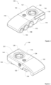
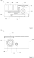
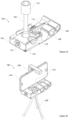
- FIGS. 1-14 show various views of an exemplary embodiment of a skateboard tool 100 in its assembled form.
- FIGS. 1-4 are different top perspective views of the tool 100
- FIGS. 5-8 are different bottom perspective views of the tool 100
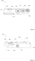
- FIG. 9 is a top view of the tool 100
- FIG. 10 is a bottom view of the tool 100
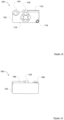
- FIG. 11 is a front view of the tool 100
- FIG. 12 is a back view of the tool 100
- FIG. 13 is a left side view of the tool 100
- FIG. 14 is a right side view of the tool.
- the illustrated embodiment of the skateboard tool 100 generally includes, without limitation: a case 102; a bar extension tool 104; three socket tools 106, 108, 110 of various sizes; a wrench tool 112; a razor blade 114; a threading die 116; a file 118; a drive ratchet 120; threaded inserts 122, 124; a ratchet cap 126; and a spring clip 128.
- the case 102 is shaped, formed, and otherwise configured to accommodate and removably hold a number of tools and components that are useful to skateboarders.
- the case 102 can be formed from injection molded plastic, or any similar material. In preferred implementations the case 102 can be a single-piece component or it can be formed from multiple components that are bonded or glued or secured together.
- the case 102 includes different structural features, cavities, slots, grooves, holes, tabs, and the like to receive and removably hold the individual tools such that any given tool can be removed for use and returned to the case 102 for storage, handling, and travel.
- the bar extension tool 104 can be removed from its stored position so that its female end can be installed onto the fitting of the drive ratchet 120, which is a square fitting for this particular embodiment (see FIG. 19 ).
- the socket tools 106, 108, 110 are compatible with the male end of the bar extension tool 104. Any of the socket tools 106, 108, 110 can be removed from their stored location on the case 102, and installed onto the male end of the bar extension tool 104.
- the case 102 can then be utilized as a handle to actuate the drive ratchet 120 for purposes of tightening/loosening nuts that are commonly used on a skateboard.
- the socket tool 106 is sized 3/8 inch for adjustment of truck mounting hardware
- the socket tool 108 is sized 1/2 inch for adjustment of axle nuts
- the socket tool 110 is sized 9/16 inch for adjustment of the truck kingpin nut.
- the case 102 also includes a feature to secure the wrench tool 112 when not in use.
- the wrench tool 112 can be an L-shaped wrench having one end configured as an allen wrench, and having the other end configured as a phillips head screwdriver.
- the wrench tool 112 can include any suitable end configuration (flathead screwdriver, star-shaped pattern, etc.). Both ends are compatible with commonly used truck mounting bolts/screws.
- the case 102 also includes a slot to secure the razor blade 114 when not in use.
- the razor blade 114 is maintained in the case via the spring clip 128, which adds tension on one side of the razor blade 114, pressing it against the interior of the slot.
- the razor blade 114 is useful for installing sheets of adhesive grip tape on a skateboard deck.
- the file 118 which is attached to a side corner of the case 102, is useful when installing sheets of grip tape on a skateboard deck.
- the tool 100 can be held while the file 118 is scraped against grip tape at the edge of the skateboard deck to make cutting of the excess grip tape (using the razor blade 114) easier and cleaner.
- the die 116 is preferably affixed in one end of the case 102.
- the die 116 includes cutting threads that are sized to match the standard thread size used on conventional skateboard truck axles. Rotation of the die 116 forms or repairs external threads.
- the die 116 is particularly useful to rethread damaged ends of truck axles when necessary to replace the skateboard wheels. To this end, the die 116 and its corresponding mounting cavity are designed and configured to provide enough space/clearance to receive and accommodate the end of a truck axle.
- the threaded insert 122 is located on the back side of the tool 100.
- the threaded insert 122 is configured to receive a thumb screw 218 that in turn secures a phone mount to the side of the case 102 (see FIGS. 20-25 ).
- the threaded insert 124 is located on the bottom side of the tool 100.
- the threaded insert 124 is configured to receive a threaded tip 228 of a tripod 200 (see FIG. 23 ).
- the threaded inserts 122, 124 and/or other threaded inserts can also be used to attach other accessories, tools, or components to the case 102 if so desired.
- the fitting of the drive ratchet 120 is exposed at the top side of the case 102.
- the drive ratchet 120 includes a toggle switch 121, which is exposed at the bottom side of the case 102.
- the drive ratchet 120 may also include a button release feature for purposes of removing compatible tools from its fitting.
- the toggle switch 121 is manipulated (turned clockwise or counterclockwise) to change the direction of the drive ratchet 120 - to tighten or loosen the nuts.
- the ratchet cap 126 is realized as a clip-in or screw-in part to secure and hold the drive ratchet 120 within the case 102. As clearly shown in FIGS.
- the drive ratchet 120 is installed in a longitudinally offset location of the case 102 (i.e., biased toward the right side or the left side) such that the case 102 serves as an efficient and effective moment arm when the drive ratchet 120 is used.
- the offset position of the drive ratchet 120 enables the user to efficiently apply torque to nuts while using the case 102 as a handle.
- the tool 100 is relatively compact and easy to carry, and all of the removable tools are readily accessible from the outside of the case 102, and are easy to remove and replace as needed.
- the tool 100 is appropriately shaped and sized to function as a handle to provide a good grip and leverage when using the socket tools 106, 108, 110, when using the die 116, and when using the file 118.
- the tool 100 is shaped to provide a comfortable grip with its ergonomic design.
- the bottom side of the case 102 is relatively smooth and contoured to fit the user's hand when the case 102 is used as a handle for the drive ratchet 120.
- the size of the tool 100 is compact, which provides the benefit of being comfortable to carry in a pocket, backpack, gear bag, etc.
- FIG. 15 is an exploded perspective view of the skateboard tool 100.
- FIG. 15 shows the case 102 by itself, with the other parts removed therefrom.
- FIG. 15 shows the bar extension tool 104 and its corresponding retaining feature (which is integrally formed in the top side of the case 102 for this embodiment), the wrench tool 112 and its corresponding retaining feature (which is integrally formed in the top side of the case 102 for this embodiment), and all three socket tools 106, 108, 110 and their corresponding retaining features (which are integrally formed in the top and front sides of the case 102 for this embodiment).
- These retaining features are suitably designed and configured to allow the tools to be removed from the case 102 and returned to the case 102 on demand as needed.
- these retaining features are shaped, sized, and otherwise configured to secure the tools to the case in a removable or releasable manner.
- FIG. 15 also shows the die 116 and the file 118 separated from the case 102. However, after assembly and manufacturing, the die 116 and the file 118 are intended to remain in place and are not designed to be easily removed from the case 102.
- FIG. 15 shows the cavity that receives the die 116 and the slotted receptacle that receives the file 118 in accordance with this particular embodiment.
- FIG. 15 also shows o-rings 130 that are located on stems (formed in the case 102) to help hold the socket tools 106, 108, 110 in place. More specifically, for the illustrated embodiment, each stem includes two circumferential grooves that receive the o-rings 130.
- the o-rings 130 are sized to provide a press/friction fit for the socket tools 106, 108, 110. It should be appreciated that the die 116, the file 118, and the socket tools 106, 108, 110 can be secured to the case 102 using alternative and/or additional structures or features than those shown in the figures, as desired for the particular implementation. Some of the features shown in FIG. 15 are described in more detail below with reference to other figures.
- FIG. 16 is a perspective top view of the case 102 of the skateboard tool 100, showing a spring clip 128 removed therefrom.
- FIG. 16 illustrates a retaining feature integrally formed in the case 102 for receiving the spring clip 128.
- the spring clip 128 snaps in place into the case 102 and engages structure of the case 102 to hold itself in place.
- FIG. 16 depicts an exemplary embodiment of the spring clip 128, although other types can also be used.
- the spring clip 128 functions to secure the razor blade 114 in the case 102 for storage.
- FIG. 17 is a perspective bottom view of the skateboard tool 100, showing the following components removed therefrom: the two threaded inserts 122, 124; the drive ratchet 120; and the ratchet cap 126.
- the threaded inserts 122, 124 can be installed via an interference fit, by an adhesive, by a hot melting process, by a molding process, or the like.
- the drive ratchet is inserted into the bottom of the case as shown in FIG. 17 , and twisted to engage a retaining slot or collar.
- the ratchet cap 126 is installed overlying the drive ratchet 120 to hold the drive ratchet 120 in place within the case 102.
- the case 102 and its features can be designed as needed for compatibility with different types of drive ratchet assemblies, and the embodiment shown represents only one suitable possibility.
- FIG. 18 is a top perspective view of the skateboard tool 100, showing the razor blade 114 and a set screw 150 removed therefrom.
- the razor blade 114 is held within a suitably shaped and sized slot formed in the case 102, and is held in place with the spring clip 128 (hidden from view in FIG. 18 ).
- the sharp edge of the razor blade 114 is inserted into the case 102 to keep it well protected.
- the set screw 150 is used in this implementation to hold the die 116 in place within the case 102 and to prevent the die 116 from rotating during use. In certain embodiments, the set screw 150 need not be used - the die 116 can be held in place using other components, an adhesive, or the like.
- FIG. 19 is a top perspective view of the skateboard tool 100 with the socket tool 110 and bar extension tool 104 attached to the drive ratchet 120 (hidden from view).
- the fitting of the drive ratchet 120 is compatible with the female end of the bar extension tool 104 and with the female end of each of the socket tools 106, 108, 110. Accordingly, the fitting of the drive ratchet 120 is suitably configured to receive the socket tools 106, 108, 110 and the bar extension tool 104 for the sockets as needed.
- the tool 100 can be used as a socket driver to tighten or loosen the kingpin nut on the skateboard truck.
- the bar extension tool 104 should be long enough to provide sufficient clearance between the truck mounting baseplate (where the truck mounting nuts are located) and the outer contact surface of the skateboard wheels - to allow the user to install and remove the truck mounting nuts without interference.
- the bar extension tool 104 is three inches long to provide the desired amount of clearance.
- the exact length of the bar extension tool 104 can be more or less than three inches, as appropriate to the particular application.
- the bar extension tool 104 when the bar extension tool 104 is installed on the fitting of the drive ratchet 120, the bar extension tool 104 is perpendicular (or nearly perpendicular, as practical) to the major plane that is defined by the case 102.
- This perpendicular arrangement allows the case 102 to serve as a moment arm to efficiently apply torque to the bar extension tool 104 as needed.
- the perpendicular arrangement also allows the bar extension tool 104 to serve as a lever/handle when the threading die 116 is in use.
- the user can hold the case 102 with one hand, and the bar extension tool 104 with the other hand, while rotating the case 102 (and the threading die 116) around the axle.
- the socket tool 110 can be replaced with the other socket tools 106, 108 if needed for adjustment of the truck mounting hardware or axle nuts. After use, the socket tool 110 can be returned to the appropriate retaining feature of the case 102. Likewise, the bar extension tool 104 can be returned to its respective retaining feature on the case 102.
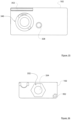
- FIGS. 20-25 show an enhanced feature of the skateboard tool 100.
- FIGS. 20-25 show a phone mount arm 206 that removably attaches to the case 102 to hold a mobile device (e.g., a cell phone, a camera, a video game device) in place.
- FIGS. 20-23 also show a tripod 200 that removably attaches to the bottom of the case 102 to support the tool 100 when it is used as a phone mount as shown.
- FIG. 20 is a front perspective view of the skateboard tool 100 being used as a phone mount
- FIG. 21 is a back perspective view of the skateboard tool 100 being used as a phone mount
- FIG. 22 is a front perspective view of the skateboard tool 100, showing the manner in which a phone can be introduced for holding
- FIG. 23 is an exploded perspective view of the skateboard tool 100, with its phone mount components
- FIG. 24 is a back perspective view of the skateboard tool 100, with the phone mount in its stored position
- FIG. 25 is a bottom view of the skateboard tool 100, with the phone mount in its stored position.
- FIGS. 20 and 21 demonstrate how the mount arm 206 is designed and configured to hold a mobile device in an orientation that is intended to support a camera function of the mobile device.
- the phone mounting feature cooperates with two primary components: the mounting assembly (which includes the phone mount arm 206, and a slider pad 214 movably coupled to the phone mount arm 206); and the tripod 200.
- the tripod 200 includes the threaded tip 228 so that the tripod 200 can be threaded into the threaded insert 124 of the case 102. This allows the case 102 to serve as a support platform for a phone 210 (or any suitably sized mobile device).
- the tripod 200 (when threaded into the threaded insert 124) also functions as a handle to make it easier for the user to take pictures and videos when a phone or other camera-featured device is held by the phone mount arm 206.
- a videographer can hold onto the legs of the tripod 200 while capturing video of a skateboarder.
- This handle option is especially useful for "follow filming" during which the videographer skateboards near or behind a skateboarder who is being filmed.
- the case 102 could also include a feature or an additional component designed to hold or store the tripod 200 when not in use.
- the phone mount arm 206 is held in the desired clamping position overlying the edge of the phone 210 (see FIGS. 20 and 21 ) and is secured in place by way of the thumb screw 218, which, when screwed into the threaded insert 122, maintains the phone mount arm 206 in the secured orientation and position.
- the phone mount arm 206 includes a longitudinally oriented slot 208 formed therein (see FIG. 24 for a clear view of the slot 208) that receives the thumb screw 218.
- the thumb screw 218 is loose, the phone mount arm 206 can freely slide up and down by way of the slot 208. This allows the user to adjust the clamping position and force of the phone mount arm 206 on the top edge of the phone 210.
- the thumb screw 218 can be tightened to secure the phone 210 to the case 102.
- the slider pad 214 is also slidably coupled to the phone mount arm 206 by way of the slot 208.
- the slider pad 214 may include a key/keyway feature or a snap-fit feature that allows it to be attached and retained within the slot 208 in a way that still allows it to slide freely as needed.
- the slider pad 214 is retained within the slot 208 (above the screwed-in position of the thumb screw 218) such that it can move up and down as needed.
- the slider pad 214 can be formed from a soft resilient material such as rubber to protect the bottom edge of the phone 210 and to provide a secure support platform for the phone 210.
- the bottom edge of the phone 210 rests against the slider pad 214, and the top edge of the phone 210 rests against a resilient pad of the phone mount arm 206, such as an adhesive rubber pad 224 that is affixed to the lower surface of the horizontal extension of the phone mount arm 206.
- the slider pad 214 is an optional element that need not be used.
- the mount arm 206 can be used by itself to clamp the phone 210 directly against a surface or a feature of the case 102 and/or against one or more of the tools held in the case 102.
- the bottom edge of the phone 210 can be positioned to rest against a surface, a feature, or a tool to achieve a desired orientation or camera angle.
- Skateboarders are notorious for capturing video and picture footage of themselves and others while performing daring skateboard tricks.
- the phone mounting and tripod feature of the tool 100 makes it easy and convenient to set up a mobile phone in a safe, secure, and stable manner. Accordingly, this feature adds fundamental benefits to the skateboard tool 100. This is the very first skateboard tool to incorporate filming capabilities in use with a skateboard tool.
- the phone mount arm 206 can be stored in a compact manner on one side of the case 102. As shown in these figures, the L-shape of the phone mount arm 206 follows the outer perimeter of the case 102, the slider pad 214 is moved to an uppermost position on the phone mount arm 206, and the thumb screw 218 is tightened into the threaded insert 122 to hold the phone mount arm 206 in place. Alternatively, the user can store the phone mount arm 206 separately from the case 102 if so desired.
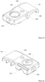
- FIGS. 26-36 are different views of the case 102 by itself. More specifically, FIGS. 26-29 are different top perspective views of the case 102 of the skateboard tool 100, FIGS. 30-33 are bottom perspective views of the case 102, FIG. 34 is a top view of the case 102, FIG. 35 is a bottom view of the case 102, and FIG. 36 is a left side view of the case 102.
- This set of figures depicts the case 102 alone, without any tools or components installed therein.
- a first retaining feature 302 is shaped, sized, and configured to accommodate the bar extension tool 104 by way of a snap-fitting engagement. Accordingly, the first retaining feature 302 functions as a bar extension retaining feature that is suitably configured to secure the bar extension tool 104 to the case in a removable manner. In this regard, the bar extension tool 104 can be removably coupled to the case via the bar extension retaining feature.
- the first retaining feature 302 includes a plurality of tabs 304 (e.g., four tabs) that impart clamping force to the sides of the bar extension tool 104 when the bar extension tool 104 is seated and secured within the first retaining feature 302.
- the four tabs 304 are positioned at the uppermost ends of the first retaining feature 302, and each tab 304 protrudes inward.
- the first retaining feature 302 is designed such that the bar extension tool 104 can be easily removed as needed by pulling on the bar extension tool 104.
- the first retaining feature 302 is located on the top of the case 102, and at or near the back side of the case 102. In other embodiments, the first retaining feature 302 can be located elsewhere on the case 102.
- the case 102 includes a finger slot 306 formed therein to make it easier for the user to remove the bar extension tool 104.
- the finger slot 306 is realized as a shallow indentation located at one end of the first retaining feature 302.
- the finger slot 306 is shaped, sized, and located such that a gap is formed underlying an end of the bar extension tool 104 when the bar extension tool 104 is seated in its stored position (see FIGS. 3, 4 , 7 , and 12 ).
- the finger slot 306 allows the user to slide a fingertip under the end of the bar extension tool 104 to easily release the bar extension tool 104 from the first retaining feature 302.
- the case 102 also includes a second retaining feature 309 for the wrench tool 112.
- the second retaining feature 309 functions as a wrench retaining feature that is suitably configured to secure the wrench tool 112 to the case in a removable manner.
- the second retaining feature 309 is shaped, sized, and configured to accommodate the wrench tool 112 by way of a snap-fitting engagement along one arm of the wrench tool 112.
- the second retaining feature 309 includes a wrench hole 312 to receive a tip/end of the wrench tool 112 (see FIG. 26 and FIG. 39 , which is a cross section that shows the wrench hole 312).
- the wrench hole 312 is configured to receive the allen head end of the wrench tool 112.
- the second retaining feature 309 includes at least one protrusion or tab 310 that imparts clamping force to one or more sides of the wrench tool 112 when the wrench tool 112 is seated and secured within the second retaining feature 309.
- the case 102 includes a relief slot 314 formed behind the tab 310, as best shown in FIGS. 28 , 29 , and 34 .
- the relief slot 314 creates a resilient wall for the tab 310; the wall flexes by a desired amount to provide the required clamping force for the tab 310.
- the second retaining feature 309 is located on the top of the case 102, in an approximately central position. When installed, the primary arm of the wrench tool 112 is parallel to the bar extension tool 104, as depicted in FIG. 9 . In other embodiments, the second retaining feature 309 can be located elsewhere on the case 102.
- the wrench tool 112 is installed (and removably coupled to) the case 102 via the wrench retaining feature in the following manner. First, the allen head end of the wrench tool 112 is inserted into the wrench hole 312 to position one end of the wrench tool 112. Next, the primary arm of the wrench tool 112 is rotated downward into the second retaining feature 309 until it engages the tab 310. The force imparted by the tab 310 holds the wrench tool 112 in place.
- the finger slot 306 also helps the user during removal of the wrench tool 112.
- the finger slot 306 is shaped, sized, and located such that a gap is formed underlying an end of the wrench tool 112, namely, the phillips head end of the wrench tool 112.
- the finger slot 306 allows the user to slide a fingertip under the end of the wrench tool 112 to pry the wrench tool 112 from the second retaining feature 309.
- the finger slot 306, the first retaining feature 302, and the second retaining feature 309 are cooperatively configured such that the wrench tool 112 and the bar extension tool 104 can be easily removed from the case 102 independently from one another.
- the free end of the wrench tool 112 extends further toward the right side of the case, relative to the free end of the bar extension tool 104. This arrangement allows the user to selectively remove only the wrench tool 112 without having to also remove the bar extension tool 104, and vice versa.
- the wrench hole 312 is optional.
- the second retaining feature 309 can utilize additional tabs, compression features, or the like to releasably retain the wrench tool 112 in place without the use of the wrench hole 312.
- the case 102 may include a hole to receive the longer end of the wrench tool 112, along with a slot or cavity to receive the perpendicular (shorter) end of the wrench tool 112, such that the wrench tool 112 can be inserted into the case 102 and held in place by way of a press-fitting engagement, retaining features, a snap-fit, or the like.
- the case 102 also includes third retaining features 318 for the socket tools 106, 108, 110.
- Each of the third retaining features 318 functions as a socket retaining feature that is suitably configured to secure a respective socket to the case in a removable manner.
- Each of the third retaining features 318 is shaped, sized, and configured to accommodate one of the three socket tools.
- the case 102 includes three differently sized versions of the third retaining feature 318.
- the third retaining features 318 are located on the front side of the case 102, at or near the right side. In other embodiments, the third retaining features 318 can be located elsewhere on the case 102.
- each of the third retaining features 318 is similarly designed and configured to removably hold a respective socket tool.
- each retaining feature 318 includes a partially cylindrical cavity 320 formed in the front side of the case 102, and a stem 322 protruding from the base of the partially cylindrical cavity 320.
- the stem 322 is positioned at what would be the center of the round cylindrical base.
- Each stem 322 has two circumferential grooves formed therein to receive two o-rings 130 (see FIG. 15 ), although more or less than two o-rings 130 can be utilized.
- the third retaining feature 318 holds its socket in place by a combination of compression of the o-ring 130 within the ratchet drive fitting end of the socket, in addition to slight friction or interference fit associated with the interior surface of the partially cylindrical cavity 320.
- the sockets are somewhat tightly fitted within their respective cavities 320.
- socket tools can be removably secured to the case 102 using magnets, snap-fitting features, a friction fit, clips, hold-down elements, or the like.
- the preferred embodiment utilizes partially cylindrical cavities 320 rather than fully cylindrical cavities so that a portion of each socket tool (when properly installed in the cavities 320) remains exposed and protruding slightly above the major top surface of the case 102. This enables the user to easily push the sockets out from the third retaining features 318 as needed. See FIGS 1-4 , which show the top edges of the socket tools 106, 108, 110 exposed and accessible.
- the partially cylindrical cavities have a depth that approximates the height of the socket tools 106, 108, 110. Consequently, when the sockets are properly installed in (and removably coupled to) the case 102, they do not protrude significantly from the front side of the case 102 (see FIG. 1 and FIG. 2 ). This results in a clean look, a comfortable carry, and comfortable use.
- FIG. 30 and FIG. 31 both depict insert holes 328, which are shaped, sized, and configured to accommodate the threaded inserts 122, 124 (as described above).
- One insert hole 328 is formed in the back side of the case 102, and the other insert hole 328 is formed in the bottom of the case 102.
- the threaded inserts 122, 124 are maintained in the insert holes 328 by way of a press-fit engagement, bonding, welding, an adhesive, molding, or the like.
- FIG. 31 and FIG. 32 both depict a die cavity 332, which is shaped, sized, and configured to accommodate and hold the die 116 (as described above).
- the die cavity 332 is formed in the left side of the case 102. In other embodiments, the die cavity 332 can be located elsewhere on the case 102.
- the die cavity 332 can be shaped to match the outer perimeter shape of the die 116, e.g., hexagonal.
- the set screw 150 can be used to hold the die 116 within the die cavity 332.
- the die 116 can be installed in the case 102 by way of a press-fit engagement, bonding, welding, an adhesive, molding, or the like.
- the die cavity 332 includes a counterbore 334 formed in the case 102 (see FIG. 36 ).
- the counterbore 334 is desirable to provide additional clearance behind the die 116 to accommodate skateboard truck axles during thread repair using the die 116.
- the case 102 includes a suitably configured ratchet cavity 340 for the drive ratchet 120.
- the ratchet cavity 340 is formed in the bottom side of the case 102, however, the ratchet cavity 340 includes a portion that extends all the way through the case 102. In other embodiments, the ratchet cavity 340 can be located elsewhere on the case 102.
- the ratchet cavity 340 can include any number of features, structures, or elements as needed for compatibility with the specific design and specifications of the drive ratchet 120.
- the drive ratchet 120 can be an offthe-shelf component, and the ratchet cavity 340 can be suitably designed and configured as needed to match the chosen drive ratchet 120 part.
- the exemplary drive ratchet 120 includes two extending nubs that are received in two corresponding keyway features of the ratchet cavity 340.
- the ratchet cap 126 is installed overlying the drive ratchet 120.
- the ratchet cap 126 is installed using an interference fit, and it locks the drive ratchet 120 in place by preventing rotation of the nubs within the keyway features.
- the razor blade retaining feature of the tool 100 will now be described with particular reference to FIG. 34 (a top view of the case 102), FIG. 37 (a cross sectional view taken along line B-B of FIG. 34 , showing the razor blade 114 in place), and FIG. 38 (a cross sectional view taken along line B-B, in the absence of the razor blade 114).
- the case 102 includes a razor blade slot 344 integrally formed therein, and shaped, sized, and configured to receive a standard single-edged razor blade.
- the razor blade slot is formed in the top of the case 102, and it is located near the front and left sides of the case 102. In other embodiments, the razor blade slot 344 can be located elsewhere on the case 102. As shown in FIG. 37 and FIG.
- the razor blade slot 344 is slightly angled from the front to the back of the case.
- the spring clip 128 is exposed within the razor blade slot 344 such that it can engage with the side of the razor blade 114 and impart a sideways force to hold the razor blade 114 in place. In this way, the spring clip 128 cooperates with the razor blade slot 344 to safely secure the razor blade 114 to the case 102 in a removable manner.
- the case 102 also includes a finger groove 348 that intersects the razor blade slot 344.
- the finger groove 348 is shaped, sized, and positioned (relative to the razor blade slot 344) to leave the top non-sharp portion of the razor blade 114 exposed when it is inserted in the razor blade slot 344, as shown in FIGS. 1-4 . This makes it easier to grab the top of the razor blade 114 when removing and inserting it.
- the spring clip 128 imparts sideways force against the razor blade 114 when the blade 114 is properly installed in the razor blade slot 344, as depicted in FIG. 37 .
- the spring clip 128 is designed with sufficient tension to retain the razor blade 114 safely within the slot 344 when not in use. It should be appreciated that other retaining elements, schemes, or mechanisms can be utilized instead of the spring clip 128 if so desired. For example, a secure latch, a pin, a cover, or other features could be implemented.
- the case 102 also includes a retaining key 352 for the file 118.
- the retaining key 352 is formed in the front-bottom corner edge of the case 102, at the left side of the case 102. In other embodiments, the retaining key 352 can be located elsewhere on the case 102. Attaching the file 118 at or near an edge of the case 102 is desirable for ergonomic and effective use of the file 118.
- the retaining key 352 is shaped and sized to fit the file 118, which in this embodiment is implemented as a slotted roll pin, which may (but need not) have an abrasive outer surface. Accordingly, the retaining key 352 has a generally cylindrical head that is offset from the corner edge of the case 102.
- the file 118 can be installed onto the retaining key 352 from the exposed side of the key 352, as demonstrated in FIG. 15 .
- the outer diameter of the cylindrically shaped portion of the retaining key 352 matches the inner diameter of the file 118 such that the file 118 is retained on the case 102 by way of an interference friction fit.
- an adhesive or a hot melt process could be used to further strengthen the coupling of the file 118 to the retaining key 352. Regardless of how the file 118 is attached or secured to the case, at least a portion of its working surface remains exposed, as shown in the figures.
- the file 118 can be realized as a simple dowel pin (e.g., a solid metal shaft) rather than a slotted roll pin.
- the file 118 can be secured into a suitably shaped and sized slot or cavity formed in the case 102 by a press-fit engagement, an adhesive, or the like, such that a portion of the outer surface of the file 118 remains exposed.
- the file 118 can be realized as a threaded pin that is screwed into the case 102, which is cooperatively configured such that some of the outer surface of the file 118 remains exposed, as described above.
Landscapes
- Engineering & Computer Science (AREA)
- Mechanical Engineering (AREA)
- Purses, Travelling Bags, Baskets, Or Suitcases (AREA)
- Telephone Set Structure (AREA)
- Automatic Tool Replacement In Machine Tools (AREA)
Abstract
Description
- This application claims the benefit of
United States provisional patent application number 62/538,886, filed July 31, 2017 - Embodiments of the subject matter described herein relate generally to multi-function tools and accessories of the type used for skateboards.
- Skateboarding is a wonderful sport that has become more popular with America's youth than little league baseball, Pop Warner football, and other traditional sporting activities. A skateboard includes the following fundamental components: a deck; four wheels; and two trucks that attach the wheels to the deck and which serve as turning mechanisms for the skateboard. Each truck is attached to the deck using nuts and bolts, and each wheel is attached to the threaded end of a truck axle using a nut. The turning responsiveness of each truck is adjustable by tightening or loosening a kingpin nut. Accordingly, assembly, maintenance, and adjustment of a skateboard requires a variety of tools (e.g., screwdrivers, wrenches, sockets, or the like).
- The prior art is replete with different types of skateboard tools. Many skateboard tools are "all-in-one" designs that include features that are specifically sized and configured for standard sized truck mounting hardware, axle nuts, and kingpin nuts. Although conventional skateboard tool designs may be convenient and/or compact, those benefits can be outweighed by various shortcomings and deficiencies. For example, some low-cost skateboard tools break easy or have parts that wear out too soon. As another example, traditional skateboard tools may be cumbersome and difficult to use, which can be bothersome when quick adjustment or assembly is required.
- Accordingly, there is a need for an improved skateboard tool that is robust, reliable, easy to use, and well-functioning. Furthermore, other desirable features and characteristics of the present invention will become apparent from the subsequent detailed description and the appended claims, taken in conjunction with the accompanying drawings and the foregoing technical field and background.
- A multi-function tool is disclosed. An embodiment of the tool includes: a case having a top side, a bottom side, a front side, a back side, a right side, and a left side; a drive ratchet installed in a ratchet cavity formed in the case, the drive ratchet comprising a fitting exposed at the top side of the case and further comprising a toggle switch exposed at the bottom side of the case, wherein manipulation of the toggle switch changes direction of the drive ratchet, and wherein the fitting is configured to receive sockets and a bar extension for the sockets; a threading die held within a die cavity formed in the case, the threading die comprising cutting threads to form or repair external threads; a file attached to the case such that at least a portion of a working surface of the file is exposed; a wrench retaining feature integrally formed in the case, the wrench retaining feature configured to secure a wrench to the case in a removable manner; a plurality of socket retaining features integrally formed in the case, each of the socket retaining features configured to secure a respective socket to the case in a removable manner; and a bar extension retaining feature integrally formed in the case, the bar extension retaining feature configured to secure a bar extension to the case in a removable manner.
- In an embodiment, the file is attached at or near an edge of the case. In an embodiment, the tool further comprises a wrench tool removably coupled to the case via the wrench retaining feature, a plurality of different sized socket tools removably coupled to the case via the plurality of socket retaining features, and a bar extension tool removably coupled to the case via the bar extension retaining feature, wherein the drive ratchet and the fitting are compatible with the socket tools and the bar extension tool. In an embodiment, the tool further comprises a razor blade slot integrally formed in the case, the razor blade slot configured to receive a razor blade. In an embodiment, the tool further comprises a spring clip attached to the case, wherein the spring clip cooperates with the razor blade slot to secure the razor blade to the case in a removable manner. In an embodiment, the tool further comprises a mount arm removably attached to the case, the mount arm configured to hold a mobile device in place on the case in an orientation intended to support a camera function of the mobile device. In an embodiment, the mount arm comprises a slot formed therein to accommodate adjustment of the mount arm relative to the case, the tool further comprises a thumb screw and a threaded insert located on the case, the threaded insert configured to receive the thumb screw, and the slot receives the thumb screw to facilitate adjustment of a clamping position of the mount arm, such that tightening of the thumb screw secures the mobile device to the case. In an embodiment, the tool further comprises a tripod having a threaded tip, and a threaded insert located on the case, the threaded insert configured to receive the threaded tip of the tripod. In an embodiment, the drive ratchet is installed in a longitudinally offset location of the case such that the case serves as a moment arm when the drive ratchet is used. In an embodiment, the tool further comprises a finger slot formed in the case at an end of the bar extension retaining feature, the finger slot forming a gap underlying an end of a bar extension tool seated in the bar extension retaining feature. In an embodiment, the tool further comprises a finger slot formed in the case at an end of the wrench retaining feature, the finger slot forming a gap underlying an end of a wrench tool seated in the wrench retaining feature. In an embodiment, the drive ratchet and fitting are oriented to hold a bar extension tool substantially perpendicular to the case.
- An embodiment of a multi-function tool includes: a case having a top side, a bottom side, a front side, a back side, a right side, and a left side; a drive ratchet installed in a ratchet cavity formed in the case, the drive ratchet comprising a fitting exposed at the top side of the case and further comprising a toggle switch exposed at the bottom side of the case, wherein manipulation of the toggle switch changes direction of the drive ratchet; a threading die held within a die cavity formed in the case, the threading die comprising cutting threads to form or repair external threads; a file attached to the case such that at least a portion of a working surface of the file is exposed; a wrench retaining feature integrally formed in the case; a wrench tool configured to be removably held by the wrench retaining feature; a plurality of socket retaining features integrally formed in the case; a plurality of socket tools configured to be removably held by the plurality of socket retaining features; a bar extension retaining feature integrally formed in the case; and a bar extension tool configured to be removably held by the bar extension retaining feature, wherein the drive ratchet and the fitting are compatible with the socket tools and the bar extension tool.
- In an embodiment, the tool further comprises a razor blade slot integrally formed in the case, the razor blade slot configured to receive a razor blade. In an embodiment, the tool further comprises a spring clip attached to the case, wherein the spring clip cooperates with the razor blade slot to secure the razor blade to the case in a removable manner. In an embodiment, the tool further comprises a mount arm removably attached to the case, the mount arm configured to hold a mobile device in place on the case in an orientation intended to support a camera function of the mobile device. In an embodiment, the tool further comprises a tripod having a threaded tip, and a threaded insert located on the bottom side of the case, the threaded insert configured to receive the threaded tip of the tripod. In an embodiment, the tool further comprises a finger slot formed in the case at an end of the bar extension retaining feature, the finger slot forming a gap underlying an end of the bar extension tool when seated in the bar extension retaining feature, and underlying an end of the wrench tool when seated in the wrench retaining feature. In an embodiment, the drive ratchet and fitting are oriented to hold the bar extension tool substantially perpendicular to the case.
- An embodiment of a multi-function tool includes: a case having a top side, a bottom side, a front side, a back side, a right side, and a left side; a drive ratchet installed in a ratchet cavity formed in the case, the drive ratchet comprising a fitting exposed at the top side of the case and further comprising a toggle switch exposed at the bottom side of the case, wherein manipulation of the toggle switch changes direction of the drive ratchet; a threading die held within a die cavity formed in the case, the threading die comprising cutting threads to form or repair external threads; a file attached to the case such that at least a portion of a working surface of the file is exposed; a wrench tool removably secured to the case by a wrench retaining feature integrally formed in the case; a plurality of socket tools removably secured to the case by a plurality of socket retaining features integrally formed in the case; and a bar extension tool removably secured to the case by a bar extension retaining feature integrally formed in the case, wherein the bar extension tool is compatible with the socket tools, the fitting of the drive ratchet is compatible with the socket tools, and the fitting of the drive ratchet is compatible with the bar extension tool.
- This summary is provided to introduce a selection of concepts in a simplified form that are further described below in the detailed description. This summary is not intended to identify key features or essential features of the claimed subject matter, nor is it intended to be used as an aid in determining the scope of the claimed subject matter.
- A more complete understanding of the subject matter may be derived by referring to the detailed description and claims when considered in conjunction with the following figures, wherein like reference numbers refer to similar elements throughout the figures.
-
FIGS. 1-4 are different top perspective views of an exemplary embodiment of a skateboard tool; -
FIGS. 5-8 are different bottom perspective views of the skateboard tool; -
FIG. 9 is a top view of the skateboard tool; -
FIG. 10 is a bottom view of the skateboard tool; -
FIG. 11 is a front view of the skateboard tool; -
FIG. 12 is a back view of the skateboard tool; -
FIG. 13 is a left side view of the skateboard tool; -
FIG. 14 is a right side view of the skateboard tool; -
FIG. 15 is an exploded perspective view of the skateboard tool; -
FIG. 16 is a perspective top view of the skateboard tool's case, showing a retaining clip removed therefrom; -
FIG. 17 is a perspective bottom view of the skateboard tool, showing various components removed therefrom; -
FIG. 18 is a top perspective view of the skateboard tool, showing a razor blade and a set screw removed therefrom; -
FIG. 19 is a top perspective view of the skateboard tool with a socket and bar extension attached; -
FIG. 20 is a front perspective view of the skateboard tool being used as a phone mount; -
FIG. 21 is a back perspective view of the skateboard tool being used as a phone mount; -
FIG. 22 is a front perspective view of the skateboard tool, showing the manner in which a phone can be introduced for holding; -
FIG. 23 is an exploded perspective view of the skateboard tool, with its phone mount components; -
FIG. 24 is a back perspective view of the skateboard tool, with the phone mount in its stored position; -
FIG. 25 is a bottom view of the skateboard tool, with the phone mount in its stored position; -
FIGS. 26-29 are top perspective views of the case of the skateboard tool; -
FIGS. 30-33 are bottom perspective views of the case of the skateboard tool; -
FIG. 34 is a top view of the case of the skateboard tool; -
FIG. 35 is a bottom view of the case of the skateboard tool; -
FIG. 36 is a left view of the case of the skateboard tool; -
FIG. 37 is a cross sectional view taken along line B-B shown inFIG. 34 , showing a razor blade in place; -
FIG. 38 is a cross sectional view taken along line B-B shown inFIG. 34 , in the absence of a razor blade; -
FIG. 39 is a cross sectional view taken along line C-C shown inFIG. 34 ; and -
FIG. 40 is a cross sectional view taken along line D-D shown inFIG. 34 . - The following detailed description is merely illustrative in nature and is not intended to limit the embodiments of the subject matter or the application and uses of such embodiments. As used herein, the word "exemplary" means "serving as an example, instance, or illustration." Any implementation described herein as exemplary is not necessarily to be construed as preferred or advantageous over other implementations. Furthermore, there is no intention to be bound by any expressed or implied theory presented in the preceding technical field, background, brief summary or the following detailed description.
- The following description may refer to elements or nodes or features being "connected" or "coupled" together. As used herein, unless expressly stated otherwise, "coupled" means that one element/node/feature is directly or indirectly joined to (or directly or indirectly communicates with) another element/node/feature, and not necessarily mechanically. Likewise, unless expressly stated otherwise, "connected" means that one element/node/feature is directly joined to (or directly communicates with) another element/node/feature, and not necessarily mechanically.
- In addition, certain terminology may also be used in the following description for the purpose of reference only, and thus are not intended to be limiting. For example, terms such as "upper", "lower", "above", and "below" refer to directions in the drawings to which reference is made. Terms such as "front", "back", "rear", "side", "outboard", and "inboard" describe the orientation and/or location of portions of the component within a consistent but arbitrary frame of reference which is made clear by reference to the text and the associated drawings describing the component under discussion. Such terminology may include the words specifically mentioned above, derivatives thereof, and words of similar import. Similarly, the terms "first", "second", and other such numerical terms referring to structures do not imply a sequence or order unless clearly indicated by the context.
- This multi-function skateboard tool is a versatile skateboard tool that consolidates multiple tools into one compact gadget to help skateboarders assemble, maintain, adjust, and repair skateboards. This multi-function skateboard tool acts as an all-in-one skateboard tool as it contains each and every tool needed to be compatible with the various components of a skateboard (e.g., different sized nuts and bolts on a skateboard). The multiple tools this multi-function skateboard tool contains are secured in a casing by their retaining features and are intended to be removed for usage while some tools are intended to remain fixed into the casing. The casing also acts as a handle/lever to be used with the tools when removed and with the tools fixed in the casing. This multi-function skateboard tool offers the benefit of eliminating the need of having to carry multiple tools to assemble, maintain, adjust, and repair skateboards. In addition, this multi-function skateboard tool is designed to offer superior functionality over existing skateboard tools. Skateboards contain various sized nuts that are threaded onto bolts holding various skateboard components together and require the nuts to be tightened/loosened with properly sized socket tools for assembly, maintenance, adjustments, and repairs. This multi-function skateboard tool contains socket tools with no surrounding material (e.g., plastic moldings) around the outer diameter of the socket tools when in use to prevent clearance issues, providing the socket tools complete unobstructed access to the nuts, and allowing the socket tools to be fully seated onto the nuts. This provides the necessary torque required when tightening/loosening the nuts and prevents the socket tools from slipping off the nuts which is a problem other existing skateboard tools have issues with due to the surrounding material (e.g., plastic molding) around the outer diameter of their socket tools. Another fundamental benefit this multi-function skateboard tool offers is the drive ratchet feature compatible to work with all the various sized socket tools. The drive ratchet feature allows a user of this tool to continuously tum/tighten/loosen/adjust the various sized nuts on a skateboard without having to remove and reposition the sockets onto the nuts after each turn while existing skateboard tools require users to do. The removable tools included in this multi-function skateboard tool are properly secured with the casing retaining features to prevent the removable tools from falling out and getting lost when stored/not in use. This multi-function skateboard tool is the first skateboard tool to incorporate attributes to be used with a filming device (e.g., cell phone) for recording. This multi-function skateboard tool acts as a phone mount to be used with is related accessories (e.g., phone mount arm, tripod stand) to secure a filming device (e.g., cell phone) to be propped up and aimed at a target for capturing videos/pictures.
-
FIGS. 1-14 show various views of an exemplary embodiment of askateboard tool 100 in its assembled form.FIGS. 1-4 are different top perspective views of thetool 100,FIGS. 5-8 are different bottom perspective views of thetool 100,FIG. 9 is a top view of thetool 100,FIG. 10 is a bottom view of thetool 100,FIG. 11 is a front view of thetool 100,FIG. 12 is a back view of thetool 100,FIG. 13 is a left side view of thetool 100, andFIG. 14 is a right side view of the tool. - The illustrated embodiment of the
skateboard tool 100 generally includes, without limitation: acase 102; abar extension tool 104; threesocket tools wrench tool 112; arazor blade 114; athreading die 116; afile 118; adrive ratchet 120; threadedinserts ratchet cap 126; and aspring clip 128. Thecase 102 is shaped, formed, and otherwise configured to accommodate and removably hold a number of tools and components that are useful to skateboarders. Thecase 102 can be formed from injection molded plastic, or any similar material. In preferred implementations thecase 102 can be a single-piece component or it can be formed from multiple components that are bonded or glued or secured together. - As shown in
FIGS. 1-14 , thecase 102 includes different structural features, cavities, slots, grooves, holes, tabs, and the like to receive and removably hold the individual tools such that any given tool can be removed for use and returned to thecase 102 for storage, handling, and travel. In this regard, thebar extension tool 104 can be removed from its stored position so that its female end can be installed onto the fitting of thedrive ratchet 120, which is a square fitting for this particular embodiment (seeFIG. 19 ). Thesocket tools bar extension tool 104. Any of thesocket tools case 102, and installed onto the male end of thebar extension tool 104. Thecase 102 can then be utilized as a handle to actuate thedrive ratchet 120 for purposes of tightening/loosening nuts that are commonly used on a skateboard. More specifically, thesocket tool 106 is sized 3/8 inch for adjustment of truck mounting hardware, thesocket tool 108 is sized 1/2 inch for adjustment of axle nuts, and thesocket tool 110 is sized 9/16 inch for adjustment of the truck kingpin nut. - The
case 102 also includes a feature to secure thewrench tool 112 when not in use. Thewrench tool 112 can be an L-shaped wrench having one end configured as an allen wrench, and having the other end configured as a phillips head screwdriver. Alternatively or additionally, thewrench tool 112 can include any suitable end configuration (flathead screwdriver, star-shaped pattern, etc.). Both ends are compatible with commonly used truck mounting bolts/screws. - The
case 102 also includes a slot to secure therazor blade 114 when not in use. Therazor blade 114 is maintained in the case via thespring clip 128, which adds tension on one side of therazor blade 114, pressing it against the interior of the slot. Therazor blade 114 is useful for installing sheets of adhesive grip tape on a skateboard deck. Likewise, thefile 118, which is attached to a side corner of thecase 102, is useful when installing sheets of grip tape on a skateboard deck. Thetool 100 can be held while thefile 118 is scraped against grip tape at the edge of the skateboard deck to make cutting of the excess grip tape (using the razor blade 114) easier and cleaner. - The
die 116 is preferably affixed in one end of thecase 102. Thedie 116 includes cutting threads that are sized to match the standard thread size used on conventional skateboard truck axles. Rotation of the die 116 forms or repairs external threads. Thedie 116 is particularly useful to rethread damaged ends of truck axles when necessary to replace the skateboard wheels. To this end, thedie 116 and its corresponding mounting cavity are designed and configured to provide enough space/clearance to receive and accommodate the end of a truck axle. - The threaded
insert 122 is located on the back side of thetool 100. The threadedinsert 122 is configured to receive athumb screw 218 that in turn secures a phone mount to the side of the case 102 (seeFIGS. 20-25 ). The threadedinsert 124 is located on the bottom side of thetool 100. The threadedinsert 124 is configured to receive a threadedtip 228 of a tripod 200 (seeFIG. 23 ). The threaded inserts 122, 124 and/or other threaded inserts (not shown) can also be used to attach other accessories, tools, or components to thecase 102 if so desired. - Referring to
FIGS. 1-4 , the fitting of thedrive ratchet 120 is exposed at the top side of thecase 102. Referring toFIGS. 5-8 thedrive ratchet 120 includes atoggle switch 121, which is exposed at the bottom side of thecase 102. Thedrive ratchet 120 may also include a button release feature for purposes of removing compatible tools from its fitting. Thetoggle switch 121 is manipulated (turned clockwise or counterclockwise) to change the direction of the drive ratchet 120 - to tighten or loosen the nuts. Theratchet cap 126 is realized as a clip-in or screw-in part to secure and hold thedrive ratchet 120 within thecase 102. As clearly shown inFIGS. 1-8 , thedrive ratchet 120 is installed in a longitudinally offset location of the case 102 (i.e., biased toward the right side or the left side) such that thecase 102 serves as an efficient and effective moment arm when thedrive ratchet 120 is used. In other words, the offset position of thedrive ratchet 120 enables the user to efficiently apply torque to nuts while using thecase 102 as a handle. - As shown in
FIGS. 1-14 , thetool 100 is relatively compact and easy to carry, and all of the removable tools are readily accessible from the outside of thecase 102, and are easy to remove and replace as needed. Moreover, thetool 100 is appropriately shaped and sized to function as a handle to provide a good grip and leverage when using thesocket tools die 116, and when using thefile 118. In addition, thetool 100 is shaped to provide a comfortable grip with its ergonomic design. To this end, the bottom side of thecase 102 is relatively smooth and contoured to fit the user's hand when thecase 102 is used as a handle for thedrive ratchet 120. The size of thetool 100 is compact, which provides the benefit of being comfortable to carry in a pocket, backpack, gear bag, etc. -
FIG. 15 is an exploded perspective view of theskateboard tool 100.FIG. 15 shows thecase 102 by itself, with the other parts removed therefrom.FIG. 15 shows thebar extension tool 104 and its corresponding retaining feature (which is integrally formed in the top side of thecase 102 for this embodiment), thewrench tool 112 and its corresponding retaining feature (which is integrally formed in the top side of thecase 102 for this embodiment), and all threesocket tools case 102 for this embodiment). These retaining features are suitably designed and configured to allow the tools to be removed from thecase 102 and returned to thecase 102 on demand as needed. In this regard, these retaining features are shaped, sized, and otherwise configured to secure the tools to the case in a removable or releasable manner. -
FIG. 15 also shows thedie 116 and thefile 118 separated from thecase 102. However, after assembly and manufacturing, thedie 116 and thefile 118 are intended to remain in place and are not designed to be easily removed from thecase 102.FIG. 15 shows the cavity that receives thedie 116 and the slotted receptacle that receives thefile 118 in accordance with this particular embodiment.FIG. 15 also shows o-rings 130 that are located on stems (formed in the case 102) to help hold thesocket tools rings 130 are sized to provide a press/friction fit for thesocket tools die 116, thefile 118, and thesocket tools case 102 using alternative and/or additional structures or features than those shown in the figures, as desired for the particular implementation. Some of the features shown inFIG. 15 are described in more detail below with reference to other figures. -
FIG. 16 is a perspective top view of thecase 102 of theskateboard tool 100, showing aspring clip 128 removed therefrom.FIG. 16 illustrates a retaining feature integrally formed in thecase 102 for receiving thespring clip 128. Thespring clip 128 snaps in place into thecase 102 and engages structure of thecase 102 to hold itself in place.FIG. 16 depicts an exemplary embodiment of thespring clip 128, although other types can also be used. Thespring clip 128 functions to secure therazor blade 114 in thecase 102 for storage. -
FIG. 17 is a perspective bottom view of theskateboard tool 100, showing the following components removed therefrom: the two threadedinserts drive ratchet 120; and theratchet cap 126. In practice, the threadedinserts tool 100, the drive ratchet is inserted into the bottom of the case as shown inFIG. 17 , and twisted to engage a retaining slot or collar. Thereafter, theratchet cap 126 is installed overlying thedrive ratchet 120 to hold thedrive ratchet 120 in place within thecase 102. Thecase 102 and its features can be designed as needed for compatibility with different types of drive ratchet assemblies, and the embodiment shown represents only one suitable possibility. -
FIG. 18 is a top perspective view of theskateboard tool 100, showing therazor blade 114 and aset screw 150 removed therefrom. Therazor blade 114 is held within a suitably shaped and sized slot formed in thecase 102, and is held in place with the spring clip 128 (hidden from view inFIG. 18 ). Of course, the sharp edge of therazor blade 114 is inserted into thecase 102 to keep it well protected. Theset screw 150 is used in this implementation to hold thedie 116 in place within thecase 102 and to prevent the die 116 from rotating during use. In certain embodiments, theset screw 150 need not be used - thedie 116 can be held in place using other components, an adhesive, or the like. -
FIG. 19 is a top perspective view of theskateboard tool 100 with thesocket tool 110 andbar extension tool 104 attached to the drive ratchet 120 (hidden from view). The fitting of thedrive ratchet 120 is compatible with the female end of thebar extension tool 104 and with the female end of each of thesocket tools drive ratchet 120 is suitably configured to receive thesocket tools bar extension tool 104 for the sockets as needed. In this state, thetool 100 can be used as a socket driver to tighten or loosen the kingpin nut on the skateboard truck. To accommodate such usage, thebar extension tool 104 should be long enough to provide sufficient clearance between the truck mounting baseplate (where the truck mounting nuts are located) and the outer contact surface of the skateboard wheels - to allow the user to install and remove the truck mounting nuts without interference. In certain embodiments, thebar extension tool 104 is three inches long to provide the desired amount of clearance. Of course, the exact length of thebar extension tool 104 can be more or less than three inches, as appropriate to the particular application. - As shown in
FIG. 19 , when thebar extension tool 104 is installed on the fitting of thedrive ratchet 120, thebar extension tool 104 is perpendicular (or nearly perpendicular, as practical) to the major plane that is defined by thecase 102. This perpendicular arrangement allows thecase 102 to serve as a moment arm to efficiently apply torque to thebar extension tool 104 as needed. The perpendicular arrangement also allows thebar extension tool 104 to serve as a lever/handle when the threading die 116 is in use. More specifically, after the threading die 116 is installed onto the end of the skateboard truck axle, the user can hold thecase 102 with one hand, and thebar extension tool 104 with the other hand, while rotating the case 102 (and the threading die 116) around the axle. - The
socket tool 110 can be replaced with theother socket tools socket tool 110 can be returned to the appropriate retaining feature of thecase 102. Likewise, thebar extension tool 104 can be returned to its respective retaining feature on thecase 102. -
FIGS. 20-25 show an enhanced feature of theskateboard tool 100. In particular,FIGS. 20-25 show aphone mount arm 206 that removably attaches to thecase 102 to hold a mobile device (e.g., a cell phone, a camera, a video game device) in place.FIGS. 20-23 also show atripod 200 that removably attaches to the bottom of thecase 102 to support thetool 100 when it is used as a phone mount as shown. More specifically,FIG. 20 is a front perspective view of theskateboard tool 100 being used as a phone mount,FIG. 21 is a back perspective view of theskateboard tool 100 being used as a phone mount,FIG. 22 is a front perspective view of theskateboard tool 100, showing the manner in which a phone can be introduced for holding,FIG. 23 is an exploded perspective view of theskateboard tool 100, with its phone mount components,FIG. 24 is a back perspective view of theskateboard tool 100, with the phone mount in its stored position, andFIG. 25 is a bottom view of theskateboard tool 100, with the phone mount in its stored position.FIGS. 20 and21 demonstrate how themount arm 206 is designed and configured to hold a mobile device in an orientation that is intended to support a camera function of the mobile device. - With continued reference to
FIGS. 20-25 , the phone mounting feature cooperates with two primary components: the mounting assembly (which includes thephone mount arm 206, and aslider pad 214 movably coupled to the phone mount arm 206); and thetripod 200. Thetripod 200 includes the threadedtip 228 so that thetripod 200 can be threaded into the threadedinsert 124 of thecase 102. This allows thecase 102 to serve as a support platform for a phone 210 (or any suitably sized mobile device). The tripod 200 (when threaded into the threaded insert 124) also functions as a handle to make it easier for the user to take pictures and videos when a phone or other camera-featured device is held by thephone mount arm 206. For example, a videographer can hold onto the legs of thetripod 200 while capturing video of a skateboarder. This handle option is especially useful for "follow filming" during which the videographer skateboards near or behind a skateboarder who is being filmed. Although not shown, thecase 102 could also include a feature or an additional component designed to hold or store thetripod 200 when not in use. - The
phone mount arm 206 is held in the desired clamping position overlying the edge of the phone 210 (seeFIGS. 20 and21 ) and is secured in place by way of thethumb screw 218, which, when screwed into the threadedinsert 122, maintains thephone mount arm 206 in the secured orientation and position. Thephone mount arm 206 includes a longitudinally orientedslot 208 formed therein (seeFIG. 24 for a clear view of the slot 208) that receives thethumb screw 218. Thus, when thethumb screw 218 is loose, thephone mount arm 206 can freely slide up and down by way of theslot 208. This allows the user to adjust the clamping position and force of thephone mount arm 206 on the top edge of thephone 210. After moving thephone mount arm 206 into the proper position relative to thecase 102, thethumb screw 218 can be tightened to secure thephone 210 to thecase 102. - The
slider pad 214 is also slidably coupled to thephone mount arm 206 by way of theslot 208. Theslider pad 214 may include a key/keyway feature or a snap-fit feature that allows it to be attached and retained within theslot 208 in a way that still allows it to slide freely as needed. Theslider pad 214 is retained within the slot 208 (above the screwed-in position of the thumb screw 218) such that it can move up and down as needed. Theslider pad 214 can be formed from a soft resilient material such as rubber to protect the bottom edge of thephone 210 and to provide a secure support platform for thephone 210. When thephone 210 is in the desired mounted position (seeFIG. 20 and21 ), the bottom edge of thephone 210 rests against theslider pad 214, and the top edge of thephone 210 rests against a resilient pad of thephone mount arm 206, such as anadhesive rubber pad 224 that is affixed to the lower surface of the horizontal extension of thephone mount arm 206. - It should be appreciated that the
slider pad 214 is an optional element that need not be used. Instead, themount arm 206 can be used by itself to clamp thephone 210 directly against a surface or a feature of thecase 102 and/or against one or more of the tools held in thecase 102. Indeed, the bottom edge of thephone 210 can be positioned to rest against a surface, a feature, or a tool to achieve a desired orientation or camera angle. - Skateboarders are notorious for capturing video and picture footage of themselves and others while performing daring skateboard tricks. The phone mounting and tripod feature of the
tool 100 makes it easy and convenient to set up a mobile phone in a safe, secure, and stable manner. Accordingly, this feature adds fundamental benefits to theskateboard tool 100. This is the very first skateboard tool to incorporate filming capabilities in use with a skateboard tool. - Referring to
FIGS. 24 and25 , thephone mount arm 206 can be stored in a compact manner on one side of thecase 102. As shown in these figures, the L-shape of thephone mount arm 206 follows the outer perimeter of thecase 102, theslider pad 214 is moved to an uppermost position on thephone mount arm 206, and thethumb screw 218 is tightened into the threadedinsert 122 to hold thephone mount arm 206 in place. Alternatively, the user can store thephone mount arm 206 separately from thecase 102 if so desired. -
FIGS. 26-36 are different views of thecase 102 by itself. More specifically,FIGS. 26-29 are different top perspective views of thecase 102 of theskateboard tool 100,FIGS. 30-33 are bottom perspective views of thecase 102,FIG. 34 is a top view of thecase 102,FIG. 35 is a bottom view of thecase 102, andFIG. 36 is a left side view of thecase 102. This set of figures depicts thecase 102 alone, without any tools or components installed therein. - Referring primarily to
FIGS. 26-36 , afirst retaining feature 302 is shaped, sized, and configured to accommodate thebar extension tool 104 by way of a snap-fitting engagement. Accordingly, thefirst retaining feature 302 functions as a bar extension retaining feature that is suitably configured to secure thebar extension tool 104 to the case in a removable manner. In this regard, thebar extension tool 104 can be removably coupled to the case via the bar extension retaining feature. For this embodiment, thefirst retaining feature 302 includes a plurality of tabs 304 (e.g., four tabs) that impart clamping force to the sides of thebar extension tool 104 when thebar extension tool 104 is seated and secured within thefirst retaining feature 302. For the illustrated embodiment, the fourtabs 304 are positioned at the uppermost ends of thefirst retaining feature 302, and eachtab 304 protrudes inward. Thus, thetabs 304 flex outward when thebar extension tool 104 is pressed down and into thefirst retaining feature 302, and snap back after thebar extension tool 104 is seated to retain thebar extension tool 104 in place. Thefirst retaining feature 302 is designed such that thebar extension tool 104 can be easily removed as needed by pulling on thebar extension tool 104. Although not always required, thefirst retaining feature 302 is located on the top of thecase 102, and at or near the back side of thecase 102. In other embodiments, thefirst retaining feature 302 can be located elsewhere on thecase 102. - The
case 102 includes afinger slot 306 formed therein to make it easier for the user to remove thebar extension tool 104. Thefinger slot 306 is realized as a shallow indentation located at one end of thefirst retaining feature 302. Thefinger slot 306 is shaped, sized, and located such that a gap is formed underlying an end of thebar extension tool 104 when thebar extension tool 104 is seated in its stored position (seeFIGS. 3, 4 ,7 , and12 ). Thefinger slot 306 allows the user to slide a fingertip under the end of thebar extension tool 104 to easily release thebar extension tool 104 from thefirst retaining feature 302. - The
case 102 also includes asecond retaining feature 309 for thewrench tool 112. Accordingly, thesecond retaining feature 309 functions as a wrench retaining feature that is suitably configured to secure thewrench tool 112 to the case in a removable manner. For the illustrated embodiment, thesecond retaining feature 309 is shaped, sized, and configured to accommodate thewrench tool 112 by way of a snap-fitting engagement along one arm of thewrench tool 112. In addition, thesecond retaining feature 309 includes awrench hole 312 to receive a tip/end of the wrench tool 112 (seeFIG. 26 andFIG. 39 , which is a cross section that shows the wrench hole 312). For this embodiment, thewrench hole 312 is configured to receive the allen head end of thewrench tool 112. Thesecond retaining feature 309 includes at least one protrusion ortab 310 that imparts clamping force to one or more sides of thewrench tool 112 when thewrench tool 112 is seated and secured within thesecond retaining feature 309. Thecase 102 includes arelief slot 314 formed behind thetab 310, as best shown inFIGS. 28 ,29 , and34 . Therelief slot 314 creates a resilient wall for thetab 310; the wall flexes by a desired amount to provide the required clamping force for thetab 310. Although not always required, thesecond retaining feature 309 is located on the top of thecase 102, in an approximately central position. When installed, the primary arm of thewrench tool 112 is parallel to thebar extension tool 104, as depicted inFIG. 9 . In other embodiments, thesecond retaining feature 309 can be located elsewhere on thecase 102. - The
wrench tool 112 is installed (and removably coupled to) thecase 102 via the wrench retaining feature in the following manner. First, the allen head end of thewrench tool 112 is inserted into thewrench hole 312 to position one end of thewrench tool 112. Next, the primary arm of thewrench tool 112 is rotated downward into thesecond retaining feature 309 until it engages thetab 310. The force imparted by thetab 310 holds thewrench tool 112 in place. Thefinger slot 306 also helps the user during removal of thewrench tool 112. Thefinger slot 306 is shaped, sized, and located such that a gap is formed underlying an end of thewrench tool 112, namely, the phillips head end of thewrench tool 112. Thefinger slot 306 allows the user to slide a fingertip under the end of thewrench tool 112 to pry thewrench tool 112 from thesecond retaining feature 309. Notably, thefinger slot 306, thefirst retaining feature 302, and thesecond retaining feature 309 are cooperatively configured such that thewrench tool 112 and thebar extension tool 104 can be easily removed from thecase 102 independently from one another. As depicted inFIGS. 4 ,9 , and12 , the free end of thewrench tool 112 extends further toward the right side of the case, relative to the free end of thebar extension tool 104. This arrangement allows the user to selectively remove only thewrench tool 112 without having to also remove thebar extension tool 104, and vice versa. - It should be noted that the
wrench hole 312 is optional. In alternative embodiments, thesecond retaining feature 309 can utilize additional tabs, compression features, or the like to releasably retain thewrench tool 112 in place without the use of thewrench hole 312. As another example, thecase 102 may include a hole to receive the longer end of thewrench tool 112, along with a slot or cavity to receive the perpendicular (shorter) end of thewrench tool 112, such that thewrench tool 112 can be inserted into thecase 102 and held in place by way of a press-fitting engagement, retaining features, a snap-fit, or the like. - Referring in particular to
FIGS. 28 ,29 , and34 , thecase 102 also includes third retaining features 318 for thesocket tools case 102 includes three differently sized versions of thethird retaining feature 318. Although not always required, the third retaining features 318 are located on the front side of thecase 102, at or near the right side. In other embodiments, the third retaining features 318 can be located elsewhere on thecase 102. - Each of the third retaining features 318 is similarly designed and configured to removably hold a respective socket tool. To this end, each retaining
feature 318 includes a partiallycylindrical cavity 320 formed in the front side of thecase 102, and astem 322 protruding from the base of the partiallycylindrical cavity 320. Thestem 322 is positioned at what would be the center of the round cylindrical base. Eachstem 322 has two circumferential grooves formed therein to receive two o-rings 130 (seeFIG. 15 ), although more or less than two o-rings 130 can be utilized. Thethird retaining feature 318 holds its socket in place by a combination of compression of the o-ring 130 within the ratchet drive fitting end of the socket, in addition to slight friction or interference fit associated with the interior surface of the partiallycylindrical cavity 320. In other words, the sockets are somewhat tightly fitted within theirrespective cavities 320. - It should be appreciated that other features and/or structures can be utilized to secure the socket tools to the
case 102 if so desired. For example, and without limitation, the socket tools could be removably secured to thecase 102 using magnets, snap-fitting features, a friction fit, clips, hold-down elements, or the like. - The preferred embodiment utilizes partially
cylindrical cavities 320 rather than fully cylindrical cavities so that a portion of each socket tool (when properly installed in the cavities 320) remains exposed and protruding slightly above the major top surface of thecase 102. This enables the user to easily push the sockets out from the third retaining features 318 as needed. SeeFIGS 1-4 , which show the top edges of thesocket tools - The partially cylindrical cavities have a depth that approximates the height of the
socket tools case 102, they do not protrude significantly from the front side of the case 102 (seeFIG. 1 and FIG. 2 ). This results in a clean look, a comfortable carry, and comfortable use. -
FIG. 30 andFIG. 31 both depict insert holes 328, which are shaped, sized, and configured to accommodate the threadedinserts 122, 124 (as described above). Oneinsert hole 328 is formed in the back side of thecase 102, and theother insert hole 328 is formed in the bottom of thecase 102. The threaded inserts 122, 124 are maintained in the insert holes 328 by way of a press-fit engagement, bonding, welding, an adhesive, molding, or the like. -
FIG. 31 and FIG. 32 both depict adie cavity 332, which is shaped, sized, and configured to accommodate and hold the die 116 (as described above). For this embodiment, thedie cavity 332 is formed in the left side of thecase 102. In other embodiments, thedie cavity 332 can be located elsewhere on thecase 102. Thedie cavity 332 can be shaped to match the outer perimeter shape of thedie 116, e.g., hexagonal. As mentioned above with reference toFIG. 18 , theset screw 150 can be used to hold thedie 116 within thedie cavity 332. In alternative embodiments, thedie 116 can be installed in thecase 102 by way of a press-fit engagement, bonding, welding, an adhesive, molding, or the like. In certain embodiments, thedie cavity 332 includes acounterbore 334 formed in the case 102 (seeFIG. 36 ). Thecounterbore 334 is desirable to provide additional clearance behind thedie 116 to accommodate skateboard truck axles during thread repair using thedie 116. - With particular reference to
FIGS. 30-33 and35 , and with continued reference toFIG. 17 , thecase 102 includes a suitably configuredratchet cavity 340 for thedrive ratchet 120. For this embodiment, theratchet cavity 340 is formed in the bottom side of thecase 102, however, theratchet cavity 340 includes a portion that extends all the way through thecase 102. In other embodiments, theratchet cavity 340 can be located elsewhere on thecase 102. Theratchet cavity 340 can include any number of features, structures, or elements as needed for compatibility with the specific design and specifications of thedrive ratchet 120. In this regard, thedrive ratchet 120 can be an offthe-shelf component, and theratchet cavity 340 can be suitably designed and configured as needed to match the chosendrive ratchet 120 part. - Referring again to
FIG. 17 , theexemplary drive ratchet 120 includes two extending nubs that are received in two corresponding keyway features of theratchet cavity 340. After installing thedrive ratchet 120 into theratchet cavity 340, theratchet cap 126 is installed overlying thedrive ratchet 120. Theratchet cap 126 is installed using an interference fit, and it locks thedrive ratchet 120 in place by preventing rotation of the nubs within the keyway features. - The razor blade retaining feature of the
tool 100 will now be described with particular reference toFIG. 34 (a top view of the case 102),FIG. 37 (a cross sectional view taken along line B-B ofFIG. 34 , showing therazor blade 114 in place), andFIG. 38 (a cross sectional view taken along line B-B, in the absence of the razor blade 114). Thecase 102 includes arazor blade slot 344 integrally formed therein, and shaped, sized, and configured to receive a standard single-edged razor blade. For this embodiment, the razor blade slot is formed in the top of thecase 102, and it is located near the front and left sides of thecase 102. In other embodiments, therazor blade slot 344 can be located elsewhere on thecase 102. As shown inFIG. 37 and FIG. 38 , therazor blade slot 344 is slightly angled from the front to the back of the case. Thespring clip 128 is exposed within therazor blade slot 344 such that it can engage with the side of therazor blade 114 and impart a sideways force to hold therazor blade 114 in place. In this way, thespring clip 128 cooperates with therazor blade slot 344 to safely secure therazor blade 114 to thecase 102 in a removable manner. - Referring to
FIG. 28 and29 , thecase 102 also includes afinger groove 348 that intersects therazor blade slot 344. Thefinger groove 348 is shaped, sized, and positioned (relative to the razor blade slot 344) to leave the top non-sharp portion of therazor blade 114 exposed when it is inserted in therazor blade slot 344, as shown inFIGS. 1-4 . This makes it easier to grab the top of therazor blade 114 when removing and inserting it. - The
spring clip 128 imparts sideways force against therazor blade 114 when theblade 114 is properly installed in therazor blade slot 344, as depicted inFIG. 37 . Thespring clip 128 is designed with sufficient tension to retain therazor blade 114 safely within theslot 344 when not in use. It should be appreciated that other retaining elements, schemes, or mechanisms can be utilized instead of thespring clip 128 if so desired. For example, a secure latch, a pin, a cover, or other features could be implemented. - Referring to
FIGS. 15, 16 ,32 ,33 ,35, 36 , and40 , thecase 102 also includes a retainingkey 352 for thefile 118. For this embodiment, the retainingkey 352 is formed in the front-bottom corner edge of thecase 102, at the left side of thecase 102. In other embodiments, the retaining key 352 can be located elsewhere on thecase 102. Attaching thefile 118 at or near an edge of thecase 102 is desirable for ergonomic and effective use of thefile 118. - The retaining
key 352 is shaped and sized to fit thefile 118, which in this embodiment is implemented as a slotted roll pin, which may (but need not) have an abrasive outer surface. Accordingly, the retainingkey 352 has a generally cylindrical head that is offset from the corner edge of thecase 102. Thefile 118 can be installed onto the retaining key 352 from the exposed side of the key 352, as demonstrated inFIG. 15 . The outer diameter of the cylindrically shaped portion of the retaining key 352 matches the inner diameter of thefile 118 such that thefile 118 is retained on thecase 102 by way of an interference friction fit. In certain embodiments, an adhesive or a hot melt process could be used to further strengthen the coupling of thefile 118 to the retainingkey 352. Regardless of how thefile 118 is attached or secured to the case, at least a portion of its working surface remains exposed, as shown in the figures. - In alternative embodiments, the
file 118 can be realized as a simple dowel pin (e.g., a solid metal shaft) rather than a slotted roll pin. In such embodiments, thefile 118 can be secured into a suitably shaped and sized slot or cavity formed in thecase 102 by a press-fit engagement, an adhesive, or the like, such that a portion of the outer surface of thefile 118 remains exposed. In other embodiments, thefile 118 can be realized as a threaded pin that is screwed into thecase 102, which is cooperatively configured such that some of the outer surface of thefile 118 remains exposed, as described above. - While at least one exemplary embodiment has been presented in the foregoing detailed description, it should be appreciated that a vast number of variations exist. It should also be appreciated that the exemplary embodiment or embodiments described herein are not intended to limit the scope, applicability, or configuration of the claimed subject matter in any way. Rather, the foregoing detailed description will provide those skilled in the art with a convenient road map for implementing the described embodiment or embodiments. It should be understood that various changes can be made in the function and arrangement of elements without departing from the scope defined by the claims, which includes known equivalents and foreseeable equivalents at the time of filing this patent application.
- The present application discloses aspects and/or embodiments as described in the following itemized list:
- Item 1: A multi-function tool comprising:
- a case having a top side, a bottom side, a front side, a back side, a right side, and a left side;
- a drive ratchet installed in a ratchet cavity formed in the case, the drive ratchet comprising a fitting exposed at the top side of the case and further comprising a toggle switch exposed at the bottom side of the case, wherein manipulation of the toggle switch changes direction of the drive ratchet, and wherein the fitting is configured to receive sockets and a bar extension for the sockets;
- a threading die held within a die cavity formed in the case, the threading die comprising cutting threads to form or repair external threads;
- a file attached to the case such that at least a portion of a working surface of the file is exposed;
- a wrench retaining feature integrally formed in the case, the wrench retaining feature configured to secure a wrench to the case in a removable manner;
- a plurality of socket retaining features integrally formed in the case, each of the socket retaining features configured to secure a respective socket to the case in a removable manner; and
- a bar extension retaining feature integrally formed in the case, the bar extension retaining feature configured to secure a bar extension to the case in a removable manner.
- Item 2: The multi-function tool of item 1, wherein the file is attached at or near an edge of the case.
- Item 3: The multi-function tool of item 1, further comprising:
- a wrench tool removably coupled to the case via the wrench retaining feature;
- a plurality of different sized socket tools removably coupled to the case via the plurality of socket retaining features; and
- a bar extension tool removably coupled to the case via the bar extension retaining feature, wherein the drive ratchet and the fitting are compatible with the socket tools and the bar extension tool.
- Item 4: The multi-function tool of item 1, further comprising a razor blade slot integrally formed in the case, the razor blade slot configured to receive a razor blade.
- Item 5: The multi-function tool of item 4, further comprising a spring clip attached to the case, wherein the spring clip cooperates with the razor blade slot to secure the razor blade to the case in a removable manner.
- Item 6: The multi-function tool of item 1, further comprising a mount arm removably attached to the case, the mount arm configured to hold a mobile device in place on the case in an orientation intended to support a camera function of the mobile device.
- Item 7: The multi-function tool of item 6, wherein:
- the mount arm comprises a slot formed therein to accommodate adjustment of the mount arm relative to the case;
- the multi-function tool further comprises a thumb screw and a threaded insert located on the case, the threaded insert configured to receive the thumb screw; and
- the slot receives the thumb screw to facilitate adjustment of a clamping position of the mount arm, such that tightening of the thumb screw secures the mobile device to the case.
- Item 8: The multi-function tool of item 1, further comprising:
- a tripod having a threaded tip; and
- a threaded insert located on the case, the threaded insert configured to receive the threaded tip of the tripod.
- Item 9: The multi-function tool of item 1, wherein the drive ratchet is installed in a longitudinally offset location of the case such that the case serves as a moment arm when the drive ratchet is used.
- Item 10: The multi-function tool of item 1, further comprising a finger slot formed in the case at an end of the bar extension retaining feature, the finger slot forming a gap underlying an end of a bar extension tool seated in the bar extension retaining feature.
- Item 11: The multi-function tool of item 1, further comprising a finger slot formed in the case at an end of the wrench retaining feature, the finger slot forming a gap underlying an end of a wrench tool seated in the wrench retaining feature.
- Item 12: The multi-function tool of item 1, wherein the drive ratchet and fitting are oriented to hold a bar extension tool substantially perpendicular to the case.
- Item 13: A multi-function tool comprising:
- a case having a top side, a bottom side, a front side, a back side, a right side, and a left side;
- a drive ratchet installed in a ratchet cavity formed in the case, the drive ratchet comprising a fitting exposed at the top side of the case and further comprising a toggle switch exposed at the bottom side of the case, wherein manipulation of the toggle switch changes direction of the drive ratchet;
- a threading die held within a die cavity formed in the case, the threading die comprising cutting threads to form or repair external threads;
- a file attached to the case such that at least a portion of a working surface of the file is exposed;
- a wrench retaining feature integrally formed in the case;
- a wrench tool configured to be removably held by the wrench retaining feature;
- a plurality of socket retaining features integrally formed in the case;
- a plurality of socket tools configured to be removably held by the plurality of socket retaining features;
- a bar extension retaining feature integrally formed in the case; and
- a bar extension tool configured to be removably held by the bar extension retaining feature, wherein the drive ratchet and the fitting are compatible with the socket tools and the bar extension tool.
- Item 14: The multi-function tool of item 13, further comprising a razor blade slot integrally formed in the case, the razor blade slot configured to receive a razor blade.
- Item 15: The multi-function tool of item 14, further comprising a spring clip attached to the case, wherein the spring clip cooperates with the razor blade slot to secure the razor blade to the case in a removable manner.
- Item 16: The multi-function tool of item 13, further comprising a mount arm removably attached to the case, the mount arm configured to hold a mobile device in place on the case in an orientation intended to support a camera function of the mobile device.
- Item 17: The multi-function tool of item 13, further comprising:
- a tripod having a threaded tip; and
- a threaded insert located on the bottom side of the case, the threaded insert configured to receive the threaded tip of the tripod.
- Item 18: The multi-function tool of item 13, further comprising a finger slot formed in the case at an end of the bar extension retaining feature, the finger slot forming a gap underlying an end of the bar extension tool when seated in the bar extension retaining feature, and underlying an end of the wrench tool when seated in the wrench retaining feature.
- Item 19: The multi-function tool of item 13, wherein the drive ratchet and fitting are oriented to hold the bar extension tool substantially perpendicular to the case.
- Item 20: A multi-function tool comprising:
- a case having a top side, a bottom side, a front side, a back side, a right side, and a left side;
- a drive ratchet installed in a ratchet cavity formed in the case, the drive ratchet comprising a fitting exposed at the top side of the case and further comprising a toggle switch exposed at the bottom side of the case, wherein manipulation of the toggle switch changes direction of the drive ratchet;
- a threading die held within a die cavity formed in the case, the threading die comprising cutting threads to form or repair external threads;
- a file attached to the case such that at least a portion of a working surface of the file is exposed;
- a wrench tool removably secured to the case by a wrench retaining feature integrally formed in the case;
- a plurality of socket tools removably secured to the case by a plurality of socket retaining features integrally formed in the case; and
- a bar extension tool removably secured to the case by a bar extension retaining feature integrally formed in the case, wherein the bar extension tool is compatible with the socket tools, the fitting of the drive ratchet is compatible with the socket tools, and the fitting of the drive ratchet is compatible with the bar extension tool.
Claims (15)
- A multi-function tool comprising:a case having a top side, a bottom side, a front side, a back side, a right side, and a left side;a drive ratchet installed in a ratchet cavity formed in the case, the drive ratchet comprising a fitting exposed at the top side of the case and further comprising a toggle switch exposed at the bottom side of the case, wherein manipulation of the toggle switch changes direction of the drive ratchet, and wherein the fitting is configured to receive sockets and a bar extension for the sockets;a threading die held within a die cavity formed in the case, the threading die comprising cutting threads to form or repair external threads;a file attached to the case such that at least a portion of a working surface of the file is exposed;a wrench retaining feature integrally formed in the case, the wrench retaining feature configured to secure a wrench to the case in a removable manner;a plurality of socket retaining features integrally formed in the case, each of the socket retaining features configured to secure a respective socket to the case in a removable manner; anda bar extension retaining feature integrally formed in the case, the bar extension retaining feature configured to secure a bar extension to the case in a removable manner.
- The multi-function tool of claim 1, wherein the file is attached at or near an edge of the case.
- The multi-function tool of claim 1 or 2, further comprising:a wrench tool removably coupled to the case via the wrench retaining feature;a plurality of different sized socket tools removably coupled to the case via the plurality of socket retaining features; anda bar extension tool removably coupled to the case via the bar extension retaining feature, wherein the drive ratchet and the fitting are compatible with the socket tools and the bar extension tool.
- The multi-function tool of any one of claims 1 to 3, further comprising:a tripod having a threaded tip; anda threaded insert located on the case, the threaded insert configured to receive the threaded tip of the tripod.
- The multi-function tool of any one of claims 1 to 4, wherein the drive ratchet is installed in a longitudinally offset location of the case such that the case serves as a moment arm when the drive ratchet is used.
- The multi-function tool of any one of claims 1 to 5, further comprising a finger slot formed in the case at an end of the bar extension retaining feature, the finger slot forming a gap underlying an end of a bar extension tool seated in the bar extension retaining feature.
- The multi-function tool of any one of claims 1 to 6, further comprising a finger slot formed in the case at an end of the wrench retaining feature, the finger slot forming a gap underlying an end of a wrench tool seated in the wrench retaining feature.
- The multi-function tool of any one of claims 1 to 7, wherein the drive ratchet and fitting are oriented to hold a bar extension tool substantially perpendicular to the case.
- A multi-function tool comprising:a case having a top side, a bottom side, a front side, a back side, a right side, and a left side;a drive ratchet installed in a ratchet cavity formed in the case, the drive ratchet comprising a fitting exposed at the top side of the case and further comprising a toggle switch exposed at the bottom side of the case, wherein manipulation of the toggle switch changes direction of the drive ratchet;a threading die held within a die cavity formed in the case, the threading die comprising cutting threads to form or repair external threads;a file attached to the case such that at least a portion of a working surface of the file is exposed;a wrench retaining feature integrally formed in the case;a wrench tool configured to be removably held by the wrench retaining feature;a plurality of socket retaining features integrally formed in the case;a plurality of socket tools configured to be removably held by the plurality of socket retaining features;a bar extension retaining feature integrally formed in the case; anda bar extension tool configured to be removably held by the bar extension retaining feature, wherein the drive ratchet and the fitting are compatible with the socket tools and the bar extension tool.
- The multi-function tool of any one of claims 1 to 9, further comprising a razor blade slot integrally formed in the case, the razor blade slot configured to receive a razor blade,
optionally further comprising a spring clip attached to the case, wherein the spring clip cooperates with the razor blade slot to secure the razor blade to the case in a removable manner. - The multi-function tool of any one of claims 1 to 10, further comprising a mount arm removably attached to the case, the mount arm configured to hold a mobile device in place on the case in an orientation intended to support a camera function of the mobile device
optionally wherein:the mount arm comprises a slot formed therein to accommodate adjustment of the mount arm relative to the case;the multi-function tool further comprises a thumb screw and a threaded insert located on the case, the threaded insert configured to receive the thumb screw; andthe slot receives the thumb screw to facilitate adjustment of a clamping position of the mount arm, such that tightening of the thumb screw secures the mobile device to the case. - The multi-function tool of claim 9, further comprising: a tripod having a threaded tip; and
a threaded insert located on the bottom side of the case, the threaded insert configured to receive the threaded tip of the tripod. - The multi-function tool of claim 9, further comprising a finger slot formed in the case at an end of the bar extension retaining feature, the finger slot forming a gap underlying an end of the bar extension tool when seated in the bar extension retaining feature, and underlying an end of the wrench tool when seated in the wrench retaining feature.
- The multi-function tool of claim 9, wherein the drive ratchet and fitting are oriented to hold the bar extension tool substantially perpendicular to the case.
- A multi-function tool comprising:a case having a top side, a bottom side, a front side, a back side, a right side, and a left side;a drive ratchet installed in a ratchet cavity formed in the case, the drive ratchet comprising a fitting exposed at the top side of the case and further comprising a toggle switch exposed at the bottom side of the case, wherein manipulation of the toggle switch changes direction of the drive ratchet;a threading die held within a die cavity formed in the case, the threading die comprising cutting threads to form or repair external threads;a file attached to the case such that at least a portion of a working surface of the file is exposed;a wrench tool removably secured to the case by a wrench retaining feature integrally formed in the case;a plurality of socket tools removably secured to the case by a plurality of socket retaining features integrally formed in the case; anda bar extension tool removably secured to the case by a bar extension retaining feature integrally formed in the case, wherein the bar extension tool is compatible with the socket tools, the fitting of the drive ratchet is compatible with the socket tools, and the fitting of the drive ratchet is compatible with the bar extension tool.
Applications Claiming Priority (3)
| Application Number | Priority Date | Filing Date | Title |
|---|---|---|---|
| US201762538886P | 2017-07-31 | 2017-07-31 | |
| EP18841833.9A EP3661698B1 (en) | 2017-07-31 | 2018-07-24 | Multi-function skateboard tool |
| PCT/US2018/043531 WO2019027740A1 (en) | 2017-07-31 | 2018-07-24 | Multi-function skateboard tool |
Related Parent Applications (1)
| Application Number | Title | Priority Date | Filing Date |
|---|---|---|---|
| EP18841833.9A Division EP3661698B1 (en) | 2017-07-31 | 2018-07-24 | Multi-function skateboard tool |
Publications (2)
| Publication Number | Publication Date |
|---|---|
| EP4234167A2 true EP4234167A2 (en) | 2023-08-30 |
| EP4234167A3 EP4234167A3 (en) | 2023-10-18 |
Family
ID=65233012
Family Applications (2)
| Application Number | Title | Priority Date | Filing Date |
|---|---|---|---|
| EP18841833.9A Active EP3661698B1 (en) | 2017-07-31 | 2018-07-24 | Multi-function skateboard tool |
| EP23157668.7A Pending EP4234167A3 (en) | 2017-07-31 | 2018-07-24 | Multi-function skateboard tool |
Family Applications Before (1)
| Application Number | Title | Priority Date | Filing Date |
|---|---|---|---|
| EP18841833.9A Active EP3661698B1 (en) | 2017-07-31 | 2018-07-24 | Multi-function skateboard tool |
Country Status (5)
| Country | Link |
|---|---|
| US (2) | US11253980B2 (en) |
| EP (2) | EP3661698B1 (en) |
| AU (1) | AU2018311800A1 (en) |
| CA (1) | CA3071794A1 (en) |
| WO (1) | WO2019027740A1 (en) |
Families Citing this family (4)
| Publication number | Priority date | Publication date | Assignee | Title |
|---|---|---|---|---|
| AU2018311800A1 (en) | 2017-07-31 | 2020-03-19 | Alim Ahamad KHAN | Multi-function skateboard tool |
| USD964141S1 (en) * | 2019-04-30 | 2022-09-20 | Thomas Williams | Shipboard multi-tool |
| WO2020243552A1 (en) * | 2019-05-29 | 2020-12-03 | Bluntool LLC | Multi-function tool |
| US11376726B2 (en) * | 2019-12-20 | 2022-07-05 | Jason Howard | Magnetic tool container |
Family Cites Families (11)
| Publication number | Priority date | Publication date | Assignee | Title |
|---|---|---|---|---|
| DE29902626U1 (en) * | 1999-02-23 | 1999-07-15 | Lin | Turning tool |
| US6739224B1 (en) * | 2000-07-12 | 2004-05-25 | Richard Wershe | Multi-function portable tool |
| US7249390B2 (en) * | 2005-01-07 | 2007-07-31 | Leatherman Tool Group, Inc. | Multipurpose tool including holder for replaceable tool blades |
| US7305907B2 (en) * | 2005-12-14 | 2007-12-11 | Scott Burwell | Skateboard tool |
| DE202008007937U1 (en) * | 2008-06-13 | 2008-08-21 | Hsu, Shao Hsien, Dali City | tool container |
| US7870956B1 (en) * | 2010-07-07 | 2011-01-18 | Tzu-Chien Wang | Tool storage assembly |
| US8469190B1 (en) * | 2012-03-19 | 2013-06-25 | Primaplus Industrial Co., Ltd. | Tool box |
| CN204248749U (en) * | 2014-09-30 | 2015-04-08 | 上海齐迈五金有限公司 | The upper ratchet tool of a kind of support |
| US10040185B2 (en) * | 2015-07-22 | 2018-08-07 | Reginald S. Davis | Skate tool |
| CN206335527U (en) * | 2016-10-19 | 2017-07-18 | 马兴青 | Slide plate instrument |
| AU2018311800A1 (en) | 2017-07-31 | 2020-03-19 | Alim Ahamad KHAN | Multi-function skateboard tool |
-
2018
- 2018-07-24 AU AU2018311800A patent/AU2018311800A1/en active Pending
- 2018-07-24 EP EP18841833.9A patent/EP3661698B1/en active Active
- 2018-07-24 US US16/635,975 patent/US11253980B2/en active Active
- 2018-07-24 WO PCT/US2018/043531 patent/WO2019027740A1/en unknown
- 2018-07-24 CA CA3071794A patent/CA3071794A1/en active Pending
- 2018-07-24 EP EP23157668.7A patent/EP4234167A3/en active Pending
-
2022
- 2022-02-22 US US17/677,496 patent/US11660732B2/en active Active
Also Published As
| Publication number | Publication date |
|---|---|
| CA3071794A1 (en) | 2019-02-07 |
| WO2019027740A1 (en) | 2019-02-07 |
| EP4234167A3 (en) | 2023-10-18 |
| EP3661698A4 (en) | 2021-09-29 |
| US11660732B2 (en) | 2023-05-30 |
| EP3661698B1 (en) | 2023-02-22 |
| EP3661698A1 (en) | 2020-06-10 |
| US11253980B2 (en) | 2022-02-22 |
| AU2018311800A1 (en) | 2020-03-19 |
| US20200238481A1 (en) | 2020-07-30 |
| US20220176521A1 (en) | 2022-06-09 |
Similar Documents
| Publication | Publication Date | Title |
|---|---|---|
| US11660732B2 (en) | Mutli-function skateboard tool | |
| US6279434B1 (en) | Skateboard tool | |
| CA2298406C (en) | Coupling system for securing an eyeglass frame to a cap visor | |
| US6601481B2 (en) | Tool kit having a wrench for fastening tool-mounting bolts | |
| US20180001950A1 (en) | Handlebar accessory mount | |
| US6739224B1 (en) | Multi-function portable tool | |
| US7146889B2 (en) | Tool kit | |
| US6948406B1 (en) | Ratchet wrench having positioning effect | |
| US7350553B2 (en) | Gripping separable-paper peeler | |
| US20100288087A1 (en) | Tool handle | |
| US20120000805A1 (en) | Tool holder assembly | |
| US20060226617A1 (en) | Easily detached and assembled golf cart with auxiliary wheel | |
| US5435062A (en) | Artwork designing gravity knife having a built-in blade box | |
| US20170036341A1 (en) | Tool holder | |
| US20180108884A1 (en) | Battery pack | |
| US7004052B1 (en) | Ratchet wrench with rotating disc | |
| US20140224689A1 (en) | Mounting/dismounting toolkit for driveshaft and bearing of motorcycle | |
| US20180057093A1 (en) | Handlebar mounted tool system and method of use | |
| US9387575B2 (en) | Toy gun with built-in hand-tool assembly | |
| TWI653007B (en) | Removable handle structure | |
| US20140069236A1 (en) | Composite hand tool equipped with storage and transformation functions | |
| US20180104808A1 (en) | Skateboard tool with enhanced storage capacity | |
| WO2018149013A1 (en) | Pan-tilt and handle structure thereof | |
| US20220355447A1 (en) | Multipurpose tool | |
| EP1604786B1 (en) | Tool kit |
Legal Events
| Date | Code | Title | Description |
|---|---|---|---|
| PUAI | Public reference made under article 153(3) epc to a published international application that has entered the european phase |
Free format text: ORIGINAL CODE: 0009012 |
|
| STAA | Information on the status of an ep patent application or granted ep patent |
Free format text: STATUS: THE APPLICATION HAS BEEN PUBLISHED |
|
| AC | Divisional application: reference to earlier application |
Ref document number: 3661698 Country of ref document: EP Kind code of ref document: P |
|
| AK | Designated contracting states |
Kind code of ref document: A2 Designated state(s): AL AT BE BG CH CY CZ DE DK EE ES FI FR GB GR HR HU IE IS IT LI LT LU LV MC MK MT NL NO PL PT RO RS SE SI SK SM TR |
|
| PUAL | Search report despatched |
Free format text: ORIGINAL CODE: 0009013 |
|
| AK | Designated contracting states |
Kind code of ref document: A3 Designated state(s): AL AT BE BG CH CY CZ DE DK EE ES FI FR GB GR HR HU IE IS IT LI LT LU LV MC MK MT NL NO PL PT RO RS SE SI SK SM TR |
|
| RIC1 | Information provided on ipc code assigned before grant |
Ipc: B25H 3/00 20060101ALI20230911BHEP Ipc: B25G 1/08 20060101ALI20230911BHEP Ipc: B25F 1/04 20060101ALI20230911BHEP Ipc: B25B 13/00 20060101AFI20230911BHEP |