EP4234101A1 - Liquid discharge apparatus, liquid discharge method, and carrier medium - Google Patents
Liquid discharge apparatus, liquid discharge method, and carrier medium Download PDFInfo
- Publication number
- EP4234101A1 EP4234101A1 EP23158422.8A EP23158422A EP4234101A1 EP 4234101 A1 EP4234101 A1 EP 4234101A1 EP 23158422 A EP23158422 A EP 23158422A EP 4234101 A1 EP4234101 A1 EP 4234101A1
- Authority
- EP
- European Patent Office
- Prior art keywords
- liquid
- head
- multiple nozzles
- liquid discharge
- controller
- Prior art date
- Legal status (The legal status is an assumption and is not a legal conclusion. Google has not performed a legal analysis and makes no representation as to the accuracy of the status listed.)
- Granted
Links
Images






Classifications
-
- B—PERFORMING OPERATIONS; TRANSPORTING
- B41—PRINTING; LINING MACHINES; TYPEWRITERS; STAMPS
- B41J—TYPEWRITERS; SELECTIVE PRINTING MECHANISMS, i.e. MECHANISMS PRINTING OTHERWISE THAN FROM A FORME; CORRECTION OF TYPOGRAPHICAL ERRORS
- B41J2/00—Typewriters or selective printing mechanisms characterised by the printing or marking process for which they are designed
- B41J2/005—Typewriters or selective printing mechanisms characterised by the printing or marking process for which they are designed characterised by bringing liquid or particles selectively into contact with a printing material
- B41J2/01—Ink jet
- B41J2/015—Ink jet characterised by the jet generation process
- B41J2/04—Ink jet characterised by the jet generation process generating single droplets or particles on demand
- B41J2/045—Ink jet characterised by the jet generation process generating single droplets or particles on demand by pressure, e.g. electromechanical transducers
- B41J2/04501—Control methods or devices therefor, e.g. driver circuits, control circuits
- B41J2/0456—Control methods or devices therefor, e.g. driver circuits, control circuits detecting drop size, volume or weight
-
- B—PERFORMING OPERATIONS; TRANSPORTING
- B41—PRINTING; LINING MACHINES; TYPEWRITERS; STAMPS
- B41J—TYPEWRITERS; SELECTIVE PRINTING MECHANISMS, i.e. MECHANISMS PRINTING OTHERWISE THAN FROM A FORME; CORRECTION OF TYPOGRAPHICAL ERRORS
- B41J3/00—Typewriters or selective printing or marking mechanisms characterised by the purpose for which they are constructed
- B41J3/407—Typewriters or selective printing or marking mechanisms characterised by the purpose for which they are constructed for marking on special material
- B41J3/4073—Printing on three-dimensional objects not being in sheet or web form, e.g. spherical or cubic objects
-
- B—PERFORMING OPERATIONS; TRANSPORTING
- B05—SPRAYING OR ATOMISING IN GENERAL; APPLYING FLUENT MATERIALS TO SURFACES, IN GENERAL
- B05B—SPRAYING APPARATUS; ATOMISING APPARATUS; NOZZLES
- B05B13/00—Machines or plants for applying liquids or other fluent materials to surfaces of objects or other work by spraying, not covered by groups B05B1/00 - B05B11/00
- B05B13/002—Machines or plants for applying coating liquids or other fluent materials by inkjet
-
- B—PERFORMING OPERATIONS; TRANSPORTING
- B05—SPRAYING OR ATOMISING IN GENERAL; APPLYING FLUENT MATERIALS TO SURFACES, IN GENERAL
- B05B—SPRAYING APPARATUS; ATOMISING APPARATUS; NOZZLES
- B05B13/00—Machines or plants for applying liquids or other fluent materials to surfaces of objects or other work by spraying, not covered by groups B05B1/00 - B05B11/00
- B05B13/02—Means for supporting work; Arrangement or mounting of spray heads; Adaptation or arrangement of means for feeding work
- B05B13/04—Means for supporting work; Arrangement or mounting of spray heads; Adaptation or arrangement of means for feeding work the spray heads being moved during spraying operation
- B05B13/0431—Means for supporting work; Arrangement or mounting of spray heads; Adaptation or arrangement of means for feeding work the spray heads being moved during spraying operation with spray heads moved by robots or articulated arms, e.g. for applying liquid or other fluent material to three-dimensional [3D] surfaces
-
- B—PERFORMING OPERATIONS; TRANSPORTING
- B41—PRINTING; LINING MACHINES; TYPEWRITERS; STAMPS
- B41J—TYPEWRITERS; SELECTIVE PRINTING MECHANISMS, i.e. MECHANISMS PRINTING OTHERWISE THAN FROM A FORME; CORRECTION OF TYPOGRAPHICAL ERRORS
- B41J2/00—Typewriters or selective printing mechanisms characterised by the printing or marking process for which they are designed
- B41J2/005—Typewriters or selective printing mechanisms characterised by the printing or marking process for which they are designed characterised by bringing liquid or particles selectively into contact with a printing material
- B41J2/01—Ink jet
- B41J2/015—Ink jet characterised by the jet generation process
- B41J2/04—Ink jet characterised by the jet generation process generating single droplets or particles on demand
- B41J2/045—Ink jet characterised by the jet generation process generating single droplets or particles on demand by pressure, e.g. electromechanical transducers
- B41J2/04501—Control methods or devices therefor, e.g. driver circuits, control circuits
- B41J2/04526—Control methods or devices therefor, e.g. driver circuits, control circuits controlling trajectory
-
- B—PERFORMING OPERATIONS; TRANSPORTING
- B41—PRINTING; LINING MACHINES; TYPEWRITERS; STAMPS
- B41J—TYPEWRITERS; SELECTIVE PRINTING MECHANISMS, i.e. MECHANISMS PRINTING OTHERWISE THAN FROM A FORME; CORRECTION OF TYPOGRAPHICAL ERRORS
- B41J2/00—Typewriters or selective printing mechanisms characterised by the printing or marking process for which they are designed
- B41J2/005—Typewriters or selective printing mechanisms characterised by the printing or marking process for which they are designed characterised by bringing liquid or particles selectively into contact with a printing material
- B41J2/01—Ink jet
- B41J2/015—Ink jet characterised by the jet generation process
- B41J2/04—Ink jet characterised by the jet generation process generating single droplets or particles on demand
- B41J2/045—Ink jet characterised by the jet generation process generating single droplets or particles on demand by pressure, e.g. electromechanical transducers
- B41J2/04501—Control methods or devices therefor, e.g. driver circuits, control circuits
- B41J2/04581—Control methods or devices therefor, e.g. driver circuits, control circuits controlling heads based on piezoelectric elements
Definitions
- Embodiments of the present disclosure relate to a liquid discharge apparatus, a liquid discharge method, and a carrier medium carrying computer readable code.
- a liquid discharge apparatus forms a film on a surface of an object with a liquid.
- Such a liquid discharge apparatus is used for coating the surface of the object.
- Japanese Unexamined Patent Application Publication No. 2021-088109 discloses a liquid discharge apparatus that discharges a liquid onto an object having a curved surface at a timing corresponding to a print speed. The print speed is obtained based on an interval between discharge positions along a relative movement trajectory and a relative movement speed between a head and the object.
- the liquid discharge apparatus is required to form a film having good uniformity, but the liquid discharge apparatus in Japanese Unexamined Patent Application Publication No. 2021-088109 may not form the film having good uniformity due to the curved surface.
- An object of the present disclosure is to provide a liquid discharge apparatus that forms a film having good uniformity.
- Embodiments of the present disclosure describe an improved liquid discharge apparatus that includes a head, a driver, and circuitry.
- the head has multiple nozzles and discharges a liquid from each of multiple nozzles to an object in a flight direction to form a film on a surface of the object.
- the driver moves at least one of the head and the object relative to other of the head and the object.
- the circuitry determines an amount of the liquid discharged from each of the multiple nozzles based on a flight angle between the flight direction and a normal direction of the surface of the object for each of the multiple nozzles and causes the head to discharge the liquid from each of the multiple nozzles for the amount of the liquid determined for each of the multiple nozzles.
- a liquid discharge method and a carrier medium carrying computer readable code for controlling a computer system to carry out the liquid discharge method includes discharging a liquid from each of multiple nozzles of a head to an object in a flight direction to form a film on a surface of the object, moving at least one of the head and the object relative to other of the head and the object, determining an amount of the liquid discharged from each of the multiple nozzles based on a flight angle between the flight direction and a normal direction of the surface of the object for each of the multiple nozzles, and discharging the liquid from each of the multiple nozzles for the amount of the liquid determined for each of the multiple nozzles.
- the liquid discharge apparatus that forms a film having good uniformity can be provided.
- a liquid discharge apparatus is described with reference to the drawings.
- embodiments described below are some examples of the liquid discharge apparatus for embodying the technical idea of the present disclosure, and embodiments of the present disclosure are not limited to the embodiments described below.
- the dimensions, materials, and shapes of components, relative arrangements thereof, and the like described below are not intended to limit the scope of the present disclosure thereto unless otherwise specified and are only examples for explanation.
- the size, positional relation, and the like of components illustrated in the drawings may be exaggerated for clarity of description.
- the same names and the same reference codes represent the same or equivalent components, and a detailed description thereof is omitted as appropriate.
- FIG. 1 is a Schematic view of the liquid discharge apparatus 10 according to the present embodiment
- FIG. 2 is a block diagram of the liquid discharge apparatus 10 according to the present embodiment.
- the liquid discharge apparatus 10 includes a controller 1, a driver 2, and a head 3.
- the liquid discharge apparatus 10 is a coating apparatus that applies a liquid discharged from the head 3 by an ink jet method to a surface of an object 200 to coat the surface of the object 200.
- Examples of the liquid include paint, ink, or the like.
- the object 200 has an impermeable surface, such as a body of a car, a truck, or an aircraft.
- the impermeable surface has a property of preventing a liquid applied to the surface of the object 200 from permeating into the interior.
- the surface of the object 200 is not limited to the impermeable surface and may be a permeable surface.
- the object 200 has a curved surface having a curvature but may has a flat surface.
- Examples of the controller 1 include a personal computer (PC) or the like, which serves as a control apparatus that causes the head 3 to discharge a liquid.
- the controller 1 is connected to the driver 2 and the head 3 so as to communicate with each other via a wire or wirelessly.
- the controller 1 outputs a drive command Rc to the driver 2 so as to cause the driver 2 to move the head 3 and outputs a drive signal Hc to the head 3 so as to cause the head 3 to discharge a liquid based on shape data Od and coating area data Pd.
- the shape data Od is transmitted from an external device such as an external PC and indicates a shape of the object 200.
- the coating area data Pd indicates an area to be coated on the surface of the object 200.
- Examples of the driver 2 includes a multi-axis drivable robot arm that relatively moves the head 3 and the object 200, in other words, moves at least one of the head 3 and the object 200 relative to the other of the head 3 and the object 200.
- the driver 2 holds the head 3 and moves the head 3 to a desired position in a three-dimensional space.
- the liquid discharge apparatus 10 causes the head 3 to discharge a liquid to a desired position on the object 200 while driving the driver 2.
- the driver 2 is not limited to the robot arm and may include a stage that is linearly movable in three axial directions.
- the driver 2 may move the object 200 without moving the head 3, or may move both the head 3 and the object 200.
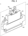
- FIG. 3 and FIG. 4 illustrate a configuration of the head 3.
- FIG. 3 is a perspective view of the head 3
- FIG. 4 is a cross-sectional view of the head 3 taken along a plane S1 in FIG. 3 .
- the head 3 includes multiple discharge modules 310 arranged in one row or a plurality of rows in a housing 300.
- the head 3 includes a supply port 301 and a collection port 302. A liquid pressurized from the outside is supplied to the discharge modules 310 through the supply port 301, and the liquid that is not discharged is drained to the outside through the collection port 302.
- the housing 300 includes a connector 303.
- the discharge module 310 includes a nozzle plate 311 having a nozzle 321 from which a liquid is discharged, a channel 322 communicating with the nozzle 321, and a piezoelectric element 324 that drives a needle-shaped valve to open and close the nozzle 321.
- the pressurized liquid is fed through the channel 322.
- the nozzle plate 311 is joined to the housing 300.
- the channel 322 is shared with the multiple discharge modules 310 in the housing 300.
- the pressurized liquid such as ink is supplied from the supply port 301 to the channel 322 and drained from the collection port 302.
- the discharge module 310 may temporarily stops draining a liquid from the collection port 302 while discharging the liquid to the object 200 from the nozzle 321 to prevent a decrease in a liquid discharge efficiency from the nozzle 321.
- the head 3 is a valve jet type that has multiple nozzles and individually opens and closes the multiple nozzles 321 to discharge the liquid from each of the multiple nozzles 321 to the object 200.
- FIG. 5A is a plan view of a head 3x of piezoelectric drive type
- FIG. 5B is a plan view of the head 3 of valve jet type as viewed in a direction in which the liquid is discharged.
- piezoelectric elements dynamically push out a liquid in a liquid chamber of the head 3x of piezoelectric drive type to discharge the liquid from nozzles 321x formed in a nozzle plate 311x. Since the head 3x uses the piezoelectric elements, many nozzles 321x can be formed in the nozzle plate 311x with high density, and a high-resolution image pattern can be drawn with high quality.
- the head 3 of valve jet type a liquid in the channel 322 (liquid chamber) of the head 3 is kept at high pressure, and the valve of each nozzle 321 is opened and closed to discharge the liquid.
- the head 3 has fewer nozzles per head and discharges a larger amount of liquid from one nozzle than the head 3x of piezoelectric drive type. For this reason, the head 3 can reliably control each of the nozzles as compared with the head 3x of piezoelectric drive type.
- the liquid discharge apparatus 10 includes, but not limited to, the head 3 of valve jet type, and may include the head 3x of piezoelectric drive type.
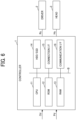
- FIG. 6 is a block diagram illustrating a hardware configuration of the controller 1.
- the controller 1 includes a central processing unit (CPU) 11, a read only memory (ROM) 12, a random access memory (RAM) 13, a hard disk drive (HDD) / solid state drive (SSD) 14, a connection interface (I/F) 15, and a communication I/F 16. These components are electrically connected to each other via a system bus B.
- CPU central processing unit
- ROM read only memory
- RAM random access memory
- HDD hard disk drive
- SSD solid state drive
- I/F connection interface
- the CPU 11 uses the RAM 13 as a work area and executes a program stored in the ROM 12 to control the overall operation of the controller 1.
- the ROM 12 is a non-volatile memory that stores a program for controlling, for example, a recording operation to the CPU 11 and other fixed data.
- the RAM 13 is a volatile memory that temporarily stores various kinds of data.
- the HDD/SSD 14 is a nonvolatile memory that stores the coating area data Pd, the shape data Od of the body of the object 200, and the like.
- the CPU 11 may read the data stored in the HDD/SSD 14 and uses the data to execute the program.
- the connection I/F 15 connects the controller 1 to an external equipment. Examples of the external equipment include the driver 2 and the head 3.
- the communication I/F 16 allows the controller 1 to communicate with the external device such as the external PC.
- FIG. 7 is a block diagram illustrating a functional configuration of the controller 1 according to a first embodiment.
- the controller 1 includes a communication unit 101, an input/output unit 102, a drive command unit 103, a flight angle acquisition unit 104, a discharge amount determination unit 105, a pulse signal generation unit 106, a relative movement trajectory acquisition unit 107, a discharge timing determination unit 108, and a discharge control unit 109.
- the controller 1 implements functions of the communication unit 101 and the input/output unit 102 with the communication I/F 16 and the connection I/F 15, respectively.
- the controller 1 executes a program stored in the ROM 12 with the CPU 11 to implement the functions of the drive command unit 103, the flight angle acquisition unit 104, the discharge amount determination unit 105, the pulse signal generation unit 106, the relative movement trajectory acquisition unit 107, the discharge timing determination unit 108, and the discharge control unit 109.
- the controller 1 may include functional units other than those units described above. Components other than the controller 1 may have some of the above-described functions of the controller 1. Examples of the components other than the controller 1 include the driver 2, the head 3, and the external PC. The controller 1 and the components other than the controller 1 may be dispersed to implement some of the above-described functions of the controller 1. Alternatively, the controller 1 may implement at least a part of the functions to be implemented by the CPU 11 with an electric circuit such as an application specific integrated circuit (ASIC) or a field programmable gate array (FPGA).
- ASIC application specific integrated circuit
- FPGA field programmable gate array
- the communication unit 101 controls communication of signals and data between the controller 1 and the external device such as the external PC.
- the input/output unit 102 controls input and output of signals and data between the controller 1, and the driver 2 and the head 3.
- the drive command unit 103 outputs the drive command Rc to the driver 2 to cause the driver 2 to move the head 3 relative to the object 200.
- the flight angle acquisition unit 104 acquires, by calculation, data of a flight angle ⁇ which is an angle formed between a flight direction of liquid discharged from each of the multiple nozzles 321 and a normal direction of the surface of the object 200. For example, the flight angle acquisition unit 104 acquires data of the normal direction at each position on the surface of the object 200 by calculation based on the shape data Od of the object 200 having a curved surface. Then, the flight angle acquisition unit 104 calculates the angle formed between the flight direction of the liquid and the normal direction of the surface of the object 200, thereby acquiring the data of the flight angle ⁇ .
- the discharge amount determination unit 105 determines an amount of liquid discharged from each of the multiple nozzles 321 (i.e., a liquid discharge amount M) based on the flight angle ⁇ acquired by the flight angle acquisition unit 104, and outputs the liquid discharge amount M to the discharge control unit 109.
- the pulse signal generation unit 106 generates a pulse signal k serving as a reference of a timing at which liquid is discharged from each of the multiple nozzles 321 based on a distance of relative movement between the head 3 and the object 200 by the driver 2 (i.e., a relative movement distance), and outputs the pulse signal k to the discharge timing determination unit 108 and the discharge control unit 109.
- the pulse signal generation unit 106 generates the pulse signal k based on a detection signal output by a detector such as a rotary encoder or an acceleration sensor of the driver 2 in response to the operation of the driver 2.
- the timing at which the pulse signal k is generated may be determined in advance based on an operation simulation of the driver 2.
- the relative movement trajectory acquisition unit 107 acquires data of a trajectory of relative movement between the object 200 and the head 3 (i.e., a relative movement trajectory) by calculation based on the coating area data Pd.
- the discharge timing determination unit 108 determines a liquid discharge timing ⁇ t based on a target distance between the object 200 and each of the multiple nozzles 321, and outputs the liquid discharge timing ⁇ t to the discharge control unit 109. For example, the discharge timing determination unit 108 acquires data of the target distance at each of division points by calculation. The division points divide the relative movement trajectory at discharge intervals between discharge positions, at which a liquid is discharged from each of the multiple nozzles 321, in a direction of relative movement between the multiple nozzles 321 and the object 200 (i.e., a relative movement direction). The discharge timing determination unit 108 determines the liquid discharge timing ⁇ t based on the target distance.
- the discharge control unit 109 outputs the drive signal Hc to the head 3 based on the coating area data Pd, the pulse signal k, the liquid discharge amount M, and the liquid discharge timing ⁇ t to cause the head 3 to discharge the liquid from each of the multiple nozzles 321.
- FIG. 8A is a diagram of the flight direction and the normal direction when the flight angle is 0 degrees, illustrating a method of determining the liquid discharge amount M according to the first embodiment.
- FIG. 8B is a diagram of the flight direction and the normal direction when the flight angle is ⁇ , illustrating the method of determining the liquid discharge amount M according to the first embodiment.
- the liquid is discharged from one nozzle 321 of the head 3 in the direction of gravity.
- the discharged liquid flies in a flight direction 321a, and a normal direction 200a is normal (orthogonal) to the surface of the object 200.
- a flight direction 321a coincides with the direction of gravity.
- the normal direction 200a coincides with the direction of gravity, and the flight angle ⁇ is 0 degrees.
- the normal direction 200a is inclined by the flight angle ⁇ with respect to the direction of gravity.
- the liquid that has landed on the surface of the object 200 may move on the surface of the object 200 under gravity.
- the amount of liquid that moves on the surface of the object 200 increases as the flight angle ⁇ increases. If the liquid moves, the thickness of the film formed on the surface of the object 200 may change, causing coating unevenness.
- the discharge amount determination unit 105 determines the liquid discharge amount M according to the following Equation 1 to correct the film thickness to be changed due to the movement of the liquid.
- M M 0 / cos 2 ⁇
- M 0 represents the liquid discharge amount when the flight angle ⁇ is 0 degrees.
- FIG. 9A is a diagram of the relative movement trajectory divided at discharge intervals, illustrating a method of determining the liquid discharge timing ⁇ t according to the first embodiment.
- FIG. 9B is a diagram of the relative movement trajectory and the target distance, illustrating the method of determining the liquid discharge timing ⁇ t according to the first embodiment.
- FIGS. 9A and 9B illustrate relative movement trajectories 401 and 402, each of which arcs, of two nozzles 321 among the multiple nozzles 321.
- the discharge timing determination unit 108 divides each of the relative movement trajectories 401 and 402 at discharge intervals p. Then, as illustrated in FIG. 9B , when the nozzle 321 is positioned at each of division points 403 that divides the relative movement trajectories 401 and 402, the discharge timing determination unit 108 calculates a target distance d between the nozzle 321 and the object 200, and divides the target distance d by a predetermined speed of the liquid discharged from the nozzle 321 (i.e., a liquid discharge speed Vh). As a result, the discharge timing determination unit 108 can calculate a landing time from when the liquid is discharged from the nozzle 321 to when the liquid lands on the surface of the object 200.
- a predetermined speed of the liquid discharged from the nozzle 321 i.e., a liquid discharge speed Vh
- the discharge timing determination unit 108 subtracts the landing time from the time when the nozzle 321 is positioned at each of the division points 403 to obtain a discharge start time.
- the discharge timing determination unit 108 compares the discharge start time with the pulse signal k to determine the liquid discharge timing ⁇ t. As described above, the controller 1 determines the liquid discharge timing ⁇ t based on the target distance d.
- the pulse signal k is generated each time the nozzle 321 moves a certain distance shorter than the discharge interval p (e.g., half of the discharge interval p).
- the head 3 discharges the liquid once at maximum from the nozzle 321 in response to one pulse signal k. Even when the pulse signal k is generated, the head 3 may not discharge the liquid from the nozzle 321.
- the reason why the pulse signal k is generated each certain distance shorter than the discharge interval p is that the head 3 includes the multiple nozzles 321.
- the pulse signal k is generated based on the distance of movement of the center of the driver 2.
- the controller 1 When the driver 2 moves the relative movement distance L_1 (m) by the discharge intervals p (m), the controller 1 generates the pulse signal k of L_1/p times to achieve a desired discharge interval p.
- the relative movement distance is different for each of the multiple nozzles 321.
- the controller 1 does not achieve the desired discharge interval p with the pulse signal k of L_1/p times for the end nozzle of the multiple nozzles 321.
- the head 3 discharges the liquid from the end nozzle of the multiple nozzles 321 at the average discharge interval (L_2 / L_1) ⁇ p, which is longer than the discharge interval p.
- the controller 1 for example, generates the pulse signal k every time the driver 2 relatively moves a distance of 0.5 times the discharge interval p.
- the controller 1 achieves the desired discharge interval p unless the relative movement distance L_2 is longer than 2 times the relative movement distance L_1.
- FIGS. 10A to 10D are timing charts of a process executed by the controller 1.
- FIG. 10A is a graph of the relative movement distance L of the head 3
- FIG. 10B is a chart of the pulse signal k
- FIG. 10C is a chart of the liquid discharge timing of a first nozzle among the multiple nozzles 321
- FIG. 10D is a chart of the liquid discharge timing of a second nozzle among the multiple nozzles 321.
- the time axes in FIGS. 10A to 10D correspond to each other.
- the pulse signal k is generated at predetermined times t1, t2, t3, t4 and t5 as illustrated in FIG. 10B .
- the controller 1 determines the liquid discharge timing ⁇ t 11 corresponding to the pulse signal k at the time 11, the liquid discharge timing ⁇ t 12 corresponding to the pulse signal k at the time t2, the liquid discharge timing ⁇ t 13 corresponding to the pulse signal k at the time t3, the liquid discharge timing ⁇ t 14 corresponding to the pulse signal k at the time t4, and the liquid discharge timing ⁇ t 15 corresponding to the pulse signal k at the time t5 to generate a timing signal Ts indicating each timing for the first nozzle of the multiple nozzle 321.
- Liquid discharge periods Ts 11 to Ts 14 in FIG. 10C correspond to the liquid discharge amounts corresponding to the timing signal Ts at times t1, t2, t3, t4, and t5, respectively.
- the width of a high state of the timing signal Ts indicates the period during which the liquid is discharged. The longer period of the high state indicates the larger liquid discharge amount. That is, the liquid discharge amount M 11 corresponds to the liquid discharge period Tsu, the liquid discharge amount M 12 corresponds to the liquid discharge period Ts 12 , the liquid discharge amount M 13 corresponds to the liquid discharge period Ts 13 , and the liquid discharge amount M 14 corresponds to the liquid discharge period Ts 14 .
- These liquid discharge amounts M satisfies a relation of M 11 ⁇ M 12 ⁇ M 13 ⁇ M 14 in FIG. 10C .
- the controller 1 determines the liquid discharge timing ⁇ t 21 corresponding to the pulse signal k at the time 11, the liquid discharge timing ⁇ t 22 corresponding to the pulse signal k at the time t2, the liquid discharge timing ⁇ t 23 corresponding to the pulse signal k at the time t3, the liquid discharge timing ⁇ t 24 corresponding to the pulse signal k at the time t4, and the liquid discharge timing ⁇ t 25 corresponding to the pulse signal k at the time t5 to generate a timing signal Ts indicating each timing for the second nozzle of the multiple nozzle 321.
- Liquid discharge periods Ts 21 to Ts 24 in FIG. 10D correspond to the liquid discharge amounts corresponding to the timing signal Ts at times t1, t2, t3, t4, and t5, respectively.
- the liquid discharge amount M 21 corresponds to the liquid discharge period Ts 21
- the liquid discharge amount M 22 corresponds to the liquid discharge period Ts 22
- the liquid discharge amount M 23 corresponds to the liquid discharge period Ts 23
- the liquid discharge amount M 24 corresponds to the liquid discharge period Ts 24 .
- These liquid discharge amounts M satisfies a relation of M 21 ⁇ M 22 ⁇ M 23 ⁇ M 24 in FIG. 10D .
- the controller 1 determines a delay time from one pulse signal k as the liquid discharge timing ⁇ t for each of the multiple nozzles 321. Accordingly, the head 3 discharges the liquid from each of the multiple nozzles 321 after waiting the determined liquid discharge timing ⁇ t from the one pulse signal k.
- FIG. 11 is a flowchart of a process executed by the controller 1.
- the controller 1 starts the process illustrated in FIG. 11 at a timing when the shape data Od and the coating area data Pd are input from the external PC.
- step S111 the controller 1 causes the flight angle acquisition unit 104 to acquire data of the normal direction 200a by calculation based on the shape data Od of the object 200 and to calculate the angle between the flight direction 321a of the liquid and the normal direction 200a, thereby acquiring the flight angle ⁇ .
- step S112 the controller 1 causes the discharge amount determination unit 105 to determine data of the liquid discharge amount M discharged from each of the multiple nozzles 321 by calculation based on the flight angle ⁇ acquired by the flight angle acquisition unit 104, and outputs the data of the liquid discharge amount M to the discharge control unit 109.
- step S113 the controller 1 causes the pulse signal generation unit 106 to generate the pulse signal k serving as the reference of the timing at which a liquid is discharged from each of the multiple nozzles 321 in accordance with the relative movement distance L between the head 3 and the object 200 by the driver 2, and outputs the pulse signal k to the discharge timing determination unit 108 and the discharge control unit 109.
- step S114 the controller 1 causes the relative movement trajectory acquisition unit 107 to acquire data of the relative movement trajectory between the object 200 and the head 3 by calculation based on the coating area data Pd.
- step S115 the controller 1 causes the discharge timing determination unit 108 to acquire data of the target distance d by calculation at each division point 403 that divides the relative movement trajectory by the discharge intervals p for each of the multiple nozzles 321.
- step S116 the controller 1 determines the liquid discharge timing ⁇ t based on the target distance d.
- step S117 the controller 1 causes the discharge control unit 109 to output the drive signal Hc to the head 3 based on the coating area data Pd, the pulse signal k, the liquid discharge amount M, and the liquid discharge timing ⁇ t to cause the head 3 to discharge a liquid from each of the multiple nozzles 321.
- step S118 the controller 1 determines whether to end the process. For example, the controller 1 determines to end the process based on whether the process has been executed based on all of the shape data Od or the coating area data Pd.
- step S118 determines to end the process in step S118 (Yes in step S118), the process ends.
- the controller 1 determines not to end the process in step S118 (No in step S118)
- the controller 1 continues the process from step S111 again.
- the controller 1 causes the head 3 to discharge a liquid based on the shape data Od and the coating area data Pd.
- the liquid discharge apparatus 10 includes the head 3, the driver 2, and the controller 1.
- the controller 1 determines the liquid discharge amount M based on the flight angle ⁇ between the flight direction 321a of the liquid discharged from each of the multiple nozzles 321 and the normal direction 200a of the surface of the object 200 for each of the multiple nozzles 321. For example, the controller 1 determines the liquid discharge amount M at the flight angle ⁇ by Equation 1 described above.
- the controller 1 determines the liquid discharge amount M based on the flight angle ⁇ . Accordingly, for example, the controller 1 can increase the liquid discharge amount M to an area of the surface on which the film having a small film thickness is to be formed due to the movement of the liquid. As a result, the controller 1 can correct the film thickness of the film to be formed on the surface of the object 200, and thus the liquid discharge apparatus 10 that forms a film having good uniformity can be provided.
- the controller 1 determines the liquid discharge timing ⁇ t based on the target distance d. For example, the controller 1 determines the liquid discharge timing ⁇ t based on the target distance d at each division point that divides the relative movement trajectory between the nozzle 321 and the object 200 by the discharge intervals p.
- the target distance d is different for each of the multiple nozzles 321. Since the head 3 and the object 200 move relative to each other, the landing position of the liquid on the surface of the object 200 deviates from a desired position due to the difference in the target distance d.
- the controller 1 determines the liquid discharge timing ⁇ t to change the landing position for each of the multiple nozzles 321 based on the target distance d, thereby reducing the deviation of the landing position described above. Accordingly, the liquid can be landed at a desired position on the surface of the object 200, and a desired film having good uniformity can be formed on the surface of the object 200.
- the head 3 individually opens and closes multiple nozzles 321 to discharge a liquid from each of the multiple nozzles 321 to the object 200.
- the head 3 has fewer nozzles per head and can discharge a larger amount of liquid from one nozzle than the head of piezoelectric drive type. Accordingly, the controller 1 can individually control the multiple nozzles 321 to efficiently form a film on the object 200.
- the liquid discharge apparatus 10 is described. However, the same effects as that of the liquid discharge apparatus 10 apply to a control apparatus including the function of the controller 1 and a liquid discharge system including the control apparatus, the driver 2, and a liquid discharge apparatus including the head 3.
- a controller 1a according to a second embodiment is described below.
- the same components as those of the first embodiment are denoted by the same reference numerals, and redundant description thereof is appropriately omitted.
- FIG. 12 is a block diagram illustrating an example of the functional configuration of the controller 1a.
- the controller 1a further includes a head angle acquisition unit 110, a storage unit 111, a discharge amount determination unit 105a, a relative movement speed acquisition unit 112, and a discharge timing determination unit 108a.
- the controller 1a implements a function of the storage unit 111 with the HDD/SSD 14.
- the controller 1a executes a program stored in the ROM 12 with the CPU 11 to implement functions of the head angle acquisition unit 110, the discharge amount determination unit 105a, the relative movement speed acquisition unit 112, and the discharge timing determination unit 108a.
- components other than the controller 1a may have some of the above-described functions of the controller 1a, or the controller 1a and the components other than the controller 1 may be dispersed to implement some of the above-described functions of the controller 1a.
- the controller 1a may implement at least a part of the functions to be implemented by the CPU 11 with an electric circuit such the ASIC or the FPGA.
- the head angle acquisition unit 110 acquires, by calculation, data of a head angle ⁇ which is an angle formed between the flight direction 321a of the liquid discharged from the nozzle 321 to be changed by the driver 2 and the direction of gravity. For example, the head angle acquisition unit 110 acquires data of the head angle ⁇ based on a detection signal output from the detector such as the rotary encoder of the driver 2.
- the storage unit 111 stores correspondence data 113 that is information indicating a correspondence between the flight angle ⁇ , the target distance d, and the head angle ⁇ or information related to the correspondence.
- the correspondence data 113 can be determined in advance by a preliminary experiment or the like.
- the discharge amount determination unit 105a determines the liquid discharge amount M based on the flight angle ⁇ , the target distance d of each of the multiple nozzles 321, and the head angle ⁇ , and outputs the liquid discharge amount M to the discharge control unit 109. For example, the discharge amount determination unit 105a determines the liquid discharge amount M with reference to the correspondence data 113 stored in the storage unit 111.
- the relative movement speed acquisition unit 112 acquires data of a speed of relative movement between the head 3 and the object 200 (i.e., a relative movement speed v) by calculation.
- the relative movement speed acquisition unit 112 acquires the data of the relative movement speed v based on a detection signal output from the detector such as the rotary encoder of the driver 2.
- the discharge timing determination unit 108a determines the liquid discharge timing ⁇ t based on the target distance d and the relative movement speed v between the head 3 and the object 200, and outputs the liquid discharge timing ⁇ t to the discharge control unit 109.
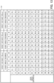
- FIG. 13 is a table of the correspondence data 113, illustrating a method of determining the liquid discharge amount M according to the second embodiment.
- the liquid discharge amount M for each head angle ⁇ is illustrated as a row
- the liquid discharge amount for each of the target distance d and the flight angle ⁇ is illustrated as a column.
- A1_1, A2_1, ..., C4_13, and C5_13 each represent the liquid discharge amount M.
- the discharge amount determination unit 105a determines the liquid discharge amount M with reference to the correspondence data 113 based on the input head angle ⁇ , target distance d, and flight angle ⁇ .
- the liquid discharge amount M can be determined more precisely with the high-resolution of each of the head angle ⁇ , the target distance d, and the flight angle ⁇ , but on the other hand, the data amount of the correspondence data 113 increases.
- the discharge amount determination unit 105a preferably interpolates the liquid discharge amount M beyond the resolution of each of the head angle ⁇ , the target distance d, and the flight angle ⁇ by interpolation calculation or the like. Examples of the calculation is described below.
- the liquid discharge amount M is acquired when the target distance d is 13 (mm), the flight angle ⁇ is 35 (degrees), and the head angle ⁇ is 50 (degrees) as follows.
- the discharge amount determination unit 105a calculates the liquid discharge amount M 11 when the target distance d is 10 (mm), the flight angle ⁇ is 30 (degrees), and the head angle ⁇ is 50 (degrees) by the following equation.
- M 11 1 ⁇ 60 ⁇ 50 / 60 ⁇ 45 ⁇ A 3 _ 4 + 60 ⁇ 50 / 60 ⁇ 45 ⁇ A 3 _ 5
- the discharge amount determination unit 105a calculates the liquid discharge amount M 12 when the target distance d is 10 (mm), the flight angle ⁇ is 45 (degrees), and the head angle ⁇ is 50 (degrees) by the following equation.
- M 12 1 ⁇ 60 ⁇ 50 / 60 ⁇ 45 ⁇ A 4 _ 4 + 60 ⁇ 50 / 60 ⁇ 45 ⁇ A 4 _ 5
- the discharge amount determination unit 105a calculates the liquid discharge amount M 13 when the target distance d is 20 (mm), the flight angle ⁇ is 30 (degrees), and the head angle ⁇ is 50 (degrees) by the following equation.
- M 13 1 ⁇ 60 ⁇ 50 / 60 ⁇ 45 ⁇ B 3 _ 4 + 60 ⁇ 50 / 60 ⁇ 45 ⁇ B 3 _ 5
- the discharge amount determination unit 105a calculates the liquid discharge amount M 14 when the target distance d is 20 (mm), the flight angle ⁇ is 45 (degrees), and the head angle ⁇ is 50 (degrees) by the following equation.
- M 14 1 ⁇ 60 ⁇ 50 / 60 ⁇ 45 ⁇ B 4 _ 4 + 60 ⁇ 50 / 60 ⁇ 45 ⁇ B 4 _ 5
- the discharge amount determination unit 105a calculates the liquid discharge amount M 21 when the target distance d is 10 (mm), the flight angle ⁇ is 35 (degrees), and the head angle ⁇ is 50 (degrees) by the following equation.
- M 21 1 ⁇ 35 ⁇ 30 / 45 ⁇ 30 ⁇ M 11 + 35 ⁇ 30 / 45 ⁇ 30 ⁇ M 12
- the discharge amount determination unit 105a calculates the liquid discharge amount M 22 when the target distance d is 20 (mm), the flight angle ⁇ is 35 (degrees), and the head angle ⁇ is 50 (degrees) by the following equation.
- M 22 1 ⁇ 35 ⁇ 30 / 45 ⁇ 30 ⁇ M 13 + 35 ⁇ 30 / 45 ⁇ 30 ⁇ M 14
- the discharge amount determination unit 105a calculates the liquid discharge amount M when the target distance d is 13 (mm), the flight angle ⁇ is 35 (degrees), and the head angle ⁇ is 50 (degrees) by the following equation.
- M 1 ⁇ 13 ⁇ 10 / 20 ⁇ 10 ⁇ M 21 + 13 ⁇ 10 / 20 ⁇ 10 ⁇ M 22
- the discharge amount determination unit 105a determines the liquid discharge amount M beyond the resolution of each of the head angle ⁇ , the target distance d, and the flight angle ⁇ by the interpolation calculation.
- FIGS. 14A to 14D are diagrams of the relative movement trajectory, illustrating a method of determining the liquid discharge timing ⁇ t according to the second embodiment.
- FIG. 14A is a diagram of a relative movement start position and a relative movement end position on the relative movement trajectory.
- FIG. 14B is a diagram of a start landing position and a desired next landing position on the object.
- FIG. 14C is a diagram of a position of a desired nozzle on the relative movement trajectory.
- FIG. 14D is a diagram of landing positions on the object.
- the discharge timing determination unit 108a determines the liquid discharge timing ⁇ t based on the target distance d and the relative movement speed v.
- a velocity vector of a liquid flying toward the object 200 is represented by a composite vector of the velocity vector of the discharged liquid and the velocity vector of the relative movement between the head 3 and the object 200.
- the discharge timing determination unit 108a can determine the liquid discharge timing ⁇ t based on the head angle ⁇ in addition to the target distance d and the relative movement speed v, thereby reducing the deviation of the landing position due to gravity.
- the controller 1 determines a relative movement start position 404 and a relative movement end position 405 on the relative movement trajectory 401 of the nozzle 321.
- the controller calculates a start landing position 406 on the surface of the object 200, onto which the liquid discharged from the relative movement start position 404 lands.
- the controller 1 calculates a desired next landing position 407 shifted by the discharge interval p in the relative movement direction.
- the controller 1 specifies a desired nozzle 408 that can discharge the liquid onto the desired next landing position 407, and calculates the landing position of the liquid discharged from the desired nozzle 408. In this case, the controller 1 calculates the landing position based on a flight trajectory of the liquid in consideration of the relative movement speed v combined with the liquid discharge speed Vh. Thus, the controller 1 compares the time at the landing position and the pulse signal k to determine the liquid discharge timing ⁇ t.
- FIG. 15 is a flowchart of a process executed by the controller 1a.
- the controller 1a starts the process illustrated in FIG. 15 at a timing when the shape data Od and the coating area data Pd are input from the external PC. Note that redundant description of steps that are the same steps as in the process illustrated in FIG. 11 is omitted as appropriate.
- step S151 is the same as the step S111 in FIG. 11 .
- step S152 the controller 1a causes the head angle acquisition unit 110 to acquire, by calculation, data of the head angle ⁇ between the flight direction 321a of the liquid discharged from the nozzle 321 to be changed by the driver 2 and the direction of gravity.
- step S153 the controller 1a causes the discharge amount determination unit 105a to determine the liquid discharge amount M based on the flight angle ⁇ , the target distance d of each of the multiple nozzles 321, and the head angle ⁇ with reference to the correspondence data 113.
- step S154 to S156 is the same as the steps S113 to S115 in FIG. 11 .
- step S157 the controller 1a causes the relative movement speed acquisition unit 112 to acquire data of a relative movement speed v between the head 3 and the object 200 by calculation.
- step S158 the controller 1a causes the discharge timing determination unit 108a to determine the liquid discharge timing ⁇ t based on the target distance d and the relative movement speed v between the head 3 and the object 200.
- the steps S159 and S160 is the same as the steps S117 and S118 in FIG. 11 .
- the controller 1a causes the head 3 to discharge a liquid based on the shape data Od and the coating area data Pd.
- the driver 2 changes the head angle ⁇ between the flight direction 321a of the liquid discharged from each of the multiple nozzles 321 and the direction of gravity, and the controller 1a determines the liquid discharge amount M based on the flight angle ⁇ , the target distance d of each of the multiple nozzles 321, and the head angle ⁇ for each of the multiple nozzles 321. Accordingly, even when the head angle ⁇ of the head 3 is changed by the driver 2, the controller 1 can accurately determine the liquid discharge amount M.
- the controller determines the liquid discharge timing ⁇ t based on the target distance d and the relative movement speed v between the head 3 and the object 200.
- the controller 1 can accurately determine the liquid discharge timing ⁇ t.
- examples of the liquid discharged from the head 3 include a solution, a suspension, or an emulsion that contains, for example, a solvent, such as water or an organic solvent, a colorant, such as dye or pigment, a functional material, such as a polymerizable compound, a resin, or a surfactant, a biocompatible material, such as DNA, amino acid, protein, or calcium, or an edible material, such as a natural colorant.
- a solvent such as water or an organic solvent
- a colorant such as dye or pigment
- a functional material such as a polymerizable compound, a resin, or a surfactant
- a biocompatible material such as DNA, amino acid, protein, or calcium
- an edible material such as a natural colorant.
- the object 200 represents a material onto which liquid is adhered and fixed, a material into which liquid is adhered to permeate, or the like.
- Specific examples of the "material onto which liquid can adhere” include, but are not limited to, a body of a vehicle, a construction material, a recording medium such as a paper sheet, recording paper, a recording sheet of paper, a film, or cloth, an electronic component such as an electronic substrate or a piezoelectric element, and a medium such as layered powder, an organ model, or a testing cell.
- the "material onto which liquid can adhere” includes any material to which liquid adheres, unless particularly limited.
- Embodiments also include a liquid discharge method.
- a liquid discharge method includes discharging a liquid from each of multiple nozzles of a head to an object in a flight direction to form a film on a surface of the object, moving at least one of the head and the object relative to other of the head and the object, determining an amount of the liquid discharged from each of the multiple nozzles based on a flight angle between the flight direction and a normal direction of the surface of the object for each of the multiple nozzles, and discharging the liquid from each of the multiple nozzles for the amount of the liquid determined for each of the multiple nozzles.
- Such a liquid discharge method can provide operational effects equivalent to those of the above-described liquid discharge apparatus.
- Embodiments also include a carrier medium carrying computer-readable program instructions and a computer-readable program product.
- a carrier medium carrying computer readable code for controlling a computer system to carry out a method including discharging a liquid from each of multiple nozzles of a head to an object in a flight direction to form a film on a surface of the object, moving at least one of the head and the object relative to other of the head and the object, determining an amount of the liquid discharged from each of the multiple nozzles based on a flight angle between the flight direction and a normal direction of the surface of the object for each of the multiple nozzles, and discharging the liquid from each of the multiple nozzles for the amount of the liquid determined for each of the multiple nozzles.
- a carrier medium or a computer-readable program product including such program code can provide operational effects equivalent to those of the above-described liquid discharge apparatus. Any one of the above-described operations may be performed in various other ways, for example, in an order different from the one described above.
- the present invention can be implemented in any convenient form, for example using dedicated hardware, or a mixture of dedicated hardware and software.
- the present invention may be implemented as computer software implemented by one or more networked processing apparatuses.
- the processing apparatuses include any suitably programmed apparatuses such as a general purpose computer, a personal digital assistant, a Wireless Application Protocol (WAP) or third-generation (3G)-compliant mobile telephone, and so on. Since the present invention can be implemented as software, each and every aspect of the present invention thus encompasses computer software implementable on a programmable device.
- the computer software can be provided to the programmable device using any conventional carrier medium (carrier means).
- the carrier medium includes a transient carrier medium such as an electrical, optical, microwave, acoustic or radio frequency signal carrying the computer code.
- transient medium is a Transmission Control Protocol/Internet Protocol (TCP/IP) signal carrying computer code over an IP network, such as the Internet.
- the carrier medium may also include a storage medium for storing processor readable code such as a floppy disk, a hard disk, a compact disc read-only memory (CD-ROM), a magnetic tape device, or a solid state memory device.
Landscapes
- Engineering & Computer Science (AREA)
- Coating Apparatus (AREA)
- Robotics (AREA)
- Manufacturing & Machinery (AREA)
- Application Of Or Painting With Fluid Materials (AREA)
Abstract
Description
- Embodiments of the present disclosure relate to a liquid discharge apparatus, a liquid discharge method, and a carrier medium carrying computer readable code.
- In the related art, a liquid discharge apparatus forms a film on a surface of an object with a liquid. Such a liquid discharge apparatus is used for coating the surface of the object. For example,
Japanese Unexamined Patent Application Publication No. 2021-088109 Japanese Unexamined Patent Application Publication No. 2021-088109 - An object of the present disclosure is to provide a liquid discharge apparatus that forms a film having good uniformity.
- Embodiments of the present disclosure describe an improved liquid discharge apparatus that includes a head, a driver, and circuitry. The head has multiple nozzles and discharges a liquid from each of multiple nozzles to an object in a flight direction to form a film on a surface of the object. The driver moves at least one of the head and the object relative to other of the head and the object. The circuitry determines an amount of the liquid discharged from each of the multiple nozzles based on a flight angle between the flight direction and a normal direction of the surface of the object for each of the multiple nozzles and causes the head to discharge the liquid from each of the multiple nozzles for the amount of the liquid determined for each of the multiple nozzles.
- According to other embodiments of the present disclosure, there are provided a liquid discharge method and a carrier medium carrying computer readable code for controlling a computer system to carry out the liquid discharge method. The method includes discharging a liquid from each of multiple nozzles of a head to an object in a flight direction to form a film on a surface of the object, moving at least one of the head and the object relative to other of the head and the object, determining an amount of the liquid discharged from each of the multiple nozzles based on a flight angle between the flight direction and a normal direction of the surface of the object for each of the multiple nozzles, and discharging the liquid from each of the multiple nozzles for the amount of the liquid determined for each of the multiple nozzles.
- As a result, according to the present disclosure, the liquid discharge apparatus that forms a film having good uniformity can be provided.
- A more complete appreciation of the disclosure and many of the attendant advantages and features thereof can be readily obtained and understood from the following detailed description with reference to the accompanying drawings, wherein:
-
FIG. 1 is a schematic view of a liquid discharge apparatus according to embodiments of the present disclosure; -
FIG. 2 is a block diagram of the liquid discharge apparatus according to embodiments of the present disclosure; -
FIG. 3 is a perspective view of a head of the liquid discharge apparatus according to embodiments of the present disclosure; -
FIG. 4 is a cross-sectional view of the head taken along a plane S1 inFIG. 3 ; -
FIG. 5A is a plan view of the head of piezoelectric drive type; -
FIG. 5B is a plan view of the head of valve jet type; -
FIG. 6 is a block diagram illustrating a hardware configuration of a controller of the liquid discharge apparatus according to embodiments of the present disclosure; -
FIG. 7 is a block diagram illustrating a functional configuration of the controller according to a first embodiment; -
FIG. 8A is a diagram of a flight direction and a normal direction when a flight angle is 0 degrees, illustrating a method of determining a liquid discharge amount according to the first embodiment; -
FIG. 8B is a diagram of the flight direction and the normal direction when the flight angle is θ, illustrating the method of determining the liquid discharge amount according to the first embodiment; -
FIG. 9A is a diagram of a relative movement trajectory divided at discharge intervals, illustrating a method of determining a liquid discharge timing according to the first embodiment; -
FIG. 9B is a diagram of the relative movement trajectory and a target distance, illustrating the method of determining the liquid discharge timing according to the first embodiment; -
FIG. 10A is a timing chart illustrating a relative movement distance in a process executed by the controller according to the first embodiment; -
FIG. 10B is a timing chart illustrating a pulse signal in the process executed by the controller according to the first embodiment; -
FIG. 10C is a timing chart illustrating a liquid discharge timing of one nozzle in the process executed by the controller according to the first embodiment; -
FIG. 10D is a timing chart illustrating a liquid discharge timing of another nozzle in the process executed by the controller according to the first embodiment; -
FIG. 11 is a flowchart illustrating an example of the process executed by the controller according to the first embodiment; -
FIG. 12 is a block diagram illustrating a functional configuration of the controller according to a second embodiment; -
FIG. 13 is a table illustrating a method of determining the liquid discharge amount according to the second embodiment; -
FIG. 14A is a diagram of a relative movement start position and a relative movement end position on the relative movement trajectory, illustrating a method of determining a liquid discharge timing according to the second embodiment; -
FIG. 14B is a diagram of a start landing position and a desired next landing position on the object, illustrating the method of determining the liquid discharge timing according to the second embodiment; -
FIG. 14C is a diagram of a position of a desired nozzle on the relative movement trajectory, illustrating the method of determining the liquid discharge timing according to the second embodiment; -
FIG. 14D is a diagram of landing positions on the object and positions of the corresponding nozzle, illustrating the method of determining the liquid discharge timing according to the second embodiment; and -
FIG. 15 is a flowchart illustrating an example of the process executed by the controller according to the second embodiment. - The accompanying drawings are intended to depict embodiments of the present invention and should not be interpreted to limit the scope thereof. The accompanying drawings are not to be considered as drawn to scale unless explicitly noted. Also, identical or similar reference numerals designate identical or similar components throughout the several views.
- In describing embodiments illustrated in the drawings, specific terminology is employed for the sake of clarity. However, the disclosure of this specification is not intended to be limited to the specific terminology so selected and it is to be understood that each specific element includes all technical equivalents that have a similar function, operate in a similar manner, and achieve a similar result.
- Referring now to the drawings, embodiments of the present disclosure are described below. As used herein, the singular forms "a," "an," and "the" are intended to include the plural forms as well, unless the context clearly indicates otherwise.
- A liquid discharge apparatus according to an embodiment of the present disclosure is described with reference to the drawings. However, embodiments described below are some examples of the liquid discharge apparatus for embodying the technical idea of the present disclosure, and embodiments of the present disclosure are not limited to the embodiments described below. The dimensions, materials, and shapes of components, relative arrangements thereof, and the like described below are not intended to limit the scope of the present disclosure thereto unless otherwise specified and are only examples for explanation. The size, positional relation, and the like of components illustrated in the drawings may be exaggerated for clarity of description. In the following description, the same names and the same reference codes represent the same or equivalent components, and a detailed description thereof is omitted as appropriate.
- An overall configuration of a
liquid discharge apparatus 10 is described with reference toFIGS. 1 and 2. FIG. 1 is a Schematic view of theliquid discharge apparatus 10 according to the present embodiment, andFIG. 2 is a block diagram of theliquid discharge apparatus 10 according to the present embodiment. - As illustrated in
FIGS. 1 and 2 , theliquid discharge apparatus 10 includes acontroller 1, adriver 2, and ahead 3. Theliquid discharge apparatus 10 is a coating apparatus that applies a liquid discharged from thehead 3 by an ink jet method to a surface of anobject 200 to coat the surface of theobject 200. Examples of the liquid include paint, ink, or the like. - The
object 200 has an impermeable surface, such as a body of a car, a truck, or an aircraft. Here, the impermeable surface has a property of preventing a liquid applied to the surface of theobject 200 from permeating into the interior. However, the surface of theobject 200 is not limited to the impermeable surface and may be a permeable surface. In the present embodiment, theobject 200 has a curved surface having a curvature but may has a flat surface. - Examples of the
controller 1 include a personal computer (PC) or the like, which serves as a control apparatus that causes thehead 3 to discharge a liquid. Thecontroller 1 is connected to thedriver 2 and thehead 3 so as to communicate with each other via a wire or wirelessly. Thecontroller 1 outputs a drive command Rc to thedriver 2 so as to cause thedriver 2 to move thehead 3 and outputs a drive signal Hc to thehead 3 so as to cause thehead 3 to discharge a liquid based on shape data Od and coating area data Pd. The shape data Od is transmitted from an external device such as an external PC and indicates a shape of theobject 200. The coating area data Pd indicates an area to be coated on the surface of theobject 200. - Examples of the
driver 2 includes a multi-axis drivable robot arm that relatively moves thehead 3 and theobject 200, in other words, moves at least one of thehead 3 and theobject 200 relative to the other of thehead 3 and theobject 200. Thedriver 2 holds thehead 3 and moves thehead 3 to a desired position in a three-dimensional space. Theliquid discharge apparatus 10 causes thehead 3 to discharge a liquid to a desired position on theobject 200 while driving thedriver 2. Thedriver 2 is not limited to the robot arm and may include a stage that is linearly movable in three axial directions. Thedriver 2 may move theobject 200 without moving thehead 3, or may move both thehead 3 and theobject 200. -
FIG. 3 andFIG. 4 illustrate a configuration of thehead 3.FIG. 3 is a perspective view of thehead 3, andFIG. 4 is a cross-sectional view of thehead 3 taken along a plane S1 inFIG. 3 . - The
head 3 includesmultiple discharge modules 310 arranged in one row or a plurality of rows in ahousing 300. Thehead 3 includes asupply port 301 and acollection port 302. A liquid pressurized from the outside is supplied to thedischarge modules 310 through thesupply port 301, and the liquid that is not discharged is drained to the outside through thecollection port 302. Thehousing 300 includes aconnector 303. - The
discharge module 310 includes anozzle plate 311 having anozzle 321 from which a liquid is discharged, achannel 322 communicating with thenozzle 321, and apiezoelectric element 324 that drives a needle-shaped valve to open and close thenozzle 321. The pressurized liquid is fed through thechannel 322. - The
nozzle plate 311 is joined to thehousing 300. Thechannel 322 is shared with themultiple discharge modules 310 in thehousing 300. The pressurized liquid such as ink is supplied from thesupply port 301 to thechannel 322 and drained from thecollection port 302. Thedischarge module 310 may temporarily stops draining a liquid from thecollection port 302 while discharging the liquid to theobject 200 from thenozzle 321 to prevent a decrease in a liquid discharge efficiency from thenozzle 321. - The
head 3 is a valve jet type that has multiple nozzles and individually opens and closes themultiple nozzles 321 to discharge the liquid from each of themultiple nozzles 321 to theobject 200.FIG. 5A is a plan view of ahead 3x of piezoelectric drive type, andFIG. 5B is a plan view of thehead 3 of valve jet type as viewed in a direction in which the liquid is discharged. - In the
head 3x of piezoelectric drive type, piezoelectric elements dynamically push out a liquid in a liquid chamber of thehead 3x of piezoelectric drive type to discharge the liquid fromnozzles 321x formed in anozzle plate 311x. Since thehead 3x uses the piezoelectric elements,many nozzles 321x can be formed in thenozzle plate 311x with high density, and a high-resolution image pattern can be drawn with high quality. - In the
head 3 of valve jet type, a liquid in the channel 322 (liquid chamber) of thehead 3 is kept at high pressure, and the valve of eachnozzle 321 is opened and closed to discharge the liquid. Thehead 3 has fewer nozzles per head and discharges a larger amount of liquid from one nozzle than thehead 3x of piezoelectric drive type. For this reason, thehead 3 can reliably control each of the nozzles as compared with thehead 3x of piezoelectric drive type. In the present embodiment, theliquid discharge apparatus 10 includes, but not limited to, thehead 3 of valve jet type, and may include thehead 3x of piezoelectric drive type. -
FIG. 6 is a block diagram illustrating a hardware configuration of thecontroller 1. Thecontroller 1 includes a central processing unit (CPU) 11, a read only memory (ROM) 12, a random access memory (RAM) 13, a hard disk drive (HDD) / solid state drive (SSD) 14, a connection interface (I/F) 15, and a communication I/F 16. These components are electrically connected to each other via a system bus B. - The
CPU 11 uses theRAM 13 as a work area and executes a program stored in theROM 12 to control the overall operation of thecontroller 1. TheROM 12 is a non-volatile memory that stores a program for controlling, for example, a recording operation to theCPU 11 and other fixed data. TheRAM 13 is a volatile memory that temporarily stores various kinds of data. - The HDD/SSD 14 is a nonvolatile memory that stores the coating area data Pd, the shape data Od of the body of the
object 200, and the like. TheCPU 11 may read the data stored in the HDD/SSD 14 and uses the data to execute the program. The connection I/F 15 connects thecontroller 1 to an external equipment. Examples of the external equipment include thedriver 2 and thehead 3. The communication I/F 16 allows thecontroller 1 to communicate with the external device such as the external PC. -
FIG. 7 is a block diagram illustrating a functional configuration of thecontroller 1 according to a first embodiment. Thecontroller 1 includes acommunication unit 101, an input/output unit 102, adrive command unit 103, a flightangle acquisition unit 104, a dischargeamount determination unit 105, a pulsesignal generation unit 106, a relative movementtrajectory acquisition unit 107, a dischargetiming determination unit 108, and adischarge control unit 109. - The
controller 1 implements functions of thecommunication unit 101 and the input/output unit 102 with the communication I/F 16 and the connection I/F 15, respectively. Thecontroller 1 executes a program stored in theROM 12 with theCPU 11 to implement the functions of thedrive command unit 103, the flightangle acquisition unit 104, the dischargeamount determination unit 105, the pulsesignal generation unit 106, the relative movementtrajectory acquisition unit 107, the dischargetiming determination unit 108, and thedischarge control unit 109. - Note that the
controller 1 may include functional units other than those units described above. Components other than thecontroller 1 may have some of the above-described functions of thecontroller 1. Examples of the components other than thecontroller 1 include thedriver 2, thehead 3, and the external PC. Thecontroller 1 and the components other than thecontroller 1 may be dispersed to implement some of the above-described functions of thecontroller 1. Alternatively, thecontroller 1 may implement at least a part of the functions to be implemented by theCPU 11 with an electric circuit such as an application specific integrated circuit (ASIC) or a field programmable gate array (FPGA). - The
communication unit 101 controls communication of signals and data between thecontroller 1 and the external device such as the external PC. The input/output unit 102 controls input and output of signals and data between thecontroller 1, and thedriver 2 and thehead 3. Thedrive command unit 103 outputs the drive command Rc to thedriver 2 to cause thedriver 2 to move thehead 3 relative to theobject 200. - The flight
angle acquisition unit 104 acquires, by calculation, data of a flight angle θ which is an angle formed between a flight direction of liquid discharged from each of themultiple nozzles 321 and a normal direction of the surface of theobject 200. For example, the flightangle acquisition unit 104 acquires data of the normal direction at each position on the surface of theobject 200 by calculation based on the shape data Od of theobject 200 having a curved surface. Then, the flightangle acquisition unit 104 calculates the angle formed between the flight direction of the liquid and the normal direction of the surface of theobject 200, thereby acquiring the data of the flight angle θ. - The discharge
amount determination unit 105 determines an amount of liquid discharged from each of the multiple nozzles 321 (i.e., a liquid discharge amount M) based on the flight angle θ acquired by the flightangle acquisition unit 104, and outputs the liquid discharge amount M to thedischarge control unit 109. - The pulse
signal generation unit 106 generates a pulse signal k serving as a reference of a timing at which liquid is discharged from each of themultiple nozzles 321 based on a distance of relative movement between thehead 3 and theobject 200 by the driver 2 (i.e., a relative movement distance), and outputs the pulse signal k to the dischargetiming determination unit 108 and thedischarge control unit 109. For example, the pulsesignal generation unit 106 generates the pulse signal k based on a detection signal output by a detector such as a rotary encoder or an acceleration sensor of thedriver 2 in response to the operation of thedriver 2. The timing at which the pulse signal k is generated may be determined in advance based on an operation simulation of thedriver 2. - The relative movement
trajectory acquisition unit 107 acquires data of a trajectory of relative movement between theobject 200 and the head 3 (i.e., a relative movement trajectory) by calculation based on the coating area data Pd. - The discharge
timing determination unit 108 determines a liquid discharge timing Δt based on a target distance between theobject 200 and each of themultiple nozzles 321, and outputs the liquid discharge timing Δt to thedischarge control unit 109. For example, the dischargetiming determination unit 108 acquires data of the target distance at each of division points by calculation. The division points divide the relative movement trajectory at discharge intervals between discharge positions, at which a liquid is discharged from each of themultiple nozzles 321, in a direction of relative movement between themultiple nozzles 321 and the object 200 (i.e., a relative movement direction). The dischargetiming determination unit 108 determines the liquid discharge timing Δt based on the target distance. - The
discharge control unit 109 outputs the drive signal Hc to thehead 3 based on the coating area data Pd, the pulse signal k, the liquid discharge amount M, and the liquid discharge timing Δt to cause thehead 3 to discharge the liquid from each of themultiple nozzles 321. -
FIG. 8A is a diagram of the flight direction and the normal direction when the flight angle is 0 degrees, illustrating a method of determining the liquid discharge amount M according to the first embodiment.FIG. 8B is a diagram of the flight direction and the normal direction when the flight angle is θ, illustrating the method of determining the liquid discharge amount M according to the first embodiment. InFIGS. 8A and 8B , the liquid is discharged from onenozzle 321 of thehead 3 in the direction of gravity. - The discharged liquid flies in a
flight direction 321a, and anormal direction 200a is normal (orthogonal) to the surface of theobject 200. In the examples illustrated inFIGS. 8A and 8B , theflight direction 321a coincides with the direction of gravity. - In
FIG. 8A , thenormal direction 200a coincides with the direction of gravity, and the flight angle θ is 0 degrees. On the other hand, inFIG. 8B , thenormal direction 200a is inclined by the flight angle θ with respect to the direction of gravity. When thenormal direction 200a is inclined, the liquid that has landed on the surface of theobject 200 may move on the surface of theobject 200 under gravity. The amount of liquid that moves on the surface of theobject 200 increases as the flight angle θ increases. If the liquid moves, the thickness of the film formed on the surface of theobject 200 may change, causing coating unevenness. In the present embodiment, the dischargeamount determination unit 105 determines the liquid discharge amount M according to the followingEquation 1 to correct the film thickness to be changed due to the movement of the liquid.
-
FIG. 9A is a diagram of the relative movement trajectory divided at discharge intervals, illustrating a method of determining the liquid discharge timing Δt according to the first embodiment.FIG. 9B is a diagram of the relative movement trajectory and the target distance, illustrating the method of determining the liquid discharge timing Δt according to the first embodiment.FIGS. 9A and 9B illustraterelative movement trajectories nozzles 321 among themultiple nozzles 321. - As illustrated in
FIG. 9A , the dischargetiming determination unit 108 divides each of therelative movement trajectories FIG. 9B , when thenozzle 321 is positioned at each of division points 403 that divides therelative movement trajectories timing determination unit 108 calculates a target distance d between thenozzle 321 and theobject 200, and divides the target distance d by a predetermined speed of the liquid discharged from the nozzle 321 (i.e., a liquid discharge speed Vh). As a result, the dischargetiming determination unit 108 can calculate a landing time from when the liquid is discharged from thenozzle 321 to when the liquid lands on the surface of theobject 200. - Next, the discharge
timing determination unit 108 subtracts the landing time from the time when thenozzle 321 is positioned at each of the division points 403 to obtain a discharge start time. The dischargetiming determination unit 108 compares the discharge start time with the pulse signal k to determine the liquid discharge timing Δt. As described above, thecontroller 1 determines the liquid discharge timing Δt based on the target distance d. - The pulse signal k is generated each time the
nozzle 321 moves a certain distance shorter than the discharge interval p (e.g., half of the discharge interval p). Thehead 3 discharges the liquid once at maximum from thenozzle 321 in response to one pulse signal k. Even when the pulse signal k is generated, thehead 3 may not discharge the liquid from thenozzle 321. - The reason why the pulse signal k is generated each certain distance shorter than the discharge interval p is that the
head 3 includes themultiple nozzles 321. The pulse signal k is generated based on the distance of movement of the center of thedriver 2. When thedriver 2 moves the relative movement distance L_1 (m) by the discharge intervals p (m), thecontroller 1 generates the pulse signal k of L_1/p times to achieve a desired discharge interval p. - When the
head 3 includes themultiple nozzles 321, the relative movement distance is different for each of themultiple nozzles 321. For example, an end nozzle at the end of themultiple nozzles 321, which is away from the center of themultiple nozzles 321, moves the relative movement distance L_2 (m) longer than the relative movement distance L_1 due to the difference of turning radius between the end and center of themultiple nozzles 321 when thehead 3 moves so as to draw a curve. As a result, thecontroller 1 does not achieve the desired discharge interval p with the pulse signal k of L_1/p times for the end nozzle of themultiple nozzles 321. For example, thehead 3 discharges the liquid from the end nozzle of themultiple nozzles 321 at the average discharge interval (L_2 / L_1) × p, which is longer than the discharge interval p. In such a case, thecontroller 1, for example, generates the pulse signal k every time thedriver 2 relatively moves a distance of 0.5 times the discharge interval p. As a result, thecontroller 1 achieves the desired discharge interval p unless the relative movement distance L_2 is longer than 2 times the relative movement distance L_1. -
FIGS. 10A to 10D are timing charts of a process executed by thecontroller 1.FIG. 10A is a graph of the relative movement distance L of thehead 3,FIG. 10B is a chart of the pulse signal k,FIG. 10C is a chart of the liquid discharge timing of a first nozzle among themultiple nozzles 321, andFIG. 10D is a chart of the liquid discharge timing of a second nozzle among themultiple nozzles 321. The time axes inFIGS. 10A to 10D correspond to each other. - When the
head 3 relatively moves as illustrated inFIG. 10A , the pulse signal k is generated at predetermined times t1, t2, t3, t4 and t5 as illustrated inFIG. 10B . As illustrated inFIG. 10C , thecontroller 1 determines the liquid discharge timing Δt11 corresponding to the pulse signal k at thetime 11, the liquid discharge timing Δt12 corresponding to the pulse signal k at the time t2, the liquid discharge timing Δt13 corresponding to the pulse signal k at the time t3, the liquid discharge timing Δt14 corresponding to the pulse signal k at the time t4, and the liquid discharge timing Δt15 corresponding to the pulse signal k at the time t5 to generate a timing signal Ts indicating each timing for the first nozzle of themultiple nozzle 321. - Liquid discharge periods Ts11 to Ts14 in
FIG. 10C correspond to the liquid discharge amounts corresponding to the timing signal Ts at times t1, t2, t3, t4, and t5, respectively. The width of a high state of the timing signal Ts indicates the period during which the liquid is discharged. The longer period of the high state indicates the larger liquid discharge amount. That is, the liquid discharge amount M11 corresponds to the liquid discharge period Tsu, the liquid discharge amount M12 corresponds to the liquid discharge period Ts12, the liquid discharge amount M13 corresponds to the liquid discharge period Ts13, and the liquid discharge amount M14 corresponds to the liquid discharge period Ts14. These liquid discharge amounts M satisfies a relation of M11 < M12 < M13 < M14 inFIG. 10C . - As illustrated in
FIG. 10D , thecontroller 1 determines the liquid discharge timing Δt21 corresponding to the pulse signal k at thetime 11, the liquid discharge timing Δt22 corresponding to the pulse signal k at the time t2, the liquid discharge timing Δt23 corresponding to the pulse signal k at the time t3, the liquid discharge timing Δt24 corresponding to the pulse signal k at the time t4, and the liquid discharge timing Δt25 corresponding to the pulse signal k at the time t5 to generate a timing signal Ts indicating each timing for the second nozzle of themultiple nozzle 321. - Liquid discharge periods Ts21 to Ts24 in
FIG. 10D correspond to the liquid discharge amounts corresponding to the timing signal Ts at times t1, t2, t3, t4, and t5, respectively. The liquid discharge amount M21 corresponds to the liquid discharge period Ts21, the liquid discharge amount M22 corresponds to the liquid discharge period Ts22, the liquid discharge amount M23 corresponds to the liquid discharge period Ts23, and the liquid discharge amount M24 corresponds to the liquid discharge period Ts24. These liquid discharge amounts M satisfies a relation of M21 < M22 < M23 < M24 inFIG. 10D . - Since the pulse signal k is generated in accordance with the movement of the
head 3, the timing to generate the pulse signal k is common to all of themultiple nozzles 321. In the present embodiment, thecontroller 1 determines a delay time from one pulse signal k as the liquid discharge timing Δt for each of themultiple nozzles 321. Accordingly, thehead 3 discharges the liquid from each of themultiple nozzles 321 after waiting the determined liquid discharge timing Δt from the one pulse signal k. -
FIG. 11 is a flowchart of a process executed by thecontroller 1. For example, thecontroller 1 starts the process illustrated inFIG. 11 at a timing when the shape data Od and the coating area data Pd are input from the external PC. - In step S111, the
controller 1 causes the flightangle acquisition unit 104 to acquire data of thenormal direction 200a by calculation based on the shape data Od of theobject 200 and to calculate the angle between theflight direction 321a of the liquid and thenormal direction 200a, thereby acquiring the flight angle θ. - In step S112, the
controller 1 causes the dischargeamount determination unit 105 to determine data of the liquid discharge amount M discharged from each of themultiple nozzles 321 by calculation based on the flight angle θ acquired by the flightangle acquisition unit 104, and outputs the data of the liquid discharge amount M to thedischarge control unit 109. - In step S113, the
controller 1 causes the pulsesignal generation unit 106 to generate the pulse signal k serving as the reference of the timing at which a liquid is discharged from each of themultiple nozzles 321 in accordance with the relative movement distance L between thehead 3 and theobject 200 by thedriver 2, and outputs the pulse signal k to the dischargetiming determination unit 108 and thedischarge control unit 109. - In step S114, the
controller 1 causes the relative movementtrajectory acquisition unit 107 to acquire data of the relative movement trajectory between theobject 200 and thehead 3 by calculation based on the coating area data Pd. - In step S115, the
controller 1 causes the dischargetiming determination unit 108 to acquire data of the target distance d by calculation at eachdivision point 403 that divides the relative movement trajectory by the discharge intervals p for each of themultiple nozzles 321. - In step S116, the
controller 1 determines the liquid discharge timing Δt based on the target distance d. - In step S117, the
controller 1 causes thedischarge control unit 109 to output the drive signal Hc to thehead 3 based on the coating area data Pd, the pulse signal k, the liquid discharge amount M, and the liquid discharge timing Δt to cause thehead 3 to discharge a liquid from each of themultiple nozzles 321. - In step S118, the
controller 1 determines whether to end the process. For example, thecontroller 1 determines to end the process based on whether the process has been executed based on all of the shape data Od or the coating area data Pd. - When the
controller 1 determines to end the process in step S118 (Yes in step S118), the process ends. When thecontroller 1 determines not to end the process in step S118 (No in step S118), thecontroller 1 continues the process from step S111 again. As described above, thecontroller 1 causes thehead 3 to discharge a liquid based on the shape data Od and the coating area data Pd. - As described above, the
liquid discharge apparatus 10 includes thehead 3, thedriver 2, and thecontroller 1. Thecontroller 1 determines the liquid discharge amount M based on the flight angle θ between theflight direction 321a of the liquid discharged from each of themultiple nozzles 321 and thenormal direction 200a of the surface of theobject 200 for each of themultiple nozzles 321. For example, thecontroller 1 determines the liquid discharge amount M at the flight angle θ byEquation 1 described above. - When the
object 200 has a curved surface and the surface of theobject 200 is inclined, the liquid landed on the surface of theobject 200 may move under gravity. If the liquid moves, the thickness of the film formed on the surface of theobject 200 may change, causing coating unevenness. In the present embodiment, thecontroller 1 determines the liquid discharge amount M based on the flight angle θ. Accordingly, for example, thecontroller 1 can increase the liquid discharge amount M to an area of the surface on which the film having a small film thickness is to be formed due to the movement of the liquid. As a result, thecontroller 1 can correct the film thickness of the film to be formed on the surface of theobject 200, and thus theliquid discharge apparatus 10 that forms a film having good uniformity can be provided. - In the present embodiment, the
controller 1 determines the liquid discharge timing Δt based on the target distance d. For example, thecontroller 1 determines the liquid discharge timing Δt based on the target distance d at each division point that divides the relative movement trajectory between thenozzle 321 and theobject 200 by the discharge intervals p. - When the
object 200 has a curved surface, the target distance d is different for each of themultiple nozzles 321. Since thehead 3 and theobject 200 move relative to each other, the landing position of the liquid on the surface of theobject 200 deviates from a desired position due to the difference in the target distance d. In the present embodiment, thecontroller 1 determines the liquid discharge timing Δt to change the landing position for each of themultiple nozzles 321 based on the target distance d, thereby reducing the deviation of the landing position described above. Accordingly, the liquid can be landed at a desired position on the surface of theobject 200, and a desired film having good uniformity can be formed on the surface of theobject 200. - In the present embodiment, the
head 3 individually opens and closesmultiple nozzles 321 to discharge a liquid from each of themultiple nozzles 321 to theobject 200. Thehead 3 has fewer nozzles per head and can discharge a larger amount of liquid from one nozzle than the head of piezoelectric drive type. Accordingly, thecontroller 1 can individually control themultiple nozzles 321 to efficiently form a film on theobject 200. - In the present embodiment, the
liquid discharge apparatus 10 is described. However, the same effects as that of theliquid discharge apparatus 10 apply to a control apparatus including the function of thecontroller 1 and a liquid discharge system including the control apparatus, thedriver 2, and a liquid discharge apparatus including thehead 3. - A
controller 1a according to a second embodiment is described below. The same components as those of the first embodiment are denoted by the same reference numerals, and redundant description thereof is appropriately omitted. -
FIG. 12 is a block diagram illustrating an example of the functional configuration of thecontroller 1a. Thecontroller 1a further includes a headangle acquisition unit 110, astorage unit 111, a dischargeamount determination unit 105a, a relative movementspeed acquisition unit 112, and a dischargetiming determination unit 108a. - The
controller 1a implements a function of thestorage unit 111 with the HDD/SSD 14. Thecontroller 1a executes a program stored in theROM 12 with theCPU 11 to implement functions of the headangle acquisition unit 110, the dischargeamount determination unit 105a, the relative movementspeed acquisition unit 112, and the dischargetiming determination unit 108a. - Note that components other than the
controller 1a may have some of the above-described functions of thecontroller 1a, or thecontroller 1a and the components other than thecontroller 1 may be dispersed to implement some of the above-described functions of thecontroller 1a. Alternatively, thecontroller 1a may implement at least a part of the functions to be implemented by theCPU 11 with an electric circuit such the ASIC or the FPGA. - The head
angle acquisition unit 110 acquires, by calculation, data of a head angle ϕ which is an angle formed between theflight direction 321a of the liquid discharged from thenozzle 321 to be changed by thedriver 2 and the direction of gravity. For example, the headangle acquisition unit 110 acquires data of the head angle ϕ based on a detection signal output from the detector such as the rotary encoder of thedriver 2. - The
storage unit 111stores correspondence data 113 that is information indicating a correspondence between the flight angle θ, the target distance d, and the head angle ϕ or information related to the correspondence. Thecorrespondence data 113 can be determined in advance by a preliminary experiment or the like. - The discharge
amount determination unit 105a determines the liquid discharge amount M based on the flight angle θ, the target distance d of each of themultiple nozzles 321, and the head angle ϕ, and outputs the liquid discharge amount M to thedischarge control unit 109. For example, the dischargeamount determination unit 105a determines the liquid discharge amount M with reference to thecorrespondence data 113 stored in thestorage unit 111. - The relative movement
speed acquisition unit 112 acquires data of a speed of relative movement between thehead 3 and the object 200 (i.e., a relative movement speed v) by calculation. The relative movementspeed acquisition unit 112 acquires the data of the relative movement speed v based on a detection signal output from the detector such as the rotary encoder of thedriver 2. - The discharge
timing determination unit 108a determines the liquid discharge timing Δt based on the target distance d and the relative movement speed v between thehead 3 and theobject 200, and outputs the liquid discharge timing Δt to thedischarge control unit 109. -
FIG. 13 is a table of thecorrespondence data 113, illustrating a method of determining the liquid discharge amount M according to the second embodiment. InFIG. 13 , the liquid discharge amount M for each head angle ϕ is illustrated as a row, and the liquid discharge amount for each of the target distance d and the flight angle θ is illustrated as a column. In the table illustrated inFIG. 13 , A1_1, A2_1, ..., C4_13, and C5_13 each represent the liquid discharge amount M. - The discharge
amount determination unit 105a determines the liquid discharge amount M with reference to thecorrespondence data 113 based on the input head angle ϕ, target distance d, and flight angle θ. In this case, the liquid discharge amount M can be determined more precisely with the high-resolution of each of the head angle ϕ, the target distance d, and the flight angle θ, but on the other hand, the data amount of thecorrespondence data 113 increases. For this reason, the dischargeamount determination unit 105a preferably interpolates the liquid discharge amount M beyond the resolution of each of the head angle ϕ, the target distance d, and the flight angle θ by interpolation calculation or the like. Examples of the calculation is described below. - For example, the liquid discharge amount M is acquired when the target distance d is 13 (mm), the flight angle θ is 35 (degrees), and the head angle ϕ is 50 (degrees) as follows.
- The discharge
amount determination unit 105a calculates the liquid discharge amount M11 when the target distance d is 10 (mm), the flight angle θ is 30 (degrees), and the head angle ϕ is 50 (degrees) by the following equation.
- The discharge
amount determination unit 105a calculates the liquid discharge amount M12 when the target distance d is 10 (mm), the flight angle θ is 45 (degrees), and the head angle ϕ is 50 (degrees) by the following equation.
- The discharge
amount determination unit 105a calculates the liquid discharge amount M13 when the target distance d is 20 (mm), the flight angle θ is 30 (degrees), and the head angle ϕ is 50 (degrees) by the following equation.
- The discharge
amount determination unit 105a calculates the liquid discharge amount M14 when the target distance d is 20 (mm), the flight angle θ is 45 (degrees), and the head angle ϕ is 50 (degrees) by the following equation.
- The discharge
amount determination unit 105a calculates the liquid discharge amount M21 when the target distance d is 10 (mm), the flight angle θ is 35 (degrees), and the head angle ϕ is 50 (degrees) by the following equation.
- The discharge
amount determination unit 105a calculates the liquid discharge amount M22 when the target distance d is 20 (mm), the flight angle θ is 35 (degrees), and the head angle ϕ is 50 (degrees) by the following equation.
- Finally, the discharge
amount determination unit 105a calculates the liquid discharge amount M when the target distance d is 13 (mm), the flight angle θ is 35 (degrees), and the head angle ϕ is 50 (degrees) by the following equation.
- As described above, the discharge
amount determination unit 105a determines the liquid discharge amount M beyond the resolution of each of the head angle ϕ, the target distance d, and the flight angle θ by the interpolation calculation. -
FIGS. 14A to 14D are diagrams of the relative movement trajectory, illustrating a method of determining the liquid discharge timing Δt according to the second embodiment.FIG. 14A is a diagram of a relative movement start position and a relative movement end position on the relative movement trajectory.FIG. 14B is a diagram of a start landing position and a desired next landing position on the object.FIG. 14C is a diagram of a position of a desired nozzle on the relative movement trajectory.FIG. 14D is a diagram of landing positions on the object. - When the relative movement speed v between the
head 3 and theobject 200 is high, an error of the liquid discharge timing Δt determined by the dischargetiming determination unit 108 may become large. In the second embodiment, the dischargetiming determination unit 108a determines the liquid discharge timing Δt based on the target distance d and the relative movement speed v. - When the relative movement speed v is high, a velocity vector of a liquid flying toward the
object 200 is represented by a composite vector of the velocity vector of the discharged liquid and the velocity vector of the relative movement between thehead 3 and theobject 200. The dischargetiming determination unit 108a can determine the liquid discharge timing Δt based on the head angle ϕ in addition to the target distance d and the relative movement speed v, thereby reducing the deviation of the landing position due to gravity. - As illustrated in
FIG. 14A , thecontroller 1 determines a relativemovement start position 404 and a relativemovement end position 405 on therelative movement trajectory 401 of thenozzle 321. The controller calculates astart landing position 406 on the surface of theobject 200, onto which the liquid discharged from the relativemovement start position 404 lands. As illustrated inFIG. 14B , thecontroller 1 calculates a desirednext landing position 407 shifted by the discharge interval p in the relative movement direction. - As illustrated in
FIG. 14C , thecontroller 1 specifies a desirednozzle 408 that can discharge the liquid onto the desirednext landing position 407, and calculates the landing position of the liquid discharged from the desirednozzle 408. In this case, thecontroller 1 calculates the landing position based on a flight trajectory of the liquid in consideration of the relative movement speed v combined with the liquid discharge speed Vh. Thus, thecontroller 1 compares the time at the landing position and the pulse signal k to determine the liquid discharge timing Δt. -
FIG. 15 is a flowchart of a process executed by thecontroller 1a. For example, thecontroller 1a starts the process illustrated inFIG. 15 at a timing when the shape data Od and the coating area data Pd are input from the external PC. Note that redundant description of steps that are the same steps as in the process illustrated inFIG. 11 is omitted as appropriate. - The step S151 is the same as the step S111 in
FIG. 11 . In step S152, thecontroller 1a causes the headangle acquisition unit 110 to acquire, by calculation, data of the head angle ϕ between theflight direction 321a of the liquid discharged from thenozzle 321 to be changed by thedriver 2 and the direction of gravity. - In step S153, the
controller 1a causes the dischargeamount determination unit 105a to determine the liquid discharge amount M based on the flight angle θ, the target distance d of each of themultiple nozzles 321, and the head angle ϕ with reference to thecorrespondence data 113. - The steps S154 to S156 is the same as the steps S113 to S115 in
FIG. 11 . In step S157, thecontroller 1a causes the relative movementspeed acquisition unit 112 to acquire data of a relative movement speed v between thehead 3 and theobject 200 by calculation. - In step S158, the
controller 1a causes the dischargetiming determination unit 108a to determine the liquid discharge timing Δt based on the target distance d and the relative movement speed v between thehead 3 and theobject 200. - The steps S159 and S160 is the same as the steps S117 and S118 in
FIG. 11 . As described above, thecontroller 1a causes thehead 3 to discharge a liquid based on the shape data Od and the coating area data Pd. - As described above, in the present embodiment, the
driver 2 changes the head angle ϕ between theflight direction 321a of the liquid discharged from each of themultiple nozzles 321 and the direction of gravity, and thecontroller 1a determines the liquid discharge amount M based on the flight angle θ, the target distance d of each of themultiple nozzles 321, and the head angle ϕ for each of themultiple nozzles 321. Accordingly, even when the head angle ϕ of thehead 3 is changed by thedriver 2, thecontroller 1 can accurately determine the liquid discharge amount M. - In the present embodiment, the controller determines the liquid discharge timing Δt based on the target distance d and the relative movement speed v between the
head 3 and theobject 200. Thus, even when the relative movement speed v is high, thecontroller 1 can accurately determine the liquid discharge timing Δt. - Although the embodiments have been described above, embodiments of the present disclosure are not limited to the above embodiments. That is, various modifications and improvements can be made within the scope of the present disclosure.
- In the above-described embodiments, examples of the liquid discharged from the
head 3 include a solution, a suspension, or an emulsion that contains, for example, a solvent, such as water or an organic solvent, a colorant, such as dye or pigment, a functional material, such as a polymerizable compound, a resin, or a surfactant, a biocompatible material, such as DNA, amino acid, protein, or calcium, or an edible material, such as a natural colorant. These liquids can be used for, e.g., inkjet ink, coating paint, surface treatment solution, a liquid for forming components of electronic element or light-emitting element or a resist pattern of electronic circuit, or a material solution for three-dimensional fabrication. - The
object 200 represents a material onto which liquid is adhered and fixed, a material into which liquid is adhered to permeate, or the like. Specific examples of the "material onto which liquid can adhere" include, but are not limited to, a body of a vehicle, a construction material, a recording medium such as a paper sheet, recording paper, a recording sheet of paper, a film, or cloth, an electronic component such as an electronic substrate or a piezoelectric element, and a medium such as layered powder, an organ model, or a testing cell. The "material onto which liquid can adhere" includes any material to which liquid adheres, unless particularly limited. - Embodiments also include a liquid discharge method. For example, a liquid discharge method includes discharging a liquid from each of multiple nozzles of a head to an object in a flight direction to form a film on a surface of the object, moving at least one of the head and the object relative to other of the head and the object, determining an amount of the liquid discharged from each of the multiple nozzles based on a flight angle between the flight direction and a normal direction of the surface of the object for each of the multiple nozzles, and discharging the liquid from each of the multiple nozzles for the amount of the liquid determined for each of the multiple nozzles. Such a liquid discharge method can provide operational effects equivalent to those of the above-described liquid discharge apparatus.
- Embodiments also include a carrier medium carrying computer-readable program instructions and a computer-readable program product. For example, a carrier medium carrying computer readable code for controlling a computer system to carry out a method including discharging a liquid from each of multiple nozzles of a head to an object in a flight direction to form a film on a surface of the object, moving at least one of the head and the object relative to other of the head and the object, determining an amount of the liquid discharged from each of the multiple nozzles based on a flight angle between the flight direction and a normal direction of the surface of the object for each of the multiple nozzles, and discharging the liquid from each of the multiple nozzles for the amount of the liquid determined for each of the multiple nozzles. A carrier medium or a computer-readable program product including such program code can provide operational effects equivalent to those of the above-described liquid discharge apparatus.
any one of the above-described operations may be performed in various other ways, for example, in an order different from the one described above. - The present invention can be implemented in any convenient form, for example using dedicated hardware, or a mixture of dedicated hardware and software. The present invention may be implemented as computer software implemented by one or more networked processing apparatuses. The processing apparatuses include any suitably programmed apparatuses such as a general purpose computer, a personal digital assistant, a Wireless Application Protocol (WAP) or third-generation (3G)-compliant mobile telephone, and so on. Since the present invention can be implemented as software, each and every aspect of the present invention thus encompasses computer software implementable on a programmable device. The computer software can be provided to the programmable device using any conventional carrier medium (carrier means). The carrier medium includes a transient carrier medium such as an electrical, optical, microwave, acoustic or radio frequency signal carrying the computer code. An example of such a transient medium is a Transmission Control Protocol/Internet Protocol (TCP/IP) signal carrying computer code over an IP network, such as the Internet. The carrier medium may also include a storage medium for storing processor readable code such as a floppy disk, a hard disk, a compact disc read-only memory (CD-ROM), a magnetic tape device, or a solid state memory device.
Claims (9)
- A liquid discharge apparatus (10) comprising:a head (3) having multiple nozzles (321) and configured to discharge a liquid from each of the multiple nozzles (321) to an object (200) in a flight direction (321a) to form a film on a surface of the object (200);a driver (2) configured to move at least one of the head (3) and the object (200) relative to other of the head (3) and the object (200); andcircuitry (1) configured to:determine an amount of the liquid discharged from each of the multiple nozzles (321) based on a flight angle (θ) between the flight direction (321a) and a normal direction (200a) of the surface of the object (200) for each of the multiple nozzles (321); andcause the head (3) to discharge the liquid from each of the multiple nozzles (321) for the amount of the liquid determined for each of the multiple nozzles (321).
- The liquid discharge apparatus (10) according to claim 1,wherein the circuitry (1) is further configured to determine the amount of the liquid discharged from each of the multiple nozzles (321) according to a following equation:
 where M represents the amount of the liquid discharged from each of the multiple nozzles (321),θ represents the flight angle (θ), andM0 represents the amount of the liquid discharged at the flight angle (θ) of 0 degrees.
 - The liquid discharge apparatus (10) according to claim 1 or 2,wherein the driver (2) is further configured to change a head angle between the flight direction (321a) and a direction of gravity, andthe circuitry (1) is further configured to determine the amount of the liquid discharged from each of the multiple nozzles (321) based on the flight angle (θ), a target distance (d) between the object (200) and each of the multiple nozzles (321), and the head angle.
- The liquid discharge apparatus (10) according to any one of claims 1 to 3,
wherein the circuitry (1) is further configured to determine a liquid discharge timing at which the liquid is discharged from each of the multiple nozzles (321) for each of the multiple nozzles (321) based on a target distance between the object (200) and each of the multiple nozzles (321). - The liquid discharge apparatus (10) according to claim 4,
wherein the circuitry (1) is further configured to:divide a trajectory of relative movement between the object (200) and each of the multiple nozzles (321) by discharge intervals between discharge positions, at which the liquid is discharged from each of the multiple nozzles (321), to obtain division points (403); anddetermine the liquid discharge timing based on the target distance at each of the division points (403). - The liquid discharge apparatus (10) according to claim 4 or 5,
wherein the circuitry (1) is further configured to determine the liquid discharge timing based on the target distance and a speed of relative movement between the head (3) and the object (200) for each of the multiple nozzles (321). - The liquid discharge apparatus (10) according to any one of claims 1 to 6,
wherein the head (3) is further configured to individually open and close the multiple nozzles (321) to discharge the liquid to the object (200) from each of the multiple nozzles (321). - A liquid discharge method comprising:discharging (S 1 17) a liquid from each of multiple nozzles (321) of a head (3) to an object (200) in a flight direction (321a) to form a film on a surface of the object (200);moving at least one of the head (3) and the object (200) relative to other of the head (3) and the object (200);determining (S 112) an amount of the liquid discharged from each of the multiple nozzles (321) based on a flight angle (θ) between the flight direction (321a) and a normal direction (200a) of the surface of the object (200) for each of the multiple nozzles (321); anddischarging (S 117) the liquid from each of the multiple nozzles (321) for the amount of the liquid determined for each of the multiple nozzles (321).
- A carrier medium carrying computer readable code for controlling a computer system to carry out a method, comprising:discharging (S 1 17) a liquid from each of multiple nozzles (321) of a head (3) to an object (200) in a flight direction (321a) to form a film on a surface of the object (200);moving at least one of the head (3) and the object (200) relative to other of the head (3) and the object (200);determining (S 112) an amount of the liquid discharged from each of the multiple nozzles (321) based on a flight angle (θ) between the flight direction (321a) and a normal direction (200a) of the surface of the object (200) for each of the multiple nozzles (321); anddischarging (S 117) the liquid from each of the multiple nozzles (321) for the amount of the liquid determined for each of the multiple nozzles (321).
Applications Claiming Priority (1)
| Application Number | Priority Date | Filing Date | Title |
|---|---|---|---|
| JP2022027727A JP7782304B2 (en) | 2022-02-25 | 2022-02-25 | Liquid ejection device, control device, liquid ejection system, liquid ejection method, and program |
Publications (2)
| Publication Number | Publication Date |
|---|---|
| EP4234101A1 true EP4234101A1 (en) | 2023-08-30 |
| EP4234101B1 EP4234101B1 (en) | 2025-04-02 |
Family
ID=85382917
Family Applications (1)
| Application Number | Title | Priority Date | Filing Date |
|---|---|---|---|
| EP23158422.8A Active EP4234101B1 (en) | 2022-02-25 | 2023-02-24 | Liquid discharge apparatus, liquid discharge method, and carrier medium |
Country Status (4)
| Country | Link |
|---|---|
| US (1) | US12240232B2 (en) |
| EP (1) | EP4234101B1 (en) |
| JP (1) | JP7782304B2 (en) |
| ES (1) | ES3022261T3 (en) |
Citations (5)
| Publication number | Priority date | Publication date | Assignee | Title |
|---|---|---|---|---|
| JP2007331257A (en) * | 2006-06-15 | 2007-12-27 | Photo Craft Co Ltd | Method and apparatus for producing three-dimensional relief |
| EP2327555A1 (en) * | 2009-11-27 | 2011-06-01 | Durst Phototechnik Digital Technology GmbH | Method for adaptive adjustment of the volume flow of dispensed ink |
| US20130076817A1 (en) * | 2010-09-22 | 2013-03-28 | John Stewart Olson | Method and Apparatus For Three-Dimensional Digital Printing |
| WO2014163196A1 (en) * | 2013-04-04 | 2014-10-09 | コニカミノルタ株式会社 | Inkjet printing method |
| JP2021088109A (en) | 2019-12-04 | 2021-06-10 | パナソニックIpマネジメント株式会社 | Printer |
Family Cites Families (5)
| Publication number | Priority date | Publication date | Assignee | Title |
|---|---|---|---|---|
| JPH09193368A (en) * | 1996-01-12 | 1997-07-29 | Canon Inc | INK JET PRINTING APPARATUS AND INK JET PRINTING METHOD |
| JP2001260329A (en) | 2000-03-22 | 2001-09-25 | Minolta Co Ltd | Three-dimensional object printing apparatus and three-dimensional object printing method |
| JP4853466B2 (en) | 2007-11-30 | 2012-01-11 | セイコーエプソン株式会社 | Discharge device, liquid discharge method, and optical member manufacturing method |
| JP6821951B2 (en) | 2016-04-18 | 2021-01-27 | 株式会社リコー | A coating method that forms a coating film with a uniform thickness in multiple adjacent regions. |
| JP6740035B2 (en) | 2016-06-30 | 2020-08-12 | 独立行政法人国立高等専門学校機構 | Printing apparatus, printing apparatus control method, and printing method |
-
2022
- 2022-02-25 JP JP2022027727A patent/JP7782304B2/en active Active
-
2023
- 2023-02-24 US US18/174,065 patent/US12240232B2/en active Active
- 2023-02-24 EP EP23158422.8A patent/EP4234101B1/en active Active
- 2023-02-24 ES ES23158422T patent/ES3022261T3/en active Active
Patent Citations (5)
| Publication number | Priority date | Publication date | Assignee | Title |
|---|---|---|---|---|
| JP2007331257A (en) * | 2006-06-15 | 2007-12-27 | Photo Craft Co Ltd | Method and apparatus for producing three-dimensional relief |
| EP2327555A1 (en) * | 2009-11-27 | 2011-06-01 | Durst Phototechnik Digital Technology GmbH | Method for adaptive adjustment of the volume flow of dispensed ink |
| US20130076817A1 (en) * | 2010-09-22 | 2013-03-28 | John Stewart Olson | Method and Apparatus For Three-Dimensional Digital Printing |
| WO2014163196A1 (en) * | 2013-04-04 | 2014-10-09 | コニカミノルタ株式会社 | Inkjet printing method |
| JP2021088109A (en) | 2019-12-04 | 2021-06-10 | パナソニックIpマネジメント株式会社 | Printer |
Also Published As
| Publication number | Publication date |
|---|---|
| JP7782304B2 (en) | 2025-12-09 |
| JP2023124128A (en) | 2023-09-06 |
| EP4234101B1 (en) | 2025-04-02 |
| US20230271417A1 (en) | 2023-08-31 |
| ES3022261T3 (en) | 2025-05-28 |
| US12240232B2 (en) | 2025-03-04 |
Similar Documents
| Publication | Publication Date | Title |
|---|---|---|
| US20220080445A1 (en) | Coating method and corresponding coating device | |
| JP7231789B2 (en) | Coating robot and coating method using coating robot | |
| JP7285827B2 (en) | Coating machine and coating method | |
| EP3257590A1 (en) | Maskless painting and printing | |
| US20230202165A1 (en) | Liquid discharge apparatus, liquid discharge method, and storage medium | |
| EP4005687B1 (en) | Coating device and coating method | |
| JP2016068290A (en) | Inkjet printing device and method for the same | |
| EP4234101B1 (en) | Liquid discharge apparatus, liquid discharge method, and carrier medium | |
| JP2025024568A (en) | Painting robot | |
| EP4201685A1 (en) | Liquid discharge apparatus, liquid discharge method, and carrier medium | |
| EP4201684B1 (en) | LIQUID EMPTY DEVICE, LIQUID EMPTY METHOD AND CARRIER MEDIUM | |
| JP2022170964A (en) | Three-dimensional object printing device and three-dimensional object printing method | |
| US11312139B2 (en) | Method for driving liquid ejecting apparatus and liquid ejecting apparatus | |
| JP6839227B2 (en) | Droplet attachment device | |
| JP7791309B2 (en) | Painting method and painting device | |
| EP4234100A1 (en) | Liquid discharge apparatus, liquid discharge method, and carrier medium | |
| JP2004042559A (en) | Inspection method for liquid jet head | |
| EP4245422A1 (en) | Liquid discharge apparatus, liquid discharge method, and carrier medium | |
| JP5028794B2 (en) | Pattern forming method and droplet discharge apparatus | |
| JP2023124131A (en) | Liquid discharge device, liquid discharge system, method for discharging liquid, and program | |
| CN120152854A (en) | Liquid discharge device and liquid discharge method | |
| EP4417434A1 (en) | Three-dimensional object printing apparatus and printing method | |
| US11247469B2 (en) | Liquid ejection head and liquid ejection apparatus | |
| EP4241998A1 (en) | Liquid discharge apparatus, liquid discharge method, and carrier medium | |
| CN121988477A (en) | Coating robot |
Legal Events
| Date | Code | Title | Description |
|---|---|---|---|
| PUAI | Public reference made under article 153(3) epc to a published international application that has entered the european phase |
Free format text: ORIGINAL CODE: 0009012 |
|
| STAA | Information on the status of an ep patent application or granted ep patent |
Free format text: STATUS: REQUEST FOR EXAMINATION WAS MADE |
|
| 17P | Request for examination filed |
Effective date: 20230224 |
|
| AK | Designated contracting states |
Kind code of ref document: A1 Designated state(s): AL AT BE BG CH CY CZ DE DK EE ES FI FR GB GR HR HU IE IS IT LI LT LU LV MC ME MK MT NL NO PL PT RO RS SE SI SK SM TR |
|
| GRAP | Despatch of communication of intention to grant a patent |
Free format text: ORIGINAL CODE: EPIDOSNIGR1 |
|
| STAA | Information on the status of an ep patent application or granted ep patent |
Free format text: STATUS: GRANT OF PATENT IS INTENDED |
|
| INTG | Intention to grant announced |
Effective date: 20241022 |
|
| GRAS | Grant fee paid |
Free format text: ORIGINAL CODE: EPIDOSNIGR3 |
|
| P01 | Opt-out of the competence of the unified patent court (upc) registered |
Free format text: CASE NUMBER: APP_1317/2025 Effective date: 20250109 |
|
| GRAA | (expected) grant |
Free format text: ORIGINAL CODE: 0009210 |
|
| STAA | Information on the status of an ep patent application or granted ep patent |
Free format text: STATUS: THE PATENT HAS BEEN GRANTED |
|
| AK | Designated contracting states |
Kind code of ref document: B1 Designated state(s): AL AT BE BG CH CY CZ DE DK EE ES FI FR GB GR HR HU IE IS IT LI LT LU LV MC ME MK MT NL NO PL PT RO RS SE SI SK SM TR |
|
| REG | Reference to a national code |
Ref country code: GB Ref legal event code: FG4D |
|
| REG | Reference to a national code |
Ref country code: CH Ref legal event code: EP |
|
| REG | Reference to a national code |
Ref country code: IE Ref legal event code: FG4D |
|
| REG | Reference to a national code |
Ref country code: DE Ref legal event code: R096 Ref document number: 602023002651 Country of ref document: DE |
|
| REG | Reference to a national code |
Ref country code: ES Ref legal event code: FG2A Ref document number: 3022261 Country of ref document: ES Kind code of ref document: T3 Effective date: 20250528 |
|
| REG | Reference to a national code |
Ref country code: NL Ref legal event code: MP Effective date: 20250402 |
|
| PG25 | Lapsed in a contracting state [announced via postgrant information from national office to epo] |
Ref country code: NL Free format text: LAPSE BECAUSE OF FAILURE TO SUBMIT A TRANSLATION OF THE DESCRIPTION OR TO PAY THE FEE WITHIN THE PRESCRIBED TIME-LIMIT Effective date: 20250402 |
|
| REG | Reference to a national code |
Ref country code: AT Ref legal event code: MK05 Ref document number: 1780780 Country of ref document: AT Kind code of ref document: T Effective date: 20250402 |
|
| PG25 | Lapsed in a contracting state [announced via postgrant information from national office to epo] |
Ref country code: FI Free format text: LAPSE BECAUSE OF FAILURE TO SUBMIT A TRANSLATION OF THE DESCRIPTION OR TO PAY THE FEE WITHIN THE PRESCRIBED TIME-LIMIT Effective date: 20250402 Ref country code: PT Free format text: LAPSE BECAUSE OF FAILURE TO SUBMIT A TRANSLATION OF THE DESCRIPTION OR TO PAY THE FEE WITHIN THE PRESCRIBED TIME-LIMIT Effective date: 20250804 |
|
| REG | Reference to a national code |
Ref country code: LT Ref legal event code: MG9D |
|
| PG25 | Lapsed in a contracting state [announced via postgrant information from national office to epo] |
Ref country code: GR Free format text: LAPSE BECAUSE OF FAILURE TO SUBMIT A TRANSLATION OF THE DESCRIPTION OR TO PAY THE FEE WITHIN THE PRESCRIBED TIME-LIMIT Effective date: 20250703 Ref country code: NO Free format text: LAPSE BECAUSE OF FAILURE TO SUBMIT A TRANSLATION OF THE DESCRIPTION OR TO PAY THE FEE WITHIN THE PRESCRIBED TIME-LIMIT Effective date: 20250702 |
|
| PG25 | Lapsed in a contracting state [announced via postgrant information from national office to epo] |
Ref country code: PL Free format text: LAPSE BECAUSE OF FAILURE TO SUBMIT A TRANSLATION OF THE DESCRIPTION OR TO PAY THE FEE WITHIN THE PRESCRIBED TIME-LIMIT Effective date: 20250402 |
|
| PG25 | Lapsed in a contracting state [announced via postgrant information from national office to epo] |
Ref country code: BG Free format text: LAPSE BECAUSE OF FAILURE TO SUBMIT A TRANSLATION OF THE DESCRIPTION OR TO PAY THE FEE WITHIN THE PRESCRIBED TIME-LIMIT Effective date: 20250402 |
|
| PG25 | Lapsed in a contracting state [announced via postgrant information from national office to epo] |
Ref country code: HR Free format text: LAPSE BECAUSE OF FAILURE TO SUBMIT A TRANSLATION OF THE DESCRIPTION OR TO PAY THE FEE WITHIN THE PRESCRIBED TIME-LIMIT Effective date: 20250402 |
|
| PG25 | Lapsed in a contracting state [announced via postgrant information from national office to epo] |
Ref country code: AT Free format text: LAPSE BECAUSE OF FAILURE TO SUBMIT A TRANSLATION OF THE DESCRIPTION OR TO PAY THE FEE WITHIN THE PRESCRIBED TIME-LIMIT Effective date: 20250402 |
|
| PG25 | Lapsed in a contracting state [announced via postgrant information from national office to epo] |
Ref country code: RS Free format text: LAPSE BECAUSE OF FAILURE TO SUBMIT A TRANSLATION OF THE DESCRIPTION OR TO PAY THE FEE WITHIN THE PRESCRIBED TIME-LIMIT Effective date: 20250702 |
|
| PG25 | Lapsed in a contracting state [announced via postgrant information from national office to epo] |
Ref country code: IS Free format text: LAPSE BECAUSE OF FAILURE TO SUBMIT A TRANSLATION OF THE DESCRIPTION OR TO PAY THE FEE WITHIN THE PRESCRIBED TIME-LIMIT Effective date: 20250802 |
|
| PG25 | Lapsed in a contracting state [announced via postgrant information from national office to epo] |
Ref country code: LV Free format text: LAPSE BECAUSE OF FAILURE TO SUBMIT A TRANSLATION OF THE DESCRIPTION OR TO PAY THE FEE WITHIN THE PRESCRIBED TIME-LIMIT Effective date: 20250402 |
|
| REG | Reference to a national code |
Ref country code: DE Ref legal event code: R097 Ref document number: 602023002651 Country of ref document: DE |
|
| PG25 | Lapsed in a contracting state [announced via postgrant information from national office to epo] |
Ref country code: DK Free format text: LAPSE BECAUSE OF FAILURE TO SUBMIT A TRANSLATION OF THE DESCRIPTION OR TO PAY THE FEE WITHIN THE PRESCRIBED TIME-LIMIT Effective date: 20250402 Ref country code: SM Free format text: LAPSE BECAUSE OF FAILURE TO SUBMIT A TRANSLATION OF THE DESCRIPTION OR TO PAY THE FEE WITHIN THE PRESCRIBED TIME-LIMIT Effective date: 20250402 |
|
| PG25 | Lapsed in a contracting state [announced via postgrant information from national office to epo] |
Ref country code: CZ Free format text: LAPSE BECAUSE OF FAILURE TO SUBMIT A TRANSLATION OF THE DESCRIPTION OR TO PAY THE FEE WITHIN THE PRESCRIBED TIME-LIMIT Effective date: 20250402 |
|
| PG25 | Lapsed in a contracting state [announced via postgrant information from national office to epo] |
Ref country code: EE Free format text: LAPSE BECAUSE OF FAILURE TO SUBMIT A TRANSLATION OF THE DESCRIPTION OR TO PAY THE FEE WITHIN THE PRESCRIBED TIME-LIMIT Effective date: 20250402 |
|
| PG25 | Lapsed in a contracting state [announced via postgrant information from national office to epo] |
Ref country code: SK Free format text: LAPSE BECAUSE OF FAILURE TO SUBMIT A TRANSLATION OF THE DESCRIPTION OR TO PAY THE FEE WITHIN THE PRESCRIBED TIME-LIMIT Effective date: 20250402 |
|
| PLBE | No opposition filed within time limit |
Free format text: ORIGINAL CODE: 0009261 |
|
| STAA | Information on the status of an ep patent application or granted ep patent |
Free format text: STATUS: NO OPPOSITION FILED WITHIN TIME LIMIT |
|
| REG | Reference to a national code |
Ref country code: CH Ref legal event code: L10 Free format text: ST27 STATUS EVENT CODE: U-0-0-L10-L00 (AS PROVIDED BY THE NATIONAL OFFICE) Effective date: 20260211 |
|
| 26N | No opposition filed |
Effective date: 20260105 |
|
| PGFP | Annual fee paid to national office [announced via postgrant information from national office to epo] |
Ref country code: DE Payment date: 20260218 Year of fee payment: 4 |
|
| PGFP | Annual fee paid to national office [announced via postgrant information from national office to epo] |
Ref country code: IT Payment date: 20260228 Year of fee payment: 4 |
|
| PGFP | Annual fee paid to national office [announced via postgrant information from national office to epo] |
Ref country code: FR Payment date: 20260219 Year of fee payment: 4 |