EP4234093A2 - Fluid pump with whistle - Google Patents
Fluid pump with whistle Download PDFInfo
- Publication number
- EP4234093A2 EP4234093A2 EP23176739.3A EP23176739A EP4234093A2 EP 4234093 A2 EP4234093 A2 EP 4234093A2 EP 23176739 A EP23176739 A EP 23176739A EP 4234093 A2 EP4234093 A2 EP 4234093A2
- Authority
- EP
- European Patent Office
- Prior art keywords
- air
- sound
- fluid
- forming body
- air chamber
- Prior art date
- Legal status (The legal status is an assumption and is not a legal conclusion. Google has not performed a legal analysis and makes no representation as to the accuracy of the status listed.)
- Pending
Links
- 239000012530 fluid Substances 0.000 title claims abstract description 583
- 230000002123 temporal effect Effects 0.000 claims abstract description 11
- 238000007789 sealing Methods 0.000 claims description 164
- 230000007246 mechanism Effects 0.000 claims description 118
- 230000004913 activation Effects 0.000 claims description 43
- 238000004891 communication Methods 0.000 claims description 43
- 238000012544 monitoring process Methods 0.000 claims description 34
- 239000003381 stabilizer Substances 0.000 claims description 16
- 238000004140 cleaning Methods 0.000 claims description 12
- 238000007599 discharging Methods 0.000 claims 1
- 238000006073 displacement reaction Methods 0.000 description 69
- 238000001994 activation Methods 0.000 description 42
- 239000006260 foam Substances 0.000 description 38
- 238000002156 mixing Methods 0.000 description 28
- 238000010276 construction Methods 0.000 description 22
- 230000007613 environmental effect Effects 0.000 description 10
- 238000001514 detection method Methods 0.000 description 8
- 238000000034 method Methods 0.000 description 8
- 230000000712 assembly Effects 0.000 description 7
- 238000000429 assembly Methods 0.000 description 7
- 230000000994 depressogenic effect Effects 0.000 description 7
- 230000001965 increasing effect Effects 0.000 description 7
- 230000000087 stabilizing effect Effects 0.000 description 5
- 239000011295 pitch Substances 0.000 description 4
- 238000003825 pressing Methods 0.000 description 4
- 239000000047 product Substances 0.000 description 4
- 230000006835 compression Effects 0.000 description 3
- 238000007906 compression Methods 0.000 description 3
- 230000007423 decrease Effects 0.000 description 3
- 230000000694 effects Effects 0.000 description 3
- 230000006872 improvement Effects 0.000 description 3
- 238000012986 modification Methods 0.000 description 3
- 230000004048 modification Effects 0.000 description 3
- 230000037361 pathway Effects 0.000 description 3
- 230000003213 activating effect Effects 0.000 description 2
- 230000008859 change Effects 0.000 description 2
- 210000005069 ears Anatomy 0.000 description 2
- 238000004519 manufacturing process Methods 0.000 description 2
- 239000008259 solid foam Substances 0.000 description 2
- 206010011224 Cough Diseases 0.000 description 1
- 235000014676 Phragmites communis Nutrition 0.000 description 1
- 239000006096 absorbing agent Substances 0.000 description 1
- 230000001133 acceleration Effects 0.000 description 1
- 238000009825 accumulation Methods 0.000 description 1
- 230000004323 axial length Effects 0.000 description 1
- 235000013361 beverage Nutrition 0.000 description 1
- 230000000295 complement effect Effects 0.000 description 1
- 235000013409 condiments Nutrition 0.000 description 1
- 239000006071 cream Substances 0.000 description 1
- 239000000839 emulsion Substances 0.000 description 1
- 230000002708 enhancing effect Effects 0.000 description 1
- 230000009969 flowable effect Effects 0.000 description 1
- 238000011010 flushing procedure Methods 0.000 description 1
- 239000000499 gel Substances 0.000 description 1
- 239000007788 liquid Substances 0.000 description 1
- 239000012263 liquid product Substances 0.000 description 1
- 230000007774 longterm Effects 0.000 description 1
- 238000012423 maintenance Methods 0.000 description 1
- 239000000463 material Substances 0.000 description 1
- 239000000203 mixture Substances 0.000 description 1
- 238000012806 monitoring device Methods 0.000 description 1
- 230000002441 reversible effect Effects 0.000 description 1
- 230000035939 shock Effects 0.000 description 1
- 239000000126 substance Substances 0.000 description 1
- 239000000725 suspension Substances 0.000 description 1
- 230000007704 transition Effects 0.000 description 1
- 238000011144 upstream manufacturing Methods 0.000 description 1
- 238000005406 washing Methods 0.000 description 1
Images


Classifications
-
- A—HUMAN NECESSITIES
- A47—FURNITURE; DOMESTIC ARTICLES OR APPLIANCES; COFFEE MILLS; SPICE MILLS; SUCTION CLEANERS IN GENERAL
- A47K—SANITARY EQUIPMENT NOT OTHERWISE PROVIDED FOR; TOILET ACCESSORIES
- A47K5/00—Holders or dispensers for soap, toothpaste, or the like
- A47K5/06—Dispensers for soap
- A47K5/12—Dispensers for soap for liquid or pasty soap
- A47K5/1217—Electrical control means for the dispensing mechanism
-
- G—PHYSICS
- G08—SIGNALLING
- G08B—SIGNALLING OR CALLING SYSTEMS; ORDER TELEGRAPHS; ALARM SYSTEMS
- G08B3/00—Audible signalling systems; Audible personal calling systems
- G08B3/06—Audible signalling systems; Audible personal calling systems using hydraulic transmission; using pneumatic transmission
-
- A—HUMAN NECESSITIES
- A47—FURNITURE; DOMESTIC ARTICLES OR APPLIANCES; COFFEE MILLS; SPICE MILLS; SUCTION CLEANERS IN GENERAL
- A47K—SANITARY EQUIPMENT NOT OTHERWISE PROVIDED FOR; TOILET ACCESSORIES
- A47K5/00—Holders or dispensers for soap, toothpaste, or the like
- A47K5/06—Dispensers for soap
- A47K5/12—Dispensers for soap for liquid or pasty soap
- A47K5/1202—Dispensers for soap for liquid or pasty soap dispensing dosed volume
- A47K5/1204—Dispensers for soap for liquid or pasty soap dispensing dosed volume by means of a rigid dispensing chamber and pistons
- A47K5/1207—Dispensing from the bottom of the dispenser with a vertical piston
-
- A—HUMAN NECESSITIES
- A47—FURNITURE; DOMESTIC ARTICLES OR APPLIANCES; COFFEE MILLS; SPICE MILLS; SUCTION CLEANERS IN GENERAL
- A47K—SANITARY EQUIPMENT NOT OTHERWISE PROVIDED FOR; TOILET ACCESSORIES
- A47K5/00—Holders or dispensers for soap, toothpaste, or the like
- A47K5/14—Foam or lather making devices
-
- B—PERFORMING OPERATIONS; TRANSPORTING
- B05—SPRAYING OR ATOMISING IN GENERAL; APPLYING FLUENT MATERIALS TO SURFACES, IN GENERAL
- B05B—SPRAYING APPARATUS; ATOMISING APPARATUS; NOZZLES
- B05B1/00—Nozzles, spray heads or other outlets, with or without auxiliary devices such as valves, heating means
- B05B1/002—Nozzles, spray heads or other outlets, with or without auxiliary devices such as valves, heating means designed to reduce the generation or the transmission of noise or to produce a particular sound; associated with noise monitoring means
-
- B—PERFORMING OPERATIONS; TRANSPORTING
- B05—SPRAYING OR ATOMISING IN GENERAL; APPLYING FLUENT MATERIALS TO SURFACES, IN GENERAL
- B05B—SPRAYING APPARATUS; ATOMISING APPARATUS; NOZZLES
- B05B11/00—Single-unit hand-held apparatus in which flow of contents is produced by the muscular force of the operator at the moment of use
- B05B11/0005—Components or details
- B05B11/0059—Components or details allowing operation in any orientation, e.g. for discharge in inverted position
-
- B—PERFORMING OPERATIONS; TRANSPORTING
- B05—SPRAYING OR ATOMISING IN GENERAL; APPLYING FLUENT MATERIALS TO SURFACES, IN GENERAL
- B05B—SPRAYING APPARATUS; ATOMISING APPARATUS; NOZZLES
- B05B11/00—Single-unit hand-held apparatus in which flow of contents is produced by the muscular force of the operator at the moment of use
- B05B11/01—Single-unit hand-held apparatus in which flow of contents is produced by the muscular force of the operator at the moment of use characterised by the means producing the flow
- B05B11/10—Pump arrangements for transferring the contents from the container to a pump chamber by a sucking effect and forcing the contents out through the dispensing nozzle
- B05B11/1001—Piston pumps
-
- B—PERFORMING OPERATIONS; TRANSPORTING
- B05—SPRAYING OR ATOMISING IN GENERAL; APPLYING FLUENT MATERIALS TO SURFACES, IN GENERAL
- B05B—SPRAYING APPARATUS; ATOMISING APPARATUS; NOZZLES
- B05B11/00—Single-unit hand-held apparatus in which flow of contents is produced by the muscular force of the operator at the moment of use
- B05B11/01—Single-unit hand-held apparatus in which flow of contents is produced by the muscular force of the operator at the moment of use characterised by the means producing the flow
- B05B11/10—Pump arrangements for transferring the contents from the container to a pump chamber by a sucking effect and forcing the contents out through the dispensing nozzle
- B05B11/1087—Combination of liquid and air pumps
-
- F—MECHANICAL ENGINEERING; LIGHTING; HEATING; WEAPONS; BLASTING
- F04—POSITIVE - DISPLACEMENT MACHINES FOR LIQUIDS; PUMPS FOR LIQUIDS OR ELASTIC FLUIDS
- F04B—POSITIVE-DISPLACEMENT MACHINES FOR LIQUIDS; PUMPS
- F04B19/00—Machines or pumps having pertinent characteristics not provided for in, or of interest apart from, groups F04B1/00 - F04B17/00
-
- G—PHYSICS
- G01—MEASURING; TESTING
- G01F—MEASURING VOLUME, VOLUME FLOW, MASS FLOW OR LIQUID LEVEL; METERING BY VOLUME
- G01F11/00—Apparatus requiring external operation adapted at each repeated and identical operation to measure and separate a predetermined volume of fluid or fluent solid material from a supply or container, without regard to weight, and to deliver it
- G01F11/02—Apparatus requiring external operation adapted at each repeated and identical operation to measure and separate a predetermined volume of fluid or fluent solid material from a supply or container, without regard to weight, and to deliver it with measuring chambers which expand or contract during measurement
- G01F11/021—Apparatus requiring external operation adapted at each repeated and identical operation to measure and separate a predetermined volume of fluid or fluent solid material from a supply or container, without regard to weight, and to deliver it with measuring chambers which expand or contract during measurement of the piston type
-
- B—PERFORMING OPERATIONS; TRANSPORTING
- B05—SPRAYING OR ATOMISING IN GENERAL; APPLYING FLUENT MATERIALS TO SURFACES, IN GENERAL
- B05B—SPRAYING APPARATUS; ATOMISING APPARATUS; NOZZLES
- B05B11/00—Single-unit hand-held apparatus in which flow of contents is produced by the muscular force of the operator at the moment of use
- B05B11/01—Single-unit hand-held apparatus in which flow of contents is produced by the muscular force of the operator at the moment of use characterised by the means producing the flow
- B05B11/10—Pump arrangements for transferring the contents from the container to a pump chamber by a sucking effect and forcing the contents out through the dispensing nozzle
- B05B11/1042—Components or details
- B05B11/108—Means for counting the number of dispensing strokes
-
- F—MECHANICAL ENGINEERING; LIGHTING; HEATING; WEAPONS; BLASTING
- F04—POSITIVE - DISPLACEMENT MACHINES FOR LIQUIDS; PUMPS FOR LIQUIDS OR ELASTIC FLUIDS
- F04B—POSITIVE-DISPLACEMENT MACHINES FOR LIQUIDS; PUMPS
- F04B2201/00—Pump parameters
- F04B2201/02—Piston parameters
- F04B2201/0202—Linear speed of the piston
-
- F—MECHANICAL ENGINEERING; LIGHTING; HEATING; WEAPONS; BLASTING
- F04—POSITIVE - DISPLACEMENT MACHINES FOR LIQUIDS; PUMPS FOR LIQUIDS OR ELASTIC FLUIDS
- F04B—POSITIVE-DISPLACEMENT MACHINES FOR LIQUIDS; PUMPS
- F04B2201/00—Pump parameters
- F04B2201/02—Piston parameters
- F04B2201/0206—Length of piston stroke
-
- F—MECHANICAL ENGINEERING; LIGHTING; HEATING; WEAPONS; BLASTING
- F04—POSITIVE - DISPLACEMENT MACHINES FOR LIQUIDS; PUMPS FOR LIQUIDS OR ELASTIC FLUIDS
- F04B—POSITIVE-DISPLACEMENT MACHINES FOR LIQUIDS; PUMPS
- F04B23/00—Pumping installations or systems
- F04B23/02—Pumping installations or systems having reservoirs
-
- G—PHYSICS
- G01—MEASURING; TESTING
- G01F—MEASURING VOLUME, VOLUME FLOW, MASS FLOW OR LIQUID LEVEL; METERING BY VOLUME
- G01F13/00—Apparatus for measuring by volume and delivering fluids or fluent solid materials, not provided for in the preceding groups
Definitions
- the present invention is an improvement over the fluid dispenser and compliance monitoring system as disclosed in U.S. 8,816,860 .
- the improvements include providing at least two sounds in a cycle of operation by providing pressurized air to the same sound generator in temporally separated blasts and/or by providing two or more sound generators each to receive pressurized air in a cycle of operation.
- Producing at least two sounds also creates a richer sound profile, which can be used in at least some embodiments of the invention to calculate the dosage of fluid that was dispensed, and the distance and speed of movement of the actuator. This is useful for improving the detail and comprehensiveness of the compliance monitoring data, and may be useful for other purposes as well.
- the discharge of compressed air through the unsealed air passage reduces or eliminates the air flow through the air whistle during the first intermediate time period, resulting in distinct first and second sounds being produced by the air whistle during the first and second time periods, respectively, with little or no sound being produced in between.
- the air passage is optionally defined between the piston body and the air chamber forming body;
- the sound generator mechanism comprises an air whistle.
- the first sound generator produces the first sound during a first time period and the second sound generator produces the second sound during a second time period, the first time period being different than the second time period, the time period of each sound in the cycle of operation being a function of the relative location of the actuator between the first position and the second position.
- the first sound start position may, for example, be the first position
- the first sound end position may, for example, be the second position
- the second sound start position may, for example, be between the first position and the second position
- the second sound end position may, for example, be the second position.
- the actuator is configured to reduce a volume of air contained within the first air chamber forming body during movement from the first position to the second position, forcing at least some of the air to discharge from the first air chamber forming body through the first sound generator as the first stream of air;
- the outer edge of the piston body may be positioned within the unsealing zone when the piston body is between the first position and the second sound start position, and is positioned within the sealing zone when between the second sound start position and the second position.
- the actuator may, for example, comprise a piston body, wherein movement of the actuator from the first position to the second position comprises an instroke movement of the piston body within the air chamber forming body, thereby pressurizing the air contained within the air chamber forming body and forcing at least some of the air to discharge from the air chamber forming body.
- the third modular port may be configured to receive the third sound generator in both a forwards orientation and a backwards orientation
- the at least one air pump comprises an air chamber forming body in fluid communication with the first sound generator and the second sound generator; wherein the actuator is configured to increase a volume of air contained within the air chamber forming body during movement from the first position to the second position, drawing atmospheric air through the first sound generator as the first stream of air and through the second sound generator as the second stream of air.
- the fluid dispenser may further comprise a resistance generator configured to increase the pressure of the fluid contained within the fluid chamber to provide resistance against movement of the actuator from the first position to the second position, the actuator resisting movement from the first position to the second position as the pressure of the fluid contained within the fluid chamber increases.
- a resistance generator configured to increase the pressure of the fluid contained within the fluid chamber to provide resistance against movement of the actuator from the first position to the second position, the actuator resisting movement from the first position to the second position as the pressure of the fluid contained within the fluid chamber increases.
- the resistance generator may, for example, comprise a pressurizing valve that prevents the fluid from being expelled from the fluid outlet until the pressure within the fluid chamber exceeds a minimum fluid pressure.
- the resistance generator comprises a narrowing body that narrows a fluid pathway between the fluid chamber and the fluid outlet or at the fluid outlet.
- the narrowing body may comprise a plate with one or more apertures, the apertures being sized based on a predetermined fluid viscosity of the fluid, to provide resistance against a flow of the fluid through the apertures.
- the present invention resides in a fluid dispenser comprising:
- the actuator may, for example, comprises a piston body, wherein movement of the actuator from the first position to the second position comprises an instroke movement of the piston body within the air chamber; and wherein movement of the actuator from the second position to the first position comprises an outstroke movement of the piston body within the air chamber.
- the fluid pump optionally comprises the aforementioned fluid dispenser.
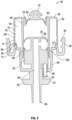
- the pressure within the fluid chamber 60 decreases. This creates a pressure differential between the fluid chamber 60 and the fluid reservoir 34, causing the relatively higher pressure fluid 26 within the reservoir 34 to push the inlet flange 78 of the inlet valve 52 downwards and inwards, allowing the fluid 26 to enter the fluid chamber 60 from the reservoir 34 through the opening 80. This fills the fluid chamber 60 with fluid 26, and thus readies the pump assembly 36 to dispense another allotment of fluid 26 when activated again.
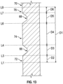
- the air whistle 54 emits little or no sound.
- the second time period as the sealing edge 92 moves along the second portion 74 of the inner surface 70 from location L4 to location L6, travelling distance D4, the air whistle 54 emits the second sound 30.
- the second intermediate time period as the sealing edge 92 moves axially adjacent to the second annular groove 68 from location L6 to location L7, travelling distance D5, the air whistle 54 again emits little or no sound.
- the pump assembly 36 may also be operated multiple times in a row, with incomplete outstroke movements in between. For example, after an initial complete instroke movement, the actuator panel 24 may not be fully released by the user, causing the second instroke movement to begin before the piston body 50 has had a chance to return to the extended first position shown in Figure 4 .
- the sealing edge 92 may, for example, only move from location L9 to location L4 during the incomplete outstroke movements. The subsequent instroke movements would thus only move from location L4 to location L9, causing the air whistle 54 to emit only the second 30 and third sounds 32, without emitting the first sound 28. Again, the amount of fluid 26 dispensed during these abbreviated instroke movements would be less than that dispensed during a complete instroke movement.
- the air pump 37 delivers both of the two streams of air through the sound generator mechanism 702 on movement of the actuator 700 in the cycle of operation in the first stroke.
- the sound generator mechanism 702 produces the two sounds 28, 30 as the actuator 700 is moved in the first stroke, with each sound 28, 30 produced in a different non-overlapping time period during the first stroke than the time period of the other sound 28, 30.
- the time period of each sound 28, 30 in the first stroke is a function of the relative location of the actuator 700 between the first position and the second position.
- the sound sensing mechanism 14 is spaced from the fluid dispenser 12 in a facility where the monitoring of hand cleaning activities is desired, such as a hospital, clinic, long term care facility, restaurant, or day care.
- the sound sensing mechanism 14 incorporates a sound sensor 15 that is configured to detect the first 28, second 30, and third sounds 32 emitted by the air whistle 54 when the fluid dispenser 12 is activated.
- the sound sensing mechanism 14 is communicatively linked to the remote computer 16, and is configured to transmit data representative of the detected sounds 28, 30, 32 to the computer 16.
- the sound sensing mechanism 14 is preferably wirelessly connected to the computer 16 via a Wi-Fi connection or the like, but could also use a wired connection.
- the computer 16 may be located within the same facility as the sound detecting mechanism 14, or could be located in a different area altogether and connected to the sound sensing mechanism 14 through the internet.
- the computer 16 is configured to analyze the detection data transmitted by the sound sensing mechanism 14 in order to distinguish detection data that represents an activation of the fluid dispenser 12 from detection data that represents other environmental sounds detected by the sound sensing mechanism 14.
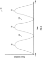
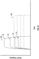
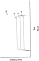
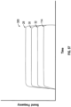
- activation of the fluid dispenser 12 produces a distinct sound profile 98, consisting of the first 28, second 30, and third sounds 32 temporally spaced from one another, with first 100 and second quiet periods 102 in between.
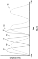
- This distinctive sound profile 98 is used by the computer 16 to distinguish activations of the fluid dispenser 12 from other sounds, such as the environmental sound profile 104 shown in Figure 10 .
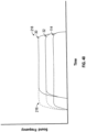
- This sound profile 104 could be produced, for example, by a cough, a toilet flushing, or a door closing in the vicinity of the sound sensing mechanism 14.
- the computer 16 can also distinguish activations of the fluid dispenser 12 from environmental sounds when the dispenser 12 is operated with shortened or incomplete strokes, without requiring the precise sound profile 98 shown in Figure 9 .
- a partial depression of the actuator panel 24 producing the modified sound profile 108 shown in Figure 11 , in which the third sound 32 is omitted could be distinguished from the environmental sound profile 104 shown in Figure 10 based on the presence of distinct first 28 and second sounds 30, with quiet period 100 there between.
- the computer 16 can be configured to recognize the modified sound profile 106, and to calculate or estimate various parameters based on the resulting detection data. For example, the number and timing of the detected sounds 28, 30, 32 can be used to estimate the movement distance of the piston body 50. This, in turn, can be used to estimate the volume of fluid 26 that was dispensed.
- the movement of the air displacement body 84 in an instroke movement at the faster speed may furthermore increase the pressure within the air chamber 64 compared to that when the actuator panel 24 is moved at the predetermined normal speed, thus delivering streams of air through the air whistle 54 at higher pressures.
- the computer 16 can be configured to recognize one or more of these effects in the detection data received from the sound sensing mechanism 14, and to calculate or estimate parameters such as the speed of the instroke movement or the pressure change within the air chamber 64 based thereon.
- the computer 16 is programmed to recognize different sound profiles 98, even when the sound profiles 98 are not uniform.
- the computer 16 may, for example, be programmed to recognize a set of predetermined threshold parameters that are found in a wide range of possible sound profiles 98 as indicating that the dispenser 12 has been activated, the parameters being selected to nonetheless distinguish activations of the dispenser 12 from other environmental sounds.
- the computer 16 may be programmed to recognize individual users and/or types of users based on their sound profiles 98. For example, individual users may operate the dispenser 12 in a unique and recognizable manner that produces a distinct sound profile 98.
- a first user might, for example, always dispense two allotments of fluid 26 using two complete instroke movements, pressing the actuator panel 24 at a uniform and moderate pace.
- a second user might always dispense five allotments of fluid 26 using five partial instroke movements at a rapid pace.
- These uses of the dispenser 12 will produce different sound profiles 98, which could be used to associate the compliance data with particular individuals.
- the data could also be used to generate general information about how the dispenser 12 is used, including information about the frequency of partial strokes, rapid strokes, slow strokes, and multiple strokes.
- the compliance monitoring system 10 would normally incorporate multiple fluid dispensers 12, multiple sound sensing mechanisms 14, and, in some embodiments, multiple computers 16.
- the system 10 could include, for example, a separate sound sensing mechanism 14 in each room of a monitored facility, each sound sensing mechanism 14 being positioned to detect the activation of multiple fluid dispensers 12 located nearby.
- the detection data from each sound sensing mechanism 14 could then be compiled by one or more computers 16 to produce compliance data representative of the entire facility.
- the data from the sound sensing mechanisms 14 could furthermore be combined with data from other compliance monitoring devices, such as hand cleaning devices that electronically record and transmit their own activation data.
- different fluid dispensers 12 could be configured to produce different sound profiles 98, so that the computer 16 could identify the specific fluid dispenser 12 that was activated based on the resulting detection data.
- the system 10 could include both manually operated and touchlessly operated dispensers 12, with the touchlessly operated dispensers 12 producing recognizable sound profiles 98 because of their uniform and predictable instroke speeds, and thus being distinguishable from the sound profiles 98 of the manually operated dispensers 12. Being able to identify the specific dispenser 12 that has been activated allows the computer 16 to produce more specific compliance data. This data may be used, for example, to help determine whether an infrequently used dispenser 12 should be relocated or more prominently displayed.
- the actuation flange 42 is movable relative to the piston body 50, and can be secured to the body 50 at different axial heights relative to the sealing edge 92.
- the actuation flange 42 could be provided as a separate movable element that is threaded to the lower end of the piston body 50, rather than being integrally formed therewith as shown.
- the actuation flange 42 could be provided with a central opening about the axis 59, with a radially inwardly facing surface of the opening having a helical thread that extends radially towards the axis 59 for engagement with a complementary thread formed on the outer surface of the piston body 50.
- the actuation flange 42 By turning the threaded actuation flange 42 in a clockwise or a counterclockwise direction about the axis 59, the actuation flange 42 could be displaced upwards or downwards relative to the piston body 50. The actuation flange 42 could then be locked in place at the selected axial height using a lock nut or the like.
- the location of the sealing edge 92 relative to the inner surface 70 of the outer wall 62 can be altered, thereby causing the dispenser 12 to produce a different sound profile 98 during activation.
- the edge 92 will sit at the higher location L2 when the piston body 50 is in the extended first position, rather than the lower location L1. This will cause the sealing edge 92 to move a reduced distance along the inner wall 70 during the instroke movement, from location L2 to location L9 instead of from location L1 to location L9.
- the dispensers 12 can be made to produce different sound profiles 98 when activated. This would allow the computer 16 to identify the specific dispenser 12 that has been activated, and thereby produce more specific compliance data as described above. Other modifications could be used to achieve much the same effect, such as by adjusting the support assembly 38 so that the movable seat 40 cycles through a different set of heights during the activation of different dispensers 12. Touchlessly operated dispensers 12 could also be configured to move the piston body 50 at different speeds, to produce uniquely identifiable sound profiles 98.
- the first annular groove 66 has been relocated axially outwards
- the second annular groove 68 has been relocated axially inwards.
- This configuration of the grooves 66, 68 shortens the distance D2 that the sealing edge 92 travels along the first portion 72 of the inner surface 70 when moving from location L1 to location L3 during the instroke movement. It also increases the distance D4 between location L4 and location L6, and decreases the distance D6 between location L7 and location L9.
- the shortened distance D2 causes the first sound 28 to have a shorter duration than in the first embodiment. Furthermore, since the sealing edge 92 reaches the first annular groove 66 earlier than in the first embodiment, the air within the air chamber 64 does not become as pressurized as in the first embodiment. This causes the first sound 28 to have a lower sound amplitude.
- the lengthened distance D4 likewise causes the second sound 30 to have a longer duration and a higher amplitude, while the shortened distance D6 causes the third sound 32 to have a shorter duration and a lower amplitude, in comparison with the first embodiment.
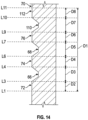
- a third annular groove 110 has been added, and the first 66 and second annular grooves 68 have been relocated axially outwards and positioned closer together.
- This configuration shortens the distances D2, D4, and D6, and further divides the inner surface 70 of the outer wall 62 into a fourth portion 112, located above the third annular groove 110.
- the sealing edge 92 moves axially inwards and upwards along the inner surface 70 of the outer wall 62 from location L1 to location L11, producing the third sound profile 118 shown in Figure 17 .
- the pump assembly 36 produces the first 28, second 30, and third sounds 32, in a similar manner as in the first embodiment, with the shortened distances D2, D4, and D6 causing the first 28, second 30, and third sounds 32 to have a shortened duration and lower amplitude than in the first embodiment.
- the sealing edge 92 reaches and moves axially past the fourth annular groove 110 from location L9 to location L10, travelling distance D7, the air whistle 54 again emits little or no sound, producing the third quiet period 122 shown in Figure 17 .
- the air whistle 54 emits a fourth sound 114. Additional grooves could also be added to cause the pump assembly 36 to emit additional sounds.
- the number of grooves could also be reduced, as in the fourth embodiment shown in Figure 15 .
- the second annular groove 68 has been removed, and the first annular groove 66 has been relocated axially inwards.
- This configuration lengthens the distances D2 and D4, and causes the pump assembly 36 to emit only the first 28 and second sounds 30, producing the fourth sound profile 120 shown in Figure 18 .
- the lengthened distances D2 and D4 cause the first 28 and second sounds 30 to have a longer duration and a higher amplitude than in the first embodiment.
- the piston chamber forming body 48 could be configured so that the air chamber 64 expands during the instroke movement and contracts during the outstroke movement. This could be achieved, for example, by defining the air chamber 64 axially outwards and downwards from the sealing edge 92, so that the instroke movement of the sealing edge 92 expands the air chamber 64 instead of compressing it.
- the air whistle 54 could also be configured to emit the first 28, second 30, and third sounds 32 while the air is moving into the air chamber 64 through the whistle 54, instead of while the air is being expelled. This could be achieved, for example, by reversing the orientation of an air whistle 54 that only produces sounds when air flows through the whistle 54 in a single direction, or by using an air whistle 54 that produces sounds when air flows through the whistle 54 in either direction.
- the line graph shown in Figure 9 depicts the instroke movement as having a duration of approximately one second, the invention is in no way limited to this duration. Different users may push the actuator panel 24 at significantly different speeds, causing the instroke movement to be much shorter or much longer than one second.
- the computer 16 is preferably configured to recognize a wide range of sound profiles 98 corresponding to different instroke speeds and durations, so as to produce accurate compliance data. In some embodiments of the invention, a typical duration of the instroke movement may be much longer or much shorter than 1 second.
- the fluid dispenser 12 is not limited to the specific construction that has been described and illustrated herein. Any fluid dispenser 12 that is operable to produce at least two sounds while dispensing fluid 26 could be used instead.
- the pump assembly 36 has been described and illustrated as having a construction similar to the pump disclosed in United States Patent No. 5,373,970 to Ophardt , other constructions such as those described in U.S. Patent No. 8,816,860 to Ophardt et al., issued August 26, 2014 ; U.S. Patent No. 8,976,031 to Ophardt, issued March 10, 2015 ; U.S. Patent Application Publication No. 2016/0097386 to Ophardt et al., published April 7, 2016 ; U.S. Patent Application Publication No.
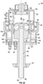
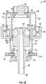
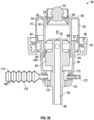
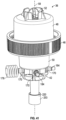
- FIG. 19 to 22 An example of an alternative construction is the fifth embodiment of the invention shown in Figures 19 to 22 , which provides a fluid pump 35 and two air pumps 37 and 137.
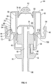
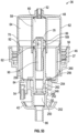
- the pump assembly 36 shown in Figures 19 to 22 is identical to the pump assembly 36 shown in Figure 4 , except for the following notable differences: the grooves 66, 68 are omitted; the outer wall 62 of the piston chamber forming body 48 has a lower section 144 that extends downwardly from the gripping collar 46; the piston body 50 includes both a first air displacement body 84 and a second air displacement body 85; and the piston body 50 uses two distinct air whistles 54 and 55 to produce the first 28 and second 30 sounds, respectively.
- Like numerals are used to identify like features.
- the piston body 50 has two air displacement bodies 84 and 85 for displacing the air within the first air chamber 64 and the second air chamber 65, respectively, and also respectively forming the first air pump 37 to draw and discharge air through the first air whistle 54 and the second air pump 137 to draw and discharge air through the second air whistle 55.
- the first air displacement body 84 extends upwards towards the upper section 140 of the outer wall 62 and has a first sealing edge 92 that is configured to sealingly engage with the inner surface 60 of the upper section 140.
- the second air displacement body 85 extends radially outwardly from the first air displacement body 84 towards the lower section 144 of the outer wall 62 and has a second sealing edge 93.
- the upwards movement of the fluid displacement body 82 within the fluid chamber 60 pressurizes the fluid 26 and forces the fluid 26 out through the fluid outlet 86.
- the upwards movement of the first air displacement body 84 within the first air chamber 64 also pressurizes the air within the first air chamber 64, thus delivering a first stream of pressurized air though the first air whistle 54, and causing the first air whistle 54 to emit the first sound 28.
- the first sealing edge 92 remains engaged with the inner surface 70 of the upper section 140 during the entire instroke movement.
- the first air whistle 54 therefore emits the first sound 28 during a first time period that spans the entire instroke movement, as the piston body 50 moves from the extended first position shown in Figure 20 to the retracted second position shown in Figure 22 .
- the pump assembly 36 can be used for dispensing fluid 26 from a housing 18 similar to the one shown in the first embodiment of the invention.
- the piston body 50 moves coaxially inwardly and upwards relative to the piston chamber forming body 48 in an instroke movement, as in the previously described embodiments.
- This moves the fluid displacement body 82 upwards and axially inwardly within the fluid chamber 60 and moves the air displacement body 84 upwards and axially inwardly within the air chamber 64.
- the upwards movement of the fluid displacement body 82 within the fluid chamber 60 pressurizes the fluid 26 and forces the fluid 26 out through the fluid outlet 86.
- the sounds 30, 32, 114 remain closer to the same frequencies even when the instroke movement is very rapid can be used to assist the computer 16 to recognize the sound profile 206 as an activation of the pump assembly 36. Since the air exits the air chamber 64 more rapidly during a rapid instroke, the sounds 30, 32, 114 have a shorter duration than in the sound profile 204 produced during a normal instroke.
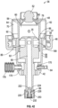
- the pressure relief valve 176 has been replaced by a modular air accumulating bellows 178.
- the bellows 178 has an accordion-like shape and is resiliently expandable from the contracted state shown in Figure 27 to the expanded state shown in Figure 28 .
- the bellows 178 define an internal air cavity 180 that is in fluid communication with the air chamber 64.
- the air cavity 180 has a larger volume in the expanded state than in the contracted state.
- the bellows 178 is resiliently biased towards the contracted state, and only expands towards the expanded state when the air pressure within the air chamber 64 exceeds a preselected threshold adequate to overcome the bias.
- the bellows 178 is configured to return to the contracted state, releasing the collected pressurized air back into the air chamber 64.
- the accumulation of pressurized air within the bellows 178 can assist in keeping the pressure within the air chamber 64 at or below the threshold pressure, and thus acts to moderate fluctuations in the frequencies of the sounds 30, 32, 114 produced by the air whistles 55, 172, 164 when the pump assembly 36 is activated at different velocities, similarly to the pressure relief valve 176. Furthermore, the return of the accumulated pressurized air from the bellows 178 to the air chamber 64 may help to moderate fluctuations in the durations of the sounds 30, 32, 114, since the pressurized air from the bellows 178 is forced out through the air whistles 55, 172, 174 at the end of the instroke rather than bypassing the whistles 55, 172, 174 as in the previous configuration.
- the bellows 178 is configured so that it expands minimally before the threshold pressure is reached, and expands rapidly once the threshold pressure is reached. This helps to keep the pressure within air chamber 64 at or below the threshold pressure, since the entire volume of the expanded bellows 178 is available to accumulate air displaced from the chamber 64 at or near the threshold pressure.
- the resistance of the bellows 178 to expansion may significantly increase as the bellows 178 expands, so that the fully expanded state is only reached at well above the threshold pressure.
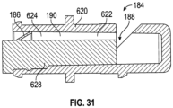
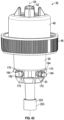
- the modular air whistles 54, 55, 172, 174 and the ports 170 are configured so that the whistles 54, 55, 172, 174 can be received within the ports 170 in the forwards orientation shown in Figures 24 to 28 , or alternatively, in the backwards orientation shown in Figure 29 .
- the whistles 54, 55, 172, 174 produce the sounds 28, 30, 32, 114 as air is drawn from the atmosphere into the air chamber 64 through the whistles 54, 55, 172, 174, rather than when air is expelled from the air chamber 64 out through the whistles 54, 55, 172, 174.
- the air whistles 54, 55, 172, 174 each have an air channel 190 that delivers air to a sound generating portion 188.
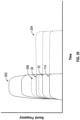
- the configuration shown in Figure 29 produces the sound profile 212 shown in Figure 38 .
- the sound profile 212 is generally similar to that shown in Figure 34 , with the exception that the sounds 30, 32, 114 are produced during the outstroke movement rather than the instroke.
- the pump assembly 36 may be configured to draw air into the air chamber 64 through the whistles 55, 172, 174 to produce the sounds 30, 32, 114 during the instroke movement rather than the outstroke movement.
- the configuration shown in Figure 29 produces three sounds 30, 32, 114 instead of four because a plug 182 has been inserted into the remaining port 170.
- the plug 182 forces more air to pass through each whistle 55, 172, 174, in comparison with a configuration using four whistles 54, 55, 172, 174 instead of three, and thus helps to ensure that the air streams passing through the whistles 55, 172, 174 are forceful enough to generate the sounds 30, 32, 114.
- Plugs 182 can also be used to alter the sound profile 200 produced by the pump assembly 36 by removing one or more of the sounds 28, 30, 32, 114, and thus allow for an even greater variety of unique sound profiles 200 for the purpose of compliance monitoring.
- a very slow instroke movement may cause the air passing through the air whistles 54, 55, 172, 174 to pass through at a rate that is too slow to generate the sounds 28, 20, 32, 114.
- This problem becomes more severe as the number of air whistles 54, 55, 172, 174 increases, since each whistle 54, 55, 172, 174 expels a smaller share of the air displaced by the air displacement body 84 as the number of whistles 54, 55, 172, 174 increases.
- the pressure opening air whistle 184 has a generally cylindrical whistle chamber forming body 620 defining an internal whistle chamber 622.
- the whistle chamber 622 has an air channel forming portion 624 that is open to the air chamber 64 and a sound generating portion 188 that is open to the atmosphere.
- An air channel narrowing body 628 is inserted into the air channel forming portion 624.
- the pressure opening valves 186 could be configured to open at different threshold pressures. This would cause the sounds 28, 30, 32, 114 to begin at different times during the instroke movement, when the whistles 184 are oriented forwardly, as the pressure within the air chamber 64 reaches and is maintained at or above each respective threshold pressure.
- a wide variety of sound profiles 200 could be produced for uniquely identifying different pump assemblies 36 and collecting more detailed compliance monitoring data.
- the sound profiles 200 could also be used to gather additional information about the operation of the pump assemblies 36, with the number and frequency of the sounds 28, 30, 32, 114 being used to determine the air pressure that was reached within the air chamber 64 during activation.
- the resistance generator 220 comprises a molded pressurizing valve 228 in place of the spring-loaded valve 222.
- This embodiment is otherwise identical to the previous embodiment (although different modular components are shown in the ports 170).
- the molded pressurizing valve 228 is fixed within the outlet channel 90 by being secured at its outer end in an inwardly extending central socket of the aperture plate 232.
- the valve 228 has an annular resiliently deformable pressurizing flange 230 that is angled axially downwards and radially outwards into fluid tight engagement with the annular inner surface of the outlet channel 90.
- the size of the apertures 234 may, for example, be selected to provide significant resistance against the flow of fluid 26 through the aperture plate 232 above a preselected threshold flow rate, while providing minimal resistance below that flow rate, with the preselected threshold flow rate corresponding to a preselected velocity of the piston body 50 during the instroke movement. This arrangement helps to keep the instroke movement at or below the preselected velocity, even when the actuator panel 24 is depressed forcefully, and thus leads to more consistent sound profiles 200 for compliance monitoring.
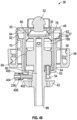
- a pump assembly 36 in accordance with a ninth embodiment of the invention is shown in Figure 46 .
- This embodiment is identical to the pump assembly 36 shown in Figure 27 , but lacks the modular ports 170 and incorporates only a single air whistle 54 in fluid communication with the air chamber 64.
- the pump assembly 36 is operated in an identical manner as the configuration shown in Figure 27 , with the bellows 178 expanding when the pressure within the air chamber 64 exceeds a preselected threshold, to moderate fluctuations in the sound 28 produced by the air whistle 54.
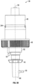
- the pump assembly 36 includes two air whistles 54, 55 that produce the first and second sounds 28, 30 simultaneously, with each air stream coming from a separate air chamber 64, 65.
- the first annular air chamber 64 is defined between the inner wall 58 and the outer wall 62 of the piston chamber forming body 48.
- the first air whistle 54 is positioned adjacent to the fluid displacement body 82, and is in fluid communication with the first air chamber 64.
Abstract
Description
- This invention relates to dispensers, and more particularly to hand cleaning fluid dispensers that generate sounds for the purpose of compliance monitoring.
- The present inventors have appreciated that proper compliance monitoring of hand washing requires monitoring of all hand cleaning dispensers within any particular facility or environment to be monitored, including dispensers that are not connected to a power source. To at least partially overcome the disadvantages of previously known devices, the inventors previously disclosed in
United States Patent No. 8,816,860 to Ophardt et al. , which is hereby incorporated by reference, a fluid dispenser having a sound generator that generates a sound when the dispenser is activated. The sound is then sensed by a sound sensor, and data representative of the sensed sound is transmitted to a computer for compliance monitoring. - The present invention is an improvement over the fluid dispenser and compliance monitoring system as disclosed in
U.S. 8,816,860 . The improvements include providing at least two sounds in a cycle of operation by providing pressurized air to the same sound generator in temporally separated blasts and/or by providing two or more sound generators each to receive pressurized air in a cycle of operation. Further improvements include enhancing the operation of one or more sound generators by providing pressure stabilizing components towards preventing air pressures in an air pump chamber from exceeding a maximum pressure, as by providing a pressure relief valve and/or to reduce air pressures in an air pump chamber when a threshold pressure is reached, as by providing an air accommodating bellows open to the air chamber and/or to controlling air pressure delivered to a sound generator by providing a pressure opening valve upstream of the sound generator which prevents air from passing to the sound generator unless the air pressure exceeds a threshold pressure. The inventors have appreciated that having a fluid dispenser which produces at least two sounds when activated permits the sounds to be more readily identified and distinguished from other environmental sounds. This is useful for improving the accuracy of the compliance monitoring data. Producing at least two sounds also creates a richer sound profile, which can be used in at least some embodiments of the invention to calculate the dosage of fluid that was dispensed, and the distance and speed of movement of the actuator. This is useful for improving the detail and comprehensiveness of the compliance monitoring data, and may be useful for other purposes as well. - The inventors have furthermore appreciated that the at least two sounds can be usefully generated, without requiring an electric power source, by providing an air pump that delivers a first stream of air through the sound generator during a first time period and delivers a second stream of air through the sound generator during a second time period, each time period being a function of the relative location of an actuator between a first position and a second position.
- Optionally, the sound generator may be provided in the form of an air whistle, with the actuator configured to force compressed air through the air whistle to produce the at least two sounds during movement from the first position to the second position. The air pump may incorporate a sealable air passage that allows the compressed air to discharge directly from the air pump when the passage is open, thus bypassing the air whistle. The air pump may furthermore be configured to seal the air passage during both the first time period and the second time period, and to unseal the air passage during a first intermediate time period between the first time period and the second time period. The discharge of compressed air through the unsealed air passage reduces or eliminates the air flow through the air whistle during the first intermediate time period, resulting in distinct first and second sounds being produced by the air whistle during the first and second time periods, respectively, with little or no sound being produced in between.
- The invention also provides fluid dispensers that incorporate multiple sound generators to produce multiple sounds during movement of the actuator. The sounds differ from each other in detectable ways, such as by having a different duration, frequency, temporal alignment, amplitude, and/or timbre. This results in the fluid dispensers producing unique sound profiles that can be used for compliance monitoring, for uniquely identifying different fluid dispensers within a facility, and for collecting additional information about the operation and use patterns of those dispensers.
- The invention furthermore provides dispensers that incorporate pressure stabilizing components that maintain air pressures within air chambers and/or sound generators of the dispensers within a preferred range, so as to moderate fluctuations in the sound profiles that are produced. This helps to ensure that the sound profiles can be recognized by a computer, such as for compliance monitoring, even when components of the dispenser, such as the actuator, are moved differently, for example when operated at a wide variety of different speeds.
- In some embodiments, the fluid dispensers of the present invention are configured to generate foam as well as sounds when activated. The inventors have appreciated that a single air chamber can be used for both of these purposes, with the air entering the chamber being used to generate one or more sounds, and the air exiting the chamber being used to generate foam. In other embodiments, the air exiting the air chamber can be used to generate sounds and to generate foam. The fluid dispensers can also incorporate multiple air chambers, with the air from some chambers being used to generate sounds and the air from other chambers being used to generate foam.
- In still other embodiments, the invention provides dispensers that include one or more sound generators permanently installed within a housing of the dispenser, the housing being configured to receive a replaceable fluid pump and reservoir. One or more additional sound generators may be incorporated into the replaceable fluid pump. The inventors have appreciated that this arrangement of sound generators permits additional information to be collected from the resulting sound profile, including the kind or identity of the dispenser being activated, the kind or identity of the replaceable fluid pump that is installed in the housing, and whether or not an unauthorized fluid pump has been installed.
- Accordingly, in one aspect the present invention resides in a fluid dispenser comprising:
- a fluid pump for drawing fluid from a reservoir and dispensing the fluid on movement of an actuator in a cycle of operation;
- a sound generator mechanism which generates two sounds on movement of the actuator in the cycle of operation, the sound generator mechanism being configured to produce each sound from a respective one of two streams of air passing through the sound generator mechanism; and
- an air pump mechanism for delivering the two streams of air through the sound generator mechanism on movement of the actuator in the cycle of operation.
- In some embodiments, in the cycle of operation to dispense a dose of the fluid, the actuator is moved between a first position and a second position; and
the sound generator mechanism produces the two sounds as the actuator is moved from the first position to the second position, with each sound produced in a different time period during the cycle of operation than the other sound, the time period of each sound in the cycle of operation being a function of the relative location of the actuator between the first position and the second position. - In some preferred embodiments, the air pump mechanism delivers one of the streams of air through the sound generator mechanism as a first air stream during a first time period when the actuator moves between the first position and a first intermediate position between the first position and the second position; and
the air pump mechanism delivers one of the streams of air through the sound generator mechanism as a second air stream during a second time period different than the first time period when the actuator moves between the first intermediate position and a second intermediate position between the first intermediate position and the second position. - The air pump mechanism may optionally comprise:
- an air chamber forming body in fluid communication with the sound generator mechanism;
- an air passage for carrying air between the air chamber forming body and an air source; and
- a sealing body configured to seal the air passage during the first time period and during the second time period, and to unseal the air passage during a first intermediate time period between the first time period and the second time period.
- In some embodiments, the actuator is configured to reduce a volume of air contained within the air chamber forming body during movement from the first position to the second position, forcing at least some of the air to discharge from the air chamber forming body;
wherein: - during the first time period the air is discharged through the sound generator mechanism as the first air stream;
- during the first intermediate time period at least some of the air is discharged through the unsealed air passage, thereby reducing or eliminating air flow through the sound generator mechanism; and
- during the second time period the air is discharged through the sound generator mechanism as the second air stream.
- Optionally, the sound generator mechanism may produce a first sound during the first time period, produce little or no sound during the first intermediate time period, and produce a second sound during the second time period.
- In some embodiments, the actuator may comprise a piston body, wherein movement of the actuator from the first position to the second position comprises an instroke movement of the piston body within the air chamber forming body, thereby pressurizing the air contained within the air chamber forming body and forcing at least some of the air to discharge from the air chamber forming body.
- The air passage is optionally defined between the piston body and the air chamber forming body;
- wherein the air chamber forming body comprises a sealing zone and an unsealing zone;
- wherein the piston body is configured to sealingly engage with the air chamber forming body when positioned within the sealing zone, thereby sealing the air passage; and
- wherein the piston body is configured to at least partially disengage from the air chamber forming body when positioned within the unsealing zone, thereby unsealing the air passage.
- In some embodiments, the air chamber forming body comprises a cylindrical outer wall, the outer wall having a first diameter in the sealing zone and a second diameter in the unsealing zone, the second diameter being larger than the first diameter;
wherein the piston body comprises an outer edge that is configured to sealingly engage with the air chamber forming body when positioned within the sealing zone, and to at least partially disengage from the air chamber forming body when positioned within the unsealing zone. - The sealing zone may optionally comprise a first sealing area and a second sealing area, and wherein the unsealing zone comprises a first unsealing area;
wherein the instroke movement of the piston body comprises: - a first segment of movement in which the outer edge of the piston body moves along and sealingly engages with the first sealing area of the air chamber forming body, thereby compressing the air contained within the air chamber forming body and forcing the first air stream through the sound generator mechanism;
- a second segment of movement in which the outer edge of the piston body moves past the first unsealing area of the air chamber forming body, thereby unsealing the air passage and allowing the air contained within the air chamber forming body to discharge through the air passage, reducing or eliminating the air flow through the sound generator mechanism; and
- a third segment of movement in which the outer edge of the piston body moves along and sealingly engages with the second sealing area of the air chamber forming body, thereby compressing the air contained within the air chamber forming body and forcing the second air stream through the sound generator mechanism.
- The sealing zone may further comprise a third sealing area, and wherein the unsealing zone further comprises a second unsealing area;
wherein the instroke movement of the piston body further comprises: - a fourth segment of movement in which the outer edge of the piston body moves past the second unsealing area of the air chamber forming body, thereby unsealing the air passage and allowing the air contained within the air chamber forming body to discharge through the air passage, reducing or eliminating the air flow through the sound generator mechanism; and
- a fifth segment of movement in which the outer edge of the piston body moves along and sealingly engages with the third sealing area of the air chamber forming body, thereby compressing the air contained within the air chamber forming body and forcing a third air stream through the sound generator, causing the sound generator mechanism to produce a third sound.
- Optionally, the sound generator mechanism comprises an air whistle.
- In some embodiments, the fluid dispenser is a manually operated dispenser in which the actuator is moved by a user to dispense fluid, and the fluid is a hand cleaning fluid.
- In another aspect, the present invention resides in a system for monitoring activation of a fluid dispenser, comprising:
- the aforementioned fluid dispenser; and
- a sound sensing mechanism spaced from the fluid dispenser, comprising:
- a sound sensor to sense the two sounds produced by the sound generator mechanism; and
- a communication mechanism to transmit data representative of the sounds sensed by the sound sensor to a remote computer.
- In some embodiments, the computer may be configured to calculate a volume of the fluid dispensed from the fluid dispenser based on a sound profile of the two sounds; to identify the fluid dispenser based on a sound profile of the two sounds; to distinguish the two sounds from other sounds based on a sound profile of the two sounds; to calculate a movement speed of the actuator based on a sound profile of the two sounds; or to calculate a movement distance of the actuator based on a sound profile of the two sounds.
- In another aspect, the present invention resides in a fluid dispenser comprising:
- a fluid pump for dispensing fluid on movement of an actuator activated by a user;
- a first sound generator which generates a first sound when the fluid dispenser is activated by the user, the first sound generator being configured to produce the first sound from a first stream of air passing through the first sound generator;
- a second sound generator which generates a second sound when the fluid dispenser is activated by the user, the second sound generator being configured to produce the second sound from a second stream of air passing through the second sound generator; and
- at least one air pump for passing the first stream of air through the first sound generator and the second stream of air through the second sound generator on movement of the actuator;
- wherein in a cycle of operation to dispense a dose of the fluid, the actuator is moved between a first position and a second position; and
- wherein the first sound generator produces the first sound as the actuator is moved from the first position to the second position, and the second sound generator produces the second sound as the actuator is moved from the first position to the second position.
- Preferably, the first sound differs from the second sound in respect of at least one detectable sound characteristic. The at least one detectable sound characteristic may comprise, for example, at least one of: duration, frequency, temporal alignment, amplitude, and timbre.
- Optionally, the first sound generator produces the first sound during a first time period and the second sound generator produces the second sound during a second time period, the first time period being different than the second time period, the time period of each sound in the cycle of operation being a function of the relative location of the actuator between the first position and the second position.
- In some embodiments, the at least one air pump delivers the first stream of air through the first sound generator during the first time period when the actuator moves from a first sound start position to a first sound end position; and the at least one air pump delivers the second stream of air through the second sound generator during the second time period when the actuator moves from a second sound start position to a second sound end position.
- The first sound start position may, for example, be the first position, and the first sound end position may, for example, be the second position. The second sound start position may, for example, be between the first position and the second position, and the second sound end position may, for example, be the second position.
- In some embodiments, the at least one air pump comprises:
- a first air chamber forming body in fluid communication with the first sound generator;
- a second air chamber forming body in fluid communication with the second sound generator;
- an air passage for carrying air between the second air chamber forming body and an air source; and
- a sealing body configured to seal the air passage during the second time period.
- The sealing body may be configured to unseal the air passage during an intermediate time period in which the actuator moves from the first sound start position to the second sound start position.
- In some embodiments, the actuator is configured to reduce a volume of air contained within the first air chamber forming body during movement from the first position to the second position, forcing at least some of the air to discharge from the first air chamber forming body through the first sound generator as the first stream of air;
- wherein the actuator is also configured to reduce a volume of air contained within the second air chamber forming body during movement from the first position to the second position, forcing at least some of the air to discharge from the second air chamber forming body;
- wherein during the second time period the air is discharged from the second air chamber forming body through the second sound generator as the second air stream; and
- wherein during the intermediate time period at least some of the air is discharged from the second air chamber forming body through the air passage, thereby reducing or eliminating air flow through the second sound generator and causing the second sound generator to produce little or no sound during the intermediate time period.
- The actuator may, for example, comprise a piston body, wherein movement of the actuator from the first position to the second position comprises an instroke movement of the piston body within the first air chamber forming body and the second air chamber forming body, thereby pressurizing the air contained within the first air chamber forming body and the second air chamber forming body and forcing at least some of the air to discharge from the first air chamber forming body and the second air chamber forming body.
- The air passage may, for example, be defined between the piston body and the second air chamber forming body;
- wherein the second air chamber forming body comprises a sealing zone and an unsealing zone;
- wherein the piston body is configured to sealingly engage with the second air chamber forming body when positioned within the sealing zone, thereby sealing the air passage; and
- wherein the piston body is configured to at least partially disengage from the second air chamber forming body when positioned within the unsealing zone, thereby unsealing the air passage.
- In some embodiments, the second air chamber forming body comprises a cylindrical outer wall, the outer wall having a first diameter in the sealing zone and a second diameter in the unsealing zone, the second diameter being larger than the first diameter;
wherein the piston body comprises an outer edge that is configured to sealingly engage with the second air chamber forming body when positioned within the sealing zone, and to at least partially disengage from the second air chamber forming body when positioned within the unsealing zone. - The outer edge of the piston body may be positioned within the unsealing zone when the piston body is between the first position and the second sound start position, and is positioned within the sealing zone when between the second sound start position and the second position.
- The at least one air pump may comprise an air chamber forming body in fluid communication with the first sound generator and the second sound generator;
wherein the actuator is configured to reduce a volume of air contained within the air chamber forming body during movement from the first position to the second position, forcing at least some of the air to discharge from the air chamber forming body through the first sound generator as the first stream of air and through the second sound generator as the second stream of air. - The actuator may, for example, comprise a piston body, wherein movement of the actuator from the first position to the second position comprises an instroke movement of the piston body within the air chamber forming body, thereby pressurizing the air contained within the air chamber forming body and forcing at least some of the air to discharge from the air chamber forming body.
- Optionally, the piston body comprises a first modular port, a second modular port, and a third modular port, each in fluid communication with the air chamber forming body;
- wherein the first sound generator is received within the first modular port;
- wherein the second sound generator is received within the second modular port; and
- wherein the third modular port is configured to receive at least one of: a third sound generator, a pressure stabilizer, and a plug.
- In some embodiments, the third sound generator is received within the third modular port, the third sound generator being configured to generate a third sound when the fluid dispenser is activated by the user; and
wherein the first sound, the second sound, and the third sound each have a different sound frequency. - The third modular port may be configured to receive the third sound generator in both a forwards orientation and a backwards orientation;
- wherein the third sound generator is configured to generate the third sound during the instroke movement when in the forwards orientation; and
- wherein the third sound generator is configured to generate the third sound during an outstroke movement when in the backwards orientation.
- In some embodiments, the fluid dispenser further comprises a pressure stabilizer in fluid communication with the air chamber forming body, the pressure stabilizer being configured to maintain air pressure within the air chamber forming body below a preselected maximum pressure.
- The preselected maximum pressure is preferably selected to moderate fluctuations in a sound profile produced by the first sound generator and the second sound generator when the fluid dispenser is activated by the user at different velocities.
- The pressure stabilizer may, for example, comprise a pressure relief valve that is configured to release air from the air chamber forming body when the air pressure within the air chamber forming body exceeds a preselected threshold.
- In other embodiments, the pressure stabilizer comprises an air accumulator that is configured to receive air from the air chamber forming body when the air pressure within the air chamber forming body exceeds a preselected threshold.
- The air accumulator is optionally configured to return to the air chamber forming body at least some of the air received from the air chamber forming body when the air pressure within the air chamber forming body falls below the preselected threshold.
- The air accumulator may, for example, comprise a resiliently expandable bellows having an expanded state and a contracted state, the bellows defining an internal volume that is greater in the expanded state than in the contracted state, the bellows being resiliently biased towards the contracted state.
- In some embodiments, the fluid dispenser further comprises a first pressure opening valve that is configured to prevent the first stream of air from passing through the first sound generator until the air within the air chamber forming body exceeds a first preselected minimum pressure.
- The fluid dispenser may further comprise a second pressure opening valve that is configured to prevent the second stream of air from passing through the second sound generator until the air within the air chamber forming body exceeds a second preselected minimum pressure.
- In some embodiments, the at least one air pump comprises an air chamber forming body in fluid communication with the first sound generator and the second sound generator;
wherein the actuator is configured to increase a volume of air contained within the air chamber forming body during movement from the first position to the second position, drawing atmospheric air through the first sound generator as the first stream of air and through the second sound generator as the second stream of air. - The actuator may, for example, comprise a piston body, wherein movement of the actuator from the first position to the second position comprises an outstroke movement of the piston body within the air chamber forming body, thereby producing a vacuum within the air chamber forming body and drawing atmospheric air into the air chamber forming body.
- In some embodiments the fluid dispenser further comprises:
- a fluid chamber containing the fluid to be dispensed; and
- a fluid outlet in fluid communication with the fluid chamber, for dispensing the fluid from the fluid chamber;
- wherein movement of the actuator from the first position to the second position pressurizes the fluid contained within the fluid chamber, forcing an allotment of the fluid to be expelled from the fluid outlet.
- The fluid dispenser may further comprise a resistance generator configured to increase the pressure of the fluid contained within the fluid chamber to provide resistance against movement of the actuator from the first position to the second position, the actuator resisting movement from the first position to the second position as the pressure of the fluid contained within the fluid chamber increases.
- The resistance generator is preferably configured to moderate fluctuations in a sound profile produced by the first sound generator and the second sound generator when the fluid dispenser is activated.
- The resistance generator may, for example, comprise a pressurizing valve that prevents the fluid from being expelled from the fluid outlet until the pressure within the fluid chamber exceeds a minimum fluid pressure. Optionally, the resistance generator comprises a narrowing body that narrows a fluid pathway between the fluid chamber and the fluid outlet or at the fluid outlet. The narrowing body may comprise a plate with one or more apertures, the apertures being sized based on a predetermined fluid viscosity of the fluid, to provide resistance against a flow of the fluid through the apertures.
- In a further aspect, the present invention resides in a fluid dispenser comprising:
- a fluid pump for dispensing fluid on movement of an actuator activated by a user;
- a sound generator which generates a sound when the fluid dispenser is activated by the user, the sound generator being configured to produce the sound from a stream of air passing through the sound generator;
- an air pump for delivering the stream of air through the sound generator on movement of the actuator, the air pump comprising an air chamber forming body in fluid communication with the sound generator; and
- a pressure stabilizer in fluid communication with the air chamber forming body, the pressure stabilizer being configured to maintain air pressure within the air chamber forming body below a preselected maximum pressure;
- wherein in a cycle of operation to dispense a dose of the fluid, the actuator is moved between a first position and a second position; and
- wherein the actuator is configured to reduce a volume of air contained within the air chamber forming body during movement from the first position to the second position, forcing at least some of the air to discharge from the air chamber forming body through the sound generator as the stream of air and causing the sound generator to produce the sound.
- The preselected maximum pressure is preferably selected to moderate fluctuations in a sound profile produced by the sound generator when the fluid dispenser is activated by the user at different velocities.
- The pressure stabilizer may, for example, comprise a pressure relief valve that is configured to release air from the air chamber forming body when the air pressure within the air chamber forming body exceeds a preselected threshold.
- In other embodiments, the pressure stabilizer comprises an air accumulator that is configured to receive air from the air chamber forming body when the air pressure within the air chamber forming body exceeds a preselected threshold.
- The air accumulator is optionally configured to return to the air chamber forming body at least some of the air received from the air chamber forming body when the air pressure within the air chamber forming body falls below the preselected threshold.
- The air accumulator may comprise a resiliently expandable bellows having an expanded state and a contracted state, the bellows defining an internal volume that is greater in the expanded state than in the contracted state, the bellows being resiliently biased towards the contracted state.
- In another aspect, the present invention resides in a fluid dispenser comprising:
- a fluid pump for dispensing fluid on movement of an actuator activated by a user;
- a fluid chamber containing the fluid to be dispensed;
- a fluid outlet in fluid communication with the fluid chamber, for dispensing the fluid from the fluid chamber;
- a sound generator which generates a sound when the fluid dispenser is activated by the user, the sound generator being configured to produce the sound from a stream of air passing through the sound generator; and
- an air pump for delivering the stream of air through the sound generator on movement of the actuator;
- wherein in a cycle of operation to dispense a dose of the fluid, the actuator is moved between a first position and a second position; and
- wherein the air pump is configured to deliver the stream of air through the sound generator when the actuator is moved from the first position to the second position;
- wherein movement of the actuator from the first position to the second position pressurizes the fluid contained within the fluid chamber, forcing an allotment of the fluid to be expelled from the fluid outlet;
- wherein the actuator resists movement from the first position to the second position as the pressure of the fluid contained within the fluid chamber increases; and
- wherein the fluid dispenser further comprises a resistance generator configured to increase the pressure of the fluid contained within the fluid chamber to provide resistance against movement of the actuator from the first position to the second position.
- The resistance generator is preferably configured to moderate fluctuations in a sound profile produced by the sound generator when the fluid dispenser is activated.
- The resistance generator may, for example, comprise a pressurizing valve that prevents the fluid from being expelled from the fluid outlet until the pressure within the fluid chamber exceeds a minimum fluid pressure.
- In a still further aspect, the present invention resides in a fluid dispenser comprising:
- a fluid chamber containing fluid to be dispensed as foam;
- an air chamber containing air for mixing with the fluid to generate the foam;
- a foam generator for receiving and mixing the fluid from the fluid chamber and the air from the air chamber to generate the foam;
- a fluid outlet for dispensing the foam produced by the foam generator;
- at least one pump for dispensing the foam on movement of an actuator activated by a user;
- a sound generator in fluid communication with the air chamber, the sound generator being configured to produce a sound from a stream of air passing through the sound generator; and
- a one-way air inlet valve that permits atmospheric air to enter the air chamber through the sound generator, and prevents the air contained within the air chamber from exiting the air chamber through the sound generator;
- wherein movement of the actuator from a first position to a second position reduces a volume of the air contained within the air chamber, forcing at least some of the air to pass from the air chamber to the foam generator; and
- wherein movement of the actuator from the second position to the first position increases the volume of the air contained within the air chamber, drawing the atmospheric air through the sound generator as the stream of air and causing the sound generator to produce the sound.
- The fluid dispenser may further comprise a one-way air outlet valve that permits the air contained within the air chamber to pass from the air chamber to the foam generator, and prevents the air and the fluid contained within the foam generator from passing from the foam generator to the air chamber.
- The actuator may, for example, comprises a piston body, wherein movement of the actuator from the first position to the second position comprises an instroke movement of the piston body within the air chamber; and
wherein movement of the actuator from the second position to the first position comprises an outstroke movement of the piston body within the air chamber. - Optionally, the foam generator comprises:
- a mixing chamber that receives the fluid from the fluid chamber and the air from the air chamber; and
- a solid foam plug that is positioned between the mixing chamber and the fluid outlet, so that the air and the fluid must pass through the foam plug to generate the foam when dispensed.
- In another aspect, the present invention resides in a fluid dispensing device comprising:
- a replaceable fluid pump operable to dispense fluid; and
- a housing configured to releasably receive the replaceable fluid pump, the housing comprising:
- an actuator configured to dispense the fluid from the fluid pump when activated by a user;
- a sound generator configured to produce a sound from a stream of air passing through the sound generator; and
- an air pump configured to deliver the stream of air through the sound generator when the actuator is activated.
- Optionally, the sound generator comprises a first sound generator, the air pump comprises a first air pump, and the sound comprises a first sound; and
the replaceable fluid pump comprises: - a second sound generator which generates a second sound from a second stream of air passing through the second sound generator; and
- a second air pump configured to deliver the second stream of air through the second sound generator when the actuator is activated.
- Preferably, the first sound differs from the second sound in respect of at least one detectable sound characteristic. The at least one detectable sound characteristic may, for example, comprise at least one of: duration, frequency, temporal alignment, amplitude, and timbre.
- The fluid pump optionally comprises the aforementioned fluid dispenser.
- In some embodiments, the first air pump comprises a resiliently compressible chamber that has an expanded state and a contracted state, the chamber defining an internal volume of air that is greater in the expanded state than in the contracted state, the chamber being biased towards the expanded state; and
- wherein the actuator is configured to compress the chamber from the expanded state to the contracted state when activated, forcing at least some of the air contained within the chamber out through the first sound generator to generate the first sound.
- The actuator may be configured to move from a first position to a second position when activated. The actuator is optionally movable from the first position to the second position by manually pressing the actuator towards the second position; and
wherein the actuator is biased to return to the first position when the manual pressure is removed. - The sound generator may, for example, comprise an air whistle.
- The fluid dispenser is optionally a manually operated dispenser in which the actuator is moved by the user to dispense fluid.
- The fluid may, for example, be a hand cleaning fluid.
- In another aspect, the present invention resides in a system for monitoring activation of a fluid dispenser, comprising:
- the aforementioned fluid dispenser or fluid dispensing device; and
- a sound sensing mechanism spaced from the fluid dispenser, comprising:
- a sound sensor to sense the sounds produced by the fluid dispenser; and
- a communication mechanism to transmit data representative of the sounds sensed by the sound sensor to a remote computer.
- The computer may, for example, be configured to calculate a volume of the fluid dispensed from the fluid dispenser based on a sound profile of the fluid dispenser; to identify the fluid dispenser based on a sound profile of the fluid dispenser; to distinguish the sounds produced by the fluid dispenser from other sounds based on a sound profile of the fluid dispenser; to calculate a movement speed of the actuator based on a sound profile of the fluid dispenser; and/or to calculate a movement distance of the actuator based on a sound profile of the fluid dispenser.
- In a further aspect, the invention resides in a method comprising:
- detecting the sounds produced when the aforementioned fluid dispenser is activated; and
- generating data representing a sound profile of the detected sounds.
- The method may further comprise:
- determining whether the sound profile falls within a predetermined range of expected sound profiles; and
- if the sound profile falls within the predetermined range, recording that the fluid dispenser was activated.
- In some embodiments, the method further comprises identifying the fluid dispenser that was activated based on the sound profile.
- The sound profile preferably includes one or more detectable sound characteristics selected from the group consisting of: duration, temporal alignment, amplitude, frequency, and timbre.
- The method can optionally further comprise calculating an operational parameter of the fluid dispenser based on the sound profile.
- The operational parameter is, for example, selected from the group consisting of: stroke speed, stroke distance, fluid pressure, air pressure, and volume of fluid dispensed.
- In a further aspect, the present invention resides in a fluid dispenser comprising: a fluid pump for drawing fluid from a reservoir and dispensing the fluid on movement of an actuator in a cycle of operation; the actuator reciprocally movable in the cycle of operation between a first position and a second position with movement from the first position to the second position comprising a first stroke and movement from the second position to the first position comprising a second stroke, a sound generator mechanism which generates two sounds on movement of the actuator in the cycle of operation in the first stroke, the sound generator mechanism being configured to produce each sound from a respective one of two streams of air passing through the sound generator mechanism; and an air pump that delivers both of the two streams of air through the sound generator mechanism on movement of the actuator in the cycle of operation in the first stroke; wherein the sound generator mechanism produces the two sounds as the actuator is moved in the first stroke, with each sound produced in a different non-overlapping time period during the first stroke than the time period of the other sound, the time period of each sound in the first stroke being a function of the relative location of the actuator between the first position and the second position.
- Preferably, the air pump delivers one of the streams of air through the sound generator mechanism as a first air stream during a first time period in the first stroke when the actuator moves between the first position and a first intermediate position between the first position and the second position; and wherein the air pump delivers one of the streams of air through the sound generator mechanism as a second air stream during a second time period in the first stroke different than the first time period when the actuator moves between the first intermediate position and a second intermediate position between the first intermediate position and the second position.
- Optionally, the air pump comprises: an air chamber forming body in fluid communication with the sound generator mechanism; an air passage for carrying air into or out of the air chamber forming body; and a sealing body configured to seal the air passage during the first time period and during the second time period, and to unseal the air passage during a first intermediate time period between the first time period and the second time period.
- In some embodiments, the actuator is configured to reduce a volume of air contained within the air chamber forming body during movement in the first stroke from the first position to the second position, forcing at least some of the air to discharge from the air chamber forming body; wherein: during the first time period the air is discharged through the sound generator mechanism as the first air stream; during the first intermediate time period at least some of the air is discharged through the unsealed air passage, thereby reducing or eliminating air flow through the sound generator mechanism; and during the second time period the air is discharged through the sound generator mechanism as the second air stream.
- Preferably, the sound generator mechanism produces a first sound during the first time period, produces little or no sound during the first intermediate time period, and produces a second sound during the second time period.
- Optionally, the actuator comprises a piston body; and wherein movement of the actuator in the first stroke from the first position to the second position comprises an instroke movement of the piston body within the air chamber forming body, thereby pressurizing the air contained within the air chamber forming body and forcing at least some of the air to discharge from the air chamber forming body.
- In some embodiments, the air passage is defined between the piston body and the air chamber forming body; wherein the air chamber forming body comprises a sealing zone and an unsealing zone; wherein the piston body is configured to sealingly engage with the air chamber forming body when positioned within the sealing zone, thereby sealing the air passage; and wherein the piston body is configured to at least partially disengage from the air chamber forming body when positioned within the unsealing zone, thereby unsealing the air passage.
- Preferably, the air chamber forming body comprises a cylindrical outer wall, the outer wall having a first diameter in the sealing zone and a second diameter in the unsealing zone, the second diameter being larger than the first diameter; wherein the piston body comprises an outer edge that is configured to sealingly engage with the air chamber forming body when positioned within the sealing zone, and to at least partially disengage from the air chamber forming body when positioned within the unsealing zone.
- Optionally, the sealing zone comprises a first sealing area and a second sealing area, and wherein the unsealing zone comprises a first unsealing area; wherein the instroke movement of the piston body comprises: a first segment of movement in which the outer edge of the piston body moves along and sealingly engages with the first sealing area of the air chamber forming body, thereby compressing the air contained within the air chamber forming body and forcing the first air stream through the sound generator mechanism; a second segment of movement in which the outer edge of the piston body moves past the first unsealing area of the air chamber forming body, thereby unsealing the air passage and allowing the air contained within the air chamber forming body to discharge through the air passage, reducing or eliminating the air flow through the sound generator mechanism; and a third segment of movement in which the outer edge of the piston body moves along and sealingly engages with the second sealing area of the air chamber forming body, thereby compressing the air contained within the air chamber forming body and forcing the second air stream through the sound generator mechanism.
- In some embodiments, the sealing zone further comprises a third sealing area, and wherein the unsealing zone further comprises a second unsealing area; wherein the instroke movement of the piston body further comprises: a fourth segment of movement in which the outer edge of the piston body moves past the second unsealing area of the air chamber forming body, thereby unsealing the air passage and allowing the air contained within the air chamber forming body to discharge through the air passage, reducing or eliminating the air flow through the sound generator mechanism; and a fifth segment of movement in which the outer edge of the piston body moves along and sealingly engages with the third sealing area of the air chamber forming body, thereby compressing the air contained within the air chamber forming body and forcing a third air stream through the sound generator mechanism, causing the sound generator mechanism to produce a third sound.
- In some embodiments, the actuator comprises a piston body; wherein movement of the actuator from the first position to the second position comprises an outstroke movement of the piston body within the air chamber forming body, which produces a vacuum within the air chamber forming body, thereby causing atmospheric air to be drawn into the air chamber forming body; wherein the sound generator mechanism produces a first sound during the first time period, produces little or no sound during the first intermediate time period, and produces a second sound during the second time period; wherein: during the first time period the atmospheric air is drawn into the air chamber forming body through the sound generator mechanism as the first air stream; during the first intermediate time period the atmospheric air is drawn into the air chamber forming body through the unsealed air passage, thereby reducing or eliminating air flow through the sound generator mechanism; and during the second time period the atmospheric air is drawn into the air chamber forming body through the sound generator mechanism as the second air stream; wherein the air passage is defined between the piston body and the air chamber forming body; wherein the air chamber forming body comprises a sealing zone and an unsealing zone; wherein the piston body is configured to sealingly engage with the air chamber forming body when positioned within the sealing zone, thereby sealing the air passage; wherein the piston body is configured to at least partially disengage from the air chamber forming body when positioned within the unsealing zone, thereby unsealing the air passage; wherein the air chamber forming body comprises a cylindrical outer wall, the outer wall having a first diameter in the sealing zone and a second diameter in the unsealing zone, the second diameter being larger than the first diameter; wherein the piston body comprises an outer edge that is configured to sealingly engage with the air chamber forming body when positioned within the sealing zone, and to at least partially disengage from the air chamber forming body when positioned within the unsealing zone; wherein the sealing zone comprises a first sealing area and a second sealing area, and wherein the unsealing zone comprises a first unsealing area; wherein the outstroke movement of the piston body comprises: a first segment of movement in which the outer edge of the piston body moves along and sealingly engages with the first sealing area of the air chamber forming body, thereby producing a vacuum within the air chamber forming body and drawing the first stream of air through the sound generator mechanism into the air chamber forming body; a second segment of movement in which the outer edge of the piston body moves past the first unsealing area of the air chamber forming body, thereby unsealing the air passage and allowing the atmospheric air to be drawn into the air chamber forming body through the air passage, reducing or eliminating the air flow through the sound generator mechanism; and a third segment of movement in which the outer edge of the piston body moves along and sealingly engages with the second sealing area of the air chamber forming body, thereby producing a vacuum within the air chamber forming body and drawing the second stream of air through the sound generator mechanism into the air chamber forming body.
- Preferably, the fluid dispenser further comprises a fluid chamber containing the fluid to be dispensed; and a fluid outlet in fluid communication with the fluid chamber, for dispensing the fluid from the fluid chamber; wherein movement of the actuator from the first position to the second position pressurizes the fluid contained within the fluid chamber, forcing the dose of the fluid to be expelled from the fluid outlet.
- Optionally, the sound generator mechanism comprises an air whistle.
- In some embodiments, the fluid dispenser is a manually operated dispenser in which the actuator is moved by a user to dispense the fluid.
- Preferably, the fluid is a hand cleaning fluid.
- Further aspects and advantages of the invention will appear from the following description taken together with the accompanying drawings, in which:
-
Figure 1 is a schematic view of a compliance monitoring system in accordance with a first embodiment of the present invention, including a sound generating fluid dispenser and a sound sensing mechanism in communication with a remote computer; -
Figure 2 is a perspective view of the fluid dispenser shown inFigure 1 , with the housing of the fluid dispenser shown in an open condition to reveal the fluid reservoir and pump assembly held therein; -
Figure 3 is a detailed front view of the pump assembly shown inFigure 2 ; -
Figure 4 is a cross-sectional view of the pump assembly shown inFigure 3 , with the pump shown in an extended first position; -
Figure 4a is a detailed cross-sectional view of the outer wall of the pump assembly shown inFigure 4 ; -
Figure 5 is a cross-sectional view of the pump assembly shown inFigure 3 , with the pump shown in a first sealed intermediate position during an instroke movement; -
Figure 6 is a cross-sectional view of the pump assembly shown inFigure 3 , with the pump shown in a first unsealed intermediate position during the instroke movement; -
Figure 7 is a cross-sectional view of the pump assembly shown inFigure 3 , with the pump shown in a second sealed intermediate position during the instroke movement; -
Figure 8 is a cross-sectional view of the pump assembly shown inFigure 3 , with the pump shown in a retracted second position; -
Figure 9 is a line graph depicting the sound profile produced by the fluid dispenser shown inFigure 1 during a normal speed instroke movement; -
Figure 10 is a line graph depicting the sound profile of an environmental sound produced in the vicinity of the sound sensing mechanism shown inFigure 1 , with the sound profile ofFigure 9 shown in dotted lines for comparison; -
Figure 11 is a line graph depicting the sound profile produced by the fluid dispenser shown inFigure 1 during a partial instroke movement, with the sound profile ofFigure 9 shown in dotted lines for comparison; and -
Figure 12 is a line graph depicting the sound profile produced by the fluid dispenser shown inFigure 1 during a rapid speed instroke movement, with the sound profile ofFigure 9 shown in dotted lines for comparison; -
Figure 13 is a detailed cross-sectional view of the outer wall of a pump assembly in accordance with a second embodiment of the invention; -
Figure 14 is a detailed cross-sectional view of the outer wall of a pump assembly in accordance with a third embodiment of the invention; -
Figure 15 is a detailed cross-sectional view of the outer wall of a pump assembly in accordance with a fourth embodiment of the invention; -
Figure 16 is a line graph depicting the sound profile produced by the pump assembly shown inFigure 13 , with the sound profile ofFigure 9 shown in dotted lines for comparison; -
Figure 17 is a line graph depicting the sound profile produced by the pump assembly shown inFigure 14 , with the sound profile ofFigure 9 shown in dotted lines for comparison; -
Figure 18 is a line graph depicting the sound profile produced by the pump assembly shown inFigure 15 , with the sound profile ofFigure 9 shown in dotted lines for comparison; -
Figure 19 is a perspective view of a pump assembly in accordance with a fifth embodiment of the invention; -
Figure 20 is a cross-sectional view of the pump assembly shown inFigure 19 , with the pump shown in an extended first position; -
Figure 21 is a cross-sectional view of the pump assembly shown inFigure 19 , with the pump shown in an intermediate position during an instroke movement; -
Figure 22 is a cross-sectional view of the pump assembly shown inFigure 19 , with the pump shown in a retracted second position; -
Figure 23 is a line graph depicting the sound profile produced by the pump assembly shown inFigure 19 during an instroke movement; -
Figure 24 is a perspective view of a pump assembly in accordance with a sixth embodiment of the invention, configured to incorporate four air whistles; -
Figure 25 is a cross-sectional view of the pump assembly shown inFigure 24 ; -
Figure 26 is a cross-sectional view of the pump assembly shown inFigure 24 , configured to incorporate a pressure relief valve in place of one of the air whistles; -
Figure 27 is a cross-sectional view of the pump assembly shown inFigure 24 , configured to incorporate a pressure stabilizing bellows in place of one of the air whistles; -
Figure 28 is a cross-sectional view of the pump assembly shown inFigure 27 , with the bellows in an expanded state; -
Figure 29 is a cross-sectional view of the pump assembly shown inFigure 24 , configured to replace one of the air whistles with a plug, the remaining air whistles being inverted to generate sounds during an outstroke movement; -
Figure 30 is a cross-sectional view of the pump assembly shown inFigure 24 , configured to replace one of the air whistles with a plug, and with two of the remaining air whistles adapted to incorporate a pressure opening valve; -
Figure 31 is a detailed cross-sectional view of the air whistle adapted to incorporate a pressure opening valve shown inFigure 30 ; -
Figure 31a is a cross-sectional view of the pump assembly shown inFigure 24 , configured to incorporate four pressure opening air whistles, one of which is in a backwards orientation and three of which are in a forwards orientation; -
Figure 32 is a line graph depicting the sound profile produced by the pump assembly shown inFigure 24 during a normal speed instroke movement; -
Figure 33 is a line graph depicting the sound profile produced by the pump assembly shown inFigure 24 during a rapid speed instroke movement, with the sound profile ofFigure 32 shown in dotted lines for comparison; -
Figure 34 is a line graph depicting the sound profile produced by the pump assembly shown inFigure 26 during a normal speed instroke movement; -
Figure 35 is a line graph depicting the sound profile produced by the pump assembly shown inFigure 26 during a rapid speed instroke movement, with the sound profiles ofFigures 33 and34 shown in dotted lines for comparison; -
Figure 36 is a line graph depicting the sound profile produced by the pump assembly shown inFigure 27 during a normal speed instroke movement; -
Figure 37 is a line graph depicting the sound profile produced by the pump assembly shown inFigure 27 during a rapid speed instroke movement, with the sound profile ofFigure 33 shown in dotted lines for comparison; -
Figure 38 is a line graph depicting the sound profile produced by the pump assembly shown inFigure 29 during an outstroke movement; -
Figure 39 is a line graph depicting the sound profile produced by the pump assembly shown inFigure 30 during a normal speed instroke movement; -
Figure 40 is a line graph depicting the sound profile produced by the pump assembly shown inFigure 30 during a slow speed instroke movement, with the sound profile ofFigure 39 shown in dotted lines for comparison; -
Figure 41 is a perspective view of a pump assembly in accordance with a seventh embodiment of the invention; -
Figure 42 is a cross-sectional view of the pump assembly shown inFigure 41 ; -
Figure 43 is a perspective view of a pump assembly in accordance with an eighth embodiment of the invention; -
Figure 44 is a cross-sectional view of the pump assembly shown inFigure 43 ; -
Figure 45 is a bottom view of an aperture plate of the pump assembly shown inFigure 43 ; -
Figure 46 is a cross-sectional view of a pump assembly in accordance with a ninth embodiment of the invention; -
Figure 47 is a cross-sectional view of a pump assembly in accordance with a tenth embodiment of the invention; -
Figure 48 is a cross-sectional view of a pump assembly in accordance with an eleventh embodiment of the invention; -
Figure 49 is a cross-sectional view of a pump assembly in accordance with a twelfth embodiment of the invention; -
Figure 50 is a front view of a pump assembly in accordance with a thirteenth embodiment of the invention; -
Figure 51 is a cross-sectional view of the pump assembly shown inFigure 50 ; -
Figure 52 is a perspective view of a pump assembly in accordance with a fourteenth embodiment of the invention; -
Figure 53 is a cross-sectional view of the pump assembly shown inFigure 52 ; -
Figure 54 is a perspective view of a fluid dispenser in accordance with a fifteenth embodiment of the invention, with a front cover of the housing removed; -
Figure 55 is a cross-sectional front view of the fluid dispenser shown inFigure 54 along section line A-A', with the movable seat in a lowered state and only a lower portion of the housing shown; -
Figure 56 is the same cross-sectional front view of the fluid dispenser shown inFigure 55 , with the movable seat in a raised state; -
Figure 57 is a line graph depicting the sound profile produced by the fluid dispenser shown inFigure 54 ; -
Figure 58 is a line graph depicting the sound profile produced by a fluid dispenser similar to the one shown inFigure 54 , but with a different air whistle producing a different sound; and -
Figure 59 is a line graph depicting the sound profile produced by the fluid dispenser shown inFigure 54 when an unauthorized pump assembly is used. - Reference is made to
Figure 1 , which illustrates acompliance monitoring system 10 in accordance with a first embodiment of the invention. Themonitoring system 10 includes a sound generatingfluid dispenser 12 and asound sensing mechanism 14 in communication with aremote computer 16. - The
fluid dispenser 12 has ahousing 18 including aback panel 20 for mounting thehousing 18 to a wall or similar support structure, as well as a hingedfront cover 22. Thefront cover 22 incorporates a spring loadedactuator panel 24 that activates thefluid dispenser 12 to dispense an allotment ofhand cleaning fluid 26 when theactuator panel 24 is pressed by a user. Thefluid dispenser 12 is configured to emit afirst sound 28, asecond sound 30, and athird sound 32 when activated. - As shown in
Figure 2 , thehousing 18 of thefluid dispenser 12 contains afluid reservoir 34 coupled to apump assembly 36 including afluid pump 35, anair pump 37, and a sound generator mechanism 702 in the form of anair whistle 54. Thefluid reservoir 34 contains the fluid 26 that is to be dispensed from thefluid dispenser 12. Theback panel 20 of thehousing 18 carries asupport assembly 38 which is configured to engage with thepump assembly 36 to hold thepump assembly 36 andfluid reservoir 34 in place within thehousing 18. Thesupport assembly 38 is operatively connected to theactuator panel 24 to activate thepump assembly 36 when thepanel 24 is pressed. Thesupport assembly 38 has astationary mount 44 fixed to theback panel 20 and thereby to thehousing 18 and an actuator plate ormovable seat 40 that is mounted for vertical sliding relative to thestationary mount 44. Thestationary mount 44 engages with agripping collar 46 of a pistonchamber forming body 48 of thepump assembly 36. Themovable seat 40 engages with anactuation flange 42 of apiston body 50 of the pump assembly 36 (theactuation flange 42 and grippingcollar 46 are best shown inFigure 3 ). When theactuator panel 24 is pressed, theactuator panel 24 moves themovable seat 40 upwardly and themovable seat 40 displaces theactuation flange 42 upwards while thestationary mount 44 holds thegripping collar 46 fixed in place. This upward movement of theactuation flange 42 relative to thegripping collar 46 activates thepump assembly 36 and causes thefluid pump 35 to discharge an allotment of the fluid 26, theair pump 37 to deliver air to theair whistle 54, and theair whistle 54 to emit the first 28, second 30, and third sounds 32, as is described in more detail below. - The
pump assembly 36 is shown inFigures 3 and4 as comprising the pistonchamber forming body 48, thepiston body 50, a one-wayfluid inlet valve 52, and anair whistle 54. The pistonchamber forming body 48 includes thegripping collar 46, which has a threaded insidesurface 56 for engagement with a threaded opening of the fluid reservoir 34 (not shown). The pistonchamber forming body 48 has a cylindricalinner wall 58 disposed about acentral axis 59. Theinner wall 58 defines acentral fluid chamber 60. Thefluid chamber 60 receives fluid 26 from thefluid reservoir 34 via the one-wayfluid inlet valve 52. The pistonchamber forming body 48 also has a cylindricalouter wall 62 that is arranged coaxially and concentrically outward from theinner wall 58. Anair chamber 64 is defined between theouter wall 62 and theinner wall 58. The pistonchamber forming body 48 thus functions as an air chamber forming body 704. - The
outer wall 62 of the pistonchamber forming body 48 has a radially inwardly directedinner surface 70 that is generally cylindrical about theaxis 59, other than where theouter wall 62 has a firstannular groove 66 and a secondannular groove 68, in which the diameter of theinner surface 70 of theouter wall 62 is increased in comparison to afirst portion 72 of theinner surface 70 located below the firstannular groove 66, asecond portion 74 of theinner surface 70 located between the firstannular groove 66 and the secondannular groove 68, and athird portion 76 of theinner surface 70 located above the secondannular groove 68. Theinner surface 70 of theouter wall 62 is shown in detail inFigure 4a . - The one-way
fluid inlet valve 52 is disposed between thefluid chamber 60 and thefluid reservoir 34. Theinlet valve 52 has a downwardly and outwardlyangled inlet flange 78 that is sized to sealingly engage with anupper opening 80 of the pistonchamber forming body 48. The size and orientation of theinlet flange 78 is selected so thatpressurized fluid 26 within thefluid chamber 60 pushes theinlet flange 78 upwards and outwards, into engagement with theupper opening 80, thereby sealing theupper opening 80 and preventing thepressurized fluid 26 from entering thefluid reservoir 34 from thefluid chamber 60. Theinlet flange 78 is further configured to deform downwards and inwards when the pressure within thefluid reservoir 34 exceeds the pressure within thefluid chamber 60, as when a vacuum is formed inchamber 60 due to increasing volume during a retraction stroke, thereby unsealing theupper opening 80 and allowing the fluid 26 to enter thefluid chamber 60 from thefluid reservoir 34. - The
piston body 50 includes theactuation flange 42, afluid displacement body 82, anair displacement body 84, and afluid outlet 86. Thefluid displacement body 82 is disposed within thefluid chamber 60 and is movable relative thereto, defining therebetween with the one-wayfluid inlet valve 52 thefluid pump 35 to draw fluid 26 from thereservoir 34 and discharge it out thefluid outlet 86. Thefluid pump 35 has a similar construction to the pump disclosed inUnited States Patent No. 5,373,970 to Ophardt, issued December 20, 1994 , the disclosure of which is incorporated herein by reference. At its uppermost end, thefluid displacement body 82 has a downwardly and outwardly angledoutlet disc flange 88 that is sized to coaxially sealingly engage with theinner wall 58 of the pistonchamber forming body 48. Below theoutlet disc flange 88, thefluid displacement body 82 defines afluid collection chamber 189. Thefluid collection chamber 189 is in fluid communication with anoutlet channel 90 that extends axially down through thepiston body 50, past theactuation flange 42, and terminates at thefluid outlet 86. The size and orientation of theoutlet disc flange 88 is selected so thatpressurized fluid 26 within thefluid chamber 60 deflects theoutlet disc flange 88 axially downwards and radially inwards, away from theinner wall 58, as shown inFigure 5 , thereby allowing thepressurized fluid 26 to move from thefluid chamber 60 into thefluid collection chamber 189, and then into theoutlet channel 90 to be discharged from thefluid outlet 86. Theoutlet disc flange 88 is further configured, when the pressure within thefluid collection chamber 189 and theoutlet channel 90 equals or exceeds the pressure within thefluid chamber 60, to engage theinner wall 58, as shown inFigure 4 , thereby sealing theoutlet flange 88 against theinner wall 58 and preventing air or fluid 26 from moving from thefluid collection chamber 189 and theoutlet channel 90 into thefluid chamber 60. - The
fluid displacement body 82 includes asealing disc flange 89 that is sized to coaxially sealingly engage with theinner wall 58 of the pistonchamber forming body 48 to prevent air or fluid 26 from moving axially outwardly there past. - The
air displacement body 84 is arranged concentrically outward from thefluid displacement body 82, and is disposed coaxially within theair chamber 64 and is movable axially relative thereto, defining therebetween theair pump 37 to draw air from the atmosphere into theair chamber 64 through theair whistle 54 and to discharge air from theair chamber 64 outwardly through theair whistle 54. Theair displacement body 84 is spaced from theinner wall 58 of the pistonchamber forming body 48, and has a sealing body 706 in the form of anouter sealing edge 92 that is configured to sealingly engage with theinner surface 70 of theouter wall 62 of the pistonchamber forming body 48 as when the sealingedge 92 is located axially adjacent to thefirst portion 72, thesecond portion 74, and thethird portion 76 of theinner surface 70 of theouter wall 62. The sealingedge 92 is further configured to disengage from theinner surface 70 of theouter wall 62 when the sealingedge 92 is arranged axially adjacent to the firstannular groove 66 and the secondannular groove 68, thereby forming anair passage 94 between the sealingedge 92 ofair displacement body 84 and theouter wall 62 as shown inFigure 6 . Thefirst portion 72, thesecond portion 74, and thethird portion 76 of theinner surface 70 of theouter wall 62 function as a first sealing area 712, a second sealing area 714, and a third sealing area 716, respectively, and together form a sealing zone 708. The firstannular groove 66 and the secondannular groove 68 function as a first unsealing area 718 and a second unsealing area 720, and together form an unsealing zone 710. - The
air whistle 54 is disposed within alower opening 96 of theair displacement body 84 in fluid communication with theair chamber 64. Theair whistle 54 is open to the outside environment so as to provide a pathway for airflow between theair chamber 64 and the atmosphere. Theair whistle 54 is configured to generate the first 28, second 30, and third sounds 32 when streams of pressurized air pass through theair whistle 54 from theair chamber 64 during activation of thepump assembly 36. - The operation of the
pump assembly 36 will now be described with reference toFigures 4 to 8 . Prior to activation of thefluid dispenser 12, thepump assembly 36 is in an extended first position shown inFigure 4 , withfluid 26 contained within thefluid chamber 60 and air contained within theair chamber 64. When theactuator panel 24 is pressed by a user, themoveable seat 40 of thesupport assembly 38 displaces theactuation flange 42 of thepiston body 50 moving thepiston body 50 coaxially inwardly and upwards relative to the pistonchamber forming body 48 in a first stroke, the first stroke being an instroke movement. This moves thefluid displacement body 82 of thefluid pump 35 upwards and axially inwardly within thefluid chamber 60, and moves theair displacement body 84 of theair pump 37 upwards and axially inwardly within theair chamber 64, as shown inFigure 5 . Thepiston body 50 functions as an actuator 700 for dispensing the fluid 26 and for activating theair whistle 54, as is described below. - The upwards movement of the
fluid displacement body 82 within thefluid chamber 60 pressurizes the fluid 26 contained within thefluid chamber 60. Thepressurized fluid 26 presses against theoutlet flange 88 of thefluid displacement body 82, deforming theoutlet flange 88 downwards and inwards, away from theinner wall 58 of the pistonchamber forming body 48. This allows the pressurizedfluid 26 to move past theoutlet flange 88, into theoutlet channel 90, and out through thefluid outlet 86. - At the same time, the upwards movement of the
air displacement body 84 within theair chamber 64 pressurizes the air contained within theair chamber 64. During a first time period in which the sealingedge 92 of theair displacement body 84 moves from the first position shown inFigure 4 to a first sealed intermediate position shown inFigure 5 , the sealingedge 92 moves along and sealingly engages with thefirst portion 72 of theinner surface 70 of theouter wall 62. The sealing engagement of the sealingedge 92 with theinner surface 70 of theouter wall 62 prevents the pressurized air from escaping from theair chamber 64 between the sealingedge 92 and theouter wall 62, and thus forces the pressurized air to escape through theair whistle 54. The upwards movement of theair displacement body 84 during the first time period thus delivers a first stream of pressurized air through theair whistle 54, causing theair whistle 54 to emit thefirst sound 28. - As the
piston body 50 and theair displacement body 84 continue to move upwards, from the position ofFigure 5 to the position ofFigure 6 , the sealingedge 92 passes over the firstannular groove 66, as shown inFigure 6 . The increased diameter of theinner surface 70 of theouter wall 62 over the firstannular groove 66 causes the sealingedge 92 to disengage from theinner surface 70, thereby opening theair passage 94 between the sealingedge 92 and theinner surface 70. This allows the compressed air within theair chamber 64 to escape directly through theair passage 94, and thus significantly reduces or eliminates the flow of air through theair whistle 54. This causes theair whistle 54 to emit little or no sound during a first intermediate time period in which the sealingedge 92 moves past the firstannular groove 66. - With further upward movement of the
piston body 50, the sealingedge 92 then re-engages with theinner surface 70 of theouter wall 62 when the sealingedge 92 reaches thesecond portion 74 of theinner surface 70, as shown inFigure 7 . This re-engagement again seals theair passage 94, and causes a second stream of pressurized air to pass through theair whistle 54 during a second time period in which the sealingedge 92 moves along and engages with thesecond portion 74 of theinner surface 70, thereby causing theair whistle 54 to emit thesecond sound 30. - When the sealing
edge 92 reaches the secondannular groove 68, the sealingedge 92 again disengages from theinner surface 70 of theouter wall 62 over the secondannular groove 68, opening theair passage 94. This once again allows the compressed air within theair chamber 64 to escape directly through theair passage 94, significantly reducing or eliminating the flow of air through theair whistle 54, bypassing theair whistle 54. This causes theair whistle 54 to emit little or no sound during a second intermediate time period in which the sealingedge 92 moves past the secondannular groove 68. - With further inward movement of the
piston body 50, the sealingedge 92 then re-engages with theinner surface 70 of theouter wall 62 for a third time when the sealingedge 92 reaches thethird portion 76 of the inner surface 70 (not shown). This re-engagement once again seals theair passage 94, and causes a third stream of pressurized air to pass through theair whistle 54 during a third time period in which the sealingedge 92 moves upwards along and engages with thethird portion 76 of theinner surface 70, thereby causing theair whistle 54 to emit thethird sound 32. - At the end of the instroke movement, the
piston body 50 arrives at the retracted second position shown inFigure 8 . When theactuator panel 24 is then released by the user, under the bias of a spring (not shown) the spring-loadedactuator panel 24 is returned to its native position, themovable seat 40 is moved downwards and thepiston body 50 is moved back down towards the first position in a second stroke, the second stroke being an outstroke movement. - As the
fluid displacement body 82 is moved downwards within thefluid chamber 60, the pressure within thefluid chamber 60 decreases. This creates a pressure differential between thefluid chamber 60 and thefluid reservoir 34, causing the relativelyhigher pressure fluid 26 within thereservoir 34 to push theinlet flange 78 of theinlet valve 52 downwards and inwards, allowing the fluid 26 to enter thefluid chamber 60 from thereservoir 34 through theopening 80. This fills thefluid chamber 60 withfluid 26, and thus readies thepump assembly 36 to dispense another allotment offluid 26 when activated again. At the same time, the relatively low pressure within thefluid chamber 60 allows theoutlet disc flange 88 of thefluid displacement body 82 to move axially inwards and radially outwards to re-engage with theinner wall 58 of the pistonchamber forming body 48. This prevents air or fluid 26 from entering thefluid chamber 60 via theoutlet channel 90. - As the
air displacement body 84 is moved downwards within theair chamber 64 during the outstroke movement, the pressure within theair chamber 64 likewise decreases. This creates a pressure differential between theair chamber 64 and the atmospheric air surrounding thefluid dispenser 12, causing the relatively higher pressure atmospheric air to enter theair chamber 64 through theair whistle 54. Air also enters theair chamber 64 through theair passage 94 when the sealingedge 92 passes over the first 66 and secondannular grooves 68 during the outstroke movement. This fills theair chamber 64 with air, and thus readies thepump assembly 36 to emit the first 28, second 30, and third sounds 32 again when thepump assembly 36 is activated. Once thepump assembly 36 returns to the extended first position shown inFigure 4 , thefluid dispenser 12 can once again be activated by the same user or a different user by pressing theactuator panel 24. - When the
actuator panel 24 is fully depressed and then fully released, thepump assembly 36 undergoes a complete cycle of operation as described above, including a complete instroke movement in which thepiston body 50 moves from the extended first position shown inFigure 4 to the retracted second position shown inFigure 8 , and a complete outstroke movement in which thepiston body 50 moves from the retracted second position back to the extended first position. As described above, the movement of thepiston body 50 within the pistonchamber forming body 48 during the instroke movement causes theair whistle 54 to emit the first 28, second 30, and third sounds 32 in different time periods during the cycle of operation. The time period of each sound 28, 30, 32 during the cycle of operation is a function of the relative location of thepiston body 50 between the extended first position and the retracted second position, as is described in more detail below. - As shown in
Figure 4a , theinner surface 70 of theouter wall 62 of the pistonchamber forming body 48 has a number of axially spaced locations L1 to L9 where the sealingedge 92 is located at different times during the cycle of operation. At the start of the cycle of operation, when thepiston body 50 is in the extended first position shown inFigure 4 , the sealingedge 92 is located axially adjacent to theinner surface 70 at location L1. During the first time period, as the sealingedge 92 moves along thefirst portion 72 of theinner surface 70 from location L1 to location L3, travelling distance D2, theair whistle 54 emits thefirst sound 28. During the first intermediate time period, as the sealingedge 92 moves axially adjacent to the firstannular groove 66 from location L3 to location L4, travelling distance D3, theair whistle 54 emits little or no sound. During the second time period, as the sealingedge 92 moves along thesecond portion 74 of theinner surface 70 from location L4 to location L6, travelling distance D4, theair whistle 54 emits thesecond sound 30. During the second intermediate time period, as the sealingedge 92 moves axially adjacent to the secondannular groove 68 from location L6 to location L7, travelling distance D5, theair whistle 54 again emits little or no sound. Finally, during the third time period, as the sealingedge 92 moves along thethird portion 76 of theinner surface 70 from location L7 to location L9, travelling distance D6, theair whistle 54 emits thethird sound 32. During the complete instroke movement, the sealingedge 92 moves from location L1 to location L9, travelling distance D1. - The actuator 700 is thus reciprocally movable in the cycle of operation between the first position and the second position with movement from the first position to the second position comprising a first stroke and movement from the second position to the first position comprising a second stroke.
- The
pump assembly 36 may also be operated with shortened or incomplete strokes. For example, theactuator panel 24 may sometimes only be partially depressed by a user, causing a partial instroke movement in which thepiston body 50 does not reach the fully retracted second position shown inFigure 8 . The sealingedge 92 may, for example, only move from location L1 to location L6 during the partial instroke movement, causing theair whistle 54 to emit only the first 28 and second sounds 30. The partial instroke movement also causes thefluid displacement body 82 to move a shorter distance axially inward within thefluid chamber 60, thereby causing thefluid pump 35 of thepump assembly 36 to dispense a smaller dose of the fluid 26. - The
pump assembly 36 may also be operated multiple times in a row, with incomplete outstroke movements in between. For example, after an initial complete instroke movement, theactuator panel 24 may not be fully released by the user, causing the second instroke movement to begin before thepiston body 50 has had a chance to return to the extended first position shown inFigure 4 . The sealingedge 92 may, for example, only move from location L9 to location L4 during the incomplete outstroke movements. The subsequent instroke movements would thus only move from location L4 to location L9, causing theair whistle 54 to emit only the second 30 and third sounds 32, without emitting thefirst sound 28. Again, the amount offluid 26 dispensed during these abbreviated instroke movements would be less than that dispensed during a complete instroke movement. - In accordance with the embodiment of
Figures 1 to 9 the present invention provides afluid dispenser 12 comprising: afluid pump 35 for drawingfluid 26 from areservoir 34 and dispensing the fluid 26 on movement of an actuator 700 in a cycle of operation in which the actuator 700 is reciprocally movable in the cycle of operation between a first position and a second position with movement from the first position to the second position comprising a first stroke and movement from the second position to the first position comprising a second stroke. The dispenser includes a sound generator mechanism 702 and anair pump 37. The sound generator mechanism 702 generates two sounds 28, 30 on movement of the actuator 700 in the cycle of operation in the first stroke with the sound generator mechanism 702 being configured to produce each sound 28, 30 from a respective one of two streams of air passing through the sound generator mechanism 702. Theair pump 37 delivers both of the two streams of air through the sound generator mechanism 702 on movement of the actuator 700 in the cycle of operation in the first stroke. The sound generator mechanism 702 produces the two sounds 28, 30 as the actuator 700 is moved in the first stroke, with each sound 28, 30 produced in a different non-overlapping time period during the first stroke than the time period of theother sound air pump 37 delivers both of the two streams of air, as well as a third stream of air, through the sound generator mechanism 702 on movement of the actuator 700 in the cycle of operation in the first stroke, and each of threesounds Figures 1 to 9 , the first stroke is an instroke movement from the position ofFigure 4 to the position ofFigure 8 and theair pump 37 forces air outwardly from theair chamber 64 through thewhistle 54 in instroke movement of the first stroke. However, the arrangement shown inFigures 4 to 8 could be changed to provide thewhistle 54 inverted so that thesounds air pump 37 draws air inwardly into theair chamber 64 through thewhistle 54, instead of during the instroke movement. In particular, with thewhistle 54 inverted, the vacuum that is generated within theair chamber 64 during the outstroke movement would draw the first, second, and third streams of air into theair chamber 64 through thewhistle 54 to generate the first, second, and third sounds 28, 30, 32 as the sealingedge 92 moves along thethird portion 76 of theinner surface 70, thesecond portion 74 of theinner surface 70, and thefirst portion 72 of theinner surface 70, respectively. As the sealingedge 92 moves past the firstannular groove 66 and the secondannular groove 68, atmospheric air would be drawn into theair chamber 64 through theair passage 94, thereby reducing or eliminating the flow of air through thewhistle 54 between the first and second sounds 28, 30 and between the second and third sounds 30, 32. With thewhistle 54 inverted, the first stroke during which thesounds Figure 8 to the position ofFigure 4 and theair pump 37 draws air inwardly into theair chamber 64 through thewhistle 54 in outstroke movement of this first stroke. - The operation of the
compliance monitoring system 10 will now be described with reference toFigures 1 and9 to 12 . As shown schematically inFigure 1 , thesound sensing mechanism 14 is spaced from thefluid dispenser 12 in a facility where the monitoring of hand cleaning activities is desired, such as a hospital, clinic, long term care facility, restaurant, or day care. Thesound sensing mechanism 14 incorporates asound sensor 15 that is configured to detect the first 28, second 30, and third sounds 32 emitted by theair whistle 54 when thefluid dispenser 12 is activated. Thesound sensing mechanism 14 is communicatively linked to theremote computer 16, and is configured to transmit data representative of the detected sounds 28, 30, 32 to thecomputer 16. Thesound sensing mechanism 14 is preferably wirelessly connected to thecomputer 16 via a Wi-Fi connection or the like, but could also use a wired connection. Thecomputer 16 may be located within the same facility as thesound detecting mechanism 14, or could be located in a different area altogether and connected to thesound sensing mechanism 14 through the internet. - The
computer 16 is configured to analyze the detection data transmitted by thesound sensing mechanism 14 in order to distinguish detection data that represents an activation of thefluid dispenser 12 from detection data that represents other environmental sounds detected by thesound sensing mechanism 14. As shown inFigure 9 , activation of thefluid dispenser 12 produces adistinct sound profile 98, consisting of the first 28, second 30, and third sounds 32 temporally spaced from one another, with first 100 and secondquiet periods 102 in between. This distinctivesound profile 98 is used by thecomputer 16 to distinguish activations of thefluid dispenser 12 from other sounds, such as theenvironmental sound profile 104 shown inFigure 10 . Thissound profile 104 could be produced, for example, by a cough, a toilet flushing, or a door closing in the vicinity of thesound sensing mechanism 14. Although theenvironmental sound profile 104 is coincidentally similar to a single one of the first 28, second 30, or third sounds 32, the fact that theprofile 104 does not include multipledifferent sounds quiet periods computer 16 to distinguish theenvironmental sound profile 104 from an activation of thefluid dispenser 12 relatively easily. As such, thecomputer 16 is able to accurately track activations of thefluid dispenser 12, and thus produce reliable compliance data. - The
computer 16 can also distinguish activations of thefluid dispenser 12 from environmental sounds when thedispenser 12 is operated with shortened or incomplete strokes, without requiring theprecise sound profile 98 shown inFigure 9 . For example, a partial depression of theactuator panel 24 producing the modifiedsound profile 108 shown inFigure 11 , in which thethird sound 32 is omitted, could be distinguished from theenvironmental sound profile 104 shown inFigure 10 based on the presence of distinct first 28 and second sounds 30, withquiet period 100 there between. - The nature of the
sound profile 98 also allows thecomputer 16 to collect additional information about the use of thefluid dispenser 12. For example, thecomputer 16 can be configured to determine when theactuator panel 24 has only been partially depressed. This causes thepiston body 50 of thepump assembly 36 to undertake only a partial instroke movement, as described above, thus dispensing a smaller allotment of the fluid 26 and potentially reducing the effectiveness of hand cleaning. Since thepiston body 50 never reaches the second position when theactuator panel 24 is only partially depressed, the sealingedge 92 of theair displacement body 84 travels a shorter distance along theinner surface 70 of theouter wall 62. This causes theair whistle 54 to produce a modifiedsound profile 106. For example, if the sealingedge 92 does not move upwards from the secondannular groove 98 during the partial instroke movement, then theair whistle 54 will not emit thethird sound 32, producing the modifiedsound profile 106 shown inFigure 10 . Thecomputer 16 can be configured to recognize the modifiedsound profile 106, and to calculate or estimate various parameters based on the resulting detection data. For example, the number and timing of the detected sounds 28, 30, 32 can be used to estimate the movement distance of thepiston body 50. This, in turn, can be used to estimate the volume offluid 26 that was dispensed. - There are many different ways that the
fluid dispenser 12 could be operated, including different stroke movements producing different sound profiles 98, which thecomputer 16 can be programmed to recognize. For example, as described above, thedispenser 12 could be operated multiple times in a row, with partial outstroke movements after each instroke. If each instroke movement moves the sealingedge 92 from location L4 to location L9, then the resultingsound profile 98 will include the second 30 and third sounds 32, with thefirst sound 28 omitted. Alternatively, if each instroke movement moves the sealingedge 92 from location L5 to location L9, then thesound profile 98 will still include the second 30 and third sounds 32, but thesecond sound 30 will have a shorter duration. Thecomputer 16 can be programmed to recognize these subtle variations in the sound profiles 98, and thus gather additional information about the operation of thedispenser 12. - The
computer 16 can also be configured to determine the speed and forcefulness with which theactuator panel 24 has been depressed. If theactuator panel 24 is moved too quickly or too forcefully, this could potentially increase the wear on thefluid dispenser 12, requiring thedispenser 12 to be inspected or replaced earlier than usual. The speed with which theactuator panel 24 is depressed will affect thesound profile 98. For example, if theactuator panel 24 is moved in an instroke movement at a speed that is faster than a predetermined normal speed, then the sealingedge 92 of theair displacement body 84 will move along theinner surface 70 of theouter wall 62 more quickly. This causes the first 28, second 30, and third sounds 32 to be shorter and more closely spaced, producing the second modifiedsound profile 108 shown inFigure 12 . The movement of theair displacement body 84 in an instroke movement at the faster speed may furthermore increase the pressure within theair chamber 64 compared to that when theactuator panel 24 is moved at the predetermined normal speed, thus delivering streams of air through theair whistle 54 at higher pressures. This would, in at least some embodiments of the invention, alter the tone, amplitude, or other characteristics of the first 28, second 30, and third sounds 32. Thecomputer 16 can be configured to recognize one or more of these effects in the detection data received from thesound sensing mechanism 14, and to calculate or estimate parameters such as the speed of the instroke movement or the pressure change within theair chamber 64 based thereon. - The speed of an instroke movement may remain constant throughout, or it may vary. For example, in embodiments of the invention that are touchlessly operated, the
dispenser 12 may be configured to move thepiston body 50 axially inwards at a constant pace during the instroke movement. In manually operated embodiments, such as the embodiment described above, the speed of the instroke movement will vary depending on the force that the user exerts on theactuator panel 24. If the speed of the instroke movement changes over the course of the instroke movement, this will produce adifferent sound profile 98 than if moved at a constant pace. - The
computer 16 is programmed to recognize different sound profiles 98, even when the sound profiles 98 are not uniform. Thecomputer 16 may, for example, be programmed to recognize a set of predetermined threshold parameters that are found in a wide range of possible sound profiles 98 as indicating that thedispenser 12 has been activated, the parameters being selected to nonetheless distinguish activations of thedispenser 12 from other environmental sounds. - In some embodiments of the invention, the
computer 16 is able to determine whether thefluid reservoir 34 is empty based on the sound profiles 98 produced bydispenser 12 activations. For example, when thefluid reservoir 34 is empty, this may reduce the pressure within thefluid chamber 60, resulting in less resistance during the instroke movement. This may cause instroke movements to be, on average, faster than usual, producing arecognizable sound profile 98. Thecomputer 16 can be programmed to recognize this modifiedsound profile 98, and, for example, alert maintenance personnel that thereservoir 34 needs to be replaced or refilled. Other recognizable sound profiles 98, such as might be produced by a rapid series of instrokes in a user's attempt to dispense the final drops offluid 26 from a nearlyempty dispenser 12, could also be used for this purpose. - In some embodiments, the
computer 16 may be programmed to recognize individual users and/or types of users based on their sound profiles 98. For example, individual users may operate thedispenser 12 in a unique and recognizable manner that produces adistinct sound profile 98. A first user might, for example, always dispense two allotments offluid 26 using two complete instroke movements, pressing theactuator panel 24 at a uniform and moderate pace. A second user might always dispense five allotments offluid 26 using five partial instroke movements at a rapid pace. These uses of thedispenser 12 will produce different sound profiles 98, which could be used to associate the compliance data with particular individuals. The data could also be used to generate general information about how thedispenser 12 is used, including information about the frequency of partial strokes, rapid strokes, slow strokes, and multiple strokes. - The
compliance monitoring system 10 would normally incorporate multiplefluid dispensers 12, multiplesound sensing mechanisms 14, and, in some embodiments,multiple computers 16. Thesystem 10 could include, for example, a separatesound sensing mechanism 14 in each room of a monitored facility, eachsound sensing mechanism 14 being positioned to detect the activation of multiplefluid dispensers 12 located nearby. The detection data from eachsound sensing mechanism 14 could then be compiled by one ormore computers 16 to produce compliance data representative of the entire facility. The data from thesound sensing mechanisms 14 could furthermore be combined with data from other compliance monitoring devices, such as hand cleaning devices that electronically record and transmit their own activation data. - Optionally, in some embodiments of the invention
different fluid dispensers 12 could be configured to produce different sound profiles 98, so that thecomputer 16 could identify thespecific fluid dispenser 12 that was activated based on the resulting detection data. For example, thesystem 10 could include both manually operated and touchlessly operateddispensers 12, with the touchlessly operateddispensers 12 producing recognizable sound profiles 98 because of their uniform and predictable instroke speeds, and thus being distinguishable from the sound profiles 98 of the manually operateddispensers 12. Being able to identify thespecific dispenser 12 that has been activated allows thecomputer 16 to produce more specific compliance data. This data may be used, for example, to help determine whether an infrequently useddispenser 12 should be relocated or more prominently displayed. - In some embodiments of the invention, the
actuation flange 42 is movable relative to thepiston body 50, and can be secured to thebody 50 at different axial heights relative to the sealingedge 92. For example, with reference toFigure 7 , theactuation flange 42 could be provided as a separate movable element that is threaded to the lower end of thepiston body 50, rather than being integrally formed therewith as shown. In particular, theactuation flange 42 could be provided with a central opening about theaxis 59, with a radially inwardly facing surface of the opening having a helical thread that extends radially towards theaxis 59 for engagement with a complementary thread formed on the outer surface of thepiston body 50. By turning the threadedactuation flange 42 in a clockwise or a counterclockwise direction about theaxis 59, theactuation flange 42 could be displaced upwards or downwards relative to thepiston body 50. Theactuation flange 42 could then be locked in place at the selected axial height using a lock nut or the like. - By securing the
actuation flange 42 at a different axial height, the location of the sealingedge 92 relative to theinner surface 70 of theouter wall 62 can be altered, thereby causing thedispenser 12 to produce adifferent sound profile 98 during activation. For example, if theactuation flange 42 is moved axially outwards relative to the sealingedge 92, then theedge 92 will sit at the higher location L2 when thepiston body 50 is in the extended first position, rather than the lower location L1. This will cause the sealingedge 92 to move a reduced distance along theinner wall 70 during the instroke movement, from location L2 to location L9 instead of from location L1 to location L9. As a result, thesound profile 98 will be different, including a shorterfirst sound 28, which may also have a lower amplitude and a lower frequency because theair chamber 64 has less time to pressurize before the sealingedge 92 reaches the firstannular groove 66. - By securing the
actuation flange 42 at different heights indifferent dispensers 12 throughout the monitored facility, thedispensers 12 can be made to producedifferent sound profiles 98 when activated. This would allow thecomputer 16 to identify thespecific dispenser 12 that has been activated, and thereby produce more specific compliance data as described above. Other modifications could be used to achieve much the same effect, such as by adjusting thesupport assembly 38 so that themovable seat 40 cycles through a different set of heights during the activation ofdifferent dispensers 12. Touchlessly operateddispensers 12 could also be configured to move thepiston body 50 at different speeds, to produce uniquely identifiable sound profiles 98. - Although one exemplary sound generating
pump assembly 36 has been described in detail in the first embodiment, it is to be appreciated that any alternative constructions that produce at least two sounds during activation of thepump assembly 36 could be used instead. For example, the axial length and axial spacing of the firstannular groove 66 and the secondannular groove 68 could be varied so as to produce first 28, second 30, and third sounds 32 that differ from one another in terms of their duration, temporal spacing, and other characteristics such as tone and amplitude. - Reference is made, for example, to the second, third, and fourth embodiments of the invention as shown in
Figures 13 ,14 , and15 , respectively. These embodiments correspond identically to the first embodiment described above, with the exception that the spacing and configuration of theinner surface 70 of theouter wall 62 has been modified. Like numerals are used to identify like features. - In the second embodiment shown in
Figure 13 , the firstannular groove 66 has been relocated axially outwards, and the secondannular groove 68 has been relocated axially inwards. This configuration of thegrooves edge 92 travels along thefirst portion 72 of theinner surface 70 when moving from location L1 to location L3 during the instroke movement. It also increases the distance D4 between location L4 and location L6, and decreases the distance D6 between location L7 and location L9. This causes thefluid dispenser 12 to produce asecond sound profile 116, shown inFigure 16 , which differs from thesound profile 98 produced by the first embodiment. - In particular, the shortened distance D2 causes the
first sound 28 to have a shorter duration than in the first embodiment. Furthermore, since the sealingedge 92 reaches the firstannular groove 66 earlier than in the first embodiment, the air within theair chamber 64 does not become as pressurized as in the first embodiment. This causes thefirst sound 28 to have a lower sound amplitude. The lengthened distance D4 likewise causes thesecond sound 30 to have a longer duration and a higher amplitude, while the shortened distance D6 causes thethird sound 32 to have a shorter duration and a lower amplitude, in comparison with the first embodiment. - In the third embodiment shown in
Figure 14 , a thirdannular groove 110 has been added, and the first 66 and secondannular grooves 68 have been relocated axially outwards and positioned closer together. This configuration shortens the distances D2, D4, and D6, and further divides theinner surface 70 of theouter wall 62 into afourth portion 112, located above the thirdannular groove 110. During the instroke movement, the sealingedge 92 moves axially inwards and upwards along theinner surface 70 of theouter wall 62 from location L1 to location L11, producing thethird sound profile 118 shown inFigure 17 . - As the sealing
edge 92 moves from location L1 to location L9, thepump assembly 36 produces the first 28, second 30, and third sounds 32, in a similar manner as in the first embodiment, with the shortened distances D2, D4, and D6 causing the first 28, second 30, and third sounds 32 to have a shortened duration and lower amplitude than in the first embodiment. When the sealingedge 92 reaches and moves axially past the fourthannular groove 110 from location L9 to location L10, travelling distance D7, theair whistle 54 again emits little or no sound, producing the thirdquiet period 122 shown inFigure 17 . As the sealingedge 92 continues moving axially inwards and upwards along thefourth portion 112 of theinner surface 70 from location L10 to location L11, travelling distance D8, theair whistle 54 emits afourth sound 114. Additional grooves could also be added to cause thepump assembly 36 to emit additional sounds. - The number of grooves could also be reduced, as in the fourth embodiment shown in
Figure 15 . In the fourth embodiment, the secondannular groove 68 has been removed, and the firstannular groove 66 has been relocated axially inwards. This configuration lengthens the distances D2 and D4, and causes thepump assembly 36 to emit only the first 28 and second sounds 30, producing thefourth sound profile 120 shown inFigure 18 . The lengthened distances D2 and D4 cause the first 28 and second sounds 30 to have a longer duration and a higher amplitude than in the first embodiment. - These and other variations could be combined together for use a single
compliance monitoring system 10, withdifferent dispensers 12 having different configurations of theinner surface 70, such as the configurations of the first, second, third, and fourth embodiments described above, so that eachdispenser 12 in a given area produces adistinct sound profile computer 16 to identify thespecific dispenser 12 that was activated in a given area based on the detection data, and thus allow thecomputer 16 to produce more detailed compliance data. - Other constructions which, for example, expel air during the outstroke movement instead of the instroke movement could also be used. For example, the piston
chamber forming body 48 could be configured so that theair chamber 64 expands during the instroke movement and contracts during the outstroke movement. This could be achieved, for example, by defining theair chamber 64 axially outwards and downwards from the sealingedge 92, so that the instroke movement of the sealingedge 92 expands theair chamber 64 instead of compressing it. Other constructions that would be apparent to those skilled in the art could also be used. Theair whistle 54 could also be configured to emit the first 28, second 30, and third sounds 32 while the air is moving into theair chamber 64 through thewhistle 54, instead of while the air is being expelled. This could be achieved, for example, by reversing the orientation of anair whistle 54 that only produces sounds when air flows through thewhistle 54 in a single direction, or by using anair whistle 54 that produces sounds when air flows through thewhistle 54 in either direction. - The
fluid dispenser 12 could use any sound generating device that emits a sound when a stream of air passes there through, such as edge-blown aerophones, reed aerophones, pea whistles, pealess whistles, and ultrasonic whistles. The invention is not limited to any particular sound generating device, nor to any particular sounds produced thereby. In some embodiments of the invention the sound generating device may produce high pitched sounds, low pitched sounds, constant pitched sounds, variable pitched sounds, loud sounds or quiet sounds. The sound generator can produce a sound that is audible to human ears and/or a sound that is inaudible to human ears, each of which can be detected by thesound sensing mechanism 14. - Although the line graph shown in
Figure 9 depicts the instroke movement as having a duration of approximately one second, the invention is in no way limited to this duration. Different users may push theactuator panel 24 at significantly different speeds, causing the instroke movement to be much shorter or much longer than one second. Thecomputer 16 is preferably configured to recognize a wide range of sound profiles 98 corresponding to different instroke speeds and durations, so as to produce accurate compliance data. In some embodiments of the invention, a typical duration of the instroke movement may be much longer or much shorter than 1 second. - The
fluid dispenser 12 is not limited to the specific construction that has been described and illustrated herein. Anyfluid dispenser 12 that is operable to produce at least two sounds while dispensingfluid 26 could be used instead. Although thepump assembly 36 has been described and illustrated as having a construction similar to the pump disclosed inUnited States Patent No. 5,373,970 to Ophardt , other constructions such as those described inU.S. Patent No. 8,816,860 to Ophardt et al., issued August 26, 2014 ;U.S. Patent No. 8,976,031 to Ophardt, issued March 10, 2015 ;U.S. Patent Application Publication No. 2016/0097386 to Ophardt et al., published April 7, 2016 ;U.S. Patent Application Publication No. 2016/0256015 to Ophardt et al., published September 8, 2016 ;U.S. Patent No. 7,984,825 to Ophardt et al., issued July 26, 2011 ;U.S. Patent No. 8,684,236 to Ophardt, issued April 1, 2014 ;U.S. Patent No. 5,836,482 to Ophardt et al., issued November 17, 1998 ;U.S. Patent No. 8,113,388 to Ophardt et al., issued February 14, 2012 ; andU.S. Patent Application Publication No. 2015/0190827 to Ophardt et al., published July 9, 2015 , which are incorporated herein by reference, could be used instead. Although the invention has been described as using a piston-type pump assembly 36 incorporating apiston fluid pump 35 and apiston air pump 37, other types of pumps such as diaphragm pumps could be used. - An example of an alternative construction is the fifth embodiment of the invention shown in
Figures 19 to 22 , which provides afluid pump 35 and twoair pumps pump assembly 36 shown inFigures 19 to 22 is identical to thepump assembly 36 shown inFigure 4 , except for the following notable differences: thegrooves outer wall 62 of the pistonchamber forming body 48 has alower section 144 that extends downwardly from the grippingcollar 46; thepiston body 50 includes both a firstair displacement body 84 and a secondair displacement body 85; and thepiston body 50 uses twodistinct air whistles - As shown in
Figure 20 , the pistonchamber forming body 48 forms twodistinct air chambers annular air chamber 64 is defined between theinner wall 58 of the pistonchamber forming body 48 and anupper section 140 of theouter wall 62, and is in fluid communication with thefirst air whistle 64. The secondannular air chamber 65 is defined between thelower section 144 of theouter wall 62 and the firstair displacement body 84, and is in fluid communication with thesecond air whistle 65. Theouter wall 62 of the pistonchamber forming body 48 has a stepped construction, with theupper section 140 being stepped radially inwardly relative to thelower section 144. Thelower section 144 has a sealingportion 142 and an unsealingportion 146, with a slopedtransition portion 145 there between. Theouter wall 62 has a larger diameter in the unsealingportion 146 than in the sealingportion 142, similarly to thegrooves Figure 4 . - The
piston body 50 has twoair displacement bodies first air chamber 64 and thesecond air chamber 65, respectively, and also respectively forming thefirst air pump 37 to draw and discharge air through thefirst air whistle 54 and thesecond air pump 137 to draw and discharge air through thesecond air whistle 55. The firstair displacement body 84 extends upwards towards theupper section 140 of theouter wall 62 and has afirst sealing edge 92 that is configured to sealingly engage with theinner surface 60 of theupper section 140. The secondair displacement body 85 extends radially outwardly from the firstair displacement body 84 towards thelower section 144 of theouter wall 62 and has asecond sealing edge 93. Thesecond sealing edge 93 is configured to sealingly engage with theinner surface 60 of thelower section 144 when thesecond sealing edge 93 is located axially adjacent to the sealingportion 142 of thelower section 144, and to disengage from theinner surface 60 of thelower section 144 when thesecond sealing edge 93 is arranged axially adjacent to the unsealingportion 146. - The
pump assembly 36 can be used for dispensingfluid 26 from ahousing 18 similar to the one shown inFigure 1 . Prior to activation, thepump assembly 36 is in the extended first position shown inFigure 20 , withfluid 26 contained within thefluid chamber 60 and air contained within thefirst air chamber 64 and thesecond air chamber 65. When theactuator panel 24 is pressed by a user, thepiston body 50 moves coaxially inwardly and upwards relative to the pistonchamber forming body 48 in an instroke movement, as in the previous embodiments. This moves thefluid displacement body 82 upwards and axially inwardly within thefluid chamber 60; moves the firstair displacement body 84 upwards and axially inwardly within thefirst air chamber 64; and moves the secondair displacement body 85 upwards and axially inwardly within thesecond air chamber 65, as shown inFigure 21 . - As in the previous embodiments, the upwards movement of the
fluid displacement body 82 within thefluid chamber 60 pressurizes the fluid 26 and forces the fluid 26 out through thefluid outlet 86. - The upwards movement of the first
air displacement body 84 within thefirst air chamber 64 also pressurizes the air within thefirst air chamber 64, thus delivering a first stream of pressurized air though thefirst air whistle 54, and causing thefirst air whistle 54 to emit thefirst sound 28. As theupper section 140 of theouter wall 62 has a uniform diameter, thefirst sealing edge 92 remains engaged with theinner surface 70 of theupper section 140 during the entire instroke movement. Thefirst air whistle 54 therefore emits thefirst sound 28 during a first time period that spans the entire instroke movement, as thepiston body 50 moves from the extended first position shown inFigure 20 to the retracted second position shown inFigure 22 . - When the
piston body 50 is at the extended first position shown inFigure 20 , thesecond sealing edge 93 is located axially adjacent to the unsealingportion 146 of thelower section 144 of theouter wall 62. As such, the air within thesecond air chamber 65 does not substantially pressurize during movement of thepiston body 50 from the extended first position to the intermediate position shown inFigure 21 , since the air displaced by the upward movement of the secondair displacement body 85 escapes from thesecond air chamber 65 through theair passage 94 defined between thesecond sealing edge 93 and theinner surface 70 of theouter wall 62. This results in a relatively low flow of air through thesecond air whistle 55 during an intermediate time period in which thepiston body 50 moves from the first position to the intermediate position, causing thesecond air whistle 55 to emit little or no sound during the intermediate time period. - When the
piston body 50 reaches the intermediate position shown inFigure 21 , thesecond sealing edge 93 engages with theinner surface 70 of the sealingportion 142 of thelower section 144 of theouter wall 62. This closes theair passage 94, and causes the air within thesecond air chamber 65 to pressurize during a second time period as thepiston body 50 moves from the intermediate position to the retracted second position shown inFigure 22 . The upwards movement of the secondair displacement body 85 during the second time period thus delivers a second stream of air through thesecond air whistle 55, causing thesecond air whistle 55 to emit thesecond sound 30. - During the outstroke movement,
fluid 26 enters thefluid chamber 60 through theinlet valve 52; air enters thefirst air chamber 64 through thefirst air whistle 54; and air enters thesecond air chamber 65 through thesecond air whistle 55 and theair passage 94, similarly to the previously described embodiments. - The
sound profile 98 produced by thepump assembly 36 is shown inFigure 23 . As shown, thefirst sound 28 and thesecond sound 30 differ from one another in their sound frequency (tone), their duration, and their temporal alignment. In particular, thefirst air whistle 54 is configured to produce afirst sound 28 that has a lower frequency than thesecond sound 30 produced by thesecond air whistle 55. In a full stroke operation, thefirst sound 28 also starts earlier than thesecond sound 30, producing asound profile 98 that has a distinctfirst segment 148 during which only thefirst sound 28 is produced (corresponding to the intermediate time period in which thepiston body 50 moves from the first position to the intermediate position) and asecond segment 150 in which both thefirst sound 28 and thesecond sound 30 are produced (corresponding to the second time period in which thepiston body 50 moves from the intermediate position to the second position). Both thefirst sound 28 and thesecond sound 30 end at approximately the same time at the end of thesecond segment 150, when thepiston body 50 reaches the retracted second position. - This distinctive
sound profile 98 serves as a unique signature that can be recognized by asound sensing mechanism 14 for compliance monitoring, as in the previously described embodiments. In particular, the sound profile's 98 distinctive characteristics, including the twodistinct sounds pump assembly 36 to be readily distinguished from other noises. As such, this embodiment of the invention shares many of the advantages of the previously described embodiments. Furthermore, since this embodiment of the invention uses twoair whistles pump assembly 36 can be readily configured to producemultiple sounds whistles sound profile 98 provides a unique sound signature that is readily identified by thesound sensing mechanism 14 and/orcomputer 16. Thewhistles sounds - The
pump assembly 36 could furthermore be adapted to producesound profiles 98 that differ from theexemplary profile 98 shown inFigure 23 . For example, the unsealingportion 146 of thelower section 144 of theouter wall 62 could be omitted, so that thesecond sound 30 starts at the same time as thefirst sound 28. Other modifications, such as addingannular grooves lower sections outer wall 62; addingadditional air chambers air whistles air whistles sound profile 98. One or more of these and other modifications could be used to cause thefirst sound 28 and thesecond sound 30 to have less temporal overlap; to have more temporal overlap; to have different durations and/or frequencies; and to addadditional sounds sound profile 98. - An alternative construction of the
pump assembly 36 in accordance with a sixth embodiment of the invention is shown inFigures 24 to 31 having afluid pump 35 and oneair pump 37. This embodiment is generally similar to the first embodiment, but incorporatesmultiple air whistles multiple sounds grooves - In this embodiment of the invention, the
piston body 50 includes fourmodular ports 170 in fluid communication with theair chamber 64. Themodular ports 170 extend laterally outwards from thepiston body 50 and are angled 45 degrees from one another about the axis 59 (only threeports 170 are visible inFigure 24 ). Eachport 170 has a size and shape that is selected to receive and engage with any one of a set of modular components during manufacturing. In the configuration shown inFigures 24 and25 , fourmodular air whistles ports 170 during manufacturing of thepump assembly 36. As shown inFigure 25 , when received within theports 170, each of theair whistles air chamber 64. - The
pump assembly 36 can be used for dispensingfluid 26 from ahousing 18 similar to the one shown in the first embodiment of the invention. When activated, thepiston body 50 moves coaxially inwardly and upwards relative to the pistonchamber forming body 48 in an instroke movement, as in the previously described embodiments. This moves thefluid displacement body 82 upwards and axially inwardly within thefluid chamber 60 and moves theair displacement body 84 upwards and axially inwardly within theair chamber 64. As in the previous embodiments, the upwards movement of thefluid displacement body 82 within thefluid chamber 60 pressurizes the fluid 26 and forces the fluid 26 out through thefluid outlet 86. - The upwards movement of the
air displacement body 84 within theair chamber 64 also pressurizes the air within theair chamber 64, thus delivering a first stream of pressurized air though thefirst air whistle 54, a second stream of pressurized air through thesecond air whistle 55, a third stream of pressurized air through thethird air whistle 172, and a fourth stream of pressurized air through thefourth air whistle 174. This causes thefirst air whistle 54 to emit thefirst sound 28, thesecond air whistle 55 to emit thesecond sound 30, thethird air whistle 172 to emit thethird sound 32, and thefourth air whistle 174 to emit thefourth sound 114. Assuming that theair displacement body 84 is moved with sufficient speed to provide the air pressure required for thewhistles sounds fluid 26 enters thefluid chamber 60 through theinlet valve 52 and air enters theair chamber 64 through the first, second, third, andfourth air whistles - As best shown in
Figure 32 , theair whistles sound pump assembly 36 at a typical or normal speed thus produces arecognizable sound profile 200 in which all four sounds 28, 30, 32, 114 are emitted simultaneously at different, predetermined frequencies. This distinctivesound profile 200 can be recognized by asound sensing mechanism 14 orcomputer 16 for compliance monitoring, as in the previous embodiments. Having more than twosounds sound profile 200 from other environmental noises, and thus makes it easier for thecomputer 16 to accurately monitor compliance. - When the
pump assembly 36 is activated very rapidly, as might occur if a user presses theactuator panel 24 vigorously, the sharp increase in air pressure within theair chamber 64 can cause thepump assembly 36 to emit a modifiedsound profile 202, shown inFigure 33 . In particular, very high pressure within theair chamber 64 can, in some circumstances, cause the four sounds 28, 30, 32, 114 to shift to a higher pitch/frequency. The rapid instroke movement can also cause thesounds different sounds computer 16 to recognize the modifiedsound profile 202 as an activation of thepump assembly 36. - One or more of the
air whistles modular pressure stabilizer 175. For example, in the configuration shown inFigure 26 , a modularpressure relief valve 176 has been inserted into one of theports 170 in place of thefirst air whistle 54. Thepressure relief valve 176 has a generally cylindrical valvechamber forming body 600 with anopen attachment end 602 and an openair release end 604. Theopen attachment end 602 is configured to attach to the outside of theport 170 with a snap fit. The openair release end 604 has acentral opening 606 that is surrounded circumferentially by a bearingwall 608. The valvechamber forming body 600 defines an internal valve chamber 610 in which there is arranged a spring 612 and astop member 614. Thestop member 614 has a sloped stopping surface 616 that is configured to sealingly engage with theport 170, and a bearingflange 618 that faces away from the stopping surface 616. The spring 612 extends between the bearingwall 608 of the valvechamber forming body 600 and the bearingflange 618 of thestop member 614, and is configured to bias the stopping surface 616 into sealing engagement with theport 170. - The spring 612 is configured to maintain the stopping surface 616 in sealing engagement with the
port 170 until a preselected threshold pressure is reached within theair chamber 64. When the pressure within theair chamber 64 is below the preselected threshold, the sealing engagement of the stopping surface 616 with theport 170 prevents the air within theair chamber 64 from escaping through thepressure relief valve 176. When the preselected pressure is reached or exceeded, the air pressure within theair chamber 64 is sufficient to overcome the bias of the spring 612, and thestop member 614 moves away from and out of sealing engagement with theport 170. The pressurized air is thus able to escape from theair chamber 64 via thepressure relief valve 176 by passing from theport 170 into the valve chamber 610 and out through thecentral opening 606. - The
pressure relief valve 176 is thus configured to release air from theair chamber 64 when the air pressure within theair chamber 64 exceeds the preselected threshold. This helps to maintain the pressure within theair chamber 64 at or below the preselected threshold, and thus acts to moderate fluctuations in thesounds air whistles pump assembly 36 is activated at different velocities. Optionally, thepressure relief valve 176 could be formed as a resiliently flexible molded valve rather than the spring-loaded valve shown inFigure 26 . - The
sound profile 204 produced by thepump assembly 36 with thepressure relief valve 176 in place when activated at a typical or normal speed is shown inFigure 34 . When activated at normal speed, the pressure within theair chamber 64 remains below the preselected threshold, and so thepressure relief valve 176 remains closed. The resultingsound profile 204 roughly corresponds to thesound profile 200 produced without thepressure relief valve 176, with the exception that thefirst sound 28 is not present. - When the
pump assembly 36 with thepressure relief valve 176 is activated at a very rapid speed, thepump assembly 36 produces the modifiedsound profile 206 shown inFigure 35 . The rapid instroke movement of thepiston body 50 causes the pressure within theair chamber 64 to reach the threshold pressure, at which point thepressure relief valve 176 opens. This causes the pressure within thechamber 64 to remain at or near the threshold pressure for the duration of the instroke, with the result that thesounds air whistles pump assembly 36 is activated at a normal speed, rather than the pitch shifted sounds 30, 32, 114 shown inFigure 33 . The fact that thesounds computer 16 to recognize thesound profile 206 as an activation of thepump assembly 36. Since the air exits theair chamber 64 more rapidly during a rapid instroke, thesounds sound profile 204 produced during a normal instroke. - In the configuration shown in
Figure 27 , thepressure relief valve 176 has been replaced by a modular air accumulating bellows 178. The bellows 178 has an accordion-like shape and is resiliently expandable from the contracted state shown inFigure 27 to the expanded state shown inFigure 28 . Thebellows 178 define aninternal air cavity 180 that is in fluid communication with theair chamber 64. Theair cavity 180 has a larger volume in the expanded state than in the contracted state. The bellows 178 is resiliently biased towards the contracted state, and only expands towards the expanded state when the air pressure within theair chamber 64 exceeds a preselected threshold adequate to overcome the bias. When the air pressure within thechamber 64 falls back down below the threshold, thebellows 178 is configured to return to the contracted state, releasing the collected pressurized air back into theair chamber 64. - The accumulation of pressurized air within the
bellows 178 can assist in keeping the pressure within theair chamber 64 at or below the threshold pressure, and thus acts to moderate fluctuations in the frequencies of thesounds air whistles pump assembly 36 is activated at different velocities, similarly to thepressure relief valve 176. Furthermore, the return of the accumulated pressurized air from thebellows 178 to theair chamber 64 may help to moderate fluctuations in the durations of thesounds bellows 178 is forced out through theair whistles whistles bellows 178 may be sufficiently strong to cause theair whistles sounds bellows 178 too slowly to extend the duration of thesounds - Preferably, the
bellows 178 is configured so that it expands minimally before the threshold pressure is reached, and expands rapidly once the threshold pressure is reached. This helps to keep the pressure withinair chamber 64 at or below the threshold pressure, since the entire volume of the expanded bellows 178 is available to accumulate air displaced from thechamber 64 at or near the threshold pressure. In other embodiments, the resistance of thebellows 178 to expansion may significantly increase as thebellows 178 expands, so that the fully expanded state is only reached at well above the threshold pressure. In either case, thebellows 178 will moderate the fluctuations in air pressure that are experienced during a rapid instroke, though the extent of that moderation will depend on a number of factors, such as the speed of the instroke, the volume of theair cavity 180 relative to theair chamber 64, the resistance profile of thebellows 178, and the size of themodular port 170. - The
sound profile 208 produced by thepump assembly 36 with thebellows 178 in place when activated at a normal speed is shown inFigure 36 . When activated at normal speed, the pressure within theair chamber 64 remains below the preselected threshold, and so thebellows 178 remain in the contracted state. The resultingsound profile 208 roughly corresponds to thesound profile 200 produced without a pressure stabilizer, with the exception that thefirst sound 28 is not present. - When the
pump assembly 36 with thebellows 178 is activated at a rapid speed, thepump assembly 36 produces thesound profile 210 shown inFigure 37 . The rapid instroke movement of thepiston body 50 may cause the pressure within theair chamber 64 to reach the threshold pressure, at which point thebellows 178 expand to accumulate the pressurized air. In thesound profile 210 that is shown, thebellows 178 have accumulated sufficient pressurized air to keep the pressure within thechamber 64 at or near the threshold pressure for the duration of the instroke, with the result that thesounds air whistles pump assembly 36 is activated at a normal speed, rather than the pitch shifted sounds 30, 32, 114 shown inFigure 33 . - When the
piston body 50 reaches the end of the instroke, the pressure within theair chamber 64 begins to fall below the threshold pressure. This causes thebellows 178 to begin contracting, releasing pressurized air back into thechamber 64. This pressurized air is forced out through thewhistles sounds sounds pump assembly 36 is activated at a normal speed. Having the sounds 30, 32, 114 remain at roughly the same frequencies with roughly the same durations even when the instroke movement is very rapid can assist thecomputer 16 in recognizing thesound profile 210 as an activation of thepump assembly 36. Other embodiments which do not maintain the frequencies and durations as consistently as shown inFigure 37 , but which narrow the range of variability that is experienced compared to embodiments that lack apressure stabilizer 175, can also assist thecomputer 16 in recognizing activations of thepump assembly 36. - The
modular air whistles ports 170 are configured so that thewhistles ports 170 in the forwards orientation shown inFigures 24 to 28 , or alternatively, in the backwards orientation shown inFigure 29 . When in the backwards orientation, thewhistles sounds air chamber 64 through thewhistles air chamber 64 out through thewhistles air whistles air channel 190 that delivers air to asound generating portion 188. When air passes from theair channel 190 to thesound generating portion 188 at a sufficient flow rate, thesound generating portion 188 generates asound whistles air channel 190 between the atmospheric air and thesound generating portion 188, instead of between theair chamber 64 and thesound generating portion 188, and thus reverses the direction of air flow required to generate thesound - In the configuration shown in
Figure 29 , the second, third, andfourth whistles ports 170 in the backwards orientation.Whistles Figure 29 . Air is drawn into theair chamber 64 through thewhistles sounds piston body 50 moves axially outwards and downwards relative to the pistonchamber forming body 48 during the outstroke, the volume of theair chamber 64 expands, creating a vacuum. This vacuum draws air in through thewhistles whistles sounds - The configuration shown in
Figure 29 produces thesound profile 212 shown inFigure 38 . Thesound profile 212 is generally similar to that shown inFigure 34 , with the exception that thesounds pump assembly 36 may be configured to draw air into theair chamber 64 through thewhistles sounds air chamber 64 between twoair displacement bodies 84 that move axially inwardly and upwards during the instroke, and by providing a radially outwards step in the upper portion of theouter wall 62, between the twoair displacement bodies 84, theair chamber 64 can be made to expand, and thus draw air in through theair whistles United States Patent No. 7,267,251 to Ophardt , which is hereby incorporated by reference. - The use of modular,
reversible air whistles different sound profiles 200, including configurations that emitmultiple sounds different sound profiles 200 can then be used to uniquely identify the activation ofdifferent pump assemblies 36 within a given facility, thereby allowing for the collection of more detailed compliance monitoring data. - The configuration shown in
Figure 29 produces three sounds 30, 32, 114 instead of four because aplug 182 has been inserted into the remainingport 170. Theplug 182 forces more air to pass through eachwhistle whistles whistles sounds Plugs 182 can also be used to alter thesound profile 200 produced by thepump assembly 36 by removing one or more of thesounds unique sound profiles 200 for the purpose of compliance monitoring. - In some configurations of the
pump assembly 36, a very slow instroke movement may cause the air passing through theair whistles sounds air whistles whistle air displacement body 84 as the number ofwhistles air whistles Figure 24 , when thepump assembly 36 is activated at a very slow pace, the air within theair chamber 64 is able to escape through thewhistles sounds sound sensing mechanism 14, and therefore interferes with accurate compliance monitoring. - To avoid this difficulty, one or more and preferably all of the
air whistles air whistle 184, as shown inFigures 30 and31 . The pressure openingair whistle 184 has a generally cylindrical whistlechamber forming body 620 defining aninternal whistle chamber 622. Thewhistle chamber 622 has an airchannel forming portion 624 that is open to theair chamber 64 and asound generating portion 188 that is open to the atmosphere. An airchannel narrowing body 628 is inserted into the airchannel forming portion 624. The airchannel narrowing body 628 is a segmented cylinder that partially obstructs the airchannel forming portion 624 of thewhistle chamber 622, leaving anarrow air channel 190 defined between the airchannel narrowing body 628 and the whistlechamber forming body 620. The airchannel narrowing body 628 has apressure opening valve 186 that extends across theair channel 190 towards the whistlechamber forming body 620. Thepressure opening valve 186 is a resiliently flexible disc segment that is angled towards thesound generating portion 188 of thewhistle chamber 622 as it extends from the airchannel narrowing body 628 to the whistlechamber forming body 620. - The
pressure opening valve 186 is biased to sealingly engage with the whistlechamber forming body 620 so as to block the flow of air through theair channel 190 from theair chamber 64 to thesound generating portion 188 when the air pressure within theair chamber 64 is below a preselected threshold pressure. When the air pressure reaches or exceeds the preselected threshold, thepressure opening valve 186 is configured to deflect away from the whistlechamber forming body 620, allowing the pressurized air to pass through theair channel 190 from theair chamber 64 to thesound generating portion 188. Thepressure opening valve 186 thus prevents air below the threshold pressure from slowly leaking out through thewhistle 184 during a slow instroke movement, and allows pressure within theair chamber 64 to build up to the threshold pressure during the slow instroke. Once the threshold pressure is reached, thevalve 186 opens and allows a stream of pressurized air to escape through thewhistle 184, as long as the air pressure is above the threshold pressure. At the threshold pressure, the stream of air is forceful enough to cause thesound generating portion 188 of thewhistle 184 to generate asound air whistle 184 can cause thepump assembly 36 to produce a sound 28, 20, 32, 114 even during a very slow instroke movement, and thus allows for more accurate compliance monitoring. - In the configuration shown in
Figure 30 , two pressure openingair whistles 184 have been inserted into two of theports 170, aplug 182 has been inserted into one of theports 170, and aregular air whistle 174 has been inserted into the remainingport 170. Only theplug 182 and one of the pressure openingair whistles 184 is visible in the cross-section shown inFigure 30 . During a normal instroke, the pressure within theair chamber 64 quickly exceeds the threshold pressure, and the two pressure openingair whistles 184 produce twosounds regular air whistle 174 produces itssound 114. This results in thesound profile 216 shown inFigure 39 . During a slow instroke, the pressure within thechamber 64 takes longer to build, and so there is a delay before thesounds air whistles 184. Since the pressurized air can only escape through the oneregular air whistle 174 until the threshold pressure is reached, the pressure may nonetheless eventually reach the threshold pressure, in contrast to the configuration shown inFigure 24 in which all fourports 170 contain aregular whistle pressure opening valves 186 are open and thewhistles 184 produce theirsounds sound profile 218 shown inFigure 40 . Thissound profile 218 can then be detected and recognized by thesound sensing mechanism 14 and thecomputer 16 for compliance monitoring. - During the outstroke movement, air is returned to the
air chamber 64 via theregular air whistle 174 only, since thepressure opening valves 186 do not allow air to enter thechamber 64 via thepressure opening whistles 184. In embodiments of the invention in which all fourports 170 contain apressure opening whistle 184, thepump assembly 36 can be adapted to include a one-way air inlet valve (not shown) to allow air to enter thechamber 64 during the outstroke movement. Alternatively, one or more of thepressure opening whistles 184 may be inserted into theirports 170 in the backwards orientation, so that air can enter thechamber 64 through the backwardly orientedwhistles 184. For example, in the configuration shown inFigure 31a , one of thepressure opening whistles 184 is in the backwards orientation. Although only one is shown in cross-section, the remaining threepressure opening whistles 184 are in the forwards orientation. When thepump assembly 36 is in this configuration, the three forwardspressure opening whistles 184 release air from theair chamber 64 and produce sounds 30, 32, 114 when the threshold pressure is reached during the instroke, while theair channel 190 of the backwardspressure opening whistle 184 remains sealed by thepressure opening valve 186. In particular, when in the backwards orientation the increase in pressure within theair chamber 64 urges thepressure opening valve 186 into sealing engagement with the whistlechamber forming body 620. During the outstroke, when the pressure within theair chamber 64 falls to or below a threshold vacuum pressure, thepressure opening valve 186 is urged away from the whistlechamber forming body 620, allowing atmospheric air to enter theair chamber 64 through theair channel 190 and producing thesound 28. Theair channels 190 of theforwards whistles 184 remain sealed during the outstroke. This configuration thus allows air to enter theair chamber 64 during the outstroke, and also producessounds - Optionally, the
pressure opening valves 186 could be configured to open at different threshold pressures. This would cause thesounds whistles 184 are oriented forwardly, as the pressure within theair chamber 64 reaches and is maintained at or above each respective threshold pressure. By combiningdifferent whistles 184 having different thresholds, a wide variety ofsound profiles 200 could be produced for uniquely identifyingdifferent pump assemblies 36 and collecting more detailed compliance monitoring data. The sound profiles 200 could also be used to gather additional information about the operation of thepump assemblies 36, with the number and frequency of thesounds air chamber 64 during activation. For example, if onewhistle 184, having apressure opening valve 186 that opens at a first threshold pressure, produces afirst sound 28 during an activation of thepump assembly 36, and anotherwhistle 184, having apressure opening valve 186 that opens at a higher second threshold pressure, does not produce a sound 30, then thecomputer 16 can determine that the pressure within theair chamber 64 was greater than the first threshold pressure but lower than the second threshold pressure. - Although a number of exemplary configurations have been illustrated and described, any other desired combination of modular components could be inserted into the
ports 170. Furthermore, thepump assembly 36 could be adapted to incorporate a greater number ofports 170 or a lesser number ofports 170, and theports 170 could be given a different size and shape, or could be arranged at different locations from those illustrated. Features of the sixth embodiment of the invention could also be combined with features from one or more of the previous embodiments, including by incorporatingmultiple air chambers grooves sequential sounds pressure relief valve 176 and bellows 178 described above. Any construction that collects or releases pressurized air from theair chamber 64 so as to stabilize the air pressure could be used. Thebellows 178 could also be configured so that the air returned to theair chamber 64 at the end of the instroke movement is not sufficiently pressurized to extend the duration of thesounds pressure relief valve 176 and thebellows 178 could be connected to theair chamber 64 at locations other than themodular ports 170. Rather than havingpressure opening valves 186 incorporated directly into thewhistles 184, separate valves could be provided between theair chamber 64 and thewhistles whistles air chamber 64 to prevent air from passing through thewhistles multiple air whistles multiple sounds - Other constructions could also be used to moderate fluctuations in the
sound profile 200 produced by thepump assembly 36. For example, apump assembly 36 in accordance with a seventh embodiment of the invention is shown inFigures 41 and42 . This embodiment of the invention is identical to the sixth embodiment of the invention described above and shown inFigure 24 , but further incorporates aresistance generator 220 at thefluid outlet 86. Theresistance generator 220 is configured to provide resistance against the flow offluid 26 from thefluid chamber 60 out through thefluid outlet 86. This causes the pressure of the fluid 26 contained within thefluid chamber 60 to increase during the instroke movement. In particular, theresistance generator 220 reduces the flow rate of the fluid 26 expelled from thefluid outlet 86 as thepiston body 50 moves axially inwardly and upwards into thefluid chamber 60, leading to an increase in pressure. This increase in pressure increases the amount of force that is required to move thepiston body 50 upwards into thefluid chamber 60 during the instroke movement. - As shown in
Figure 42 , theresistance generator 220 comprises a spring-loadedpressurizing valve 222 that obstructs thefluid outlet 86. Thevalve 222 comprises astop member 224 that is biased axially inwardly into a fluid tight engagement with thefluid outlet 86 by aspring 226. Thespring 226 is compressed between an inner end in engagement with thevalve 222 and an outer end in engagement with anaperture plate 232 of anend cap 253 secured on the outer end of thepiston body 50. Thevalve 222 is configured to prevent fluid 26 from exiting thefluid outlet 86 until the pressure within theoutlet channel 90 and thefluid chamber 60 is above a preselected threshold. This leads to an increase in pressure within thefluid chamber 60 during the instroke movement, which provides resistance against the rapid movement of thepiston body 50 from the first position to the second position. The increased resistance makes it difficult for a user to rapidly activate thepump assembly 36, and thus leads to more consistent instroke speeds. This, in turn, leads to more consistent sound profiles 200 produced by theair whistles 184, assisting thecomputer 16 in recognizing the resulting sound profiles 200 as activations of thepump assembly 36. - Other kinds of
resistance generators 220 could also be used. For example, in the embodiment shown inFigures 43 and44 , theresistance generator 220 comprises a moldedpressurizing valve 228 in place of the spring-loadedvalve 222. This embodiment is otherwise identical to the previous embodiment (although different modular components are shown in the ports 170). The moldedpressurizing valve 228 is fixed within theoutlet channel 90 by being secured at its outer end in an inwardly extending central socket of theaperture plate 232. Thevalve 228 has an annular resilientlydeformable pressurizing flange 230 that is angled axially downwards and radially outwards into fluid tight engagement with the annular inner surface of theoutlet channel 90. Theannular flange 230 can be deflected axially downwards and radially inwards by applying sufficient downwards pressure on theflange 230, and is biased to return to its original configuration upon release of the pressure. Theflange 230 is configured to prevent fluid 26 from exiting thefluid outlet 86 until the pressure within theoutlet channel 90 and thefluid chamber 60 is above a preselected threshold, as in the previous embodiment. When the preselected threshold is reached, theflange 230 deflects axially downwards and radially inwards, allowing the fluid 26 to flow past thevalve 228 through theoutlet channel 90 to be expelled from thefluid outlet 86. As in the previous embodiment, this increases the pressure within thefluid chamber 60 so as to resist inward movement of thepiston body 50, leading to more consistent instroke speeds and more consistent sound profiles 200. - The
resistance generator 220 also has anaperture plate 232 on its bottom end, as shown inFigure 45 . Theaperture plate 232 defines fourapertures 234 through which the fluid 26 must flow to dispense from thefluid outlet 86. This reduces the cross-sectional area of the pathway through which the fluid 26 flows, thus offering further resistance against the rapid dispensing offluid 26 through a rapid instroke movement. Optionally, the pressurizingvalve 228 may be omitted altogether, with theaperture plate 232 providing all of the resistance generator's 220 added resistance. The size of theapertures 234 is preferably selected based on the known viscosity of the fluid 26 being dispensed, so that adequate resistance is provided. The size of theapertures 234 may, for example, be selected to provide significant resistance against the flow offluid 26 through theaperture plate 232 above a preselected threshold flow rate, while providing minimal resistance below that flow rate, with the preselected threshold flow rate corresponding to a preselected velocity of thepiston body 50 during the instroke movement. This arrangement helps to keep the instroke movement at or below the preselected velocity, even when theactuator panel 24 is depressed forcefully, and thus leads to more consistent sound profiles 200 for compliance monitoring. - Although only certain exemplary constructions have been described and illustrated with respect to the seventh and eighth embodiments, other constructions for achieving the same results could be used instead, including differently shaped and positioned
apertures 234 andvalves piston body 50 from the first position to the second position could also be used, including mechanisms that do not rely on increasing the pressure within thefluid chamber 60. For example, theactuator panel 24 could be provided with a shock absorber or other mechanism that resists rapid movement. The various pressure stabilizing features described above could also be used in embodiments of the invention that lackmodular ports 170 and/or incorporate only asingle whistle 54. For example, alternative constructions are shown inFigures 46 to 49 . Like reference numerals are used to denote like features. - A
pump assembly 36 in accordance with a ninth embodiment of the invention is shown inFigure 46 . This embodiment is identical to thepump assembly 36 shown inFigure 27 , but lacks themodular ports 170 and incorporates only asingle air whistle 54 in fluid communication with theair chamber 64. Thepump assembly 36 is operated in an identical manner as the configuration shown inFigure 27 , with thebellows 178 expanding when the pressure within theair chamber 64 exceeds a preselected threshold, to moderate fluctuations in the sound 28 produced by theair whistle 54. - A
pump assembly 36 in accordance with a tenth embodiment of the invention is shown inFigure 47 . This embodiment is identical to thepump assembly 36 shown inFigure 26 , but lacks themodular ports 170 and incorporates only asingle air whistle 54 in fluid communication with theair chamber 64. Thepump assembly 36 is operated in an identical manner as the configuration shown inFigure 26 , with thepressure relief valve 176 releasing air from theair chamber 64 when the pressure within theair chamber 64 exceeds a preselected threshold, to moderate fluctuations in the sound 28 produced by theair whistle 54. - A
pump assembly 36 in accordance with an eleventh embodiment of the invention is shown inFigure 48 . This embodiment is identical to the tenth embodiment, but incorporates a moldedpressure relief valve 236 in place of the spring-loadedpressure relief valve 176. The moldedpressure relief valve 236 has achannel forming body 400 in fluid communication with theair chamber 64. Thechannel forming body 400 defines anannular valve channel 402. A moldedvalve member 404 is positioned within thevalve channel 402. Thevalve member 404 has a resiliently flexibleannular flange 406 that extends outwardly into fluid tight engagement with the inner surface of thevalve channel 402. Theflange 406 is configured to deflect inwardly, away from the inner surface of thevalve channel 402, when sufficient pressure is applied thereto, providing a path for air to escape from theair chamber 64. Thepump assembly 36 is operated in an identical manner as in the tenth embodiment, with the moldedpressure relief valve 236 releasing air from theair chamber 64 when the pressure within theair chamber 64 exceeds a preselected threshold, thereby causing theflange 406 to deflect away from the inner surface of thevalve channel 402. As in the previous embodiment, this release of pressurized air from theair chamber 64 when the preselected threshold is reached or exceeded acts to moderate fluctuations in the sound 28 produced by theair whistle 54. - A
pump assembly 36 in accordance with a twelfth embodiment of the invention is shown inFigure 49 . This embodiment is identical to thepump assembly 36 shown inFigure 42 , but lacks themodular ports 170 and thebellows 178 and incorporates only asingle air whistle 54 in fluid communication with theair chamber 64. Thepump assembly 36 is operated in an identical manner as the configuration shown inFigure 42 , with the pressurizingvalve 222 providing resistance against the rapid movement of thepiston body 50 from the first position to the second position, to moderate fluctuations in the sound 28 produced by theair whistle 54. - A
pump assembly 36 in accordance with a thirteenth embodiment of the invention is shown inFigures 50 and51 . Thepump assembly 36 shown inFigures 50 and51 is functionally similar to thepump assembly 36 shown inFigure 21 , but has a different construction to provide asingle fluid pump 35 and twoair pumps - The
pump assembly 36 includes twoair whistles separate air chamber annular air chamber 64 is defined between theinner wall 58 and theouter wall 62 of the pistonchamber forming body 48. As in the previous embodiments, thefirst air whistle 54 is positioned adjacent to thefluid displacement body 82, and is in fluid communication with thefirst air chamber 64. - Unlike in the previous embodiments, the second
annular air chamber 65 is located axially above thefluid chamber 60 and thefirst air chamber 64. Thesecond air chamber 65 is defined by acap portion 450 of the pistonchamber forming body 48, which sits axially above theouter wall 62. Thecap portion 450 also defines anintermediate fluid chamber 242 that is positioned between thefirst air chamber 64 and thesecond air chamber 64. Thecap portion 450 has openfluid apertures 244 for receivingfluid 26 from thefluid reservoir 34 into theintermediate fluid chamber 242. - The
second air whistle 65 extends laterally outwards from thepiston body 50, and is positioned near thefluid outlet 86. Thesecond air whistle 65 is fluidly connected to thesecond air chamber 65 by anair channel 238 which extends coaxially up through thefluid outlet channel 90, thefluid chamber 60, and thefluid inlet valve 52. - Also unlike the previous embodiments, the
piston body 50 has anextension shaft 452 which extends coaxially up through thefluid chamber 60, thefluid inlet valve 52, and into thesecond air chamber 65. The secondair displacement body 85 extends radially outwards from theextension shaft 452 towards anannular wall 454 of thecap portion 450 of the pistonchamber forming body 48, so that thesecond sealing edge 93 sealingly engages with theannular wall 454 of thecap portion 450. Thesecond air chamber 65 is defined above the secondair displacement body 85, and theintermediate fluid chamber 242 is defined below the secondair displacement body 85. - The
first sealing edge 92 of the firstair displacement body 84 engages with theinner surface 70 of theouter wall 62 of the pistonchamber forming body 48, as in the previous embodiments. Optionally, a one-wayair inlet valve 456 is positioned on the firstair displacement body 84 for receiving atmospheric air into thefirst air chamber 64. - In order to accommodate the
extension shaft 452, thefluid inlet valve 52 has a different construction than in the previous embodiments. In particular, theinlet valve 52 has anannular channel 458 through which theextension shaft 452 passes. Sealinglips 240 of theinlet valve 52 sealingly engage with the outer surface of theextension shaft 452 while allowing theextension shaft 452 to move coaxially through thechannel 458. Theinlet flange 78 deflects radially inwards to allowfluid 26 to enter thefluid chamber 60 when the pressure within thefluid chamber 60 is lower than the pressure within theintermediate fluid chamber 242. When the pressure within thefluid chamber 60 is higher than the pressure within theintermediate fluid chamber 242, theinlet flange 78 moves radially outwards into sealing engagement with theupper opening 80 of the pistonchamber forming body 48, preventing the fluid 26 from exiting thefluid chamber 60 via theinlet valve 52. Lockingfingers 460 extend radially inwardly from theinner wall 58 of the pistonchamber forming body 48 to hold theinlet valve 52 in place. - As in the previous embodiments, the
pump assembly 36 can be used for dispensingfluid 26 from ahousing 18 similar to the one shown inFigure 1 . Prior to activation, thepump assembly 36 is in the extended first position shown inFigure 51 , withfluid 26 contained within thefluid chamber 60 and air contained within thefirst air chamber 64 and thesecond air chamber 65. When theactuator panel 24 is pressed by a user, thepiston body 50 moves coaxially inwardly and upwards relative to the pistonchamber forming body 48 in an instroke movement. This moves thefluid displacement body 82 upwards and axially inwardly within thefluid chamber 60; moves the firstair displacement body 84 upwards and axially inwardly within thefirst air chamber 64; and moves the secondair displacement body 85 upwards and axially inwardly within thesecond air chamber 65. - As in the previous embodiments, the upwards movement of the
fluid displacement body 82 within thefluid chamber 60 pressurizes the fluid 26 and forces the fluid 26 out through thefluid outlet 86. - The upwards movement of the first
air displacement body 84 within thefirst air chamber 64 also pressurizes the air within thefirst air chamber 64, thus delivering a first stream of pressurized air though thefirst air whistle 54, and causing thefirst air whistle 54 to emit thefirst sound 28. The upwards movement of the secondair displacement body 85 within thesecond air chamber 65 likewise pressurizes the air within thesecond air chamber 65, thus delivering a second stream of pressurized air through thesecond air whistle 55, and causing thesecond air whistle 55 to emit thesecond sound 30. As in the sixth embodiment of the invention shown inFigure 24 , the first and second sounds 28, 30 are emitted simultaneously, preferably at different frequencies. The resultingsound profile 200 can be used for compliance monitoring, as in the previous embodiments. - During the outstroke movement,
fluid 26 enters thefluid chamber 60 through theinlet valve 52; air enters thefirst air chamber 64 through thefirst air whistle 54 and/or the one-wayair inlet valve 456; and air enters thesecond air chamber 65 through thesecond air whistle 55, similarly to the previously described embodiments. The fluid 26 enters thefluid chamber 60 indirectly from thefluid reservoir 34 via theintermediate fluid chamber 242. - In other embodiments of the invention, one or more sound generating
air whistles 54 may be used with apump assembly 36 that generates foam. For example, in the fourteenth embodiment of the invention shown inFigures 52 and53 , the air that is used to generate foam is drawn in through anair whistle 54, so that thepump assembly 36 generates a sound 28 that can be used for compliance monitoring. This construction permits both foam and the sound 28 to be generated using asingle air chamber 64. Like numerals are used to denote like features. - As in the previous embodiments, the
pump assembly 36 includes a pistonchamber forming body 48 and apiston body 50. Thepiston body 50 has afoam generator 246 positioned between thefluid outlet channel 90 and thefluid outlet 86. Thefoam generator 246 includes a mixingchamber 248 that receives fluid 26 from thefluid chamber 60 and air from theair chamber 64, and asolid foam plug 250 that is positioned between the mixingchamber 248 and thefluid outlet 86. Twoscreens 252 are positioned at respective axial ends of thefoam plug 250, so that the air and the fluid 26 must pass through thescreens 252 and thefoam plug 250 when dispensed. This causes the air and the fluid 26 to thoroughly mix, generating foam. - The
piston body 50 also has anannular valve body 254 that surrounds the mixingchamber 248 at the lower axial end of theair displacement body 84. Thevalve body 254 has a flexibleinner ring 256 that extends radially inwards towards the mixingchamber 248, and a flexibleouter ring 258 that extends radially outwards away from the mixingchamber 248. The flexibleouter ring 258 extends over theair whistle 54 and is configured to deflect away from theair whistle 54 when the pressure within theair chamber 64 is lower than the pressure within theair whistle 54, thereby allowing atmospheric air to flow through thewhistle 54 and into theair chamber 64. When the pressure within theair chamber 64 exceeds the pressure within theair whistle 54, the flexibleouter ring 258 is urged downwards into fluid tight engagement with theair displacement body 84. The flexibleouter ring 258 thus acts as a one-way air inlet valve, allowing atmospheric air to enter theair chamber 64 through theair whistle 54, and preventing the air contained within theair chamber 64 from exiting theair chamber 64 through theair whistle 54. - The flexible
inner ring 256 is positioned between theair chamber 64 and the mixingchamber 248. In particular, theannular valve body 254 hasapertures 260 that place the top surface of the flexibleinner ring 256 in fluid communication with theair chamber 64, and the mixingchamber 248 has anopening 262 that places the bottom surface of the flexibleinner ring 256 in fluid communication with the mixingchamber 248. When the pressure within the mixingchamber 248 exceeds the pressure within theair chamber 64, the flexibleinner ring 256 is urged upwards into fluid tight engagement with the outer surface of the mixingchamber 248, preventing air and fluid 26 from passing past the flexibleinner ring 256 between theair chamber 64 and the mixingchamber 248. When the pressure within theair chamber 64 exceeds the pressure within the mixingchamber 248, the flexibleinner ring 256 is urged downwards, away from the outer surface of the mixingchamber 248, providing a path for air to flow from theair chamber 64 into the mixingchamber 248. The flexibleinner ring 256 thus acts as a one-way air outlet valve, allowing air to pass from theair chamber 64 into the mixingchamber 248, and preventing air and fluid 26 from entering theair chamber 64 from the mixingchamber 248. - The
pump assembly 36 can be used for dispensing the fluid 26 as foam, using ahousing 18 similar to the one shown inFigure 1 . Prior to activation, thepump assembly 36 is in the extended first position shown inFigure 53 , withfluid 26 contained within thefluid chamber 60 and air contained within theair chamber 64. When theactuator panel 24 is pressed by a user, thepiston body 50 moves coaxially inwardly and upwards relative to the pistonchamber forming body 48 in an instroke movement. This moves thefluid displacement body 84 upwards and axially inwardly within thefluid chamber 60 and moves theair displacement body 84 upwards and axially inwardly within theair chamber 64. The upwards movement of thefluid displacement body 82 within thefluid chamber 60 pressurizes the fluid 26 and forces the fluid 26 into the mixingchamber 248. - At the same time, the upwards movement of the
air displacement body 84 within theair chamber 64 pressurizes the air within theair chamber 64. The increased pressure within theair chamber 64 deflects the flexibleinner ring 256 downwards, providing a path for the pressurized air to pass from theair chamber 64 into the mixingchamber 248, through theopening 262 in the wall of the mixingchamber 248. The increased pressure also urges the flexibleouter ring 258 downwards into sealing engagement with theair displacement body 84, preventing the pressurized air from exiting through theair whistle 54. - As air and fluid 26 are forced into the mixing
chamber 248, the pressure within the mixingchamber 248 also increases. This forces the air and the fluid 26 to pass through thescreens 252 and thefoam plug 250, thoroughly mixing the air and the fluid 26 to generate foam. The foam is then dispensed from thefluid outlet 86. - During the outstroke movement,
fluid 26 enters thefluid chamber 60 through theinlet valve 52, as in the previous embodiments. As theair displacement body 84 is moved downwards the volume of air contained within theair chamber 64 increases. This creates a vacuum, which biases the flexibleouter ring 258 upwards, allowing atmospheric air to be drawn in through theair whistle 54. The stream of air passing through theair whistle 54 causes theair whistle 54 to generate thesound 28. At the same time, the vacuum pulls the flexibleinner ring 256 upwards into sealing engagement with the outer surface of the mixingchamber 248, preventing the air and fluid 26 contained within the mixingchamber 248 from being drawn into theair chamber 64. The sound 28 can be used to monitor activations of thepump assembly 36 using asound sensing mechanism 14 and acomputer 16, as in the previous embodiments. - Optionally,
additional air whistles additional sounds additional air whistles air displacement body 84 below the flexibleouter ring 258, so that atmospheric air is drawn in through theair whistles first air whistle 54. The flexibleouter ring 258 would furthermore prevent air within theair chamber 64 from escaping through theair whistles - In other embodiments, the foam generating
pump assembly 36 could be configured so that air is drawn into theair chamber 64 during the instroke rather than the outstroke. This could be achieved by using a steppedair chamber 64 construction as described previously and shown inUnited States Patent No. 7,267,251 to Ophardt, which is incorporated herein by reference. Thepump assembly 36 could be configured to generate the sound 28 during the inhalation of air into theair chamber 64 or during the exhalation of air from theair chamber 64. For example, theair whistle 54 could be positioned between theair chamber 64 and thefoam generator 246, so that thesound 28 is generated as air passes from theair chamber 64 through thewhistle 54 into thefoam generator 246. Thepump assembly 36 could also be configured so that some of the air that is expelled from theair chamber 64 passes through thewhistle 54 to generate thesound 28, and some of the air passes through thefoam generator 246 to generate foam. Thepump assembly 36 could also incorporatemultiple air chambers air chambers 64 providing air to thewhistle 54 to generate thesound 28, and theother air chamber 65 providing air to thefoam generator 246 to generate foam. - In still other embodiments of the invention, the
housing 18 of thefluid dispenser 12 can be provided with itsown air whistle 500, in addition to or in place of theair whistles pump assembly 36. For example, in the fifteenth embodiment of the invention shown inFigures 54 to 56 , afluid dispenser 12 is provided that is to removably receive a pump assembly 36 (not shown inFigures 55 and56 ) between thestationary mount 44 and themovable seat 40 in identical manner as in the first embodiment ofFigures 1 to 7 , however thehousing 18 includes ahousing sound generator 499 that is activated by themovable seat 40 when theactuator panel 24 is pressed whether or not thepump assembly 36 is coupled to thehousing 18. Like numerals are used to denote like features. - As shown in
Figures 55 and56 , in this embodiment of the invention thehousing sound generator 499 comprises anair whistle 500. Theair whistle 500 is mounted in thestationary mount 44 above anannular compression chamber 502 in thestationary mount 44. Theair whistle 500 is mounted to thehousing 18 by being fixed to thestationary mount 44 of thesupport assembly 38. A resilientlycompressible bellows 264 extends downwards from theair whistle 500 through thecompression chamber 502 towards themovable seat 40. The resiliently compressible bellows is in fluid communication with theair whistle 500. The upper end of thebellows 264 is open to theair whistle 500 and the lower end of thebellows 264 is closed. The bellows 264 has an expanded state and a contracted state, and defines an internal volume of air that is greater in the expanded state than in the contracted state. The bellows 264 is in the expanded state inFigure 55 and the contracted state inFigure 56 . As shown inFigure 56 , thebellows 264 fits almost entirely within thecompression chamber 502 when in the contracted state. The bellows 264 is made from a resiliently deformable material that is biased towards the expanded state. - The
movable seat 40 includes an upwardly extendingwhistle activation member 266 that is positioned below thebellows 264. As in the first embodiment of the invention described above, when theactuator panel 24 is pressed, themovable seat 40 raises from the lowered position shown inFigure 55 to the raised position shown inFigure 56 . In addition to activating a pump assembly 36 (not shown) that may be coupled to thedispenser 12, the upwards movement of themovable seat 40 brings thewhistle activation body 266 into engagement with thebellows 264, compressing thebellows 264 from the expanded state to the contracted state. This pressurizes the air within thebellows 264, forcing a stream of air to pass through theair whistle 500 and causing theair whistle 500 to emit thefirst sound 28. - A
pump assembly 36 is not shown coupled to thedispenser 12 inFigures 55 and56 for ease of illustration, but apump assembly 36 as in the other embodiments is to be removably received on thedispenser 12 as illustrated in the previous embodiments. As in the previously described embodiments, when apump assembly 36 such as thepump assembly 36 inFigures 1 to 7 is engaged on thedispenser 12, the upwards movement of themovable seat 40 moves thepiston body 50 upwards within the pistonchamber forming body 48 in an instroke movement, which causes thepump assembly 36 to dispense an allotment offluid 26. Any of thepump assemblies 36 described in the previous embodiments could optionally be used. - When the
actuator panel 24 is released by the user, springs 268 push themovable seat 40 back down to the lowered position shown inFigure 55 . The movement of thewhistle activation body 266 away from thebellows 264 allows thebellows 264 to expand and return to the expanded state, taking in air through theair whistle 500. During the outstroke movement of themovable seat 40 back down relative thestationary mount 44 to the lowered position, the downwards movement of themovable seat 40 pulls thepiston body 50 of thepump assembly 36 downwards relative to the pistonchamber forming body 48 to draw air into theair chamber 64 andfluid 26 into thefluid chamber 60. - The
housing 18 is intended to be installed in a facility for an extended period of time, whereas thepump assembly 36 andfluid reservoir 34 are replaceable. In particular, the grippingcollar 46 of thepump assembly 36 is releasable from thestationary mount 44, so that thepump assembly 36 and thefluid reservoir 34 can be removed and replaced when thefluid reservoir 34 is empty. This allowsdifferent pumps 36 to be used at different times, including pumps 36 having a different arrangement ofwhistles different sound profile 300. -
Figure 57 shows asound profile 300 produced by thefluid dispenser 12 shown inFigures 54 to 56 . Thesound profile 300 shows thesounds pump assembly 36 shown inFigure 26 is coupled to thehousing 18. Thesound profile 300 includes thefirst sound 28 produced by theair whistle 500 incorporated into thehousing 18, as well as the second, third, and fourth sounds 30, 32, 114 produced by the threeair whistles pump assembly 36. Each of thesounds unique sound profile 300 that can be detected and analyzed by thesound sensing mechanism 14 and thecomputer 16 for compliance monitoring, as in the previous embodiments. - Incorporating one or
more air whistles 500 into thehousing 18 allows for even further information about the operation of thedispenser 12 to be collected. For example, there may bemultiple dispensers 12 installed in any given area of a facility. By installingair whistles 500 producing sounds 28 at different frequencies in thehousings 18 of each of thesedispensers 12, it is possible for thecomputer 16 to identify and track the activations of eachindividual dispenser 12. This is true even if thedispensers 12 each make use of anidentical pump assembly 36. - For example,
Figure 58 shows thesound profile 302 produced by adispenser 12 identical to the one shown inFigures 54 to 56 , but incorporating anair whistle 500 that produces thefirst sound 28 at a higher frequency. Although anidentical pump assembly 36 is used, producing identical second, third, and fourth sounds 30, 32, 114, the differences in thefirst sound 28 result in aunique sound profile 302 that can be used to distinguish activations of thisdispenser 12 from the previous one. - By analyzing the sound profiles 300 produced by different activations, the
computer 16 is able to determine both the identity of thehousing 18 that has been activated, and the type ofpump assembly 36 that is installed in thathousing 18. This information can be tracked for compliance monitoring and other purposes, such as tracking the use patterns and inventory ofpump assemblies 36 andreservoirs 34 within a facility. Furthermore, having aseparate air whistle 500 installed in thehousing 18 permits the use of unauthorizedreplacement pump assemblies 36 to be detected. For example,Figure 59 shows thesound profile 304 that is produced when thedispenser 12 is activated with anunauthorized pump assembly 36, lacking theair whistles sound profile 304 includes only thefirst sound 28 produced by theair whistle 500 installed in thehousing 18, and can be detected and analyzed to determine both that thedispenser 12 has been activated and that anunauthorized pump assembly 36 is installed, or that thepump assembly 36 is missing or malfunctioning. In contrast, when thedispenser 12 shown inFigure 1 , lacking theair whistle 500 installed in thehousing 18, is activated with anunauthorized pump assembly 36 installed, no sounds 28 are produced. Thecomputer 16 is therefore unable to detect the activation of thedispenser 12, and is unable to determine that anunauthorized pump assembly 36 is installed. - Although many of the
pump assembly 36 embodiments described herein including the embodiment ofFigures 4 to 9 are configured to draw in air and fluid 26 during the outstroke movement and expel air and fluid 26 during the instroke, the invention is not so limited. Rather, thepump assembly 36 could alternatively be configured to draw in air during the outstroke and draw influid 26 during the instroke; to draw in air during the instroke and draw influid 26 during the outstroke; or to draw in air during the instroke and draw in fluid during the instroke. Theair chamber 64 and/or thefluid chamber 60 can be made to expand during the instroke, and thus draw in air orfluid 26, by, for example, adopting the stepped construction described above and shown inUnited States Patent No. 7,267,251 to Ophardt , which is incorporated by reference. In accordance with such alternatively configured arrangements of the embodiment ofFigures 4 to 9 a first stroke during which thesounds whistle 54 can be either the instroke or the outstroke. Although many of the embodiments have been described as manually operable by pressing anactuator panel 24, the invention could also be used with motor drivendispensers 12 instead. - For ease of understanding, in the embodiments of the invention described above the sound profiles 98 produced by the
pump assemblies 36 anddispensers 12 have been simplified. For example, in operation the speed at which thepiston body 50 moves axially inwardly and upwards into the pistonchamber forming body 48 is likely to vary over the span of the movement, rather than being perfectly uniform. This variability may cause fluctuations in the amplitude, frequency, or other characteristics of the emitted sounds 28, 30, 31, 114, which are not shown in the drawings. These fluctuations are especially likely to occur in the context of hand operateddispensers 12, but may also occur in motorized embodiments of the invention. Other variations in, for example, stroke length and acceleration are also likely to occur, and may affect the resulting sound profiles 98 in ways that have not been shown in the simplified drawings. Preferably, thecomputer 16 is configured to recognize an expected range of variability in the sound profiles 98 so as to accurately detect activations of thedispensers 12. - Unless otherwise stated, in the descriptions provided above it is assumed that the
dispenser 12 is activated at a normal speed that is sufficient to cause theair whistles sounds dispenser 12 is activated very slowly there will not be sufficient air flow through thewhistles sounds dispenser 12 is configured to emit thesounds - In addition to the
compliance monitoring systems 10,dispensers 12, and other products and components described above, the invention also includes methods of using and operating thosesystems 10,dispensers 12, and other products and components. The invention includes, for example, a method of monitoring the activation of afluid dispenser 12 as described herein, including detecting thesounds fluid dispenser 12 when activated and generating data representative of asound profile 98 of the detected sounds 28, 30, 32. The invention includes all methods of using and operating the describedsystems 10,dispensers 12, and other products and components as would be apparent to a person skilled in the art in view of the above description, regardless of whether those methods have been explicitly identified or are implied by the described structures and functions. - It is to be appreciated that the term "fluid" as used herein is intended to refer broadly to any flowable substance, including liquids, gels, creams, foams, emulsions, suspensions, and the like. Although the preferred embodiments have described the fluid as being a
hand cleaning fluid 26, it is to be appreciated that the invention could also be used with dispensers for other types of products, such as beverages or condiments. The invention could also be used with dispensers that dispense non-liquid products. - Although this disclosure has described and illustrated certain preferred embodiments of the invention, it is to be understood that the invention is not restricted to these particular embodiments. Rather, the invention includes all embodiments which are functional or mechanical equivalents of the specific embodiments and features that have been described and illustrated herein.
- The present invention furthermore describes the following embodiments:
A fluid dispenser according to a first embodiment comprising: a fluid pump for drawing fluid from a reservoir and dispensing the fluid on movement of an actuator in a cycle of operation; the actuator reciprocally movable in the cycle of operation between a first position and a second position with movement from the first position to the second position comprising a first stroke and movement from the second position to the first position comprising a second stroke, a sound generator mechanism which generates two sounds on movement of the actuator in the cycle of operation in the first stroke, the sound generator mechanism being configured to produce each sound from a respective one of two streams of air passing through the sound generator mechanism; and an air pump that delivers both of the two streams of air through the sound generator mechanism (on movement of the actuator in the cycle of operation in the first stroke; wherein the sound generator mechanism produces the two sounds (28, 30) as the actuator (700) is moved in the first stroke, with each sound (28, 30) produced in a different non-overlapping time period during the first stroke than the time period of the other sound (28, 30), the time period of each sound (28, 30) in the first stroke being a function of the relative location of the actuator (700) between the first position and the second position. - The fluid dispenser according to
embodiment 1, wherein the air pump delivers one of the streams of air through the sound generator mechanism as a first air stream during a first time period in the first stroke when the actuator moves between the first position and a first intermediate position between the first position and the second position; and wherein the air pump delivers one of the streams of air through the sound generator mechanism as a second air stream during a second time period in the first stroke different than the first time period when the actuator moves between the first intermediate position and a second intermediate position between the first intermediate position and the second position. - The fluid dispenser according to
embodiment 2, wherein the air pump comprises: an air chamber forming body in fluid communication with the sound generator mechanism; an air passage for carrying air into or out of the air chamber forming body; and a sealing body configured to seal the air passage during the first time period and during the second time period, and to unseal the air passage during a first intermediate time period between the first time period and the second time period. - The fluid dispenser according to embodiment 3, wherein the actuator is configured to reduce a volume of air contained within the air chamber forming body during movement in the first stroke from the first position to the second position, forcing at least some of the air to discharge from the air chamber forming body; wherein:
- during the first time period the air is discharged through the sound generator mechanism as the first air stream; during the first intermediate time period at least some of the air is discharged through the unsealed air passage, thereby reducing or eliminating air flow through the sound generator mechanism; and
- during the second time period the air is discharged through the sound generator mechanism as the second air stream.
- The fluid dispenser according to embodiment 4, wherein the sound generator mechanism produces a first sound during the first time period, produces little or no sound during the first intermediate time period, and produces a second sound during the second time period.
- The fluid dispenser according to embodiment 5, wherein the actuator comprises a piston body; and wherein movement of the actuator in the first stroke from the first position to the second position comprises an instroke movement of the piston body within the air chamber forming body, thereby pressurizing the air contained within the air chamber forming body and forcing at least some of the air to discharge from the air chamber forming body.
- The fluid dispenser according to embodiment 6, wherein the air passage is defined between the piston body and the air chamber forming body; wherein the air chamber forming body comprises a sealing zone and an unsealing zone; wherein the piston body is configured to sealingly engage with the air chamber forming body when positioned within the sealing zone, thereby sealing the air passage and wherein the piston body is configured to at least partially disengage from the air chamber forming body when positioned within the unsealing zone, thereby unsealing the air passage.
- The fluid dispenser according to embodiment 7, wherein the air chamber forming body comprises a cylindrical outer wall, the outer wall having a first diameter in the sealing zone and a second diameter in the unsealing zone, the second diameter being larger than the first diameter; wherein the piston body comprises an outer edge that is configured to sealingly engage with the air chamber forming body when positioned within the sealing zone, and to at least partially disengage from the air chamber forming body when positioned within the unsealing zone.
- The fluid dispenser according to embodiment 8, wherein the sealing zone comprises a first sealing area and a second sealing area, and wherein the unsealing zone comprises a first unsealing area; wherein the instroke movement of the piston body comprises: a first segment of movement in which the outer edge of the piston body moves along and sealingly engages with the first sealing area of the air chamber forming body, thereby compressing the air contained within the air chamber forming body and forcing the first air stream through the sound generator mechanism; a second segment of movement in which the outer edge of the piston body moves past the first unsealing area of the air chamber forming body, thereby unsealing the air passage and allowing the air contained within the air chamber forming body to discharge through the air passage, reducing or eliminating the air flow through the sound generator mechanism; and a third segment of movement in which the outer edge of the piston body moves along and sealingly engages with the second sealing area of the air chamber forming body, thereby compressing the air contained within the air chamber forming bodyand forcing the second air stream through the sound generator mechanism.
- The fluid dispenser according to embodiment 9, wherein the sealing zone further comprises a third sealing area, and wherein the unsealing zone further comprises a second unsealing area; wherein the instroke movement of the piston body further comprises: a fourth segment of movement in which the outer edge of the piston body moves past the second unsealing area of the air chamber forming body, thereby unsealing the air passage and allowing the air contained within the air chamber forming body to discharge through the air passage, reducing or eliminating the air flow through the sound generator mechanism; and a fifth segment of movement in which the outer edge of the piston body moves along and sealingly engages with the third sealing area of the air chamber forming body, thereby compressing the air contained within the air chamber forming body and forcing a third air stream through the sound generator mechanism, causing the sound generator mechanism to produce a third sound.
- The fluid dispenser according to embodiment 3, wherein the actuator comprises a piston body; wherein movement of the actuator from the first position to the second position comprises an outstroke movement of the piston body within the air chamber forming body, which produces a vacuum within the air chamber forming body, thereby causing atmospheric air to be drawn into the air chamber forming body; wherein the sound generator mechanism produces a first sound during the first time period, produces little or no sound during the first intermediate time period, and produces a second sound during the second time period; wherein: during the first time period the atmospheric air is drawn into the air chamber forming body through the sound generator mechanism as the first air stream; during the first intermediate time period the atmospheric air is drawn into the air chamber forming body through the unsealed air passage, thereby reducing or eliminating air flow through the sound generator mechanism; and during the second time period the atmospheric air is drawn into the air chamber forming body through the sound generator mechanism as the second air stream; wherein the air passage is defined between the piston body the air chamber forming body; wherein the air chamber forming body comprises a sealing zone and an unsealing zone; wherein the piston body is configured to sealingly engage with the air chamber forming body when positioned within the sealing zone, thereby sealing the air passage; wherein the piston body is configured to at least partially disengage from the air chamber forming body when positioned within the unsealing zone, thereby unsealing the air passage;
- wherein the air chamber forming body comprises a cylindrical outer wall, the outer wall having a first diameter in the sealing zone and a second diameter in the unsealing zone, the second diameter being larger than the first diameter; wherein the piston body comprises an outer edge that is configured to sealingly engage with the air chamber forming body when positioned within the sealing zone, and to at least partially disengage from the air chamber forming body when positioned within the unsealing zone; wherein the sealing zone comprises a first sealing area and a second sealing area, and wherein the unsealing zone comprises a first unsealing area; wherein the outstroke movement of the piston body comprises: a first segment of movement in which the outer edge of the piston body moves along and sealingly engages with the first sealing area of the air chamber forming body, thereby producing a vacuum within the air chamber forming body and drawing the first stream of air through the sound generator mechanism into the air chamber forming body; a second segment of movement in which the outer edge of the piston body moves past the first unsealing area of the air chamber forming body, thereby unsealing the air passage and allowing the atmospheric air to be drawn into the air chamber forming body through the air passage, reducing or eliminating the air flow through the sound generator mechanism; and a third segment of movement in which the outer edge of the piston body moves along and sealingly engages with the second sealing area of the air chamber forming body,
- thereby producing a vacuum within the air chamber forming body and drawing the second stream of air through the sound generator mechanism into the air chamber forming body.
- The fluid dispenser according to any of
embodiments 1 to 11, further comprising:
a fluid chamber containing the fluid to be dispensed; and a fluid outlet in fluid communication with the fluid chamber, for dispensing the fluid from the fluid chamber; wherein movement of the actuator from the first position to the second position pressurizes the fluid contained within the fluid chamber, forcing the dose of the fluid to be expelled from the fluid outlet. - The fluid dispenser according to one of
embodiments 1 to 12, wherein the sound generator mechanism comprises an air whistle. - The fluid dispenser according to one of
embodiments 1 to 13, wherein the fluid dispenser is a manually operated dispenser in which the actuator is moved by a user to dispense the fluid. - The fluid dispenser according to
embodiments 1 to 14, wherein the fluid is a hand cleaning fluid.
Claims (15)
- A fluid dispenser comprising:a fluid pump for dispensing fluid on movement of an actuator activated by a user;a first sound generator which generates a first sound when the fluid dispenser is activated by the user, the first sound generator being configured to produce the first sound from a first stream of air passing through the first sound generator;a second sound generator which generates a second sound when the fluid dispenser is activated by the user, the second sound generator being configured to produce the second sound from a second stream of air passing through the second sound generator; andat least one air pump for passing the first stream of air through the first sound generator and the second stream of air through the second sound generator on movement of the actuator;wherein in a cycle of operation to dispense a dose of the fluid, the actuator is moved between a first position and a second position; andwherein the first sound generator produces the first sound as the actuator is moved from the first position to the second position, and the second sound generator produces the second sound as the actuator is moved from the first position to the second position.
- The fluid dispenser according to claim 1, wherein the first sound differs from the second sound in respect of at least one detectable sound characteristic.
- The fluid dispenser according to claim 2, wherein the at least one detectable sound characteristic comprises at least one of: duration, frequency, temporal alignment, amplitude, and timbre.
- The fluid dispenser according to any one of claims 1 to 3, wherein the first sound generator produces the first sound during a first time period and the second sound generator produces the second sound during a second time period, the first time period being different than the second time period, the time period of each sound in the cycle of operation being a function of the relative location of the actuator between the first position and the second position;wherein the at least one air pump delivers the first stream of air through the first sound generator during the first time period when the actuator moves from a first sound start position to a first sound end position; andwherein the at least one air pump delivers the second stream of air through the second sound generator during the second time period when the actuator moves from a second sound start position to a second sound end position.
- The fluid dispenser according to claim 4, wherein the first sound start position is the first position, and the first sound end position is the second position; and
wherein the second sound start position is between the first position and the second position, and the second sound end position is the second position. - The fluid dispenser according to claim 4, wherein the at least one air pump comprises:a first air chamber forming body in fluid communication with the first sound generator;a second air chamber forming body in fluid communication with the second sound generator;an air passage for discharging air from the second air chamber forming body;a sealing body configured to seal the air passage during the second time period;wherein the sealing body is configured to unseal the air passage during an intermediate time period in which the actuator moves from the first sound start position to the second sound start position;wherein the actuator is configured to reduce a volume of air contained within the first air chamber forming body during movement from the first position to the second position, forcing at least some of the air to discharge from the first air chamber forming body through the first sound generator as the first stream of air;wherein the actuator is also configured to reduce a volume of air contained within the second air chamber forming body during movement from the first position to the second position, forcing at least some of the air to discharge from the second air chamber forming body;wherein during the second time period the air is discharged from the second air chamber forming body through the second sound generator as the second air stream;wherein during the intermediate time period at least some of the air is discharged from the second air chamber forming body through the air passage, thereby reducing or eliminating air flow through the second sound generator and causing the second sound generator to produce little or no sound during the intermediate time period;wherein the actuator comprises a piston body;wherein movement of the actuator from the first position to the second position comprises an instroke movement of the piston body within the first air chamber forming body and the second air chamber forming body, thereby pressurizing the air contained within the first air chamber forming body and the second air chamber forming body and forcing at least some of the air to discharge from the first air chamber forming body and the second air chamber forming body;wherein the air passage is defined between the piston body and the second air chamber forming body;wherein the second air chamber forming body comprises a sealing zone and an unsealing zone;wherein the piston body is configured to sealingly engage with the second air chamber forming body when positioned within the sealing zone, thereby sealing the air passage;wherein the piston body is configured to at least partially disengage from the second air chamber forming body when positioned within the unsealing zone, thereby unsealing the air passage;wherein the second air chamber forming body comprises a cylindrical outer wall, the outer wall having a first diameter in the sealing zone and a second diameter in the unsealing zone, the second diameter being larger than the first diameter;wherein the piston body comprises an outer edge that is configured to sealingly engage with the second air chamber forming body when positioned within the sealing zone, and to at least partially disengage from the second air chamber forming body when positioned within the unsealing zone; andwherein the outer edge of the piston body is positioned within the unsealing zone when the piston body is between the first position and the second sound start position, and is positioned within the sealing zone when between the second sound start position and the second position.
- The fluid dispenser according to claim 1, wherein the at least one air pump comprises an air chamber forming body in fluid communication with the first sound generator and the second sound generator;wherein the actuator is configured to reduce a volume of air contained within the air chamber forming body during movement from the first position to the second position, forcing at least some of the air to discharge from the air chamber forming body through the first sound generator as the first stream of air and through the second sound generator as the second stream of air;wherein the actuator comprises a piston body; andwherein movement of the actuator from the first position to the second position comprises an instroke movement of the piston body within the air chamber forming body, thereby pressurizing the air contained within the air chamber forming body and forcing at least some of the air to discharge from the air chamber forming body.
- The fluid dispenser according to claim 7, wherein the piston body comprises a first modular port, a second modular port, and a third modular port, each in fluid communication with the air chamber forming body;wherein the first sound generator is received within the first modular port;wherein the second sound generator is received within the second modular port;wherein the third modular port is configured to receive at least one of: a third sound generator, a pressure stabilizer, and a plug;wherein the third sound generator is received within the third modular port, the third sound generator being configured to generate a third sound when the fluid dispenser is activated by the user;wherein the first sound, the second sound, and the third sound each have a different sound frequency;wherein the third modular port is configured to receive the third sound generator in both a forwards orientation and a backwards orientation;wherein the third sound generator is configured to generate the third sound during the instroke movement when in the forwards orientation; andwherein the third sound generator is configured to generate the third sound during an outstroke movement when in the backwards orientation.
- The fluid dispenser according to claim 7 or claim 8, further comprising a pressure stabilizer in fluid communication with the air chamber forming body, the pressure stabilizer being configured to maintain air pressure within the air chamber forming body below a preselected maximum pressure;
wherein the preselected maximum pressure is selected to moderate fluctuations in a sound profile produced by the first sound generator and the second sound generator when the fluid dispenser is activated by the user at different velocities. - The fluid dispenser according to any one of claims 7 to 9, further comprising:a first pressure opening valve that is configured to prevent the first stream of air from passing through the first sound generator until the air within the air chamber forming body exceeds a first preselected minimum pressure; anda second pressure opening valve that is configured to prevent the second stream of air from passing through the second sound generator until the air within the air chamber forming body exceeds a second preselected minimum pressure.
- The fluid dispenser according to claim 1, wherein the at least one air pump comprises an air chamber forming body in fluid communication with the first sound generator and the second sound generator;wherein the actuator is configured to increase a volume of air contained within the air chamber forming body during movement from the first position to the second position, drawing atmospheric air through the first sound generator as the first stream of air and through the second sound generator as the second stream of air;wherein the actuator comprises a piston body; andwherein movement of the actuator from the first position to the second position comprises an outstroke movement of the piston body within the air chamber forming body, thereby producing a vacuum within the air chamber forming body and drawing atmospheric air into the air chamber forming body.
- The fluid dispenser according to any one of claims 1 to 11, further comprising:a fluid chamber containing the fluid to be dispensed; anda fluid outlet in fluid communication with the fluid chamber, for dispensing the fluid from the fluid chamber;wherein movement of the actuator from the first position to the second position pressurizes the fluid contained within the fluid chamber, forcing an allotment of the fluid to be expelled from the fluid outlet;wherein the actuator resists movement from the first position to the second position as the pressure of the fluid contained within the fluid chamber increases;wherein the fluid dispenser further comprises a resistance generator configured to increase the pressure of the fluid contained within the fluid chamber to provide resistance against movement of the actuator from the first position to the second position; andwherein the resistance generator is configured to moderate fluctuations in a sound profile produced by the first sound generator and the second sound generator when the fluid dispenser is activated.
- The fluid dispenser according to any one of claims 1 to 12, wherein the first sound generator and the second sound generator each comprise an air whistle;wherein the fluid dispenser is a manually operated dispenser in which the actuator is moved by the user to dispense the fluid; andwherein the fluid is a hand cleaning fluid.
- A system for monitoring activation of a fluid dispenser, comprising:the fluid dispenser as claimed in any one of claims 1 to 13; anda sound sensing mechanism spaced from the fluid dispenser, comprising:a sound sensor to sense the sounds produced by the fluid dispenser; anda communication mechanism to transmit data representative of the sounds sensed by the sound sensor to a remote computer.
- The system according to claim 14, wherein the computer is configured to at least one of:identify the fluid dispenser based on a sound profile of the fluid dispenser;distinguish the sounds produced by the fluid dispenser from other sounds based on the sound profile of the fluid dispenser;calculate a volume of the fluid dispensed from the fluid dispenser based on a sound profile of the fluid dispenser;calculate a movement speed of the actuator based on the sound profile of the fluid dispenser; andcalculate a movement distance of the actuator based on the sound profile of the fluid dispenser.
Applications Claiming Priority (2)
| Application Number | Priority Date | Filing Date | Title |
|---|---|---|---|
| CA3000244A CA3000244A1 (en) | 2018-04-04 | 2018-04-04 | Fluid pump with whistle |
| EP19167011.6A EP3549498B1 (en) | 2018-04-04 | 2019-04-03 | Fluid pump with whistle |
Related Parent Applications (2)
| Application Number | Title | Priority Date | Filing Date |
|---|---|---|---|
| EP19167011.6A Division EP3549498B1 (en) | 2018-04-04 | 2019-04-03 | Fluid pump with whistle |
| EP19167011.6A Division-Into EP3549498B1 (en) | 2018-04-04 | 2019-04-03 | Fluid pump with whistle |
Publications (2)
| Publication Number | Publication Date |
|---|---|
| EP4234093A2 true EP4234093A2 (en) | 2023-08-30 |
| EP4234093A3 EP4234093A3 (en) | 2023-10-18 |
Family
ID=66092039
Family Applications (2)
| Application Number | Title | Priority Date | Filing Date |
|---|---|---|---|
| EP23176739.3A Pending EP4234093A3 (en) | 2018-04-04 | 2019-04-03 | Fluid pump with whistle |
| EP19167011.6A Active EP3549498B1 (en) | 2018-04-04 | 2019-04-03 | Fluid pump with whistle |
Family Applications After (1)
| Application Number | Title | Priority Date | Filing Date |
|---|---|---|---|
| EP19167011.6A Active EP3549498B1 (en) | 2018-04-04 | 2019-04-03 | Fluid pump with whistle |
Country Status (3)
| Country | Link |
|---|---|
| US (2) | US11545011B2 (en) |
| EP (2) | EP4234093A3 (en) |
| CA (1) | CA3000244A1 (en) |
Families Citing this family (3)
| Publication number | Priority date | Publication date | Assignee | Title |
|---|---|---|---|---|
| EP3367863B1 (en) * | 2015-10-30 | 2020-12-02 | Kimberly-Clark Worldwide, Inc. | Product use acoustic determination system |
| US11084052B2 (en) * | 2019-12-31 | 2021-08-10 | Op-Hygiene Ip Gmbh | Stationary outlet stem pump |
| CN115881118B (en) * | 2022-11-04 | 2023-12-22 | 荣耀终端有限公司 | Voice interaction method and related electronic equipment |
Citations (11)
| Publication number | Priority date | Publication date | Assignee | Title |
|---|---|---|---|---|
| US5373970A (en) | 1993-10-29 | 1994-12-20 | Hygiene-Technik Inc. | Liquid soap dispenser for simplified replacement of soap reservoir |
| US5836482A (en) | 1997-04-04 | 1998-11-17 | Ophardt; Hermann | Automated fluid dispenser |
| US7267251B2 (en) | 2004-06-09 | 2007-09-11 | Hygiene-Technik Inc. | Draw back pump |
| US7984825B2 (en) | 2007-06-18 | 2011-07-26 | Gotohti.Com Inc. | Optically keyed dispenser |
| US8113388B2 (en) | 2008-12-08 | 2012-02-14 | Heiner Ophardt | Engagement flange for removable dispenser cartridge |
| US8684236B2 (en) | 2009-02-27 | 2014-04-01 | Gotohti.Com Inc. | Manual fluid dispenser with piezoelectric generator |
| US8816860B2 (en) | 2011-04-08 | 2014-08-26 | Gotohti.Com Inc. | Dispenser with sound generators |
| US8976031B2 (en) | 2011-04-08 | 2015-03-10 | Gotohti.Com Inc. | Personal compliance dispenser |
| US20150190827A1 (en) | 2014-01-06 | 2015-07-09 | Op-Hygiene Ip Gmbh | Dispenser Cover Retention Arrangement |
| US20160097386A1 (en) | 2014-10-03 | 2016-04-07 | Op-Hygiene Ip Gmbh | Displacement Pump |
| US20160256015A1 (en) | 2014-08-29 | 2016-09-08 | Op-Hygiene Ip Gmbh | Pump Assembly Carrying Rasp |
Family Cites Families (11)
| Publication number | Priority date | Publication date | Assignee | Title |
|---|---|---|---|---|
| US110547A (en) * | 1870-12-27 | Improvement in annunciators | ||
| US2199404A (en) * | 1937-10-13 | 1940-05-07 | Sperry Gyroscope Co Inc | Sound locator apparatus |
| CA1206442A (en) * | 1982-11-24 | 1986-06-24 | Mituru Fujii | Liquid dispenser having sound generating mechanism |
| US4674654A (en) | 1982-11-24 | 1987-06-23 | Mituru Fujii | Liquid dispenser having sound generating mechanism |
| US6065639A (en) * | 1999-02-26 | 2000-05-23 | Gojo Industries, Inc. | Multiple use wash counter and timer |
| US20060249530A1 (en) * | 2005-05-06 | 2006-11-09 | Allure Home Creations Co., Inc. | Dispenser with sound and motion |
| US20090261123A1 (en) | 2007-07-30 | 2009-10-22 | International Product Solutions, Inc. | Pump assembly with sound emitting device |
| JP2013504829A (en) | 2009-09-16 | 2013-02-07 | ラルス フォルスベリ, | System and method for motivating and / or encouraging people to wash their hands |
| CA2770704A1 (en) | 2012-03-06 | 2013-09-06 | Heiner Ophardt | Dispensers with sound generators |
| EP3367863B1 (en) | 2015-10-30 | 2020-12-02 | Kimberly-Clark Worldwide, Inc. | Product use acoustic determination system |
| AU2017331740B2 (en) * | 2016-09-21 | 2023-03-30 | Smart Wave Technologies Inc. | Universal dispenser monitor |
-
2018
- 2018-04-04 CA CA3000244A patent/CA3000244A1/en active Pending
-
2019
- 2019-04-03 EP EP23176739.3A patent/EP4234093A3/en active Pending
- 2019-04-03 US US16/373,899 patent/US11545011B2/en active Active
- 2019-04-03 EP EP19167011.6A patent/EP3549498B1/en active Active
-
2022
- 2022-11-29 US US18/059,828 patent/US11954997B2/en active Active
Patent Citations (11)
| Publication number | Priority date | Publication date | Assignee | Title |
|---|---|---|---|---|
| US5373970A (en) | 1993-10-29 | 1994-12-20 | Hygiene-Technik Inc. | Liquid soap dispenser for simplified replacement of soap reservoir |
| US5836482A (en) | 1997-04-04 | 1998-11-17 | Ophardt; Hermann | Automated fluid dispenser |
| US7267251B2 (en) | 2004-06-09 | 2007-09-11 | Hygiene-Technik Inc. | Draw back pump |
| US7984825B2 (en) | 2007-06-18 | 2011-07-26 | Gotohti.Com Inc. | Optically keyed dispenser |
| US8113388B2 (en) | 2008-12-08 | 2012-02-14 | Heiner Ophardt | Engagement flange for removable dispenser cartridge |
| US8684236B2 (en) | 2009-02-27 | 2014-04-01 | Gotohti.Com Inc. | Manual fluid dispenser with piezoelectric generator |
| US8816860B2 (en) | 2011-04-08 | 2014-08-26 | Gotohti.Com Inc. | Dispenser with sound generators |
| US8976031B2 (en) | 2011-04-08 | 2015-03-10 | Gotohti.Com Inc. | Personal compliance dispenser |
| US20150190827A1 (en) | 2014-01-06 | 2015-07-09 | Op-Hygiene Ip Gmbh | Dispenser Cover Retention Arrangement |
| US20160256015A1 (en) | 2014-08-29 | 2016-09-08 | Op-Hygiene Ip Gmbh | Pump Assembly Carrying Rasp |
| US20160097386A1 (en) | 2014-10-03 | 2016-04-07 | Op-Hygiene Ip Gmbh | Displacement Pump |
Also Published As
| Publication number | Publication date |
|---|---|
| CA3000244A1 (en) | 2019-10-04 |
| US11545011B2 (en) | 2023-01-03 |
| US11954997B2 (en) | 2024-04-09 |
| US20230086466A1 (en) | 2023-03-23 |
| EP3549498A1 (en) | 2019-10-09 |
| EP4234093A3 (en) | 2023-10-18 |
| EP3549498B1 (en) | 2023-07-12 |
| US20190311587A1 (en) | 2019-10-10 |
Similar Documents
| Publication | Publication Date | Title |
|---|---|---|
| US11954997B2 (en) | Fluid pump with whistle | |
| US6540117B2 (en) | Dosing pump for liquid dispensers | |
| US6516976B2 (en) | Dosing pump for liquid dispensers | |
| US8313308B2 (en) | Medical infusion pump with closed loop stroke feedback system and method | |
| US4762475A (en) | Thrust piston pump for the discharge of media | |
| EP2451330B1 (en) | A fluid delivery system | |
| JP5828181B2 (en) | Continuous spray pump mechanism operating at one revolution | |
| JP2006514856A (en) | Medical cassette pump with a single force sensor to determine operating conditions | |
| JP2010501286A (en) | System and method for improved low flow medical pump delivery | |
| JP2003056458A (en) | Device of miniaturized structure for pressurizing fluid | |
| JPH09508340A (en) | Dispensing device | |
| EP3556472B1 (en) | Two stage foam pump and method of producing foam | |
| US9062667B2 (en) | Variable volume bore piston pump | |
| US4231493A (en) | Lever pump with button actuator | |
| US7971757B2 (en) | Liquid dispenser device | |
| CN110694152B (en) | Medicament dispenser with function of preventing bacteria from infiltrating | |
| US20070295756A1 (en) | Pump for Dispensing Fluid Products | |
| JP2020536686A (en) | Fluid discharge device | |
| JP6088615B2 (en) | Continuous spray pump mechanism operating at one revolution | |
| JP2007000738A (en) | Pump dispenser | |
| JP6421207B2 (en) | Product release method with mechanically energized continuous spray mechanism | |
| JP2018062390A (en) | Method for discharging product by power assembly | |
| AU2002235223A1 (en) | Dosing pump for liquid dispensers | |
| WO1991019096A1 (en) | A fluid valve device and a positive-displacement pump | |
| MXPA98004541A (en) | High pressure and manual drive spraying pump that requires reduced force of action. |
Legal Events
| Date | Code | Title | Description |
|---|---|---|---|
| PUAI | Public reference made under article 153(3) epc to a published international application that has entered the european phase |
Free format text: ORIGINAL CODE: 0009012 |
|
| STAA | Information on the status of an ep patent application or granted ep patent |
Free format text: STATUS: THE APPLICATION HAS BEEN PUBLISHED |
|
| AC | Divisional application: reference to earlier application |
Ref document number: 3549498 Country of ref document: EP Kind code of ref document: P |
|
| AK | Designated contracting states |
Kind code of ref document: A2 Designated state(s): AL AT BE BG CH CY CZ DE DK EE ES FI FR GB GR HR HU IE IS IT LI LT LU LV MC MK MT NL NO PL PT RO RS SE SI SK SM TR |
|
| REG | Reference to a national code |
Ref country code: DE Ref legal event code: R079 Free format text: PREVIOUS MAIN CLASS: B05B0001000000 Ipc: A47K0005120000 |
|
| PUAL | Search report despatched |
Free format text: ORIGINAL CODE: 0009013 |
|
| AK | Designated contracting states |
Kind code of ref document: A3 Designated state(s): AL AT BE BG CH CY CZ DE DK EE ES FI FR GB GR HR HU IE IS IT LI LT LU LV MC MK MT NL NO PL PT RO RS SE SI SK SM TR |
|
| RIC1 | Information provided on ipc code assigned before grant |
Ipc: B05B 1/00 20060101ALI20230912BHEP Ipc: G01F 11/02 20060101ALI20230912BHEP Ipc: B05B 11/00 20230101ALI20230912BHEP Ipc: A47K 5/14 20060101ALI20230912BHEP Ipc: A47K 5/12 20060101AFI20230912BHEP |
|
| STAA | Information on the status of an ep patent application or granted ep patent |
Free format text: STATUS: REQUEST FOR EXAMINATION WAS MADE |
|
| 17P | Request for examination filed |
Effective date: 20240327 |
|
| RBV | Designated contracting states (corrected) |
Designated state(s): AL AT BE BG CH CY CZ DE DK EE ES FI FR GB GR HR HU IE IS IT LI LT LU LV MC MK MT NL NO PL PT RO RS SE SI SK SM TR |