EP4234065B1 - Housing for a filter element and filter system comprising a housing - Google Patents
Housing for a filter element and filter system comprising a housing Download PDFInfo
- Publication number
- EP4234065B1 EP4234065B1 EP22305203.6A EP22305203A EP4234065B1 EP 4234065 B1 EP4234065 B1 EP 4234065B1 EP 22305203 A EP22305203 A EP 22305203A EP 4234065 B1 EP4234065 B1 EP 4234065B1
- Authority
- EP
- European Patent Office
- Prior art keywords
- housing
- inlet duct
- housing shell
- side volume
- wall
- Prior art date
- Legal status (The legal status is an assumption and is not a legal conclusion. Google has not performed a legal analysis and makes no representation as to the accuracy of the status listed.)
- Active
Links
Images
Classifications
-
- B—PERFORMING OPERATIONS; TRANSPORTING
- B01—PHYSICAL OR CHEMICAL PROCESSES OR APPARATUS IN GENERAL
- B01D—SEPARATION
- B01D46/00—Filters or filtering processes specially modified for separating dispersed particles from gases or vapours
- B01D46/0002—Casings; Housings; Frame constructions
-
- B—PERFORMING OPERATIONS; TRANSPORTING
- B01—PHYSICAL OR CHEMICAL PROCESSES OR APPARATUS IN GENERAL
- B01D—SEPARATION
- B01D46/00—Filters or filtering processes specially modified for separating dispersed particles from gases or vapours
- B01D46/10—Particle separators, e.g. dust precipitators, using filter plates, sheets or pads having plane surfaces
-
- B—PERFORMING OPERATIONS; TRANSPORTING
- B01—PHYSICAL OR CHEMICAL PROCESSES OR APPARATUS IN GENERAL
- B01D—SEPARATION
- B01D46/00—Filters or filtering processes specially modified for separating dispersed particles from gases or vapours
- B01D46/42—Auxiliary equipment or operation thereof
- B01D46/4236—Reducing noise or vibration emissions
-
- F—MECHANICAL ENGINEERING; LIGHTING; HEATING; WEAPONS; BLASTING
- F02—COMBUSTION ENGINES; HOT-GAS OR COMBUSTION-PRODUCT ENGINE PLANTS
- F02M—SUPPLYING COMBUSTION ENGINES IN GENERAL WITH COMBUSTIBLE MIXTURES OR CONSTITUENTS THEREOF
- F02M35/00—Combustion-air cleaners, air intakes, intake silencers, or induction systems specially adapted for, or arranged on, internal-combustion engines
- F02M35/02—Air cleaners
- F02M35/0201—Housings; Casings; Frame constructions; Lids; Manufacturing or assembling thereof
-
- F—MECHANICAL ENGINEERING; LIGHTING; HEATING; WEAPONS; BLASTING
- F02—COMBUSTION ENGINES; HOT-GAS OR COMBUSTION-PRODUCT ENGINE PLANTS
- F02M—SUPPLYING COMBUSTION ENGINES IN GENERAL WITH COMBUSTIBLE MIXTURES OR CONSTITUENTS THEREOF
- F02M35/00—Combustion-air cleaners, air intakes, intake silencers, or induction systems specially adapted for, or arranged on, internal-combustion engines
- F02M35/14—Combined air cleaners and silencers
-
- B—PERFORMING OPERATIONS; TRANSPORTING
- B01—PHYSICAL OR CHEMICAL PROCESSES OR APPARATUS IN GENERAL
- B01D—SEPARATION
- B01D2279/00—Filters adapted for separating dispersed particles from gases or vapours specially modified for specific uses
- B01D2279/60—Filters adapted for separating dispersed particles from gases or vapours specially modified for specific uses for the intake of internal combustion engines or turbines
Definitions
- the invention relates to a housing for a filter element and a filter system comprising a housing, in particular to a filter system comprising a noise reducing component.
- an air cleaner having an inlet air channel comprising an acoustic channel section with air-tight barrier areas and with a porous damping barrier segment.
- the acoustic channel section is an extruded plastic tube.
- the porous damping barrier segment is in-extruded between the air-tight barrier areas.
- an air intake device having an intake air section with an air intake duct connected to an intake for ambient air, which serves as intake air path to an engine body.
- a permeable aperture has an opening located within part of the air section, to connect the section to its environment, and a porous element to cover the opening.
- a device is published having a tubular intake pipe with intake for ambient air, an air filter downstream in the intake pipe, and an air filter hose downstream of the filter, connected to a combustion chamber of an engine.
- Several transmission apertures closed by air-permeable elements are located in two of the components, e.g. intake pipe, filter, or hose.
- DE 202006012659U1 shows an air filter system for an internal combustion engine wherein a filter chamber is provided in the air filter housing to accommodate the filter element, whereby the filter chamber communicates with an inflow channel on the raw air side and with an outflow channel on the clean air side.
- the housing wall of the air filter housing at least one additional opening connected to the filter chamber, which is covered by an air-permeable, porous cover layer.
- DE102004043335A1 displays a noise configuration device for use in motor vehicle, having an air duct provided in area within which highest acoustic pressure is present in proximity to resonant frequency of air duct which is locked with noise absorbing material.
- a filter housing can be found including two housing shells manufactured from plastic and a filter element separates a dirty side chamber from a clean side chamber.
- the filter housing having a loudspeaker membrane, an electromagnetic actuator and a loudspeaker housing for accommodating the actuator.
- An air cleaner is presented in US20160325218A1 including a hollow case, a filter element, and an opening end member.
- the hollow case defines an expanded space;
- the filter element defines an upstream-side expanded space and a downstream-side expanded space in the expanded space;
- the opening end member is formed from a material having an air permeability.
- a housing for a filter element in particular for an air cleaner, in particular for a combustion engine or for a fuel cell application, having an inlet in fluid connection with a raw side volume and an outlet in fluid connection with a clean side volume, the raw side volume being arranged in a first housing shell and the clean side volume being arranged in a second housing shell, the volumes being configured to be separated by the filter element when mounted in the housing.
- a segment of the first housing shell constitutes an outer wall of an inlet duct, the inlet duct extending into the first housing shell, the inlet duct comprising at least one acoustically effective element arranged at least partially inside the housing shell and being configured to emit acoustic noise coming through the clean side volume at least into the raw side volume.
- a filter system in particular for an air cleaner, in particular for a combustion engine or for a fuel cell application, comprising a housing, wherein a filter element, in particular an exchangeable filter element, is accommodated in the housing, the housing having an inlet in fluid connection with a raw side volume and an outlet in fluid connection with a clean side volume, the raw side volume being arranged in a first housing shell and the clean side volume being arranged in a second housing shell, the volumes being configured to be separated by the filter element when mounted in the housing, wherein a segment of the first housing shell constitutes an outer wall of an inlet duct, the inlet duct extending into the first housing shell, the inlet duct comprising at least one acoustically effective portion arranged at least partially inside the housing shell and being configured to emit acoustic noise coming through the clean side volume at least into the raw side volume.
- a housing for a filter element in particular for an air cleaner, in particular for a combustion engine or for a fuel cell application, having an inlet in fluid connection with a raw side volume and an outlet in fluid connection with a clean side volume, the raw side volume being arranged in a first housing shell and the clean side volume being arranged in a second housing shell, the volumes being configured to be separated by the filter element when mounted in the housing.
- a segment of the first housing shell constitutes an outer wall of an inlet duct, the inlet duct extending into the first housing shell, the inlet duct comprising at least one acoustically effective element arranged at least partially inside the housing shell and being configured to emit acoustic noise coming through the clean side volume at least into the raw side volume.
- the inlet duct By integrating the inlet duct into the housing it is possible to create a favorable acoustic communication between the inlet duct and the housing of the filter system via the at least one acoustically effective element.
- the acoustic efficiency can be increased as well as a cost efficient housing provided.
- At least one acoustically effective element is a damper element in the type of a porous medium.
- One or more patches of the porous medium may be arranged in the wall of the inlet duct.
- the engine or fuel cell noise level can be reduced with the at least one acoustically effective element and the acoustic connection with the housing.
- the first housing shell accommodating the raw side volume and the inlet duct may be the same part.
- the porous damping element may be made of a plastic material part, particularly from materials such as polyethylene (PE), polypropylene (PP) or polyamide (PA) or mixtures therefrom.
- PE polyethylene
- PP polypropylene
- PA polyamide
- the acoustically effective element is be arranged in the outer wall of the inlet duct.
- the acoustic efficiency can be increased further.
- the inlet duct is in fluid connection with the raw side volume through an orifice.
- the orifice may have a larger cross section than the inlet.
- the arrangement can be optimized for the fabrication process, such as injection molding.
- the outer wall of the inlet duct and the first housing shell may be composed of the same material.
- the housing may be made of plastic material.
- the outer wall of the inlet duct and the first housing shell may be composed of different materials.
- the housing and the outer wall of the inlet duct may be made of different plastic materials.
- this allows for applications where the inlet duct has a crooked shape, in particular due to limited mounting space for the housing or other packaging requirements, e.g. in an automotive ambient.
- the inlet duct extends with a tube section from the first housing shell.
- the housing with the integrated inlet duct can be adapted to mounting and space requirements for the housing.
- the tube section may comprise a material different from the first housing shell and/or from the outer wall of the inlet duct.
- the housing with the integrated inlet duct can be adapted to mounting and space requirements for the housing.
- a filter system in particular for an air cleaner, in particular for a combustion engine or for a fuel cell application, comprising a housing, wherein a filter element, in particular an exchangeable filter element, is accommodated in the housing, the housing having an inlet in fluid connection with a raw side volume and an outlet in fluid connection with a clean side volume, the raw side volume being arranged in a first housing shell and the clean side volume being arranged in a second housing shell, the volumes being configured to be separated by the filter element when mounted in the housing, wherein a segment of the first housing shell constitutes an outer wall of an inlet duct, the inlet duct extending into the first housing shell, the inlet duct comprising at least one acoustically effective portion arranged at least partially inside the housing shell and being configured to emit acoustic noise coming through the clean side volume at least into the raw side volume.
- a filter element in particular an exchangeable filter element
- the inlet duct By integrating the inlet duct into the housing of the filter system it is possible to create a favorable acoustic communication between the inlet duct and the housing of the filter system via the at least one acoustically effective element.
- the acoustic efficiency of the filter system can be increased as well as a cost efficient housing provided.
- At least one acoustically effective element is arranged in the outer wall of the inlet duct.
- the acoustical efficiency can be improved further.
- the inlet is in fluid connection with the raw side volume through an orifice.
- the orifice may have a larger cross section than the inlet.
- the arrangement of the filter system can be optimized for the fabrication process of the housing, such as injection molding.
- the outer wall of the inlet duct and the first housing shell may be composed of the same material.
- the outer wall of the inlet duct and the first housing shell may be composed of different materials.
- the housing of the filter system can easily be adapted to packaging and process requirements.
- the inlet duct extends with a tube section from the first housing shell.
- the housing of the filter system can easily be adapted to packaging and mounting space requirements.
- the tube section may comprise a material different from the first housing shell and/or from the outer wall of the inlet duct.
- the construction of the housing of the filter system can easily be adapted to packaging and process requirements.
- the filter system 100 described in the Figures may be used as an air cleaner, in particular for a combustion engine or for a fuel cell application.
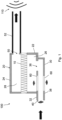
- FIG. 1 illustrates in a cut view an embodiment of a filter system 100 according to the invention.
- the filter system 100 comprises a housing 20 for a filter element 10.
- the filter element 10 may be configured generally as a flat body having, e.g., a pleated filter medium.
- the housing comprises an inlet 40 in fluid connection with a raw side volume 26 and an outlet 50 in fluid connection with a clean side volume 28.
- the raw side volume 26 is arranged in a first housing shell 22 and the clean side volume 28 is arranged in a second housing shell 24.
- the volumes 26, 28 are separated by the filter element 10.
- the first and second housing shells 22, 24 may be detachably connected to each other so that the filter element 10 may be removed and replaced by a new filter element 10.
- a segment 30 of the first housing shell 22 constitutes an outer wall 38 of an inlet duct 32, which extends into the first housing shell 22.
- the inlet duct 32 comprises at least one acoustically effective element 60 arranged at least partially inside the housing shell 22 and, in the embodiments shown, in the outer wall 38 of the inlet duct 32, too.
- the housing is connected to a noise source 110, e.g. an engine, by an outlet tube 52.
- a noise source 110 e.g. an engine
- the fluid flow from the inlet duct 32 to the outlet duct 52 is indicated by bold arrows.
- the noise from the noise source 110 travels from the outlet duct 52 through the filter element 100 to the inlet duct 32.
- the acoustically effective element 60 is a damper element made of a porous material and being configured to emit acoustic noise coming from a noise source 110, such as an engine, through the clean side volume 28 at least into the raw side volume 26.
- the acoustically effective element 60 may be made of a plastic material.
- the inlet duct 32 is directly acoustically coupled to the raw side volume 26 and can effectively reduce the noise coming from source 110.
- the inlet duct 32 is in fluid connection with the raw side volume 26 through an orifice 36.
- the outer wall 38 of the inlet duct 32 and the first housing shell 22 may be composed of the same material.
- the outer wall 38 of the inlet duct 32 and the first housing shell 22 are composed of different materials.
- the outer wall 38 may consist of a material 34.
- the inlet duct 32 extends with a tube section 42 from the first housing shell 22. This allows to attach the inlet duct 32 to a remote fluid source (not shown).
- the tube section 42 may comprise a material 44 different from the first housing shell 22 and from the outer wall 38 of the inlet duct 32.
- the housing 20 can be easily attached to other parts in the mounting area of the filter system 100.
Landscapes
- Engineering & Computer Science (AREA)
- Chemical & Material Sciences (AREA)
- Chemical Kinetics & Catalysis (AREA)
- Combustion & Propulsion (AREA)
- Mechanical Engineering (AREA)
- General Engineering & Computer Science (AREA)
- Manufacturing & Machinery (AREA)
- Filtering Of Dispersed Particles In Gases (AREA)
Description
- The invention relates to a housing for a filter element and a filter system comprising a housing, in particular to a filter system comprising a noise reducing component.
- In
DE102007039048A1 an air cleaner is disclosed, having an inlet air channel comprising an acoustic channel section with air-tight barrier areas and with a porous damping barrier segment. The acoustic channel section is an extruded plastic tube. The porous damping barrier segment is in-extruded between the air-tight barrier areas. - From
DE 1 02004013654A1 an air intake device is known, having an intake air section with an air intake duct connected to an intake for ambient air, which serves as intake air path to an engine body. A permeable aperture has an opening located within part of the air section, to connect the section to its environment, and a porous element to cover the opening. - At
DE10331950A1 a device is published having a tubular intake pipe with intake for ambient air, an air filter downstream in the intake pipe, and an air filter hose downstream of the filter, connected to a combustion chamber of an engine. Several transmission apertures closed by air-permeable elements are located in two of the components, e.g. intake pipe, filter, or hose. -
DE 202006012659U1 shows an air filter system for an internal combustion engine wherein a filter chamber is provided in the air filter housing to accommodate the filter element, whereby the filter chamber communicates with an inflow channel on the raw air side and with an outflow channel on the clean air side. The housing wall of the air filter housing at least one additional opening connected to the filter chamber, which is covered by an air-permeable, porous cover layer. -
DE102004043335A1 displays a noise configuration device for use in motor vehicle, having an air duct provided in area within which highest acoustic pressure is present in proximity to resonant frequency of air duct which is locked with noise absorbing material. - In
EP2138700A2 a filter housing can be found including two housing shells manufactured from plastic and a filter element separates a dirty side chamber from a clean side chamber. The filter housing having a loudspeaker membrane, an electromagnetic actuator and a loudspeaker housing for accommodating the actuator. - An air cleaner is presented in
US20160325218A1 including a hollow case, a filter element, and an opening end member. The hollow case defines an expanded space; the filter element defines an upstream-side expanded space and a downstream-side expanded space in the expanded space; the opening end member is formed from a material having an air permeability. - It is an object of the invention to provide a housing for a filter element with improved acoustic properties.
- It is another object of the invention to provide a filter system comprising a housing with improved acoustic properties.
- One object is achieved by a housing for a filter element, in particular for an air cleaner, in particular for a combustion engine or for a fuel cell application, having an inlet in fluid connection with a raw side volume and an outlet in fluid connection with a clean side volume, the raw side volume being arranged in a first housing shell and the clean side volume being arranged in a second housing shell, the volumes being configured to be separated by the filter element when mounted in the housing. A segment of the first housing shell constitutes an outer wall of an inlet duct, the inlet duct extending into the first housing shell, the inlet duct comprising at least one acoustically effective element arranged at least partially inside the housing shell and being configured to emit acoustic noise coming through the clean side volume at least into the raw side volume.
- Another object is achieved by a filter system, in particular for an air cleaner, in particular for a combustion engine or for a fuel cell application, comprising a housing, wherein a filter element, in particular an exchangeable filter element, is accommodated in the housing, the housing having an inlet in fluid connection with a raw side volume and an outlet in fluid connection with a clean side volume, the raw side volume being arranged in a first housing shell and the clean side volume being arranged in a second housing shell, the volumes being configured to be separated by the filter element when mounted in the housing, wherein a segment of the first housing shell constitutes an outer wall of an inlet duct, the inlet duct extending into the first housing shell, the inlet duct comprising at least one acoustically effective portion arranged at least partially inside the housing shell and being configured to emit acoustic noise coming through the clean side volume at least into the raw side volume.
- Advantageous embodiments of the invention are described in the dependent claims, the description and the drawings.
- According to an aspect of the invention, a housing for a filter element is proposed, in particular for an air cleaner, in particular for a combustion engine or for a fuel cell application, having an inlet in fluid connection with a raw side volume and an outlet in fluid connection with a clean side volume, the raw side volume being arranged in a first housing shell and the clean side volume being arranged in a second housing shell, the volumes being configured to be separated by the filter element when mounted in the housing. A segment of the first housing shell constitutes an outer wall of an inlet duct, the inlet duct extending into the first housing shell, the inlet duct comprising at least one acoustically effective element arranged at least partially inside the housing shell and being configured to emit acoustic noise coming through the clean side volume at least into the raw side volume.
- By integrating the inlet duct into the housing it is possible to create a favorable acoustic communication between the inlet duct and the housing of the filter system via the at least one acoustically effective element.
- Advantageously, the acoustic efficiency can be increased as well as a cost efficient housing provided.
- According to the invention, at least one acoustically effective element is a damper element in the type of a porous medium. One or more patches of the porous medium may be arranged in the wall of the inlet duct. For instance in an air cleaner of a combustion engine or a fuel cell application, the engine or fuel cell noise level can be reduced with the at least one acoustically effective element and the acoustic connection with the housing. In particular, the first housing shell accommodating the raw side volume and the inlet duct may be the same part.
- The porous damping element may be made of a plastic material part, particularly from materials such as polyethylene (PE), polypropylene (PP) or polyamide (PA) or mixtures therefrom.
- The acoustically effective element is be arranged in the outer wall of the inlet duct. The acoustic efficiency can be increased further.
- According to the invention, the inlet duct is in fluid connection with the raw side volume through an orifice. In particular the orifice may have a larger cross section than the inlet. The arrangement can be optimized for the fabrication process, such as injection molding. According to a favorable embodiment of the housing, the outer wall of the inlet duct and the first housing shell may be composed of the same material. In particular, the housing may be made of plastic material.
- According to a favorable embodiment of the housing, the outer wall of the inlet duct and the first housing shell may be composed of different materials. In particular, the housing and the outer wall of the inlet duct may be made of different plastic materials. Advantageously, this allows for applications where the inlet duct has a crooked shape, in particular due to limited mounting space for the housing or other packaging requirements, e.g. in an automotive ambient.
- The inlet duct extends with a tube section from the first housing shell. Favorably, the housing with the integrated inlet duct can be adapted to mounting and space requirements for the housing.
- According to a favorable embodiment of the housing, the tube section may comprise a material different from the first housing shell and/or from the outer wall of the inlet duct. Favorably, the housing with the integrated inlet duct can be adapted to mounting and space requirements for the housing.
- According to another aspect of the invention, a filter system is proposed, in particular for an air cleaner, in particular for a combustion engine or for a fuel cell application, comprising a housing, wherein a filter element, in particular an exchangeable filter element, is accommodated in the housing, the housing having an inlet in fluid connection with a raw side volume and an outlet in fluid connection with a clean side volume, the raw side volume being arranged in a first housing shell and the clean side volume being arranged in a second housing shell, the volumes being configured to be separated by the filter element when mounted in the housing, wherein a segment of the first housing shell constitutes an outer wall of an inlet duct, the inlet duct extending into the first housing shell, the inlet duct comprising at least one acoustically effective portion arranged at least partially inside the housing shell and being configured to emit acoustic noise coming through the clean side volume at least into the raw side volume.
- By integrating the inlet duct into the housing of the filter system it is possible to create a favorable acoustic communication between the inlet duct and the housing of the filter system via the at least one acoustically effective element.
- Advantageously, the acoustic efficiency of the filter system can be increased as well as a cost efficient housing provided.
- At least one acoustically effective element is arranged in the outer wall of the inlet duct. The acoustical efficiency can be improved further.
- The inlet is in fluid connection with the raw side volume through an orifice. In particular the orifice may have a larger cross section than the inlet. The arrangement of the filter system can be optimized for the fabrication process of the housing, such as injection molding.
- According to a favorable embodiment of the filter system, the outer wall of the inlet duct and the first housing shell may be composed of the same material. In an alternative embodiment the outer wall of the inlet duct and the first housing shell may be composed of different materials. The housing of the filter system can easily be adapted to packaging and process requirements.
- The inlet duct extends with a tube section from the first housing shell. The housing of the filter system can easily be adapted to packaging and mounting space requirements.
- According to a favorable embodiment of the filter system, the tube section may comprise a material different from the first housing shell and/or from the outer wall of the inlet duct. The construction of the housing of the filter system can easily be adapted to packaging and process requirements.
- The present invention together with the above-mentioned and other objects and advantages may best be understood from the following detailed description of the embodiments, but not restricted to the embodiments, wherein is shown in:
-
Figure 1 in a cut view an embodiment of a filter system according to the invention; -
Figure 2 in a cut view a further embodiment of a filter system according to the invention; -
Figure 3 in a cut view a further embodiment of a filter system according to the invention; -
Figure 4 in a cut view a further embodiment of a filter system according to the invention. - In the drawings, like elements are referred to with equal reference numerals. The drawings are merely schematic representations, not intended to portray specific parameters of the invention. Moreover, the drawings are intended to depict only typical embodiments of the invention and therefore should not be considered as limiting the scope of the invention.
- For instance, the
filter system 100 described in the Figures may be used as an air cleaner, in particular for a combustion engine or for a fuel cell application. -
Figure 1 illustrates in a cut view an embodiment of afilter system 100 according to the invention. Thefilter system 100 comprises ahousing 20 for afilter element 10. Thefilter element 10 may be configured generally as a flat body having, e.g., a pleated filter medium. - As can be seen in
Figures 1-4 , the housing comprises aninlet 40 in fluid connection with araw side volume 26 and anoutlet 50 in fluid connection with aclean side volume 28. Theraw side volume 26 is arranged in afirst housing shell 22 and theclean side volume 28 is arranged in asecond housing shell 24. Thevolumes filter element 10. The first andsecond housing shells filter element 10 may be removed and replaced by anew filter element 10. - A
segment 30 of thefirst housing shell 22 constitutes anouter wall 38 of aninlet duct 32, which extends into thefirst housing shell 22. Theinlet duct 32 comprises at least one acousticallyeffective element 60 arranged at least partially inside thehousing shell 22 and, in the embodiments shown, in theouter wall 38 of theinlet duct 32, too. - The housing is connected to a
noise source 110, e.g. an engine, by anoutlet tube 52. The fluid flow from theinlet duct 32 to theoutlet duct 52 is indicated by bold arrows. The noise from thenoise source 110 travels from theoutlet duct 52 through thefilter element 100 to theinlet duct 32. - The acoustically
effective element 60 is a damper element made of a porous material and being configured to emit acoustic noise coming from anoise source 110, such as an engine, through theclean side volume 28 at least into theraw side volume 26. The acousticallyeffective element 60 may be made of a plastic material. - The
inlet duct 32 is directly acoustically coupled to theraw side volume 26 and can effectively reduce the noise coming fromsource 110. - The
inlet duct 32 is in fluid connection with theraw side volume 26 through anorifice 36. As can be seen inFigure 1 , theouter wall 38 of theinlet duct 32 and thefirst housing shell 22 may be composed of the same material. - As can be seen in
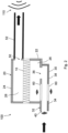
Figure 2 , theouter wall 38 of theinlet duct 32 and thefirst housing shell 22 are composed of different materials. Theouter wall 38 may consist of amaterial 34. - As can be seen in
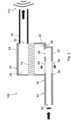
Figure 3 , theinlet duct 32 extends with atube section 42 from thefirst housing shell 22. This allows to attach theinlet duct 32 to a remote fluid source (not shown). - As can be seen in
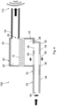
Figure 4 , thetube section 42 may comprise a material 44 different from thefirst housing shell 22 and from theouter wall 38 of theinlet duct 32. Thehousing 20 can be easily attached to other parts in the mounting area of thefilter system 100. -
- 10
- filter element
- 12
- filter medium
- 20
- housing
- 22
- first housing shell
- 24
- second housing shell
- 26
- raw side volume
- 28
- clean side volume
- 30
- shell segment
- 32
- inlet duct
- 34
- material
- 36
- orifice
- 38
- outer wall
- 40
- inlet
- 42
- tube section
- 44
- material
- 50
- outlet
- 52
- outlet duct
- 60
- acoustically effective portion
- 100
- filter system
Claims (10)
- A housing (20) for a filter element (10), in particular for an air cleaner,having an inlet (40) in fluid connection with a raw side volume (26) and an outlet (50) in fluid connection with a clean side volume (28),the raw side volume (26) being arranged in a first housing shell (22) and the clean side volume (28) being arranged in a second housing shell (24),the volumes (26, 28) being configured to be separated by the filter element (10) when mounted in the housing (20),wherein a segment (30) of the first housing shell (22) constitutes an outer wall (38) of an inlet duct (32), the inlet duct (32) extending into the first housing shell (22),the inlet duct (32) comprising at least one damper element (60) in the type of a porous medium as acoustically effective element (60) arranged at least partially inside the housing shell (22) and being configured to emit acoustic noise coming through the clean side volume (28) at least into the raw side volume (26), wherein the at least one damper element (60) is arranged in the outer wall (38) of the inlet duct (32) and an outer wall (38) of the first housing shell (22), wherein the inlet duct (32) is in fluid connection with the raw side volume (26) through an orifice (36), wherein the inlet duct (32) extends with a tube section (42) from the first housing shell (22).
- The housing according to claim 1, wherein the orifice (36) has a larger cross section than the inlet (40).
- The housing according to any one of the claims 1 or 2, wherein the outer wall (38) of the inlet duct (32) and the first housing shell (22) are composed of the same material.
- The housing according to any one of the claims 1 to 3, wherein the outer wall (38) of the inlet duct (32) and the first housing shell (22) are composed of different materials.
- The housing according to claim 4, wherein the tube section (42) comprises a material different from the first housing shell (22) and/or from the outer wall (38) of the inlet duct (32).
- A filter system (100), in particular for an air cleaner, comprising a housing (20), according to any one of the preceding claims, wherein a filter element (10), in particular an exchangeable filter element (10), is accommodated in the housing (20), the housing (20) having an inlet (40) in fluid connection with a raw side volume (26) and an outlet (50) in fluid connection with a clean side volume (28),the raw side volume (26) being arranged in a first housing shell (22) and the clean side volume (28) being arranged in a second housing shell (24),the volumes (26, 28) being configured to be separated by the filter element (10) when mounted in the housing (20),wherein a segment (30) of the first housing shell (22) constitutes an outer wall (38) of an inlet duct (32), the inlet duct (32) extending into the first housing shell (22),the inlet duct (32) comprising one damper element in the type of a porous medium as an acoustically effective portion (60) arranged at least partially inside the housing shell (22) and being configured to emit acoustic noise coming through the clean side volume (28) at least into the raw side volume (26).
- The filter system according to claim claim 6, wherein the orifice (36) has a larger cross section than the inlet (40).
- The filter system according to any one of the claims 6 to 7, wherein the outer wall (38) of the inlet duct (32) and the first housing shell (22) are composed of the same material.
- The filter system according to any one of the claims 6 to 7, wherein the outer wall (38) of the inlet duct (32) and the first housing shell (22) are composed of different materials.
- The filter system according to claims 6-9, wherein the tube section (42) comprises a material different from the first housing shell (22) and/or from the outer wall (38) of the inlet duct (32).
Priority Applications (1)
| Application Number | Priority Date | Filing Date | Title |
|---|---|---|---|
| EP22305203.6A EP4234065B1 (en) | 2022-02-24 | 2022-02-24 | Housing for a filter element and filter system comprising a housing |
Applications Claiming Priority (1)
| Application Number | Priority Date | Filing Date | Title |
|---|---|---|---|
| EP22305203.6A EP4234065B1 (en) | 2022-02-24 | 2022-02-24 | Housing for a filter element and filter system comprising a housing |
Publications (2)
| Publication Number | Publication Date |
|---|---|
| EP4234065A1 EP4234065A1 (en) | 2023-08-30 |
| EP4234065B1 true EP4234065B1 (en) | 2025-04-02 |
Family
ID=80683742
Family Applications (1)
| Application Number | Title | Priority Date | Filing Date |
|---|---|---|---|
| EP22305203.6A Active EP4234065B1 (en) | 2022-02-24 | 2022-02-24 | Housing for a filter element and filter system comprising a housing |
Country Status (1)
| Country | Link |
|---|---|
| EP (1) | EP4234065B1 (en) |
Family Cites Families (7)
| Publication number | Priority date | Publication date | Assignee | Title |
|---|---|---|---|---|
| DE10331950B9 (en) * | 2002-07-16 | 2008-03-27 | Toyoda Gosei Co., Ltd., Haruhi | intake device |
| JP2004285895A (en) * | 2003-03-20 | 2004-10-14 | Toyoda Gosei Co Ltd | Intake device |
| DE102004043335A1 (en) * | 2004-09-08 | 2006-03-09 | Daimlerchrysler Ag | Noise configuration device for use in motor vehicle, has air duct provided in area within which highest acoustic pressure is present in proximity to resonant frequency of air duct which is locked with noise absorbing material |
| DE202006012659U1 (en) * | 2006-08-17 | 2007-12-27 | Mann + Hummel Gmbh | Air filter system for an internal combustion engine |
| DE102007039048A1 (en) | 2007-08-17 | 2009-02-19 | Mann + Hummel Gmbh | Inlet air channel, particularly for internal-combustion engine of motor vehicle, has acoustic channel section is extruded plastic tube and porous damping barrier segment is in-extruded between air-tight barrier areas |
| DE102008030197A1 (en) * | 2008-06-25 | 2009-12-31 | Mahle International Gmbh | Air filter and thus equipped fresh air system |
| JP6452540B2 (en) * | 2015-05-07 | 2019-01-16 | タイガースポリマー株式会社 | Air cleaner |
-
2022
- 2022-02-24 EP EP22305203.6A patent/EP4234065B1/en active Active
Also Published As
| Publication number | Publication date |
|---|---|
| EP4234065A1 (en) | 2023-08-30 |
Similar Documents
| Publication | Publication Date | Title |
|---|---|---|
| CN102644531B (en) | Resonant system | |
| US5106397A (en) | Air cleaner/noise silencer assembly | |
| JP4514235B2 (en) | Filter element | |
| US6881237B2 (en) | Air filter for an internal combustion engine | |
| US8381871B1 (en) | Compact low frequency resonator | |
| US8485153B2 (en) | Air intake apparatus | |
| US7249652B2 (en) | Fluid guideline, especially in the form of a tube for taking up untreated air in an air filter of a motor vehicle | |
| CN105673277B (en) | Air cleaner assembly with integrated acoustic resonator | |
| US7658263B2 (en) | Device for noise transmission in a motor vehicle | |
| US20160097315A1 (en) | Silencer | |
| JP6767711B2 (en) | Silencer and ejector using silencer | |
| US20080264719A1 (en) | Silencer | |
| CN109982768B (en) | Air filter with fluted media and free standing preform shell | |
| JP2016217147A (en) | Resonator and air duct with resonator | |
| US20040226772A1 (en) | Air intake apparatus | |
| US7000583B2 (en) | Intake apparatus | |
| CN106110787A (en) | Air filter | |
| EP4234065B1 (en) | Housing for a filter element and filter system comprising a housing | |
| JP2004346750A (en) | Composite type duct | |
| CN111140414A (en) | Resonator with excellent sealing performance | |
| US20240075419A1 (en) | Filter Element for a Filter System Having a Resonator Structure, and Filter System Having a Resonator Structure | |
| JP2010002147A (en) | Ventilating duct | |
| EP3339623B1 (en) | Air cleaner for internal combustion engine | |
| JP2001132567A (en) | Intake device | |
| JP4320496B2 (en) | Air duct module |
Legal Events
| Date | Code | Title | Description |
|---|---|---|---|
| PUAI | Public reference made under article 153(3) epc to a published international application that has entered the european phase |
Free format text: ORIGINAL CODE: 0009012 |
|
| STAA | Information on the status of an ep patent application or granted ep patent |
Free format text: STATUS: THE APPLICATION HAS BEEN PUBLISHED |
|
| AK | Designated contracting states |
Kind code of ref document: A1 Designated state(s): AL AT BE BG CH CY CZ DE DK EE ES FI FR GB GR HR HU IE IS IT LI LT LU LV MC MK MT NL NO PL PT RO RS SE SI SK SM TR |
|
| STAA | Information on the status of an ep patent application or granted ep patent |
Free format text: STATUS: REQUEST FOR EXAMINATION WAS MADE |
|
| 17P | Request for examination filed |
Effective date: 20240228 |
|
| RBV | Designated contracting states (corrected) |
Designated state(s): AL AT BE BG CH CY CZ DE DK EE ES FI FR GB GR HR HU IE IS IT LI LT LU LV MC MK MT NL NO PL PT RO RS SE SI SK SM TR |
|
| STAA | Information on the status of an ep patent application or granted ep patent |
Free format text: STATUS: EXAMINATION IS IN PROGRESS |
|
| 17Q | First examination report despatched |
Effective date: 20240507 |
|
| GRAP | Despatch of communication of intention to grant a patent |
Free format text: ORIGINAL CODE: EPIDOSNIGR1 |
|
| STAA | Information on the status of an ep patent application or granted ep patent |
Free format text: STATUS: GRANT OF PATENT IS INTENDED |
|
| INTG | Intention to grant announced |
Effective date: 20240924 |
|
| GRAS | Grant fee paid |
Free format text: ORIGINAL CODE: EPIDOSNIGR3 |
|
| RIN1 | Information on inventor provided before grant (corrected) |
Inventor name: LAUNAY, TRISTAN Inventor name: FOULBOEUF, GWENAEL Inventor name: WARNERY, STEPHANE |
|
| GRAA | (expected) grant |
Free format text: ORIGINAL CODE: 0009210 |
|
| STAA | Information on the status of an ep patent application or granted ep patent |
Free format text: STATUS: THE PATENT HAS BEEN GRANTED |
|
| AK | Designated contracting states |
Kind code of ref document: B1 Designated state(s): AL AT BE BG CH CY CZ DE DK EE ES FI FR GB GR HR HU IE IS IT LI LT LU LV MC MK MT NL NO PL PT RO RS SE SI SK SM TR |
|
| REG | Reference to a national code |
Ref country code: GB Ref legal event code: FG4D |
|
| REG | Reference to a national code |
Ref country code: CH Ref legal event code: EP |
|
| REG | Reference to a national code |
Ref country code: DE Ref legal event code: R096 Ref document number: 602022012542 Country of ref document: DE |
|
| REG | Reference to a national code |
Ref country code: IE Ref legal event code: FG4D |
|
| P01 | Opt-out of the competence of the unified patent court (upc) registered |
Free format text: CASE NUMBER: APP_31643/2025 Effective date: 20250701 |
|
| REG | Reference to a national code |
Ref country code: NL Ref legal event code: MP Effective date: 20250402 |
|
| PG25 | Lapsed in a contracting state [announced via postgrant information from national office to epo] |
Ref country code: NL Free format text: LAPSE BECAUSE OF FAILURE TO SUBMIT A TRANSLATION OF THE DESCRIPTION OR TO PAY THE FEE WITHIN THE PRESCRIBED TIME-LIMIT Effective date: 20250402 |
|
| REG | Reference to a national code |
Ref country code: AT Ref legal event code: MK05 Ref document number: 1780743 Country of ref document: AT Kind code of ref document: T Effective date: 20250402 |
|
| PG25 | Lapsed in a contracting state [announced via postgrant information from national office to epo] |
Ref country code: FI Free format text: LAPSE BECAUSE OF FAILURE TO SUBMIT A TRANSLATION OF THE DESCRIPTION OR TO PAY THE FEE WITHIN THE PRESCRIBED TIME-LIMIT Effective date: 20250402 Ref country code: PT Free format text: LAPSE BECAUSE OF FAILURE TO SUBMIT A TRANSLATION OF THE DESCRIPTION OR TO PAY THE FEE WITHIN THE PRESCRIBED TIME-LIMIT Effective date: 20250804 Ref country code: ES Free format text: LAPSE BECAUSE OF FAILURE TO SUBMIT A TRANSLATION OF THE DESCRIPTION OR TO PAY THE FEE WITHIN THE PRESCRIBED TIME-LIMIT Effective date: 20250402 |
|
| REG | Reference to a national code |
Ref country code: LT Ref legal event code: MG9D |
|
| PG25 | Lapsed in a contracting state [announced via postgrant information from national office to epo] |
Ref country code: GR Free format text: LAPSE BECAUSE OF FAILURE TO SUBMIT A TRANSLATION OF THE DESCRIPTION OR TO PAY THE FEE WITHIN THE PRESCRIBED TIME-LIMIT Effective date: 20250703 Ref country code: NO Free format text: LAPSE BECAUSE OF FAILURE TO SUBMIT A TRANSLATION OF THE DESCRIPTION OR TO PAY THE FEE WITHIN THE PRESCRIBED TIME-LIMIT Effective date: 20250702 |
|
| PG25 | Lapsed in a contracting state [announced via postgrant information from national office to epo] |
Ref country code: PL Free format text: LAPSE BECAUSE OF FAILURE TO SUBMIT A TRANSLATION OF THE DESCRIPTION OR TO PAY THE FEE WITHIN THE PRESCRIBED TIME-LIMIT Effective date: 20250402 |
|
| PG25 | Lapsed in a contracting state [announced via postgrant information from national office to epo] |
Ref country code: BG Free format text: LAPSE BECAUSE OF FAILURE TO SUBMIT A TRANSLATION OF THE DESCRIPTION OR TO PAY THE FEE WITHIN THE PRESCRIBED TIME-LIMIT Effective date: 20250402 |
|
| PG25 | Lapsed in a contracting state [announced via postgrant information from national office to epo] |
Ref country code: HR Free format text: LAPSE BECAUSE OF FAILURE TO SUBMIT A TRANSLATION OF THE DESCRIPTION OR TO PAY THE FEE WITHIN THE PRESCRIBED TIME-LIMIT Effective date: 20250402 |
|
| PG25 | Lapsed in a contracting state [announced via postgrant information from national office to epo] |
Ref country code: AT Free format text: LAPSE BECAUSE OF FAILURE TO SUBMIT A TRANSLATION OF THE DESCRIPTION OR TO PAY THE FEE WITHIN THE PRESCRIBED TIME-LIMIT Effective date: 20250402 |
|
| PG25 | Lapsed in a contracting state [announced via postgrant information from national office to epo] |
Ref country code: RS Free format text: LAPSE BECAUSE OF FAILURE TO SUBMIT A TRANSLATION OF THE DESCRIPTION OR TO PAY THE FEE WITHIN THE PRESCRIBED TIME-LIMIT Effective date: 20250702 |
|
| PG25 | Lapsed in a contracting state [announced via postgrant information from national office to epo] |
Ref country code: IS Free format text: LAPSE BECAUSE OF FAILURE TO SUBMIT A TRANSLATION OF THE DESCRIPTION OR TO PAY THE FEE WITHIN THE PRESCRIBED TIME-LIMIT Effective date: 20250802 |
|
| PG25 | Lapsed in a contracting state [announced via postgrant information from national office to epo] |
Ref country code: LV Free format text: LAPSE BECAUSE OF FAILURE TO SUBMIT A TRANSLATION OF THE DESCRIPTION OR TO PAY THE FEE WITHIN THE PRESCRIBED TIME-LIMIT Effective date: 20250402 |
|
| PG25 | Lapsed in a contracting state [announced via postgrant information from national office to epo] |
Ref country code: DK Free format text: LAPSE BECAUSE OF FAILURE TO SUBMIT A TRANSLATION OF THE DESCRIPTION OR TO PAY THE FEE WITHIN THE PRESCRIBED TIME-LIMIT Effective date: 20250402 Ref country code: SM Free format text: LAPSE BECAUSE OF FAILURE TO SUBMIT A TRANSLATION OF THE DESCRIPTION OR TO PAY THE FEE WITHIN THE PRESCRIBED TIME-LIMIT Effective date: 20250402 |
|
| PG25 | Lapsed in a contracting state [announced via postgrant information from national office to epo] |
Ref country code: CZ Free format text: LAPSE BECAUSE OF FAILURE TO SUBMIT A TRANSLATION OF THE DESCRIPTION OR TO PAY THE FEE WITHIN THE PRESCRIBED TIME-LIMIT Effective date: 20250402 |
|
| PG25 | Lapsed in a contracting state [announced via postgrant information from national office to epo] |
Ref country code: EE Free format text: LAPSE BECAUSE OF FAILURE TO SUBMIT A TRANSLATION OF THE DESCRIPTION OR TO PAY THE FEE WITHIN THE PRESCRIBED TIME-LIMIT Effective date: 20250402 |
|
| PG25 | Lapsed in a contracting state [announced via postgrant information from national office to epo] |
Ref country code: SK Free format text: LAPSE BECAUSE OF FAILURE TO SUBMIT A TRANSLATION OF THE DESCRIPTION OR TO PAY THE FEE WITHIN THE PRESCRIBED TIME-LIMIT Effective date: 20250402 |
|
| PG25 | Lapsed in a contracting state [announced via postgrant information from national office to epo] |
Ref country code: IT Free format text: LAPSE BECAUSE OF FAILURE TO SUBMIT A TRANSLATION OF THE DESCRIPTION OR TO PAY THE FEE WITHIN THE PRESCRIBED TIME-LIMIT Effective date: 20250402 |
|
| PLBE | No opposition filed within time limit |
Free format text: ORIGINAL CODE: 0009261 |
|
| STAA | Information on the status of an ep patent application or granted ep patent |
Free format text: STATUS: NO OPPOSITION FILED WITHIN TIME LIMIT |
|
| REG | Reference to a national code |
Ref country code: CH Ref legal event code: L10 Free format text: ST27 STATUS EVENT CODE: U-0-0-L10-L00 (AS PROVIDED BY THE NATIONAL OFFICE) Effective date: 20260211 |