EP4233810A1 - Device for treating eye tissue using a pulsed charger beam - Google Patents
Device for treating eye tissue using a pulsed charger beam Download PDFInfo
- Publication number
- EP4233810A1 EP4233810A1 EP23176617.1A EP23176617A EP4233810A1 EP 4233810 A1 EP4233810 A1 EP 4233810A1 EP 23176617 A EP23176617 A EP 23176617A EP 4233810 A1 EP4233810 A1 EP 4233810A1
- Authority
- EP
- European Patent Office
- Prior art keywords
- processing
- tissue
- laser beam
- pulsed laser
- paths
- Prior art date
- Legal status (The legal status is an assumption and is not a legal conclusion. Google has not performed a legal analysis and makes no representation as to the accuracy of the status listed.)
- Granted
Links
- 238000012545 processing Methods 0.000 claims abstract description 271
- 238000005520 cutting process Methods 0.000 claims abstract description 88
- 238000003754 machining Methods 0.000 claims description 27
- 210000004087 cornea Anatomy 0.000 claims description 17
- 239000004744 fabric Substances 0.000 claims description 2
- 230000003287 optical effect Effects 0.000 description 46
- 241000219739 Lens Species 0.000 description 11
- 230000008859 change Effects 0.000 description 11
- 238000013461 design Methods 0.000 description 11
- 230000002093 peripheral effect Effects 0.000 description 11
- 238000011144 upstream manufacturing Methods 0.000 description 10
- 230000005540 biological transmission Effects 0.000 description 9
- 238000005259 measurement Methods 0.000 description 9
- 238000000034 method Methods 0.000 description 6
- 230000006978 adaptation Effects 0.000 description 5
- 230000001419 dependent effect Effects 0.000 description 5
- 230000004075 alteration Effects 0.000 description 4
- 206010020675 Hypermetropia Diseases 0.000 description 3
- 238000001514 detection method Methods 0.000 description 3
- 230000006870 function Effects 0.000 description 3
- 230000001360 synchronised effect Effects 0.000 description 3
- 240000004322 Lens culinaris Species 0.000 description 2
- 230000008901 benefit Effects 0.000 description 2
- 238000012937 correction Methods 0.000 description 2
- 238000010586 diagram Methods 0.000 description 2
- 201000006318 hyperopia Diseases 0.000 description 2
- 230000004305 hyperopia Effects 0.000 description 2
- 230000008569 process Effects 0.000 description 2
- 230000015572 biosynthetic process Effects 0.000 description 1
- 230000007423 decrease Effects 0.000 description 1
- 238000006073 displacement reaction Methods 0.000 description 1
- 239000012530 fluid Substances 0.000 description 1
- 238000003384 imaging method Methods 0.000 description 1
- 230000006872 improvement Effects 0.000 description 1
- 238000004519 manufacturing process Methods 0.000 description 1
- 230000015654 memory Effects 0.000 description 1
- 230000000737 periodic effect Effects 0.000 description 1
- 238000013519 translation Methods 0.000 description 1
Images


Classifications
-
- A—HUMAN NECESSITIES
- A61—MEDICAL OR VETERINARY SCIENCE; HYGIENE
- A61F—FILTERS IMPLANTABLE INTO BLOOD VESSELS; PROSTHESES; DEVICES PROVIDING PATENCY TO, OR PREVENTING COLLAPSING OF, TUBULAR STRUCTURES OF THE BODY, e.g. STENTS; ORTHOPAEDIC, NURSING OR CONTRACEPTIVE DEVICES; FOMENTATION; TREATMENT OR PROTECTION OF EYES OR EARS; BANDAGES, DRESSINGS OR ABSORBENT PADS; FIRST-AID KITS
- A61F9/00—Methods or devices for treatment of the eyes; Devices for putting-in contact lenses; Devices to correct squinting; Apparatus to guide the blind; Protective devices for the eyes, carried on the body or in the hand
- A61F9/007—Methods or devices for eye surgery
- A61F9/008—Methods or devices for eye surgery using laser
- A61F9/00825—Methods or devices for eye surgery using laser for photodisruption
- A61F9/0084—Laser features or special beam parameters therefor
-
- A—HUMAN NECESSITIES
- A61—MEDICAL OR VETERINARY SCIENCE; HYGIENE
- A61F—FILTERS IMPLANTABLE INTO BLOOD VESSELS; PROSTHESES; DEVICES PROVIDING PATENCY TO, OR PREVENTING COLLAPSING OF, TUBULAR STRUCTURES OF THE BODY, e.g. STENTS; ORTHOPAEDIC, NURSING OR CONTRACEPTIVE DEVICES; FOMENTATION; TREATMENT OR PROTECTION OF EYES OR EARS; BANDAGES, DRESSINGS OR ABSORBENT PADS; FIRST-AID KITS
- A61F9/00—Methods or devices for treatment of the eyes; Devices for putting-in contact lenses; Devices to correct squinting; Apparatus to guide the blind; Protective devices for the eyes, carried on the body or in the hand
- A61F9/007—Methods or devices for eye surgery
- A61F9/008—Methods or devices for eye surgery using laser
- A61F9/00825—Methods or devices for eye surgery using laser for photodisruption
- A61F9/00827—Refractive correction, e.g. lenticle
-
- A—HUMAN NECESSITIES
- A61—MEDICAL OR VETERINARY SCIENCE; HYGIENE
- A61F—FILTERS IMPLANTABLE INTO BLOOD VESSELS; PROSTHESES; DEVICES PROVIDING PATENCY TO, OR PREVENTING COLLAPSING OF, TUBULAR STRUCTURES OF THE BODY, e.g. STENTS; ORTHOPAEDIC, NURSING OR CONTRACEPTIVE DEVICES; FOMENTATION; TREATMENT OR PROTECTION OF EYES OR EARS; BANDAGES, DRESSINGS OR ABSORBENT PADS; FIRST-AID KITS
- A61F9/00—Methods or devices for treatment of the eyes; Devices for putting-in contact lenses; Devices to correct squinting; Apparatus to guide the blind; Protective devices for the eyes, carried on the body or in the hand
- A61F9/007—Methods or devices for eye surgery
- A61F9/008—Methods or devices for eye surgery using laser
- A61F9/00825—Methods or devices for eye surgery using laser for photodisruption
- A61F9/00836—Flap cutting
-
- A—HUMAN NECESSITIES
- A61—MEDICAL OR VETERINARY SCIENCE; HYGIENE
- A61F—FILTERS IMPLANTABLE INTO BLOOD VESSELS; PROSTHESES; DEVICES PROVIDING PATENCY TO, OR PREVENTING COLLAPSING OF, TUBULAR STRUCTURES OF THE BODY, e.g. STENTS; ORTHOPAEDIC, NURSING OR CONTRACEPTIVE DEVICES; FOMENTATION; TREATMENT OR PROTECTION OF EYES OR EARS; BANDAGES, DRESSINGS OR ABSORBENT PADS; FIRST-AID KITS
- A61F9/00—Methods or devices for treatment of the eyes; Devices for putting-in contact lenses; Devices to correct squinting; Apparatus to guide the blind; Protective devices for the eyes, carried on the body or in the hand
- A61F9/007—Methods or devices for eye surgery
- A61F9/008—Methods or devices for eye surgery using laser
- A61F2009/00861—Methods or devices for eye surgery using laser adapted for treatment at a particular location
- A61F2009/0087—Lens
-
- A—HUMAN NECESSITIES
- A61—MEDICAL OR VETERINARY SCIENCE; HYGIENE
- A61F—FILTERS IMPLANTABLE INTO BLOOD VESSELS; PROSTHESES; DEVICES PROVIDING PATENCY TO, OR PREVENTING COLLAPSING OF, TUBULAR STRUCTURES OF THE BODY, e.g. STENTS; ORTHOPAEDIC, NURSING OR CONTRACEPTIVE DEVICES; FOMENTATION; TREATMENT OR PROTECTION OF EYES OR EARS; BANDAGES, DRESSINGS OR ABSORBENT PADS; FIRST-AID KITS
- A61F9/00—Methods or devices for treatment of the eyes; Devices for putting-in contact lenses; Devices to correct squinting; Apparatus to guide the blind; Protective devices for the eyes, carried on the body or in the hand
- A61F9/007—Methods or devices for eye surgery
- A61F9/008—Methods or devices for eye surgery using laser
- A61F2009/00861—Methods or devices for eye surgery using laser adapted for treatment at a particular location
- A61F2009/00872—Cornea
-
- A—HUMAN NECESSITIES
- A61—MEDICAL OR VETERINARY SCIENCE; HYGIENE
- A61F—FILTERS IMPLANTABLE INTO BLOOD VESSELS; PROSTHESES; DEVICES PROVIDING PATENCY TO, OR PREVENTING COLLAPSING OF, TUBULAR STRUCTURES OF THE BODY, e.g. STENTS; ORTHOPAEDIC, NURSING OR CONTRACEPTIVE DEVICES; FOMENTATION; TREATMENT OR PROTECTION OF EYES OR EARS; BANDAGES, DRESSINGS OR ABSORBENT PADS; FIRST-AID KITS
- A61F9/00—Methods or devices for treatment of the eyes; Devices for putting-in contact lenses; Devices to correct squinting; Apparatus to guide the blind; Protective devices for the eyes, carried on the body or in the hand
- A61F9/007—Methods or devices for eye surgery
- A61F9/008—Methods or devices for eye surgery using laser
- A61F2009/00897—Scanning mechanisms or algorithms
Definitions
- the present invention relates to an ophthalmological device for processing eye tissue using a pulsed laser beam.
- the present invention relates in particular to an ophthalmological device with a laser source for generating a pulsed laser beam, focusing optics for focusing the pulsed laser beam into the ocular tissue, and a scanner system for directing the pulsed laser beam to a processing target point in the ocular tissue.
- a processing area is scanned (scanned) with laser pulses by deflecting the pulsed laser beam in one or two scanning directions (scanning directions) using suitable scanner systems (deflection devices).
- the light beams or the laser pulses for example femtosecond laser pulses, are generally deflected using movable mirrors which can be pivoted about one or two scanning axes, for example using galvano scanners, piezo scanners, polygon scanners or resonance scanners.
- U.S. 7,621,637 describes a device for processing eye tissue, which has a base station with a laser source for generating laser pulses and a scanner arranged in the base station with movable deflection mirrors for deflecting the laser pulses in a scanning direction.
- the deflected laser pulses are transmitted via an optical transmission system from the base station to an application head which, by means of mechanically moved projection optics, covers a work area according to a scanning pattern.
- the deflection in the scanning direction which is much faster than the mechanical movement, is superimposed on the mechanical movement of the projection optics and thus on its scanning pattern in the application head.
- a fast scanner system in the base station enables a fine movement of the laser pulses (microscan), which is superimposed on the scanning pattern of the movable projection optics, which covers a large processing area, for example the entire eye.
- Known systems of this type allow the processing of simple scan patterns, for example the cutting of a flap of tissue (flap), which is generally designed as a large area piece with a simple edge geometry.
- tissue cuts are not only made in a substantially horizontally aligned processing area on a common focal surface, but in which cuts with a vertical cut component are also to be made over different focal heights, e.g. diagonal to the horizontal or vertical cuts vertical processes of the projection optics or a zoom system for a vertical change in the focus and thus the cutting height as too slow to perform cuts with a vertical component, i.e. with a variable focus depth during cutting, at a speed that is comparable to cutting speeds in the horizontal processing area.
- US2016/0089270 describes a system and method for cutting lenticules in ocular tissue.
- straight-line fast scan lines are superimposed on slower processing lines that are traced along meridians of the lenticle.
- the straightness of the fast scan lines results in cuts that deviate in shape from the desired surface curvature of the lenticule and therefore cause errors.
- a vertical focus shift in the order of magnitude and extent of the thickness of the lenticle to be cut is required, which on the one hand is associated with corresponding effort and costs for displaceable optics and movable lenses set up for this purpose and on the other hand with the associated losses in processing speed .
- the fast scan lines do not allow the best possible adaptation of sections to lenticle surfaces, especially not when these deviate from a spherical shape.
- an ophthalmological device for processing eye tissue comprises a laser source which is set up to generate a pulsed laser beam; focusing optics configured to focus the pulsed laser beam into the ocular tissue; and a scanner system configured to direct the pulsed laser beam to processing target points in the eye tissue; and the above objects are achieved at least in part by the circuitry being arranged to control the scanner system such that the scanner system directs the pulsed laser beam to machining target points on an in a surface to be cut on a cornea, in processing paths running next to one another, in order to first produce cutting paths, separated by remaining tissue bridges, of a tissue section to be made on the surface, and then to direct the pulsed laser beam to processing target points in the remaining tissue bridges between the cutting paths on the surface, in order to close the tissue section to complete.
- the cutting of cutting paths separated by tissue bridges enables a new cutting path to be cut at a time without being affected by deformations caused by gas formation in an already cut immediately adjacent cutting path.
- the ophthalmological device includes a measuring system that is set up to optically detect structures in the eye tissue.
- the circuit is set up to control the measurement system in such a way that the measurement system detects the generated cutting paths and positions the processing target points in the remaining tissue bridges based on the detected cutting paths.
- the measuring system is designed as an interferometric measuring system. The detection of incision paths that have already been cut and the processing of remaining tissue bridges, taking into account the incision paths that have already been cut, enables flexible adaptation to the actual shape of incision paths that have been carried out and thus avoids or at least reduces overlapping incision paths over extensive areas.
- the circuit is set up to control the scanner system in such a way that the scanner system directs the pulsed laser beam with overlapping laser pulse spots onto successive processing target points.
- the circuit is set up to control the scanner system in such a way that the scanner system directs the pulsed laser beam to processing target points in the processing paths running next to one another in the remaining tissue bridges.
- the circuit is set up to control the scanner system in such a way that the scanner system directs the pulsed laser beam in the remaining tissue bridges to processing target points in processing paths which have a width exceeding the tissue bridges.
- the circuit is set up to control the scanner system in such a way that the scanner system directs the pulsed laser beam to processing target points in processing paths running parallel next to one another.
- the circuit is set up to control the scanner system in such a way that the scanner system directs the pulsed laser beam to processing target points in processing paths running next to one another, which have a spiral, circular or elliptical shape.
- the circuit is set up to control the scanner system in such a way that the scanner system directs the pulsed laser beam in a feed direction to processing target points along a processing line running in the processing paths.
- the scanner system is set up, the pulsed laser beam along a scan line running transversely to the processing line within the To steer machining paths, with a significantly higher scanning speed compared to the scanning speed in the feed direction.
- the circuit is set up to control the scanner system in such a way that the scanner system directs the pulsed laser beam to processing target points on an outer surface of a lenticule to be cut in a cornea, in the processing paths running next to each other, in order to cut paths of the to be made, which are separated by remaining tissue bridges tissue section on the outer surface of the lenticle, and thereafter directs the pulsed laser beam to processing target points in the remaining bridges of tissue between the cutting paths on the outer surface of the lenticle to complete the tissue section.
- the circuit is set up to control the scanner system in such a way that the scanner system directs the pulsed laser beam to processing target points on the lower outer surface of the lenticule to be cut, which is remote from an outer corneal surface, in order to cut the cutting paths, separated by remaining tissue bridges, on the lower outer surface of the cutting lenticule, and that the scanner system then directs the pulsed laser beam to processing target points on an upper outer surface of the lenticle to be cut, facing the outer corneal surface, in processing paths running next to one another, in order to cut paths, separated by remaining tissue bridges, of an upper one to be carried out on the upper outer surface of the lenticle tissue section before the scanner system applies the pulsed laser beam to the processing target points in the remaining tissue bridges on the lower outer surface of the lenticle to complete the lower tissue section; and the scanner system thereafter directing the pulsed laser beam to machining target points in the remaining bridges of tissue on the upper surface of the lenticle to complete the upper tissue section.
- the ophthalmological device comprises a measuring system that is set up to optically detect structures in the eye tissue.
- the circuit is set up to control the measurement system in such a way that the measurement system detects the generated cutting paths of the lower tissue incision to be made and positions the processing paths of the upper tissue incision to be made with respect to the recorded cutting paths of the lower tissue incision.
- the measuring system is designed as an interferometric measuring system.
- the circuit is set up to determine the processing paths of the upper tissue incision to be made with reference to the detected incision paths of the lower tissue incision with a smaller path width.
- the circuit is set up to position the processing paths for completing the lower tissue incision with respect to the detected incision paths of the lower tissue incision.
- the ophthalmological device for processing ocular tissue in particular for cutting a lenticule in the ocular tissue, comprises a laser source which is set up to produce a pulsed to generate laser beam; focusing optics configured to focus the pulsed laser beam into the ocular tissue; a scanner system, comprising a first scanner module and a second scanner module, for deflecting the pulsed laser beam onto processing target points in the eye tissue; and a circuit for controlling the ophthalmic device; and the above objects are achieved at least in part by the circuit being configured to control the second scanner module such that the second scanner module directs the pulsed laser beam in a feed direction to processing target points along a processing line defined on an outer surface of an eye tissue to be cut Lenticle runs transversely to meridians of the lenticle.
- the first scanner module is set up to direct the pulsed laser beam to processing target points along a scan line running at an orientation angle transverse to the processing line in a horizontal processing plane, with a significantly higher scanning speed compared to the scanning speed of the second scanner module in the feed direction.
- the ophthalmological device includes a z-modulator that is set up to tilt the scan line from the processing plane depending on a specific processing target point of the second scanner module on the processing line such that the scan line essentially runs along the outer surface of the lenticle.
- the lenticules in the eye tissue can also be cut without vertical focus shifts in the order of magnitude and extent of the total depth of the vertical cutting component to be carried out, i.e. the thickness of the lenticule to be cut, due to shifts in the projection optics or movements of lenses of a zoom system must be carried out at a speed with which the second scanner module covers a distance of the processing line corresponding to the lateral extent of the lenticle to be cut.
- the ophthalmological device includes a rotator that is set up to rotate a fast scan plane defined by the scan line and the pulsed laser beam about an optical transmission axis in such a way that the alignment angle of the scan line to the processing line is changed.
- the circuit is set up to control the rotator depending on the specific processing target point of the second scanner module on the processing line, so that the alignment angle of the scan line to the processing line is set depending on the specific processing target point of the second scanner module on the processing line.
- the ophthalmological device includes a scan length modulator that is set up to change a length of the scan line.
- the circuit is set up to control the scan length modulator depending on the specific processing target point of the second scanner module on the processing line such that the length of the scan line is adjusted depending on the specific processing target point of the second scanner module on the processing line.
- the circuit is set up to control the second scanner module in such a way that the second scanner module directs the pulsed laser beam to processing target points in the processing plane along a circular or elliptical processing line that runs on the outer surface of the lenticle.
- the circuit is set up to control the second scanner module in such a way that the second scanner module directs the pulsed laser beam in succession along a plurality of circular or elliptical processing lines arranged in superimposed processing planes and running on the outer surface of the lenticle.
- the circuit is set up to control the second scanner module in such a way that the second scanner module directs the pulsed laser beam to processing target points along a spiral processing line that runs on the outer surface of the lenticle.
- the circuit is set up to control the second scanner module in such a way that the second scanner module directs the pulsed laser beam to processing target points along a processing line that runs in the form of a circular arc segment, a spiral arc segment or a curved line segment on the outer surface of the lenticle.
- the circuit is set up to control the second scanner module in such a way that the second scanner module directs the pulsed laser beam to processing target points along a plurality of spiral processing lines which, in a first step, proceed from a periphery of the outer surface of the lenticule in the shape of a spiral arm in the direction of a center of the Run outer surface, and run in a second step starting from the center in a spiral arm shape to the periphery of the outer surface of the lenticle.
- the circuit is set up to control the second scanner module in such a way that the second scanner module directs the pulsed laser beam to processing target points along a plurality of spiral-shaped processing lines which, in a first step, proceed from a periphery of the outer surface of the lenticule in the shape of a spiral arm in the direction of a center of the outer surface run and end at a certain distance from the center, and in a second step, starting from a certain distance from the center, run in a spiral arm to the periphery of the outer surface of the lenticle, or conversely, in the first step, starting from a certain distance from the center, run in a spiral arm to the periphery of the outer surface of the lenticle and extend from the periphery of the outer surface of the lenticule in the shape of a spiral arm towards the center of the outer surface.
- the z modulator is set up to curve the scan line with respect to the processing plane.
- the circuit is set up to control the z-modulator depending on the specific processing target point of the second scanner module on the processing line in such a way that the z-modulator curves the scan line depending on the specific processing target point of the second scanner module on the processing line for adaptation to the outer surface of the lenticle.
- the ophthalmological device includes a rotator that is set up to rotate a fast scan plane defined by the scan line and the pulsed laser beam about an optical transmission axis in order to change the alignment angle of the scan line to the processing line.
- the z modulator is set up to curve the scan line with respect to the processing plane.
- the ophthalmological device includes a scan length modulator configured to change a length of the scan line.
- the circuit is set up, depending on the specific processing target point of the second scanner module on the processing line, to control the rotator for adjusting the orientation angle of the scan line to the processing line, the z-modulator for curving the scan line with respect to the processing plane, and the scan length modulator for adjusting the length of the scan line that the outer surface of the lenticle is cut in a predetermined free form to correct a higher-order aberration.
- the ophthalmological device comprises a rotator which is set up to rotate a fast scan plane defined by the scan line and the pulsed laser beam about an optical transmission axis in order to change the orientation angle of the scan line to the processing line.
- the ophthalmic device includes a scan length modulator configured to change a length of the scan line.
- the circuit is set up, depending on the specific processing target point of the second scanner module on the processing line, to control the rotator for adjusting the alignment angle of the scan line to the processing line, the z modulator for tilting the scan line with respect to the processing plane, and the scan length modulator for adjusting the length of the scan line that the outer surface of the lenticle is cut in a predetermined free form to correct a higher-order aberration.
- the ophthalmological device for processing eye tissue comprises a laser source which is set up to generate a pulsed laser beam; focusing optics configured to focus the pulsed laser beam into the ocular tissue; and a scanner system configured to direct the pulsed laser beam to processing target points in the eye tissue; a measurement system that is set up to optically detect structures in the eye tissue; and circuitry configured to control the scanner system such that the scanner system directs the pulsed laser beam to processing target points on a first outer surface of a lenticle to be cut in the ocular tissue to create a first tissue incision for cutting the lenticle; and the above objectives are at least partially achieved in that the circuit is further set up to control the measurement system in such a way that the measurement system detects the first outer surface of the lenticle produced by the first tissue section, and to control the scanner system in such a way that the scanner system detects the pulsed laser beam to processing target points on a relation to the detected first outer surface of Lenticle positioned second
- the measuring system is designed as an interferometric measuring system.
- the detection of a tissue section on a first outer surface of a lenticle to be cut and the dependent positioning and execution of a tissue section on a second outer surface of the lenticle enables a flexible and precise adjustment of the shape and position of the tissue section to be performed or the second outer surface to the actual position and shape of the tissue section already carried out and thereby brings about an improvement in the shape and size of the lenticle, in particular its thickness, and the desired refractive correction of the eye which can thus be achieved.
- the circuit is set up to position the second outer surface of the lenticle to be cut with a predetermined center thickness of the lenticle to be cut with respect to the detected first outer surface.
- the circuit is set up to position the second outer surface of the lenticle to be cut with a predetermined thickness profile of the lenticle to be cut with respect to the detected first outer surface.
- the circuit is set up to control the measuring system in such a way that the measuring system detects deformations of the first outer surface caused by gas bubbles generated during the first tissue cut, and positions the second outer surface of the lenticule to be cut, taking into account the deformations detected with respect to the detected first outer surface.
- the circuit is set up to determine the first outer surface of the lenticle to be cut as an underside of the lenticle to be cut, facing away from an outer corneal surface, and the second outer surface of the lenticle to be cut as an upper side of the lenticle to be cut, facing from the outer corneal surface determine the lenticule.
- the circuit is set up to control the scanner system in such a way that the scanner system directs the pulsed laser beam to processing target points in processing paths running next to one another on the first outer surface of the lenticle to be cut, in order to produce cutting paths of the first tissue section running next to one another; and to control the measuring system in such a way that the measuring system detects the cutting paths running next to one another and positions the second outer surface of the lenticule to be cut with respect to the detected cutting paths running next to one another.
- the circuit is set up to control the scanner system in such a way that the scanner system directs the pulsed laser beam to processing target points in processing paths running next to one another on the first outer surface of the lenticle to be cut in order to cut paths of the first tissue section running next to one another and separated by remaining tissue bridges generate; to control the measuring system in such a way that the measuring system detects the cutting paths; and to control the scanner system in such a way that the scanner system emits the pulsed laser beam based on processing target points directs remaining tissue bridges on the first outer surface determined by the sensed incision paths to create the first tissue incision.
- the circuit is set up to control the scanner system in such a way that the scanner system directs the pulsed laser beam to processing target points in processing paths that run on the outer surface of the lenticle and are straight, running along circles, concentrically circular, concentrically elliptical, spiral-shaped or having spiral arm configuration.
- the circuit is set up to control a second scanner module of the scanner system in such a way that the second scanner module directs the pulsed laser beam to processing target points in a feed direction along a processing line that runs on the first or second outer surface of the lenticle to be cut; that the scanner system comprises a first scanner module, which is set up to steer the pulsed laser beam along a scanning line running at an orientation angle transverse to the processing line in a horizontal processing plane, with a significantly higher scanning speed compared to the scanning speed of the second scanner module in the feed direction; and that the scanner system comprises a z-modulator which is set up to tilt the scan line from the processing plane depending on a specific processing target point of the second scanner module on the processing line in such a way that the scan line essentially runs along the outer surface of the lenticle.
- reference numeral 1 refers in each case to an ophthalmological device for processing eye tissue 20 by means of laser pulses, for example the cornea or other tissue of an eye 2.
- the ophthalmological device 1 comprises a scanner system 100 for directing a pulsed laser beam L supplied by a laser source 11 via focusing optics 16 onto processing target points F in the eye tissue 20, and a measuring system 17 for the optical detection of structures in the eye tissue 20.
- the measuring system 17 is designed as an imaging measurement system, in particular as an interferometric measurement system.
- the focusing optics 16 are set up for focused projection of the pulsed laser beam L or the laser pulses for selective tissue resolution in a focus F at a processing target point inside the eye tissue 20.
- the laser beam L focused by the focusing optics 16 is denoted by the reference symbol L * .
- the focusing optics 16 are installed, for example, in an application head 160 that can be placed on the eye 2 .
- the application head 160 is preferably placed on the eye 2 via a contact body that is translucent at least in places or a fluid chamber and fixed to the eye 2, for example by means of a vacuum-controlled suction ring, the contact body and the suction ring being permanently or removably connected to the application head 160.
- the focusing optics 16 comprises a focus adjustment device for adjusting the focus depth, for example one or more movable lenses, in the focusing optics 16 or (upstream) upstream of the focusing optics 16, or a drive for moving the entire focusing optics 16.
- the laser source 11 is arranged in a separate housing or in one that is common to the focusing optics 16 .
- the reference character L generally designates the pulsed laser beam L or its laser pulses in the beam path from the laser source 11 to the focus F, but that other reference characters are also used depending on the context to designate the pulsed laser beam L or to denote its laser pulses at a specific point in the beam path or in the scanner system 100 .
- the scanner system 100 comprises a plurality of optical function modules, a first scanner module 12 (fast scan module), a scan length modulator 18, a z modulator 13 or 13', a rotator 14, and a second scanner module 15 (slow scan Module).
- a first scanner module 12 fast scan module
- a scan length modulator 18, a z modulator 13 or 13' a rotator 14
- second scanner module 15 slow scan Module
- the scan length modulator 18, the z-modulator 13, 13' and/or the rotator 14 can be dispensed with.
- the first scanner module 12 is also optional.
- the ophthalmological device 1 includes a circuit 10 for controlling the laser source 11, the optical function modules of the scanner system 100, the focusing optics 16 and the measuring system 17.
- the circuit 10 implements a programmable control device and includes, for example, one or more processors with program and data memories as well as programmed software modules for controlling the processors, and/or other programmable circuits or logic units such as ASICs (Application Specific Integrated Circuit).
- ASICs Application Specific Integrated Circuit
- the scanner module 15 (slow scan module) upstream of the focusing optics 16 is set up to scan the eye tissue with the pulsed laser beam L or the laser pulses in an x/y processing plane along a processing line s, as shown by way of example in top view A of Figure 2a is illustrated.
- the scanner module 15 is designed as a mechanical scanner that moves the focusing optics 16 by means of one or more movement drivers over a processing area along the processing line s, so that the focus F is guided in the x/y processing plane along the processing line s, or the scanner module 15 is designed beam-deflecting and comprises one or two deflection mirrors movable about one or two axes to deflect the pulsed laser beam L or the laser pulses in the x/y processing plane along the processing line s
- Scanner module 15 is designed as a freely addressable scanner and includes, for example, a galvano scanner or a piezo-driven scanner.
- the scanner module 12 (fast scan module) connected upstream of the scanner module 15 is set up to scan the eye tissue with the pulsed laser beam L or the laser pulses along a scan line f superimposed on the processing line s, as exemplified in top view A of FIG Figure 2a is illustrated.
- the two scanner systems 12 and 15 are set up and coupled in such a way that the scanning movement running along the scanning line f is superimposed on the processing line s of the scanner module 15 .
- the scan line f runs at an orientation angle ⁇ ′ transversely to the processing line s.
- the orientation angle ⁇ ′ of the scan line f to the processing line s can be adjusted by the rotator 14 .
- the scanner module 12 comprises one or more movable deflection mirrors, for example a rotating polygon mirror (polygon scanner), one or more resonant mirrors (resonant scanner) or oscillating mirrors (oscillating scanner), for example piezo-driven (piezo scanner), or MEM scanners (Micro Electro-Mechanical), or the scanner module 12 comprises an AOM scanner (acousto-optical modulator) or an EOM scanner (electro-optical modulator).
- the scanner module 12 has a scanning speed, for example several times higher, than the downstream scanner module 15. Accordingly, the scanner module 12 can also be referred to as a fast scan module, which generates the deflected laser beam Lf, and the scanner module 15 can be used as a slow scan Module are called, which generates the deflected laser beam Ls.
- the pulsed laser beam is directed by the scanner system 100 or the scanner module 12 in a variant along the scan line f to processing target points F that the laser pulse spots P of the pulsed laser beam partially overlap along the scan line f, creating tissue bridges can be prevented along the scan line f.
- the degree of overlap can be adjusted depending on the scanning speed of the scanner module 12 and the pulse rate of the laser source 11 .
- the scan length modulator 18 is connected downstream of the scanner module 12 and set up to change the length t of the scan line f.
- the scan length modulator 18 includes an adjustable diaphragm for this purpose, which is coupled to a controllable drive (electric motor).
- the scan length modulator 18 reduces the length t' of the scan line f in the deflected laser beam Lf generated by the scanner module 12 to the target length t of the scan line f in the laser beam Lf' deflected by the scanner module 12 and limited by the scan length modulator 18.
- the z-modulator denoted by the reference numeral 13 is connected downstream of the scanner module 12 or, in an alternative embodiment denoted by the reference numeral 13′, is connected upstream of the scanner module 12.
- the z modulator 13 or 13' is set up to tilt the scan line f out of the x/y processing plane of the scanner module 15, for example by the tilting angle ⁇ , as in the cross-sectional view B of FIG Figure 2b is illustrated schematically, or to curve the scan line f with a dynamically changeable tilting angle ⁇ with respect to the x/y processing plane of the scanner module 15 .
- the z-modulator 13, 13' generates a divergence-modulated laser beam Lk with the resultant tilting or curvature of the scan line f.
- the z-modulator 13 comprises one or more optical elements upstream of the focusing optics 16, which in the Beam path from the scanner module 12 to the focusing optics 16 are arranged, and are set up to generate a dependent on the scanning angle of the scanner module 12 divergence of the laser beam L in the beam path.
- Designs of the optical elements of the z-modulator 13 include, for example, wedge plates, prisms, lenses, diffractive optical elements and aspherical mirrors.
- the optical elements of the z modulator 13 are permanently installed or, in a variant for adjusting the divergence of the laser beam L, which is dependent on the scanning angle of the scanner module 12, can be pushed into the beam path or pushed out of the beam path.
- the optical elements of the z-modulator 13 can be set or adjusted to adjust the divergence of the laser beam L, which depends on the scanning angle of the scanner module 12, for example by rotating the optical elements about the optical axis q, by tilting the optical elements about an axis of rotation or by shifting the optical elements along a translation axis that is tilted relative to the optical axis q.
- the optical element 13 is arranged directly in the scanner module 12 and is designed, for example, as a deflection mirror which has a variable surface curvature.
- the z modulator 13' is designed as a divergence modulator 130 which is set up to change the divergence of the laser beam L dynamically.
- the figure 3 1 schematically illustrates an embodiment variant of the z modulator 13′ or the divergence modulator 130 with two serially arranged optical lenses 131, 132, of which at least one can be displaced on an optical transmission axis w to modulate the divergence of the laser beam L.
- the movable lens 131 is coupled to a movement driver.
- the laser beam L has a first basic position 131' of the movable lens corresponding divergence ⁇ 1 .
- the divergence of the laser beam L changes continuously and has a changed divergence ⁇ 2 in the position 131" shifted by the deflection distance ⁇ .
- the z-modulator 13' comprises a spatial light modulator for modulating the wavefront of the laser beam L, a surface light modulator for modulating the reflection angles at several points of a reflection surface over which the laser beam L is directed, a refractive index modulator for modulating the refractive index of an optical element at several points in the cross section of the beam path and/or an amplitude modulator for amplitude modulation at several points in the cross section of the beam path, i.e. in the beam profile, of the laser beam L.
- the z modulator is set up to tilt the focusing optics 16 (adjustable) about an axis of rotation that runs perpendicular to a plane defined by the processing line s and the optical axis of the focusing optics 16, in order to thereby obtain the scan line f from the x / y processing plane of the scanner module 15 to tilt an adjustable tilt angle.
- the focus F of the laser beam L shifts depending on the scanning angle of the scanner module 12 in the projection direction and generates a tilted or curved scan line f.
- the z modulator 13, 13 'or divergence modulator 130 is coupled to the scanner module 12 in such a way that the Change in the divergence ⁇ 1 , ⁇ 2 of the laser beam L can be synchronized with the scanning angle of the scanning movement, so that a divergence ⁇ 1 , ⁇ 2 of the Laser beam L results.
- the z modulator 13, 13 'or divergence modulator 130 is set up to modulate the divergence ⁇ 1 , ⁇ 2 of the laser beam L during the scanning movement with at least the same frequency or speed with which the scanner module 12 performs the scanning movement over the scanning angle by one To cause tilting of the scan line f.
- the z modulator 13, 13' or divergence modulator 130 is set up, the divergence ⁇ 1 , ⁇ 2 of the laser beam L during the scanning movement to modulate larger frequency components or speed than the scanner module 12 performs the scanning movement over the scanning angle.
- the rotator 14 is located downstream of the scanner module 12 in the beam path and the fast scan plane Lf, which is defined by the scanning movement of the scanner module 12 and the optical transmission axis q, is set up to rotate by an angle of rotation ⁇ about the optical transmission axis q, so that a the angle of rotation ⁇ is defined for the rotated fast scan plane SE, as in FIG figure 2 is shown schematically.
- the laser beam L with the fast scan plane rotated by the rotator 14 is denoted by reference character Lr.
- the rotator 14 includes a K mirror or a prism for rotating the fast scan plane Lf.
- the schematic representation of the rotated fast scan plane SE shows a large number of (length-modulated, tilted and rotated) scan lines, which are generated upstream of the scanner module 12 by deflection of the pulsed laser beam L, in length by the scan length modulator 18 the length t' are limited, are tilted by the z modulator 13, 13' or the divergence modulator 130 are respectively bent, and finally rotated by the rotator 14 about the optical transmission axis q.
- the pulsed laser beam is directed in the feed direction v along a processing line s to processing target points F in the eye tissue 20 and the eye tissue 20 is scanned along scan lines f for processing , which are superimposed on the processing line s and run transversely to the processing line s.
- the scan line f is adjusted in its length t, t' by the scan length modulator 18, and in its tilting or curvature relative to the x/ by the z modulator 13, 13'.
- figure 4 illustrates in the cross-sectional view, normal to the x/y processing plane, the cutting of a lenticle 21 in the cornea 22 of an eye 2 by means of a large number of adjacent cutting paths, which are produced by processing scanning of the cornea 22 with the pulsed laser beam L for processing target points F along scan lines f1 , f2, f3, f4, f5, f6, f7, f8 are generated, as can be seen in the enlarged detail E.
- the cutting paths or the scan lines f1, f2, f3, f4, f5, f6, f7, f8 executed for this purpose are each tilted by a different tilt angle ⁇ 5, ⁇ 6, ⁇ 7, ⁇ 8 with respect to the x/y by means of the z modulator 13, 13' - Processing plane tilted, as is explicitly indicated in the enlarged detail E for the cutting paths or scan lines f5, f6, f7, f8 of the upper outer surface 21o of the lenticle, and for the cutting paths or scan lines f1, f2, f3, f4 of the lower outer surface 21u of the Lenticle 21 can also be seen.
- the course is adapted as far as possible to the shape (gradient) of the outer surfaces 21o, 21u of the lenticle 21 to be cut .
- the upper and lower outer surfaces 21o, 21u meet in the peripheral edge 21r of the lenticle 21 to be cut, which in a variant is designed as a cylindrical surface.
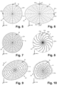
- FIGs 5, 6, 7, 8, 9 and 10 illustrate various processing lines s for cutting the lenticle 21 in the cornea 22 of an eye 2 by means of scanning lines f, which are superimposed on the respective processing lines s and (as in Figure 2a illustrated) have an orientation angle ⁇ ' to the machining line s.
- the processing lines s run transversely to the meridians m of the lenticle 21, i.e. the processing lines s do not run along the meridians m of the lenticle 21, but intersect at least one of the meridians m of the lenticle 21.
- the processing lines s according to Figures 5, 6, 9 and 10 each run in the x/y processing plane, although at different heights or depths in the z-direction, but a change in the z-direction during the scanning of a closed processing line s by the second scanner module 15 is not necessary.
- the processing lines s according to the Figures 7, 8 , 12 and 13 is an adjustment in the z-direction required during the scanning of a machining line s by the second scanner module 15.
- the z component of these height-varying processing lines s is adapted to the outer surface 21o, 21u by appropriate control of the second scanner module 15 or a separate focusing device by the circuit 10.
- one of the focusing optics is used for this purpose 16 upstream and the z-modulator 13, 13 'before or after adjustable optics provided (e.g. with displaceable lenses), which is set up to move the z-modulator 13, 13' tilted or curved scan line f vertically in the z-direction .
- adjustable optics cannot fulfill the task of the z modulator 13, 13' or divergence modulator 130, since on the one hand they are not synchronized with the scanner module 12 and on the other hand they cause a focus shift in the z Direction can also not perform fast enough to be able to be synchronized with the scanning movement or the corresponding scanning angle of the scanner module 12 (fast scan module).
- These adjustable optics also do not allow an adjustable tilting of the scan line f, as is achieved with the variant in which the z modulator tilts the focusing optics 16 about an axis of rotation,
- the figure 5 shows a sectional design with a plurality of circular machining lines arranged concentrically to the optical axis of the eye 2 s
- figure 6 shows a sectional design with several elliptical machining lines s, which are arranged concentrically to the optical axis of the eye 2.
- the figure 7 shows a cutting design with a spiral processing line s with a spiral center on the optical axis of the eye 2.
- the figure 8 shows a cut execution with several spiral-arm-shaped processing lines s, which proceed from the peripheral edge 21r of the lenticle 21 towards a center point on the optical axis of the eye 2 (or vice versa).
- the figure 9 shows a sectional version with several elliptical processing lines s, which are arranged concentrically to the optical axis of the eye 2, the longitudinal and transverse axes of the lenticule 21s being different from the lenticule 21 of FIG figure 6 is rotated about the optical axis of the eye 2 in the x/y processing plane, as indicated by the arrow 3 .
- the figure 10 shows a cutting design with several processing lines s, each of which is defined by a free-form closed curve.
- the cut according to the figure 7 has the advantage that, when cutting a (three-dimensional) lenticle 21, it allows a slow and continuous height adjustment of the processing line s and thus of the scanning line f running transversely thereto; that is, sudden and faster changes in the z-direction can be dispensed with.
- the alignment or the alignment angle ⁇ ′ of the scan line f to the processing line s is dynamically changed and adjusted by the rotator 14, controlled by the circuit 10, depending on the current position of the processing target point F on the processing line s during processing.
- the scan line f9, f10 each have an orientation angle ⁇ ′ of 90°, i.e. a normal orientation to the processing line s, which is achieved by the rotator 14 by continuously changing and adapting the rotation angle ⁇ to the processing line s.
- the scan line 11 is aligned to the processing line s with an orientation angle ⁇ '1 that is not rotated normal to the processing line s, so that, compared to a scan line f oriented normal to the processing line s, during processing in the narrower area of the elliptical lenticle 21, a narrowed processing path or cutting path is generated.
- the scanning line f12 is aligned normal to the processing line s with the orientation angle ⁇ ′2 in order to generate a wider processing path or cutting path in the longer area of the elliptical lenticle 21 .
- the scan line f13 is aligned normal to the processing line s with the alignment angle ⁇ '3, but compared to the scan lines f11 and f12 it has a shorter length t set by the scan length modulator 18 in order to have a to produce a narrowed machining path or cutting path.
- the scanning lines superimposed on the spiral or elliptical processing lines s are dynamically changed during processing with regard to their orientation angle ⁇ ' to the processing line s, their length t and/or their tilting angle ⁇ or their curvature depending on the current position of the processing target point F on the processing line s and adjusted to produce the lenticle 21 with spiral or elliptical machining paths or cutting paths, respectively.
- the scanning lines superimposed on the processing lines s are dynamically changed and adjusted during processing with regard to their alignment angle ⁇ ' to the processing line s, their length t and their tilting angle ⁇ or their curvature depending on the current position of the processing target point F on the processing line s in order to 21 with a predetermined free form to correct a higher-order aberration.
- the orientation angle ⁇ ' and the length of the scan line F12, F13, F14 are as in the example of FIG figure 8 depending on the current position of the processing target point F on the spiral arm s1, s2 is dynamically changed and adjusted during processing in order to produce the lenticle 21 with spiral arm-shaped processing paths or cutting paths, the width of which increases starting from the peripheral edge 21r of the lenticle 21 to the center point on the optical axis of the eye 2 is reduced, or increased again from the central point to the peripheral edge 21r.
- the spiral arm-shaped processing lines s1, s2 are not guided to the center point on the optical axis of the eye 2, but round one Forming free space M and maintaining a predetermined distance from the center point, it is guided around the center point, so that a spiral arm s1, starting from the peripheral edge 21r, is guided to the limit of the free space M and, starting from this, as a spiral arm s2, is guided back to the peripheral edge 21r of the lenticle 21 (or the other way around).
- the length of the scan lines superimposed on the spiral-shaped processing lines at the boundary of the free space M is set in such a way that the fewest possible overlaps are caused when the free space M is processed by the scan lines.
- the Figures 13 and 14 show a sectional design with a plurality of machining lines s, which run in planes running parallel to the optical axis of the eye 2 and each intersect a plurality of meridians m of the lenticle 21.
- the scanning lines f17, f18 superimposed on the processing lines s are each aligned with an orientation angle ⁇ ′ of 90°, ie normal to the processing line s in question.
- the scan lines f17, f18 are each tilted at a tilt angle ⁇ 17, ⁇ 18 from the x/y processing plane in order to adapt them to the course of the upper or lower outer surface 21o, 21u of the lenticle 21 to be cut.
- FIG. 12 shows a cross section of a lenticule 21 with upper and lower outer surfaces 21o, 21u and a peripheral edge 21r, which are cut into the eye tissue of the cornea 2 in the applanated state of the cornea to correct hyperopia.
- the upper and lower outer surface 21o, 21u of the lenticle 21 are cut with a design according to one of Figures 5, 6, 7, 8, 9, 10 , 12 or 14 cut.
- the peripheral edge 21r is cut with a scan line which is tilted by 90° from the x/y processing plane and which is superimposed on a processing line s surrounding the lenticle 21 to be cut in the peripheral edge 21r.
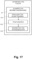
- the circuit 10 controls the scanner system 100 or its optical functional modules in order to direct the pulsed laser beam to processing target points F in the eye tissue 20 .
- the circuit 10 controls the scanner system 100 in step S1 such that the pulsed laser beam scans the eye tissue 20 in processing paths which run parallel to one another or which run next to one another and have a spiral, circular or elliptical shape.
- the second scanner module 15 of the scanner system 100 deflects the pulsed laser beam in the feed direction v to the processing target points F along a processing line s
- the first scanner module 12 of the scanner system 100 deflects the pulsed laser beam to the processing target points F along a scan line f that runs transversely to the processing line s, as shown in FIG the Figures 2a, 2b and 4-14 illustrated and described above with reference to these figures, so that in step S11 a cutting path defined by the machining path is generated.
- step S11 the switching circuit 10 controls the scanner system 100 or its optical functional modules in such a way that the cutting paths are generated in a plurality of processing paths, with the remaining tissue bridges between the cutting paths being left in each case.
- this is in figure 15 illustrated using the example of spiral machining lines or spiral machining paths defined thereby and the resulting cutting path 30 .
- the processing paths 3 running alongside one another can be seen.
- the processing paths 3 running next to one another are processed in step S11 in such a way that cutting paths 30 are produced in the processed processing paths, which are separated by tissue bridges 31 in intermediate, still unprocessed processing paths.
- the machining paths 3 or cutting paths 30 based thereon run parallel next to one another or run next to one another in a spiral, circular, elliptical manner or in freely closed curves.
- the circuit 10 controls the measuring system 17 in such a way that it detects the cutting paths 30 produced and determines the remaining tissue bridges 31 based on the cutting paths 30 produced. On the basis of the tissue bridges 31 determined, the circuit 10 determines the untreated processing paths that still need to be treated.
- reference numeral 32 refers to a recorded section of the generated cutting paths 30a, 30b for determining the intervening tissue bridge 310 and the corresponding processing path still to be processed.
- the generated cutting paths 30a, 30b are detected and the tissue bridge 310 in between is determined for positioning the processing path to be processed continuously during the Processing ("online"), so that the current processing target point F of the processing line s or the scan line f aligned transversely thereto follows (“upstream”) the recorded section 32 ("downstream”) of the generated cutting paths 30a, 30b in the processing direction v.
- the circuit 10 controls the scanner system 100 or its optical functional modules in such a way that the specific tissue bridges 31 or still untreated processing paths are processed.
- the scanner system 100 is controlled such that it directs the pulsed laser beam to processing target points F in the tissue bridges 31 remaining between the cutting paths 30 in order to complete the tissue cut.
- the tissue bridges are processed in processing paths 3, the width of which exceeds the width of the specific tissue bridges 31.
- the figure 18 illustrates a cutting method with which a lenticule 21 is cut in the eye tissue 20 in a sequence of cutting sequences.
- the circuit 10 controls the scanner system 100 or its optical functional modules in such a way that in step S2 the processing paths 30 are processed on the lower outer surface 21u of the lenticle 21 to be cut and in step S21 the cutting paths 30 with remaining tissue bridges 31 are produced, as referred to above to figure 17 was described in connection with steps S1 and S11.
- the lower outer surface 21u of the lenticle 21 is formed in steps S2, S21 initially cut incompletely with remaining tissue bridges 31 between the cutting paths 30.
- step S3 in contrast to cutting the cut surface according to the figure 17 started cutting the upper outer surface 21o of the lenticle 21 beforehand.
- the switching circuit 10 controls the scanner system 100 or its optical functional modules in such a way that in step S3 the processing paths 30 are processed on the upper outer surface 21o of the lenticle 21 to be cut.
- the circuit 10 controls the measuring system 17 in such a way that it detects the cutting paths 30 generated in step S2 or S21 on the lower outer surface 21u, and the processing paths 3 to be machined or the cutting paths 30 to be cut on the upper outer surface 21o determined based on the generated cutting paths 30 of the lower outer surface 21u.
- the circuit 10 also controls the measuring system 17 in such a way that the measuring system 17 detects deformations in the eye tissue caused by gas bubbles generated when cutting the cutting paths 30 on the lower outer surface 21u, and the upper outer surface 21o, or those to be processed Machining paths 3 and cutting paths 30 to be cut thereby on the upper outer surface 21o are positioned with respect to the detected lower outer surface 21u, taking into account the detected deformations.
- the switching circuit 10 then controls the scanner system 100 or its optical functional modules in such a way that in step S32 the incision paths 30 are produced with the remaining tissue bridges 31 on the upper outer surface 21o, as described above with reference to FIG figure 17 was described in connection with steps S1 and S11.
- the circuit 10 determines the machining paths 3 for the production of the cutting paths 30 on the upper outer surface 21o with a smaller path width in relation to the detected cutting paths 30 on the lower outer surface 21u.
- the upper outer surface 21o of the lenticle 21 is also incompletely cut with tissue bridges 31 remaining between the cutting tracks 30.
- the switching circuit 10 controls the scanner system 100 or its optical functional modules in such a way that in step S4 the processing paths 30 with the remaining tissue bridges 31 on the lower outer surface 21u of the lenticle 21 to be cut are processed.
- the circuit 10 controls the measuring system 17 in such a way that it detects the cutting paths 30 already produced on the lower outer surface 21u and determines the remaining tissue bridges 31 based on the cutting paths 30 detected. On the basis of the tissue bridges 31 determined, the circuit 10 determines the untreated machining paths yet to be treated on the lower outer surface 21u.
- step S42 the switching circuit 10 controls the scanner system 100 or its optical functional modules in such a way that the remaining tissue bridges 31 or still untreated processing paths are processed and thereby cut, as described above with reference to FIG figure 17 as described in connection with step S13, thereby completing the tissue cut on the lower outer surface 21u of the lenticle 21.
- the switching circuit 10 controls the scanner system 100 or its optical functional modules in such a way that in step S5 the processing paths 30 with the remaining tissue bridges 31 be processed on the upper outer surface 21o of the lenticle 21 to be cut.
- the circuit 10 controls the measuring system 17 in such a way that it detects the cutting paths 30 already produced on the upper outer surface 21o and determines the remaining tissue bridges 31 based on the cutting paths 30 detected. On the basis of the tissue bridges 31 determined, the circuit 10 determines the untreated machining paths that are still to be treated on the upper outer surface 21o.
- step S52 the switching circuit 10 controls the scanner system 100 or its optical functional modules in such a way that the remaining tissue bridges 31 or still untreated processing paths are processed, as described above with reference to FIG figure 17 as described in connection with step S13, and thereby completes the tissue cut on the upper outer surface 21o of the lenticle 21, whereby the lenticle 21 is completely cut.
Abstract
Zum Bearbeiten von Augengewebe (20) umfasst eine ophthalmologische Vorrichtung (1) eine Laserquelle (11), die eingerichtet ist, einen gepulsten Laserstrahl (L) zu erzeugen, eine Fokussieroptik (16), die eigerichtet ist, den gepulsten Laserstrahl ins Augengewebe (20) zu fokussieren, und ein Scannersystem (100) zum Ablenken des gepulsten Laserstrahls mit sich überlappenden Laserpulsspots (P) auf aufeinanderfolgende Bearbeitungszielpunkte (F) im Augengewebe (20). Ein Schaltkreis (10) steuert das Scannersystem (100) derart, dass das Scannersystem (100) den gepulsten Laserstrahl in nebeneinander verlaufende Bearbeitungsbahnen lenkt, um zunächst durch verbleibende Gewebebrücken getrennte Schnittbahnen eines auf einer Fläche vorzunehmenden Gewebeschnitts zu erzeugen, und danach den gepulsten Laserstrahl in die verbleibenden Gewebebrücken zwischen den Schnittbahnen lenkt, um den Gewebeschnitt zu vervollständigen.For processing eye tissue (20), an ophthalmological device (1) comprises a laser source (11) that is set up to generate a pulsed laser beam (L), focusing optics (16) that are set up to direct the pulsed laser beam into the eye tissue (20 ) to focus, and a scanner system (100) for deflecting the pulsed laser beam with overlapping laser pulse spots (P) to successive processing target points (F) in the eye tissue (20). A switching circuit (10) controls the scanner system (100) in such a way that the scanner system (100) directs the pulsed laser beam into processing paths running next to one another in order to first generate cutting paths, separated by remaining tissue bridges, of a tissue cut to be made on a surface, and then the pulsed laser beam into guides the remaining bridges of tissue between the cutting lanes to complete the tissue cut.
Description
Die vorliegende Erfindung betrifft eine ophthalmologische Vorrichtung zum Bearbeiten von Augengewebe mittels eines gepulsten Laserstrahls. Die vorliegende Erfindung betrifft insbesondere eine ophthalmologische Vorrichtung mit einer Laserquelle zur Erzeugung eines gepulsten Laserstrahls, einer Fokussieroptik zur Fokussierung des gepulsten Laserstrahls ins Augengewebe und ein Scannersystem, um den gepulsten Laserstrahl auf einen Bearbeitungszielpunkt im Augengewebe zu lenken.The present invention relates to an ophthalmological device for processing eye tissue using a pulsed laser beam. The present invention relates in particular to an ophthalmological device with a laser source for generating a pulsed laser beam, focusing optics for focusing the pulsed laser beam into the ocular tissue, and a scanner system for directing the pulsed laser beam to a processing target point in the ocular tissue.
Zum Bearbeiten von Augengewebe mittels eines Laserstrahls wird ein Bearbeitungsbereich mit Laserpulsen gescannt (abgetastet), indem der gepulste Laserstrahl mittels geeigneter Scannersysteme (Ablenkvorrichtungen) in ein oder zwei Scannrichtungen (Abtastrichtungen) abgelenkt wird. Die Ablenkung der Lichtstrahlen respektive der Laserpulse, beispielsweise Femtosekundenlaserpulse, wird im Allgemeinen mit beweglichen Spiegeln vorgenommen, die um eine oder zwei Scannachsen schwenkbar sind, beispielsweise mit Galvanoscannern, Piezoscannern, Polygonscannern oder Resonanzscannern.To process eye tissue using a laser beam, a processing area is scanned (scanned) with laser pulses by deflecting the pulsed laser beam in one or two scanning directions (scanning directions) using suitable scanner systems (deflection devices). The light beams or the laser pulses, for example femtosecond laser pulses, are generally deflected using movable mirrors which can be pivoted about one or two scanning axes, for example using galvano scanners, piezo scanners, polygon scanners or resonance scanners.
In
Derartige bekannte Systeme ermöglichen zwar die Bearbeitung von einfachen Scannmustern, beispielsweise das Schneiden eines Gewebelappens (Flap), das in der Regel als grosses Flächenstück mit einfacher Randgeometrie ausgeführt wird. Bei Anwendungen, in denen nicht nur Gewebeschnitte in einer im Wesentlichen horizontal ausgerichteten Bearbeitungsfläche auf einer gemeinsamen Fokalfläche ausgeführt werden, sondern in denen auch Schnitte mit einer vertikalen Schnittkomponente über unterschiedliche Fokushöhen ausgeführt werden sollen, z.B. schräg zur Horizontalen verlaufende oder vertikale Schnitte, erweist sich das vertikale Verfahren der Projektionsoptik oder eines Zoom-Systems für eine vertikale Veränderung des Fokus und damit der Schnitthöhe als zu langsam um Schnitte mit einer vertikalen Komponente, also mit veränderlicher Fokustiefe während des Schneidens, mit einer Geschwindigkeit auszuführen, die vergleichbar ist mit Schnittgeschwindigkeiten in der horizontalen Bearbeitungsfläche.Known systems of this type allow the processing of simple scan patterns, for example the cutting of a flap of tissue (flap), which is generally designed as a large area piece with a simple edge geometry. This proves to be the case in applications in which tissue cuts are not only made in a substantially horizontally aligned processing area on a common focal surface, but in which cuts with a vertical cut component are also to be made over different focal heights, e.g. diagonal to the horizontal or vertical cuts vertical processes of the projection optics or a zoom system for a vertical change in the focus and thus the cutting height as too slow to perform cuts with a vertical component, i.e. with a variable focus depth during cutting, at a speed that is comparable to cutting speeds in the horizontal processing area.
Es ist eine Aufgabe der vorliegenden Erfindung eine Vorrichtung zum Bearbeiten von Augengewebe mittels eines gepulsten Laserstrahls vorzuschlagen, welche zumindest einige Nachteile des Stands der Technik nicht aufweist.It is an object of the present invention to propose a device for processing eye tissue using a pulsed laser beam, which does not have at least some of the disadvantages of the prior art.
Gemäss der vorliegenden Erfindung werden diese Ziele durch die Merkmale der unabhängigen Ansprüche erreicht. Weitere vorteilhafte Ausführungsformen gehen ausserdem aus den abhängigen Ansprüchen und der Beschreibung hervor.According to the present invention, these objects are achieved by the features of the independent claims. Further advantageous embodiments also emerge from the dependent claims and the description.
In einem ersten Aspekt der vorliegenden Erfindung umfasst eine ophthalmologische Vorrichtung zum Bearbeiten von Augengewebe eine Laserquelle, die eingerichtet ist, einen gepulsten Laserstrahl zu erzeugen; eine Fokussieroptik, die eigerichtet ist, den gepulsten Laserstrahl ins Augengewebe zu fokussieren; und ein Scannersystem, das eingerichtet ist, den gepulsten Laserstrahl auf Bearbeitungszielpunkte im Augengewebe zu lenken; und die oben genannten Ziele werden wenigstens teilweise dadurch erreicht, dass der Schaltkreis eingerichtet, das Scannersystem derart zu steuern, dass das Scannersystem den gepulsten Laserstrahl auf Bearbeitungszielpunkte lenkt auf eine in einer Hornhaut zu schneidende Fläche, in nebeneinander verlaufenden Bearbeitungsbahnen, um zunächst durch verbleibende Gewebebrücken getrennte Schnittbahnen eines auf der Fläche vorzunehmenden Gewebeschnitts zu erzeugen, und danach den gepulsten Laserstrahl auf Bearbeitungszielpunkte in die verbleibenden Gewebebrücken zwischen den Schnittbahnen auf der Fläche lenkt, um den Gewebeschnitt zu vervollständigen. Das Schneiden von durch Gewebebrücken getrennten Schnittbahnen ermöglicht jeweils eine neue Schnittbahn zu schneiden, ohne dass diese durch Verformungen beeinträchtigt wird, die durch Gasbildung in einer bereits geschnittenen direkt benachbarten Schnittbahn verursacht werden.In a first aspect of the present invention, an ophthalmological device for processing eye tissue comprises a laser source which is set up to generate a pulsed laser beam; focusing optics configured to focus the pulsed laser beam into the ocular tissue; and a scanner system configured to direct the pulsed laser beam to processing target points in the eye tissue; and the above objects are achieved at least in part by the circuitry being arranged to control the scanner system such that the scanner system directs the pulsed laser beam to machining target points on an in a surface to be cut on a cornea, in processing paths running next to one another, in order to first produce cutting paths, separated by remaining tissue bridges, of a tissue section to be made on the surface, and then to direct the pulsed laser beam to processing target points in the remaining tissue bridges between the cutting paths on the surface, in order to close the tissue section to complete. The cutting of cutting paths separated by tissue bridges enables a new cutting path to be cut at a time without being affected by deformations caused by gas formation in an already cut immediately adjacent cutting path.
In einer Ausführungsvariante umfasst die ophthalmologische Vorrichtung ein Messsystem, das eingerichtet ist, Strukturen im Augengewebe optisch zu erfassen. Der Schaltkreis ist eingerichtet, das Messsystem derart zu steuern, dass das Messsystem die erzeugten Schnittbahnen erfasst, und die Bearbeitungszielpunkte in den verbleibenden Gewebebrücken basierend auf den erfassten Schnittbahnen positioniert. In einer Ausführungsvariante ist das Messsystem als interferometrisches Messsystem ausgeführt. Die Erfassung bereits geschnittener Schnittbahnen und die Bearbeitung von verbliebenen Gewebebrücken unter Berücksichtigung der bereits geschnittenen Schnittbahnen ermöglicht eine flexible Anpassung an die tatsächliche Form durchgeführter Schnittbahnen und dadurch eine Vermeidung oder zumindest Reduktion von überlappenden Schnittbahnen über ausgedehnte Gebiete.In one embodiment variant, the ophthalmological device includes a measuring system that is set up to optically detect structures in the eye tissue. The circuit is set up to control the measurement system in such a way that the measurement system detects the generated cutting paths and positions the processing target points in the remaining tissue bridges based on the detected cutting paths. In one embodiment variant, the measuring system is designed as an interferometric measuring system. The detection of incision paths that have already been cut and the processing of remaining tissue bridges, taking into account the incision paths that have already been cut, enables flexible adaptation to the actual shape of incision paths that have been carried out and thus avoids or at least reduces overlapping incision paths over extensive areas.
In einer weiteren Ausführungsvariante ist der Schaltkreis eingerichtet, das Scannersystem derart zu steuern, dass das Scannersystem den gepulsten Laserstrahl mit sich überlappenden Laserpulsspots auf aufeinanderfolgende Bearbeitungszielpunkte lenkt.In a further embodiment variant, the circuit is set up to control the scanner system in such a way that the scanner system directs the pulsed laser beam with overlapping laser pulse spots onto successive processing target points.
In einer Ausführungsvariante ist der Schaltkreis eingerichtet, das Scannersystem derart zu steuern, dass das Scannersystem den gepulsten Laserstrahl auf Bearbeitungszielpunkte in den nebeneinander verlaufenden Bearbeitungsbahnen in die verbleibenden Gewebebrücken lenkt.In one embodiment variant, the circuit is set up to control the scanner system in such a way that the scanner system directs the pulsed laser beam to processing target points in the processing paths running next to one another in the remaining tissue bridges.
In einer weiteren Ausführungsvariante ist der Schaltkreis eingerichtet, das Scannersystem derart zu steuern, dass das Scannersystem den gepulsten Laserstrahl in den verbleibenden Gewebebrücken auf Bearbeitungszielpunkte in Bearbeitungsbahnen lenkt, welche eine über die Gewebebrücken hinausgehende Breite aufweisen.In a further embodiment variant, the circuit is set up to control the scanner system in such a way that the scanner system directs the pulsed laser beam in the remaining tissue bridges to processing target points in processing paths which have a width exceeding the tissue bridges.
In einer Ausführungsvariante ist der Schaltkreis eingerichtet, das Scannersystem derart zu steuern, dass das Scannersystem den gepulsten Laserstrahl auf Bearbeitungszielpunkte in parallel nebeneinander verlaufenden Bearbeitungsbahnen lenkt.In one embodiment variant, the circuit is set up to control the scanner system in such a way that the scanner system directs the pulsed laser beam to processing target points in processing paths running parallel next to one another.
In einer weiteren Ausführungsvariante ist der Schaltkreis eingerichtet, das Scannersystem derart zu steuern, dass das Scannersystem den gepulsten Laserstrahl auf Bearbeitungszielpunkte in nebeneinander verlaufenden Bearbeitungsbahnen lenkt, die eine spiralförmige, kreisförmige oder elliptische Form aufweisen.In a further embodiment variant, the circuit is set up to control the scanner system in such a way that the scanner system directs the pulsed laser beam to processing target points in processing paths running next to one another, which have a spiral, circular or elliptical shape.
In einer Ausführungsvariante ist der Schaltkreis eingerichtet, das Scannersystem derart zu steuern, dass das Scannersystem den gepulsten Laserstrahl in einer Vorschubrichtung auf Bearbeitungszielpunkte entlang einer in den Bearbeitungsbahnen verlaufenden Bearbeitungslinie lenkt. Das Scannersystem ist eingerichtet, den gepulsten Laserstrahl entlang einer quer zur Bearbeitungslinie verlaufenden Scannlinie innerhalb der Bearbeitungsbahnen zu lenken, mit einer wesentlich höheren Scanngeschwindigkeit im Vergleich zur Scanngeschwindigkeit in Vorschubrichtung.In one embodiment variant, the circuit is set up to control the scanner system in such a way that the scanner system directs the pulsed laser beam in a feed direction to processing target points along a processing line running in the processing paths. The scanner system is set up, the pulsed laser beam along a scan line running transversely to the processing line within the To steer machining paths, with a significantly higher scanning speed compared to the scanning speed in the feed direction.
In einer weiteren Ausführungsvariante ist der Schaltkreis eingerichtet, das Scannersystem derart zu steuern, dass das Scannersystem den gepulsten Laserstrahl auf Bearbeitungszielpunkte auf einer Aussenfläche eines in einer Hornhaut zu schneidenden Lentikels lenkt, in den nebeneinander verlaufenden Bearbeitungsbahnen, um die durch verbleibende Gewebebrücken getrennten Schnittbahnen des vorzunehmenden Gewebeschnitts an der Aussenfläche des Lentikels zu erzeugen, und danach den gepulsten Laserstrahl auf Bearbeitungszielpunkte in die verbleibenden Gewebebrücken zwischen den Schnittbahnen auf der Aussenfläche des Lentikels lenkt, um den Gewebeschnitt zu vervollständigen.In a further embodiment variant, the circuit is set up to control the scanner system in such a way that the scanner system directs the pulsed laser beam to processing target points on an outer surface of a lenticule to be cut in a cornea, in the processing paths running next to each other, in order to cut paths of the to be made, which are separated by remaining tissue bridges tissue section on the outer surface of the lenticle, and thereafter directs the pulsed laser beam to processing target points in the remaining bridges of tissue between the cutting paths on the outer surface of the lenticle to complete the tissue section.
In einer Ausführungsvariante ist der Schaltkreis eingerichtet, das Scannersystem derart zu steuern, dass das Scannersystem den gepulsten Laserstrahl auf Bearbeitungszielpunkte auf die von einer äusseren Hornhautoberfläche abgewandte untere Aussenfläche des zu schneidenden Lentikels lenkt, um die durch verbleibende Gewebebrücken getrennten Schnittbahnen auf der unteren Aussenfläche des zu schneidenden Lentikels zu erzeugen, und dass das Scannersystem den gepulsten Laserstrahl danach auf Bearbeitungszielpunkte lenkt auf einer von der äusseren Hornhautoberfläche zugewandten oberen Aussenfläche des zu schneidenden Lentikels, in nebeneinander verlaufenden Bearbeitungsbahnen, um durch verbleibende Gewebebrücken getrennte Schnittbahnen eines an der oberen Aussenfläche des Lentikels vorzunehmenden oberen Gewebeschnitts zu erzeugen, bevor das Scannersystem den gepulsten Laserstrahl auf die Bearbeitungszielpunkte in die verbleibenden Gewebebrücken auf der unteren Aussenfläche des Lentikels lenkt, um den unteren Gewebeschnitt zu vervollständigen; und dass das Scannersystem danach den gepulsten Laserstrahl auf Bearbeitungszielpunkte in die verbleibenden Gewebebrücken auf der oberen Aussenfläche des Lentikels lenkt, um den oberen Gewebeschnitts zu vervollständigen.In one embodiment variant, the circuit is set up to control the scanner system in such a way that the scanner system directs the pulsed laser beam to processing target points on the lower outer surface of the lenticule to be cut, which is remote from an outer corneal surface, in order to cut the cutting paths, separated by remaining tissue bridges, on the lower outer surface of the cutting lenticule, and that the scanner system then directs the pulsed laser beam to processing target points on an upper outer surface of the lenticle to be cut, facing the outer corneal surface, in processing paths running next to one another, in order to cut paths, separated by remaining tissue bridges, of an upper one to be carried out on the upper outer surface of the lenticle tissue section before the scanner system applies the pulsed laser beam to the processing target points in the remaining tissue bridges on the lower outer surface of the lenticle to complete the lower tissue section; and the scanner system thereafter directing the pulsed laser beam to machining target points in the remaining bridges of tissue on the upper surface of the lenticle to complete the upper tissue section.
In einer weiteren Ausführungsvariante umfasst die ophthalmologische Vorrichtung ein Messsystem, das eingerichtet ist, Strukturen im Augengewebe optisch zu erfassen. Der Schaltkreis ist eingerichtet, das Messsystem derart zu steuern, dass das Messsystem die erzeugten Schnittbahnen des vorzunehmenden unteren Gewebeschnitts erfasst, und die Bearbeitungsbahnen des vorzunehmenden oberen Gewebeschnitts bezüglich der erfassten Schnittbahnen des unteren Gewebeschnitts positioniert. In einer Ausführungsvariante ist das Messsystem als interferometrisches Messsystem ausgeführt.In a further embodiment variant, the ophthalmological device comprises a measuring system that is set up to optically detect structures in the eye tissue. The circuit is set up to control the measurement system in such a way that the measurement system detects the generated cutting paths of the lower tissue incision to be made and positions the processing paths of the upper tissue incision to be made with respect to the recorded cutting paths of the lower tissue incision. In one embodiment variant, the measuring system is designed as an interferometric measuring system.
In einer weiteren Ausführungsvariante ist der Schaltkreis eingerichtet, die Bearbeitungsbahnen des vorzunehmenden oberen Gewebeschnitts bezüglich der erfassten Schnittbahnen des unteren Gewebeschnitts mit kleinerer Bahnbreite zu bestimmen.In a further embodiment variant, the circuit is set up to determine the processing paths of the upper tissue incision to be made with reference to the detected incision paths of the lower tissue incision with a smaller path width.
In einer Ausführungsvariante ist der Schaltkreis eingerichtet, die Bearbeitungsbahnen zur Vervollständigung des unteren Gewebeschnitts bezüglich der erfassten Schnittbahnen des unteren Gewebeschnitts zu positionieren.In one embodiment variant, the circuit is set up to position the processing paths for completing the lower tissue incision with respect to the detected incision paths of the lower tissue incision.
In einem zweiten Aspekt der vorliegenden Erfindung umfasst die ophthalmologische Vorrichtung zum Bearbeiten von Augengewebe, insbesondere zum Schneiden eines Lentikels im Augengewebe, eine Laserquelle, die eingerichtet ist, einen gepulsten Laserstrahl zu erzeugen; eine Fokussieroptik, die eigerichtet ist, den gepulsten Laserstrahl ins Augengewebe zu fokussieren; ein Scannersystem, umfassend ein erstes Scannermodul und ein zweites Scannermodul, zum Ablenken des gepulsten Laserstrahls auf Bearbeitungszielpunkte im Augengewebe; und einen Schaltkreis zur Steuerung der ophthalmologischen Vorrichtung; und die oben genannten Ziele werden wenigstens teilweise dadurch erreicht, dass der Schaltkreis eingerichtet ist, das zweite Scannermodul derart zu steuern, dass das zweite Scannermodul den gepulsten Laserstrahl in einer Vorschubrichtung auf Bearbeitungszielpunkte entlang einer Bearbeitungslinie lenkt, die auf einer Aussenfläche eines im Augengewebe zu schneidenden Lentikels quer zu Meridianen des Lentikels verläuft. Das erste Scannermodul ist eingerichtet, den gepulsten Laserstrahl auf Bearbeitungszielpunkte entlang einer um einen Ausrichtungswinkel quer zur Bearbeitungslinie in einer horizontalen Bearbeitungsebene verlaufenden Scannlinie zu lenken, mit einer wesentlich höheren Scanngeschwindigkeit im Vergleich zur Scanngeschwindigkeit des zweiten Scannermoduls in Vorschubrichtung. Die ophthalmologische Vorrichtung umfasst einen z-Modulator, der eingerichtet ist, die Scannlinie abhängig von einem bestimmten Bearbeitungszielpunkt des zweiten Scannermoduls auf der Bearbeitungslinie derart aus der Bearbeitungsebene zu verkippen, dass die Scannlinie im Wesentlichen entlang der Aussenfläche des Lentikels verläuft. Durch diese vom aktuellen Bearbeitungszielpunkt der (vergleichsweise langsamer gescannten) Bearbeitungslinie abhängige Verkippung der (vergleichsweise schneller gescannten) Sannlinie können im Augengewebe Lentikel mit mehreren nebeneinanderliegenden aus der horizontalen Bearbeitungsebene verkippten Schnittbahnen geschnitten werden, ohne dass dabei wesentliche Abweichungen zur Oberflächenkrümmung des zu schneidenden Lentikels erzeugt werden. Insbesondere im Vergleich zu Lösungen mit fest horizontal ausgerichteten Scannlinien, die keine optimale Schnittanpassung an Oberflächenkrümmungen von Lentikeln erlauben, ermöglicht die dynamische Änderung der Scannlinienverkippung eine flexiblere und präzisere Schnittanpassung an Lentikeloberflächen mit örtlich variierender Oberflächenkrümmung. Abhängig von der gewählten Form der Bearbeitungslinie, können die Lentikel im Augengewebe überdies geschnitten werden, ohne dass dazu vertikale Fokusverschiebungen in der Grössenordnung und im Ausmass der gesamten Tiefe der durchzuführenden vertikalen Schnittkomponente, also der Dicke des zu schneidenden Lentikels, durch Verschiebungen der Projektionsoptik oder Bewegungen von Linsen eines Zoomsystems mit einer Geschwindigkeit vorgenommen werden müssen, mit der das zweite Scannermodul eine der lateralen Ausdehnung des zu schneidenden Lentikels entsprechende Distanz der Bearbeitungslinie abfährt.In a second aspect of the present invention, the ophthalmological device for processing ocular tissue, in particular for cutting a lenticule in the ocular tissue, comprises a laser source which is set up to produce a pulsed to generate laser beam; focusing optics configured to focus the pulsed laser beam into the ocular tissue; a scanner system, comprising a first scanner module and a second scanner module, for deflecting the pulsed laser beam onto processing target points in the eye tissue; and a circuit for controlling the ophthalmic device; and the above objects are achieved at least in part by the circuit being configured to control the second scanner module such that the second scanner module directs the pulsed laser beam in a feed direction to processing target points along a processing line defined on an outer surface of an eye tissue to be cut Lenticle runs transversely to meridians of the lenticle. The first scanner module is set up to direct the pulsed laser beam to processing target points along a scan line running at an orientation angle transverse to the processing line in a horizontal processing plane, with a significantly higher scanning speed compared to the scanning speed of the second scanner module in the feed direction. The ophthalmological device includes a z-modulator that is set up to tilt the scan line from the processing plane depending on a specific processing target point of the second scanner module on the processing line such that the scan line essentially runs along the outer surface of the lenticle. This tilting of the (comparatively faster scanned) scanning line, which is dependent on the current processing target point of the (comparatively more slowly scanned) processing line, lenticules can be cut in the eye tissue with several adjacent cutting paths tilted from the horizontal processing plane, without producing significant deviations from the surface curvature of the lenticule to be cut . In particular in Compared to solutions with fixed, horizontally aligned scan lines, which do not allow optimal cut adaptation to lenticule surface curvatures, the dynamic change in scan line tilt enables more flexible and precise cut adaptation to lenticule surfaces with locally varying surface curvatures. Depending on the selected shape of the processing line, the lenticules in the eye tissue can also be cut without vertical focus shifts in the order of magnitude and extent of the total depth of the vertical cutting component to be carried out, i.e. the thickness of the lenticule to be cut, due to shifts in the projection optics or movements of lenses of a zoom system must be carried out at a speed with which the second scanner module covers a distance of the processing line corresponding to the lateral extent of the lenticle to be cut.
In einer Ausführungsvariante umfasst die ophthalmologische Vorrichtung einen Rotator, der eingerichtet ist, eine durch die Scannlinie und den gepulsten Laserstrahl definierte Fastscannebene derart um eine optische Übertragungsachse zu drehen, dass der Ausrichtungswinkel der Scannlinie zur Bearbeitungslinie verändert wird.In one embodiment variant, the ophthalmological device includes a rotator that is set up to rotate a fast scan plane defined by the scan line and the pulsed laser beam about an optical transmission axis in such a way that the alignment angle of the scan line to the processing line is changed.
In einer weiteren Ausführungsvariante ist der Schaltkreis eingerichtet, den Rotator abhängig vom bestimmten Bearbeitungszielpunkt des zweiten Scannermoduls auf der Bearbeitungslinie zu steuern, so dass der Ausrichtungswinkel der Scannlinie zur Bearbeitungslinie abhängig vom bestimmten Bearbeitungszielpunkt des zweiten Scannermoduls auf der Bearbeitungslinie eingestellt wird.In a further embodiment variant, the circuit is set up to control the rotator depending on the specific processing target point of the second scanner module on the processing line, so that the alignment angle of the scan line to the processing line is set depending on the specific processing target point of the second scanner module on the processing line.
In einer Ausführungsvariante umfasst die ophthalmologische Vorrichtung einen Scannlängenmodulator, der eingerichtet ist, eine Länge der Scannlinie zu verändern. Der Schaltkreis ist eingerichtet, den Scannlängenmodulator abhängig vom bestimmten Bearbeitungszielpunkt des zweiten Scannermoduls auf der Bearbeitungslinie derart zu steuern, dass die Länge der Scannlinie abhängig vom bestimmten Bearbeitungszielpunkt des zweiten Scannermoduls auf der Bearbeitungslinie eingestellt wird.In one embodiment variant, the ophthalmological device includes a scan length modulator that is set up to change a length of the scan line. The circuit is set up to control the scan length modulator depending on the specific processing target point of the second scanner module on the processing line such that the length of the scan line is adjusted depending on the specific processing target point of the second scanner module on the processing line.
In einer weiteren Ausführungsvariante ist der Schaltkreis eingerichtet, das zweite Scannermodul derart zu steuern, dass das zweite Scannermodul den gepulsten Laserstrahl auf Bearbeitungszielpunkte in der Bearbeitungsebene entlang einer kreisförmigen oder elliptischen Bearbeitungslinie lenkt, die auf der Aussenfläche des Lentikels verläuft.In a further embodiment variant, the circuit is set up to control the second scanner module in such a way that the second scanner module directs the pulsed laser beam to processing target points in the processing plane along a circular or elliptical processing line that runs on the outer surface of the lenticle.
In einer Ausführungsvariante ist der Schaltkreis eingerichtet, das zweite Scannermodul derart zu steuern, dass das zweite Scannermodul den gepulsten Laserstrahl nacheinander entlang mehrerer in übereinanderliegenden Bearbeitungsebenen angeordneten kreisförmigen oder elliptischen Bearbeitungslinien lenkt, die auf der Aussenfläche des Lentikels verlaufen.In one embodiment, the circuit is set up to control the second scanner module in such a way that the second scanner module directs the pulsed laser beam in succession along a plurality of circular or elliptical processing lines arranged in superimposed processing planes and running on the outer surface of the lenticle.
In einer weiteren Ausführungsvariante ist der Schaltkreis eingerichtet, das zweite Scannermodul derart zu steuern, dass das zweite Scannermodul den gepulsten Laserstrahl auf Bearbeitungszielpunkte entlang einer spiralförmigen Bearbeitungslinie lenkt, die auf der Aussenfläche des Lentikels verläuft.In a further embodiment variant, the circuit is set up to control the second scanner module in such a way that the second scanner module directs the pulsed laser beam to processing target points along a spiral processing line that runs on the outer surface of the lenticle.
In einer Ausführungsvariante ist der Schaltkreis eingerichtet, das zweite Scannermodul derart zu steuern, dass das zweite Scannermodul den gepulsten Laserstrahl auf Bearbeitungszielpunkte entlang einer Bearbeitungslinie lenkt, die in der der Form eines Kreisbogensegments, eines Spiralbogensegments oder eines gekrümmten Liniensegments auf der Aussenfläche des Lentikels verläuft.In one embodiment variant, the circuit is set up to control the second scanner module in such a way that the second scanner module directs the pulsed laser beam to processing target points along a processing line that runs in the form of a circular arc segment, a spiral arc segment or a curved line segment on the outer surface of the lenticle.
In einer weiteren Ausführungsvariante ist der Schaltkreis eingerichtet, das zweite Scannermodul derart zu steuern, dass das zweite Scannermodul den gepulsten Laserstrahl auf Bearbeitungszielpunkte entlang mehrerer spiralförmiger Bearbeitungslinien lenkt, die in einem ersten Schritt ausgehend von einer Peripherie der Aussenfläche des Lentikels spiralarmförmig in Richtung eines Zentrums der Aussenfläche verlaufen, und in einem zweiten Schritt ausgehend vom Zentrum spiralarmförmig zur Peripherie der Aussenfläche des Lentikels verlaufen.In a further embodiment variant, the circuit is set up to control the second scanner module in such a way that the second scanner module directs the pulsed laser beam to processing target points along a plurality of spiral processing lines which, in a first step, proceed from a periphery of the outer surface of the lenticule in the shape of a spiral arm in the direction of a center of the Run outer surface, and run in a second step starting from the center in a spiral arm shape to the periphery of the outer surface of the lenticle.
In einer Ausführungsvariante ist der Schaltkreis eingerichtet, das zweite Scannermodul derart zu steuern, dass das zweite Scannermodul den gepulsten Laserstrahl auf Bearbeitungszielpunkte entlang mehrerer spiralförmiger Bearbeitungslinien lenkt, die in einem ersten Schritt ausgehend von einer Peripherie der Aussenfläche des Lentikels spiralarmförmig in Richtung eines Zentrums der Aussenfläche verlaufen und mit einem bestimmten Abstand zum Zentrum enden, und in einem zweiten Schritt ausgehend vom bestimmten Abstand zum Zentrum spiralarmförmig zur Peripherie der Aussenfläche des Lentikels verlaufen, oder umgekehrt im ersten Schritt ausgehend vom bestimmten Abstand zum Zentrum spiralarmförmig zur Peripherie der Aussenfläche des Lentikels verlaufen und von der Peripherie der Aussenfläche des Lentikels spiralarmförmig in Richtung des Zentrums der Aussenfläche verlaufen.In one embodiment variant, the circuit is set up to control the second scanner module in such a way that the second scanner module directs the pulsed laser beam to processing target points along a plurality of spiral-shaped processing lines which, in a first step, proceed from a periphery of the outer surface of the lenticule in the shape of a spiral arm in the direction of a center of the outer surface run and end at a certain distance from the center, and in a second step, starting from a certain distance from the center, run in a spiral arm to the periphery of the outer surface of the lenticle, or conversely, in the first step, starting from a certain distance from the center, run in a spiral arm to the periphery of the outer surface of the lenticle and extend from the periphery of the outer surface of the lenticule in the shape of a spiral arm towards the center of the outer surface.
In einer weiteren Ausführungsvariante ist der z-Modulator eingerichtet, die Scannlinie bezüglich der Bearbeitungsebene zu krümmen. Der Schaltkreis ist eingerichtet, den z-Modulator abhängig vom bestimmten Bearbeitungszielpunkt des zweiten Scannermoduls auf der Bearbeitungslinie derart zu steuern, dass der z-Modulator die Scannlinie abhängig vom bestimmten Bearbeitungszielpunkt des zweiten Scannermoduls auf der Bearbeitungslinie zur Anpassung an die Aussenfläche des Lentikels krümmt.In a further embodiment variant, the z modulator is set up to curve the scan line with respect to the processing plane. The circuit is set up to control the z-modulator depending on the specific processing target point of the second scanner module on the processing line in such a way that the z-modulator curves the scan line depending on the specific processing target point of the second scanner module on the processing line for adaptation to the outer surface of the lenticle.
In einer Ausführungsvariante umfasst die ophthalmologische Vorrichtung einen Rotator, der eingerichtet ist, eine durch die Scannlinie und den gepulsten Laserstrahl definierte Fastscannebene um eine optische Übertragungsachse zu drehen, um den Ausrichtungswinkel der Scannlinie zur Bearbeitungslinie zu verändern. Der z-Modulator ist eingerichtet, die Scannlinie bezüglich der Bearbeitungsebene zu krümmen. Die ophthalmologische Vorrichtung umfasst einen Scannlängenmodulator, der eingerichtet ist, eine Länge der Scannlinie zu verändern. Der Schaltkreis ist eingerichtet, abhängig vom bestimmten Bearbeitungszielpunkt des zweiten Scannermoduls auf der Bearbeitungslinie den Rotator zum Einstellen des Ausrichtungswinkels der Scannlinie zur Bearbeitungslinie, den z-Modulator zur Krümmung der Scannlinie bezüglich der Bearbeitungsebene, und den Scannlängenmodulator zum Einstellen der Länge der Scannlinie derart zu steuern, dass die Aussenfläche des Lentikels in vorgegebener Freiform zur Korrektur einer Aberration höherer Ordnung geschnitten wird.In one embodiment variant, the ophthalmological device includes a rotator that is set up to rotate a fast scan plane defined by the scan line and the pulsed laser beam about an optical transmission axis in order to change the alignment angle of the scan line to the processing line. The z modulator is set up to curve the scan line with respect to the processing plane. The ophthalmological device includes a scan length modulator configured to change a length of the scan line. The circuit is set up, depending on the specific processing target point of the second scanner module on the processing line, to control the rotator for adjusting the orientation angle of the scan line to the processing line, the z-modulator for curving the scan line with respect to the processing plane, and the scan length modulator for adjusting the length of the scan line that the outer surface of the lenticle is cut in a predetermined free form to correct a higher-order aberration.
In einer weiteren Ausführungsvariante umfasst die ophthalmologische Vorrichtung einen Rotator, der eingerichtet ist, eine durch die Scannlinie und den gepulsten Laserstrahl definierte Fastscannebene um eine optische Übertragungsachse zu drehen, um den Ausrichtungswinkel der Scannlinie zur Bearbeitungslinie zu verändern. Die ophthalmologische Vorrichtung umfasst einen Scannlängenmodulator, der eingerichtet ist, eine Länge der Scannlinie zu verändern. Der Schaltkreis ist eingerichtet, abhängig vom bestimmten Bearbeitungszielpunkt des zweiten Scannermoduls auf der Bearbeitungslinie den Rotator zum Einstellen des Ausrichtungswinkels der Scannlinie zur Bearbeitungslinie, den z-Modulator zur Verkippung der Scannlinie bezüglich der Bearbeitungsebene, und den Scannlängenmodulator zum Einstellen der Länge der Scannlinie derart zu steuern, dass die Aussenfläche des Lentikels in vorgegebener Freiform zur Korrektur einer Aberration höherer Ordnung geschnitten wird.In a further embodiment variant, the ophthalmological device comprises a rotator which is set up to rotate a fast scan plane defined by the scan line and the pulsed laser beam about an optical transmission axis in order to change the orientation angle of the scan line to the processing line. The The ophthalmic device includes a scan length modulator configured to change a length of the scan line. The circuit is set up, depending on the specific processing target point of the second scanner module on the processing line, to control the rotator for adjusting the alignment angle of the scan line to the processing line, the z modulator for tilting the scan line with respect to the processing plane, and the scan length modulator for adjusting the length of the scan line that the outer surface of the lenticle is cut in a predetermined free form to correct a higher-order aberration.
In einem dritten Aspekt der vorliegenden Erfindung umfasst die ophthalmologische Vorrichtung zum Bearbeiten von Augengewebe eine Laserquelle, die eingerichtet ist, einen gepulsten Laserstrahl zu erzeugen; eine Fokussieroptik, die eigerichtet ist, den gepulsten Laserstrahl ins Augengewebe zu fokussieren; und ein Scannersystem, das eingerichtet ist, den gepulsten Laserstrahl auf Bearbeitungszielpunkte im Augengewebe zu lenken; ein Messsystem, das eingerichtet ist, Strukturen im Augengewebe optisch zu erfassen; und einen Schaltkreis, der eingerichtet ist, das Scannersystem derart zu steuern, dass das Scannersystem den gepulsten Laserstrahl auf Bearbeitungszielpunkte auf einer ersten Aussenfläche eines im Augengewebe zu schneidenden Lentikels lenkt, um einen ersten Gewebeschnitt zum Schneiden des Lentikels zu erzeugen; und die oben genannten Ziele werden wenigstens teilweise dadurch erreicht, dass der Schaltkreis überdies eingerichtet ist, das Messsystem derart zu steuern, dass das Messsystem die durch den ersten Gewebeschnitt erzeugte erste Aussenfläche des Lentikels erfasst, und das Scannersystem derart zu steuern, dass das Scannersystem den gepulsten Laserstrahl auf Bearbeitungszielpunkte auf einer bezüglich der erfassten ersten Aussenfläche des Lentikels positionierten zweiten Aussenfläche des zu schneidenden Lentikels lenkt, um einen bezüglich der erfassten ersten Aussenfläche des Lentikels positionierten zweiten Gewebeschnitt zum Schneiden des Lentikels zu erzeugen. In einer Ausführungsvariante ist das Messsystem als interferometrisches Messsystem ausgeführt. Die Erfassung eines Gewebeschnitts auf einer ersten Aussenfläche eines zu schneidenden Lentikels und die davon abhängige Positionierung und Ausführung eines Gewebeschnitts auf einer zweiten Aussenfläche des Lentikels ermöglicht eine flexible und präzise Anpassung von Form und Lage des durchzuführenden Gewebeschnitts respektive der zweiten Aussenfläche an die tatsächliche Lage und Form des bereits durchgeführten Gewebeschnitts und bewirkt dadurch eine Verbesserung von Form und Grösse des Lentikels, insbesondere von dessen Dicke, und der damit erreichbaren erwünschten refraktiven Korrektur des Auges. In einer Ausführungsvariante ist der Schaltkreis eingerichtet, die zweite Aussenfläche des zu schneidenden Lentikels mit einer vorgegebenen Zentrumsdicke des zu schneidenden Lentikels bezüglich der erfassten ersten Aussenfläche zu positionieren.In a third aspect of the present invention, the ophthalmological device for processing eye tissue comprises a laser source which is set up to generate a pulsed laser beam; focusing optics configured to focus the pulsed laser beam into the ocular tissue; and a scanner system configured to direct the pulsed laser beam to processing target points in the eye tissue; a measurement system that is set up to optically detect structures in the eye tissue; and circuitry configured to control the scanner system such that the scanner system directs the pulsed laser beam to processing target points on a first outer surface of a lenticle to be cut in the ocular tissue to create a first tissue incision for cutting the lenticle; and the above objectives are at least partially achieved in that the circuit is further set up to control the measurement system in such a way that the measurement system detects the first outer surface of the lenticle produced by the first tissue section, and to control the scanner system in such a way that the scanner system detects the pulsed laser beam to processing target points on a relation to the detected first outer surface of Lenticle positioned second outer surface of the lenticle to be cut directs to produce a positioned with respect to the detected first outer surface of the lenticle second tissue incision for cutting the lenticle. In one embodiment variant, the measuring system is designed as an interferometric measuring system. The detection of a tissue section on a first outer surface of a lenticle to be cut and the dependent positioning and execution of a tissue section on a second outer surface of the lenticle enables a flexible and precise adjustment of the shape and position of the tissue section to be performed or the second outer surface to the actual position and shape of the tissue section already carried out and thereby brings about an improvement in the shape and size of the lenticle, in particular its thickness, and the desired refractive correction of the eye which can thus be achieved. In one embodiment variant, the circuit is set up to position the second outer surface of the lenticle to be cut with a predetermined center thickness of the lenticle to be cut with respect to the detected first outer surface.
In einer weiteren Ausführungsvariante ist der Schaltkreis eingerichtet, die zweite Aussenfläche des zu schneidenden Lentikels mit einem vorgegebenen Dickenprofil des zu schneidenden Lentikels bezüglich der erfassten ersten Aussenfläche zu positionieren.In a further embodiment variant, the circuit is set up to position the second outer surface of the lenticle to be cut with a predetermined thickness profile of the lenticle to be cut with respect to the detected first outer surface.
In einer Ausführungsvariante ist der Schaltkreis eingerichtet, das Messsystem derart zu steuern, dass das Messsystem durch beim ersten Gewebeschnitt erzeugte Gasblasen bewirkte Verformungen der ersten Aussenfläche erfasst, und die zweite Aussenfläche des zu schneidenden Lentikels unter Berücksichtigung der erfassten Verformungen bezüglich der erfassten ersten Aussenfläche positioniert.In one embodiment variant, the circuit is set up to control the measuring system in such a way that the measuring system detects deformations of the first outer surface caused by gas bubbles generated during the first tissue cut, and positions the second outer surface of the lenticule to be cut, taking into account the deformations detected with respect to the detected first outer surface.
In einer weiteren Ausführungsvariante ist der Schaltkreis eingerichtet, die erste Aussenfläche des zu schneidenden Lentikels als eine von einer äusseren Hornhautoberfläche abgewandte Unterseite des zu schneidenden Lentikels zu bestimmen, und die zweite Aussenfläche des zu schneidenden Lentikels als eine von der äusseren Hornhautoberfläche zugewandte Oberseite des zu schneidenden Lentikels zu bestimmen.In a further embodiment variant, the circuit is set up to determine the first outer surface of the lenticle to be cut as an underside of the lenticle to be cut, facing away from an outer corneal surface, and the second outer surface of the lenticle to be cut as an upper side of the lenticle to be cut, facing from the outer corneal surface determine the lenticule.
In einer Ausführungsvariante ist der Schaltkreis eingerichtet, das Scannersystem derart zu steuern, dass das Scannersystem den gepulsten Laserstrahl auf Bearbeitungszielpunkte in nebeneinander verlaufenden Bearbeitungsbahnen auf der ersten Aussenfläche des zu schneidenden Lentikels lenkt, um nebeneinander verlaufende Schnittbahnen des ersten Gewebeschnitts zu erzeugen; und das Messsystem derart zu steuern, dass das Messsystem die nebeneinander verlaufenden Schnittbahnen erfasst und die zweite Aussenfläche des zu schneidenden Lentikels bezüglich der erfassten nebeneinander verlaufenden Schnittbahnen positioniert.In one embodiment variant, the circuit is set up to control the scanner system in such a way that the scanner system directs the pulsed laser beam to processing target points in processing paths running next to one another on the first outer surface of the lenticle to be cut, in order to produce cutting paths of the first tissue section running next to one another; and to control the measuring system in such a way that the measuring system detects the cutting paths running next to one another and positions the second outer surface of the lenticule to be cut with respect to the detected cutting paths running next to one another.
In einer weiteren Ausführungsvariante ist der Schaltkreis eingerichtet, das Scannersystem derart zu steuern, dass das Scannersystem den gepulsten Laserstrahl auf Bearbeitungszielpunkte in nebeneinander verlaufenden Bearbeitungsbahnen auf der ersten Aussenfläche des zu schneidenden Lentikels lenkt, um nebeneinander verlaufende, durch verbleibende Gewebebrücken getrennte Schnittbahnen des ersten Gewebeschnitts zu erzeugen; das Messsystem derart zu steuern, dass das Messsystem die Schnittbahnen erfasst; und das Scannersystem derart zu steuern, dass das Scannersystem den gepulsten Laserstrahl auf Bearbeitungszielpunkte in die basierend auf den erfassten Schnittbahnen bestimmten verbleibenden Gewebebrücken auf der ersten Aussenfläche lenkt, um den ersten Gewebeschnitt zu erzeugen.In a further embodiment variant, the circuit is set up to control the scanner system in such a way that the scanner system directs the pulsed laser beam to processing target points in processing paths running next to one another on the first outer surface of the lenticle to be cut in order to cut paths of the first tissue section running next to one another and separated by remaining tissue bridges generate; to control the measuring system in such a way that the measuring system detects the cutting paths; and to control the scanner system in such a way that the scanner system emits the pulsed laser beam based on processing target points directs remaining tissue bridges on the first outer surface determined by the sensed incision paths to create the first tissue incision.
In einer Ausführungsvariante ist der Schaltkreis eingerichtet, das Scannersystem derart zu steuern, dass das Scannersystem den gepulsten Laserstrahl auf Bearbeitungszielpunkte in Bearbeitungsbahnen lenkt, die auf der Aussenfläche des Lentikels verlaufen und eine gradlinige, entlang von Kreisen verlaufende, konzentrisch kreisförmige, konzentrisch elliptische, spiralförmige oder spiralarmförmige Ausgestaltung aufweist.In one embodiment variant, the circuit is set up to control the scanner system in such a way that the scanner system directs the pulsed laser beam to processing target points in processing paths that run on the outer surface of the lenticle and are straight, running along circles, concentrically circular, concentrically elliptical, spiral-shaped or having spiral arm configuration.
In einer weiteren Ausführungsvariante ist der Schaltkreis eingerichtet, ein zweites Scannermodul des Scannersystems derart zu steuern, dass das zweite Scannermodul den gepulsten Laserstrahl auf Bearbeitungszielpunkte in einer Vorschubrichtung entlang einer Bearbeitungslinie lenkt, die auf der ersten respektive zweiten Aussenfläche des zu schneidenden Lentikels verläuft; dass das Scannersystem ein erstes Scannermodul umfasst, das eingerichtet ist, den gepulsten Laserstrahl entlang einer um einen Ausrichtungswinkel quer zur Bearbeitungslinie in einer horizontalen Bearbeitungsebene verlaufenden Scannlinie zu lenken, mit einer wesentlich höheren Scanngeschwindigkeit im Vergleich zur Scanngeschwindigkeit des zweiten Scannermoduls in Vorschubrichtung; und dass das Scannersystem einen z-Modulator umfasst, der eingerichtet ist, die Scannlinie abhängig von einem bestimmten Bearbeitungszielpunkt des zweiten Scannermoduls auf der Bearbeitungslinie derart aus der Bearbeitungsebene zu verkippen, dass die Scannlinie im Wesentlichen entlang der Aussenfläche des Lentikels verläuft.In a further embodiment variant, the circuit is set up to control a second scanner module of the scanner system in such a way that the second scanner module directs the pulsed laser beam to processing target points in a feed direction along a processing line that runs on the first or second outer surface of the lenticle to be cut; that the scanner system comprises a first scanner module, which is set up to steer the pulsed laser beam along a scanning line running at an orientation angle transverse to the processing line in a horizontal processing plane, with a significantly higher scanning speed compared to the scanning speed of the second scanner module in the feed direction; and that the scanner system comprises a z-modulator which is set up to tilt the scan line from the processing plane depending on a specific processing target point of the second scanner module on the processing line in such a way that the scan line essentially runs along the outer surface of the lenticle.
Nachfolgend wird eine Ausführung der vorliegenden Erfindung anhand eines Beispiels beschrieben. Das Beispiel der Ausführung wird durch die folgenden beigelegten Figuren illustriert:
- Figur 1:
- zeigt ein Blockdiagramm, das schematisch eine ophthalmologische Vorrichtung zur Bearbeitung von Augengewebe mit einem gepulsten Laserstrahl illustriert, welche ein Scannersystem zum Abtasten des Augengewebes mit dem gepulsten Laserstrahl an Bearbeitungszielpunkten im Augengewebe umfasst.
- Figur 2:
- zeigt ein Blockdiagramm der ophthalmologischen Vorrichtung, welches mehrere Module des Scannersystems illustriert, die dazu beitragen, den gepulsten Laserstrahl entlang einer quer zu einer Bearbeitungslinie verlaufenden Scannlinie zu lenken.
- Figur 2a:
- zeigt eine schematische Aufsicht eines Augengewebebereichs, welche eine Bearbeitungslinie in Vorschubrichtung und eine quer zur Bearbeitungslinie verlaufende Scannlinie illustriert.
- Figur 2b:
- zeigt eine schematische Querschnittsansicht eines Augengewebebereichs, welche eine Bearbeitungslinie illustriert, die in einer senkrecht zur Zeichenebene verlaufenden Bearbeitungsebene verläuft, und eine aus der Bearbeitungsebene verkippte Scannlinie.
- Figur 3:
- zeigt einen schematischen Querschnitt eines Abschnitts des Strahlengangs in einem Divergenzmodulator mit mindestens einer verschiebbaren Linse und illustriert die durch die Verschiebung der Linse veränderte Divergenz des Laserstrahls.
- Figur 4:
- zeigt eine schematische Querschnittsansicht eines Augengewebebereichs mit einem in der Cornea geschnittenen Lentikel und einem vergrössert wiedergegebenen Ausschnitt daraus.
- Figur 5:
- zeigt eine schematische Aufsicht eines Lentikels im Augengewebe, welches mit mehreren konzentrischen, quer zu Meridianen des Lentikels verlaufenden kreisförmigen Bearbeitungslinien und quer dazu verlaufenden Scannlinien geschnitten wird.
- Figur 6:
- zeigt eine schematische Aufsicht eines Lentikels im Augengewebe, welches mit mehreren konzentrischen, quer zu Meridianen des Lentikels verlaufenden elliptischen Bearbeitungslinien und quer dazu verlaufenden Scannlinien geschnitten wird.
- Figur 7:
- zeigt eine schematische Aufsicht eines Lentikels im Augengewebe, welches mit einer spiralförmigen, quer zu Meridianen des Lentikels verlaufenden Bearbeitungslinie und quer dazu verlaufenden Scannlinien geschnitten wird.
- Figur 8:
- zeigt eine schematische Aufsicht eines Lentikels im Augengewebe, welches mit spiralarmförmigen, quer zu Meridianen des Lentikels verlaufenden Bearbeitungslinien und quer dazu verlaufenden Scannlinien geschnitten wird.
- Figur 9:
- zeigt eine schematische Aufsicht eines Lentikels im Augengewebe, welches mit mehreren konzentrischen, quer zu Meridianen des Lentikels verlaufenden Bearbeitungslinien und quer dazu verlaufenden Scannlinien geschnitten wird.
- Figur 10:
- zeigt eine schematische Aufsicht eines Lentikels im Augengewebe, welches mit mehreren konzentrischen, quer zu Meridianen des Lentikels verlaufenden gekrümmten Bearbeitungslinien und quer dazu verlaufenden Scannlinien geschnitten wird.
- Figur 11:
- zeigt eine schematische Querschnittsansicht eines Lentikels, das zur Korrektur von Hyperopie im applanierten Zustand der Cornea in das Augengewebe der Cornea geschnitten wird.
- Figur 12:
- zeigt eine schematische Aufsicht eines Lentikels im Augengewebe, welches mit spiralarmförmigen, quer zu Meridianen des Lentikels verlaufenden elliptischen Bearbeitungslinien und quer dazu verlaufenden Scannlinien geschnitten wird.
- Figur 13:
- zeigt eine schematische Aufsicht eines Lentikels im Augengewebe, welches mit mehreren parallelen, quer zu Meridianen des Lentikels verlaufenden Bearbeitungslinien und quer dazu verlaufenden Scannlinien geschnitten wird.
- Figur 14:
- zeigt eine schematische Querschnittsansicht eines Lentikels, welches mit mehreren parallelen, quer zu Meridianen des Lentikels verlaufenden Bearbeitungslinien und quer dazu verlaufenden Scannlinien geschnitten wird, wobei die Scannlinien nebeneinander verlaufender Bearbeitungslinien unterschiedlich zu einer senkrecht zur Zeichenebene verlaufenden Bearbeitungsebene verkippt sind.
- Figur 15:
- zeigt eine schematische Aufsicht von nebeneinander verlaufenden, durch verbleibende Gewebebrücken getrennten Schnittbahnen eines Lentikels im Augengewebe, welche mit einer spiralförmigen elliptischen Bearbeitungslinie und quer dazu verlaufenden Scannlinien geschnitten werden.
- Figur 16:
- zeigt eine schematische Aufsicht von sich überlappenden Laserpulsspots eines gepulsten Laserstrahls entlang einer Scannlinie.
- Figur 17:
- zeigt ein Flussdiagramm, dass die Durchführung und Erzeugung eines Flächenschnitts im Augengewebe illustriert.
- Figur 18:
- zeigt ein Flussdiagramm, dass die Schnittdurchführung und Erzeugung eines Lentikels im Augengewebe illustriert.
- Figure 1:
- 12 is a block diagram schematically illustrating an ophthalmic apparatus for processing eye tissue with a pulsed laser beam, which includes a scanner system for scanning the eye tissue with the pulsed laser beam at processing target points in the eye tissue.
- Figure 2:
- Figure 13 is a block diagram of the ophthalmic apparatus illustrating multiple modules of the scanner system that help direct the pulsed laser beam along a scan line transverse to a processing line.
- Figure 2a:
- Fig. 12 is a schematic plan view of an area of eye tissue illustrating a processing line in the feed direction and a scanning line running transverse to the processing line.
- Figure 2b:
- 12 shows a schematic cross-sectional view of an area of eye tissue, which illustrates a processing line that runs in a processing plane that runs perpendicular to the plane of the drawing, and a scanning line that is tilted out of the processing plane.
- Figure 3:
- shows a schematic cross section of a section of the beam path in a divergence modulator with at least one displaceable lens and illustrates the changed divergence of the laser beam by the displacement of the lens.
- Figure 4:
- shows a schematic cross-sectional view of an area of eye tissue with a lenticule cut in the cornea and an enlarged portion thereof.
- Figure 5:
- Figure 12 shows a schematic plan view of a lenticle in eye tissue which is cut with a plurality of concentric circular machining lines running transverse to meridians of the lenticle and scanning lines running transverse thereto.
- Figure 6:
- Figure 12 shows a schematic plan view of a lenticle in eye tissue which is cut with a plurality of concentric elliptical processing lines running transverse to meridians of the lenticle and scanning lines running transverse thereto.
- Figure 7:
- FIG. 12 shows a schematic plan view of a lenticle in the eye tissue, which is cut with a spiral-shaped processing line running transversely to meridians of the lenticle and scanning lines running transversely thereto.
- Figure 8:
- shows a schematic plan view of a lenticle in the eye tissue, which is cut with spiral-arm-shaped processing lines running transversely to the meridians of the lenticle and scanning lines running transversely thereto.
- Figure 9:
- FIG. 12 shows a schematic plan view of a lenticle in the eye tissue, which is cut with a plurality of concentric processing lines running transversely to meridians of the lenticle and scanning lines running transversely thereto.
- Figure 10:
- shows a schematic plan view of a lenticule in the eye tissue, which is provided with several concentric transverse meridians of the lenticule curved machining lines and scanning lines running transversely thereto.
- Figure 11:
- Fig. 12 shows a schematic cross-sectional view of a lenticle cut into the ocular tissue of the cornea for the correction of hyperopia in the applanated state of the cornea.
- Figure 12:
- FIG. 12 shows a schematic top view of a lenticule in the eye tissue, which is cut with spiral-arm-shaped elliptical processing lines running transversely to meridians of the lenticle and scanning lines running transversely thereto.
- Figure 13:
- 12 shows a schematic top view of a lenticle in the eye tissue, which is cut with a plurality of parallel processing lines running transversely to meridians of the lenticle and scanning lines running transversely thereto.
- Figure 14:
- shows a schematic cross-sectional view of a lenticle which is cut with several parallel processing lines running transversely to the meridians of the lenticule and scan lines running transversely thereto, the scan lines of processing lines running next to one another being tilted differently from a processing plane running perpendicular to the plane of the drawing.
- Figure 15:
- FIG. 12 shows a schematic plan view of cutting tracks of a lenticle in the eye tissue running next to one another, separated by remaining tissue bridges, which are cut with a spiral-shaped elliptical processing line and scanning lines running transversely thereto.
- Figure 16:
- shows a schematic plan view of overlapping laser pulse spots of a pulsed laser beam along a scan line.
- Figure 17:
- FIG. 12 shows a flow chart that illustrates the implementation and generation of a surface section in the eye tissue.
- Figure 18:
- FIG. 12 shows a flow chart illustrating the incision and creation of a lenticule in the eye tissue.
In den
Wie in den
Die Fokussieroptik 16 ist eingerichtet zur fokussierten Projektion des gepulsten Laserstrahls L respektive der Laserpulse für die punktuelle Gewebeauflösung in einem Fokus F an einem Bearbeitungszielpunkt im Innern des Augengewebes 20. In den
Die Fokussieroptik 16 ist beispielsweise in einen Applikationskopf 160 eingebaut, der auf das Auge 2 aufsetzbar ist. Der Applikationskopf 160 wird vorzugsweise über einen mindestens stellenweise lichtdurchlässigen Kontaktkörper oder einer Fluidkammer auf das Auge 2 aufgesetzt und beispielsweise mittels eines vakuumgesteuerten Saugrings am Auge 2 fixiert, wobei der Kontaktkörper und der Saugring fest oder entfernbar mit dem Applikationskopf 160 verbunden sind. Die Fokussieroptik 16 umfasst in einer Ausführungsvariante eine Fokuseinstellvorrichtung zum Einstellen der Fokustiefe, beispielsweise eine oder mehrere bewegliche Linsen, in der Fokussieroptik 16 oder (upstream) der Fokussieroptik 16 vorgeschaltet, oder einen Antrieb zum Bewegen der gesamten Fokussieroptik 16.The focusing
Die Laserquelle 11 umfasst insbesondere einen Femtosekundenlaser zur Erzeugung von Femtosekundenlaserpulsen, die Pulsbreiten von typisch 10fs bis 1000fs (1fs=10-15s) aufweisen. Die Laserquelle 11 ist in einem separaten oder in einem mit der Fokussieroptik 16 gemeinsamen Gehäuse angeordnet.The
An dieser Stelle soll festgehalten werden, dass mit dem Bezugszeichen L allgemein der gepulste Laserstrahl L respektive dessen Laserpulse im Strahlengang von der Laserquelle 11 bis zum Fokus F bezeichnet werden, dass jedoch abhängig vom Zusammenhang auch weitere Bezugszeichen verwendet werden, um den gepulsten Laserstrahl L respektive dessen Laserpulse an einer bestimmten Stelle im Strahlengang respektive im Scannersystem 100 zu bezeichnen.At this point it should be noted that the reference character L generally designates the pulsed laser beam L or its laser pulses in the beam path from the
Wie in den
Wie in den
Das der Fokussieroptik 16 vorgelagerte Scannermodul 15 (Slow-Scan-Modul) ist eingerichtet, das Augengewebe mit dem gepulsten Laserstrahl L respektive den Laserpulsen in einer x/y-Bearbeitungsebene entlang einer Bearbeitungslinie s zu scannen, wie beispielhaft in der Aufsicht A der
Das dem Scannermodul 15 vorgeschaltete Scannermodul 12 (Fast-Scan-Modul) ist eingerichtet, das Augengewebe mit dem gepulsten Laserstrahl L respektive den Laserpulsen entlang einer der Bearbeitungslinie s überlagerten Scannlinie f zu scannen, wie beispielhaft in der Aufsicht A der
Wie in der
Wie in den
Wie in den
In der dem Scannermodul 12 nachgeschalteten Variante umfasst der z-Modulator 13 eines oder mehrere der Fokussieroptik 16 vorgelagerte optische Elemente, die im Strahlengang vom Scannermodul 12 zur Fokussieroptik 16 angeordnet sind, und die eingerichtet sind im Strahlengang eine vom Scannwinkel des Scannermoduls 12 abhängige Divergenz des Laserstrahls L zu erzeugen. Ausführungen der optischen Elemente des z-Modulators 13 umfassen beispielsweise Keilplatten, Prismen, Linsen, diffraktive optische Elemente und asphärische Spiegel. Die optischen Elemente des z-Modulators 13 sind fest installiert oder in einer Variante zum Einstellen der vom Scannwinkel des Scannermoduls 12 abhängigen Divergenz des Laserstrahls L in den Strahlengang einschiebbar respektive aus dem Strahlengang hinausschiebbar. Als Alternative oder zusätzlich sind die optischen Elemente des z-Modulators 13 zum Einstellen der vom Scannwinkel des Scannermoduls 12 abhängigen Divergenz des Laserstrahls L einstellbar respektive justierbar, beispielsweise durch Rotation der optischen Elemente um die optische Achse q, durch Verkippung der optischen Elemente um eine Drehachse oder durch Verschiebung der optischen Elemente entlang einer zur optischen Achse q verkippten Translationsachse. In einer alternativen Ausführungsvariante ist das optische Element 13 direkt im Scannermodul 12 angeordnet, und beispielsweise als Ablenkspiegel ausgestaltet, der eine veränderliche Oberflächenkrümmung aufweist.In the variant downstream of the
In der dem Scannermodul 12 vorgeschalteten Variante ist der z-Modulator 13' als Divergenzmodulator 130 ausgeführt, der eingerichtet ist, die Divergenz des Laserstrahls L dynamisch zu verändern. Die
In alternativen Ausführungen umfasst der z-Modulator 13' einen räumlichen Lichtmodulator zum Modulieren der Wellenfront des Laserstrahls L, ein Flächenlichtmodulator zum Modulieren der Reflexionswinkel an mehreren Punkten einer Reflexionsfläche, über die der Laserstrahl L geleitet wird, ein Brechungsindexmodulator zum Modulieren des Brechungsindexes eines optischen Elements an mehreren Punkten im Querschnitt des Strahlengangs und/oder einen Amplitudenmodulator zur Amplitudenmodulation an mehreren Punkten im Querschnitt des Strahlengangs, also im Strahlprofil, des Laserstrahls L.In alternative embodiments, the z-modulator 13' comprises a spatial light modulator for modulating the wavefront of the laser beam L, a surface light modulator for modulating the reflection angles at several points of a reflection surface over which the laser beam L is directed, a refractive index modulator for modulating the refractive index of an optical element at several points in the cross section of the beam path and/or an amplitude modulator for amplitude modulation at several points in the cross section of the beam path, i.e. in the beam profile, of the laser beam L.
In einer weiteren Variante ist der z-Modulator eingerichtet, die Fokussieroptik 16 (einstellbar) um eine Drehachse zu verkippen, die senkrecht zu einer durch die Verarbeitungslinie s und die optische Achse der Fokussieroptik 16 definierten Ebene verläuft, um dadurch die Scannlinie f aus der x/y-Bearbeitungsebene des Scannermoduls 15 um einen einstellbaren Verkippungswinkel zu verkippen.In a further variant, the z modulator is set up to tilt the focusing optics 16 (adjustable) about an axis of rotation that runs perpendicular to a plane defined by the processing line s and the optical axis of the focusing
Durch die Divergenzmodulation verschiebt sich der Fokus F des Laserstrahls L abhängig vom Scannwinkel des Scannermodul 12 in der Projektionsrichtung und erzeugt eine verkippte respektive gekrümmte Scannlinie f. Der z-Modulator 13, 13' respektive Divergenzmodulator 130 ist mit dem Scannermodul 12 so gekoppelt, dass die Veränderung der Divergenz δ1, δ2 des Laserstrahls L mit dem Scannwinkel der Scannbewegung synchronisierbar ist, so dass sich eine sich mit dem Scannwinkel des Scannermoduls 12 verändernde, d.h. vom Scannwinkel abhängige Divergenz δ1, δ2 des Laserstrahls L ergibt. Der z-Modulator 13, 13' respektive Divergenzmodulator 130 ist eingerichtet, die Divergenz δ1, δ2 des Laserstrahls L während der Scannbewegung mit mindestens gleich grosser Frequenz respektive Geschwindigkeit zu modulieren, mit der das Scannermodul 12 die Scannbewegung über den Scannwinkel ausführt um eine Verkippung der Scannlinie f zu bewirken. Um eine "nichtlineare Verkippung" und damit eine Verformung (Verkrümmung) der Scannlinie f in der Projektionsrichtung zu bewirken, ist der z-Modulator 13, 13' respektive Divergenzmodulator 130 eingerichtet, die Divergenz δ1, δ2 des Laserstrahls L während der Scannbewegung mit grösseren Frequenzanteilen respektive Geschwindigkeit zu modulieren als das Scannermodul 12 die Scannbewegung über den Scannwinkel ausführt.Due to the divergence modulation, the focus F of the laser beam L shifts depending on the scanning angle of the
Wie in den
Zum besseren Verständnis der
Durch Steuerung des Scannermoduls 12 (Fast-Scan-Modul) und des Scannermoduls 15 (Slow-Scan-Modul) wird der gepulste Laserstrahl in Vorschubrichtung v entlang einer Bearbeitungslinie s auf Bearbeitungszielpunkte F im Augengewebe 20 gelenkt und das Augengewebe 20 entlang Scannlinien f bearbeitend gescannt, die der Bearbeitungslinie s überlagert quer zur Bearbeitungslinie s verlaufen. In Kombination mit einer entsprechenden Steuerung der Funktionsmodule des Scannersystems 100 durch den Schaltkreis 10 wird dabei die Scannlinie f durch das Scannlängenmodulator 18 in ihrer Länge t, t', durch den z-Modulator 13, 13' in ihrer Verkippung respektive Verkrümmung gegenüber der x/y-Bearbeitungsebene, und durch der Rotator 14 in ihrer Ausrichtung in der x/y-Bearbeitungsebene zur Bearbeitungslinie s dynamisch eingestellt und verändert, so dass im Augengewebe 20 Flächen in beliebig vorgegebener Freiform geschnitten werden. Durch Schneiden von zwei derartigen Schnittflächen im Augengewebe 20 werden im Augengewebe Lentikel 21 beliebig vorgegebener Freiform geschnitten, wodurch selbst die Korrektur von Aberrationen höherer Ordnung ermöglicht wird.By controlling the scanner module 12 (fast scan module) and the scanner module 15 (slow scan module), the pulsed laser beam is directed in the feed direction v along a processing line s to processing target points F in the
In den folgenden Abschnitten werden mit Bezug zu den
Die
Die
Gegenüber der Schnittausführung gemäss den
Der Vorteil der Schnittausführung gemäss den
Wie in den
In der Schnittausführung gemäss der
Auch in den Schnittausführungen gemäss den
In der Schnittausführung gemäss der
In der Schnittausführung gemäss der
In der Schnittausführung gemäss der
Die
Die
An dieser Stelle soll zum besseren Verständnis festgehalten werden, dass auch die obere und untere Aussenfläche 21o, 21u des in der
In den folgenden Abschnitten wird mit Bezug zu den
Zum Schneiden einer Fläche im Augengewebe 20 steuert der Schaltkreis 10 das Scannersystem 100 respektive dessen optische Funktionsmodule um den gepulsten Laserstrahl auf Bearbeitungszielpunkte F im Augengewebe 20 zu lenken. Zum Erzeugen der Schnittfläche steuert der Schaltkreis 10 das Scannersystem 100 im Schritt S1 derart, dass der gepulste Laserstrahl das Augengewebe 20 in Bearbeitungsbahnen scannt, die parallel nebeneinander verlaufen oder die nebeneinander verlaufen und eine spiralförmige, kreisförmige oder elliptische Form aufweisen. Dabei lenkt das zweite Scannermodul 15 des Scannersystems 100 den gepulsten Laserstrahl in Vorschubrichtung v auf Bearbeitungszielpunkte F entlang einer Bearbeitungslinie s und das erste Scannermodul 12 des Scannersystems 100 lenkt den gepulsten Laserstrahl auf Bearbeitungszielpunkte F entlang einer quer zur Bearbeitungslinie s verlaufenden Scannlinie f ab, wie in den
Im Schritt S11 steuert der Schaltkreis 10 das Scannersystem 100 respektive dessen optische Funktionsmodule so, dass die Schnittbahnen in mehreren Bearbeitungsbahnen erzeugt werden, wobei jeweils verbleibende Gewebebrücken zwischen den Schnittbahnen belassen werden. Dies ist in
Im optionalen Schritt S12, steuert der Schaltkreis 10 das Messsystem 17 derart, dass dieses die erzeugten Schnittbahnen 30 erfasst, und die verbliebenen Gewebebrücken 31 basierend auf den erzeugten Schnittbahnen 30 bestimmt. Aufgrund der bestimmten Gewebebrücken 31 bestimmt der Schaltkreis 10 die unbehandelten noch zu behandelnden Bearbeitungsbahnen. In der
Im Schritt S13 steuert der Schaltkreis 10 das Scannersystem 100 respektive dessen optische Funktionsmodule so, dass die bestimmten Gewebebrücken 31 respektive noch unbehandelten Bearbeitungsbahnen bearbeitet werden. Mit anderen Worten, das Scannersystem 100 wird so gesteuert, dass es den gepulsten Laserstrahl auf Bearbeitungszielpunkte F in die zwischen den Schnittbahnen 30 verbliebenen Gewebebrücken 31 lenkt, um den Gewebeschnitt zu vervollständigen. In einer Ausführungsvariante werden die Gewebebrücken in Bearbeitungsbahnen 3 bearbeitet, deren Breite über die Breite der bestimmten Gewebebrücken 31 hinausgeht. Wenn sämtliche verbliebenen Gewebebrücken 31 bearbeitet sind, ist die Fläche vollständig geschnitten und die entsprechende Schnittfläche im Augengewebe 20 erzeugt.In step S13, the
Zum Schneiden eines Lentikels 21 im Augengewebe werden zwei Schnittflächen, die untere Aussenfläche 21u und die obere Aussenfläche 21o des Lentikels 21 geschnitten.To cut a lenticle 21 in the eye tissue, two cut surfaces, the lower
Die
Im darauffolgenden Schritt S3 wird nun im Unterschied zum Schneiden der Schnittfläche gemäss der
Im darauffolgenden Schritt S4 werden die auf der unteren Aussenfläche 21u zwischen den Schnittbahnen 30 verbliebenen Gewebebrücken 31 geschnitten. Dazu steuert der Schaltkreis 10 das Scannersystem 100 respektive dessen optische Funktionsmodule so, dass im Schritt S4 die Bearbeitungsbahnen 30 mit den verbliebenen Gewebebrücken 31 auf der unteren Aussenfläche 21u des zu schneidenden Lentikels 21 bearbeitet werden. Im optionalen Schritt S41, steuert der Schaltkreis 10 das Messsystem 17 derart, dass dieses die bereits erzeugten Schnittbahnen 30 auf der unteren Aussenfläche 21u erfasst, und die verbliebenen Gewebebrücken 31 basierend auf den erfassten Schnittbahnen 30 bestimmt. Aufgrund der bestimmten Gewebebrücken 31 bestimmt der Schaltkreis 10 die unbehandelten noch zu behandelnden Bearbeitungsbahnen auf der unteren Aussenfläche 21u. Im Schritt S42 steuert der Schaltkreis 10 das Scannersystem 100 respektive dessen optische Funktionsmodule so, dass die verbliebenen Gewebebrücken 31 respektive noch unbehandelten Bearbeitungsbahnen bearbeitet und dadurch geschnitten werden, wie obenstehend mit Bezug zur
Im darauffolgenden Schritt S5 werden die auf der oberen Aussenfläche 21o zwischen den Schnittbahnen 30 verbliebenen Gewebebrücken 31 geschnitten. Dazu steuert der Schaltkreis 10 das Scannersystem 100 respektive dessen optische Funktionsmodule so, dass im Schritt S5 die Bearbeitungsbahnen 30 mit den verbliebenen Gewebebrücken 31 auf der oberen Aussenfläche 21o des zu schneidenden Lentikels 21 bearbeitet werden. Im optionalen Schritt S51, steuert der Schaltkreis 10 das Messsystem 17 derart, dass dieses die bereits erzeugten Schnittbahnen 30 auf der oberen Aussenfläche 21o erfasst, und die verbliebenen Gewebebrücken 31 basierend auf den erfassten Schnittbahnen 30 bestimmt. Aufgrund der bestimmten Gewebebrücken 31 bestimmt der Schaltkreis 10 die unbehandelten noch zu behandelnden Bearbeitungsbahnen auf der oberen Aussenfläche 21o. Im Schritt S52 steuert der Schaltkreis 10 das Scannersystem 100 respektive dessen optische Funktionsmodule so, dass die verbliebenen Gewebebrücken 31 respektive noch unbehandelten Bearbeitungsbahnen bearbeitet werden, wie obenstehend mit Bezug zur
Claims (15)
einen Schaltkreis (10), der eingerichtet ist, das Scannersystem (100) derart zu steuern, dass das Scannersystem (100) den gepulsten Laserstrahl mit sich überlappenden Laserpulsspots (P) auf aufeinanderfolgende Bearbeitungszielpunkte (F) lenkt auf eine in einer Hornhaut (20) zu schneidende Fläche (21o, 21u), in nebeneinander verlaufenden Bearbeitungsbahnen (3), um zunächst durch verbleibende Gewebebrücken (31) getrennte Schnittbahnen (30) eines auf der Fläche (21o, 21u) vorzunehmenden Gewebeschnitts zu erzeugen, und danach den gepulsten Laserstrahl auf Bearbeitungszielpunkte (F) in die verbleibenden Gewebebrücken (31) zwischen den Schnittbahnen (30) auf der Fläche (21o, 21u) lenkt, um den Gewebeschnitt zu vervollständigen.Ophthalmological device (1) for processing eye tissue (20), comprising a laser source (11) which is set up to generate a pulsed laser beam (L); focusing optics (16) arranged to focus the pulsed laser beam into the ocular tissue (20); and a scanner system (100) which is set up to direct the pulsed laser beam to processing target points (F) in the eye tissue (20); characterized by :
a circuit (10) that is set up to control the scanner system (100) in such a way that the scanner system (100) directs the pulsed laser beam with overlapping laser pulse spots (P) onto successive processing target points (F) on a in a cornea (20) surface (21o, 21u) to be cut, in processing paths (3) running next to one another, in order first to produce cutting paths (30) of a tissue cut to be made on the surface (21o, 21u), separated by remaining tissue bridges (31), and then the pulsed laser beam Machining target points (F) directs into the remaining tissue bridges (31) between the cutting paths (30) on the surface (21o, 21u) to complete the tissue cut.
Priority Applications (1)
| Application Number | Priority Date | Filing Date | Title |
|---|---|---|---|
| EP23176617.1A EP4233810B1 (en) | 2017-07-13 | 2017-07-13 | Device for treating eye tissue using a pulsed charger beam |
Applications Claiming Priority (2)
| Application Number | Priority Date | Filing Date | Title |
|---|---|---|---|
| EP23176617.1A EP4233810B1 (en) | 2017-07-13 | 2017-07-13 | Device for treating eye tissue using a pulsed charger beam |
| EP17020301.2A EP3427706B1 (en) | 2017-07-13 | 2017-07-13 | Device for treating eye tissue using a pulsed laser beam |
Related Parent Applications (2)
| Application Number | Title | Priority Date | Filing Date |
|---|---|---|---|
| EP17020301.2A Division EP3427706B1 (en) | 2017-07-13 | 2017-07-13 | Device for treating eye tissue using a pulsed laser beam |
| EP17020301.2A Previously-Filed-Application EP3427706B1 (en) | 2017-07-13 | 2017-07-13 | Device for treating eye tissue using a pulsed laser beam |
Publications (2)
| Publication Number | Publication Date |
|---|---|
| EP4233810A1 true EP4233810A1 (en) | 2023-08-30 |
| EP4233810B1 EP4233810B1 (en) | 2024-04-10 |
Family
ID=59362880
Family Applications (2)
| Application Number | Title | Priority Date | Filing Date |
|---|---|---|---|
| EP23176617.1A Active EP4233810B1 (en) | 2017-07-13 | 2017-07-13 | Device for treating eye tissue using a pulsed charger beam |
| EP17020301.2A Active EP3427706B1 (en) | 2017-07-13 | 2017-07-13 | Device for treating eye tissue using a pulsed laser beam |
Family Applications After (1)
| Application Number | Title | Priority Date | Filing Date |
|---|---|---|---|
| EP17020301.2A Active EP3427706B1 (en) | 2017-07-13 | 2017-07-13 | Device for treating eye tissue using a pulsed laser beam |
Country Status (2)
| Country | Link |
|---|---|
| US (3) | US10857034B2 (en) |
| EP (2) | EP4233810B1 (en) |
Families Citing this family (12)
| Publication number | Priority date | Publication date | Assignee | Title |
|---|---|---|---|---|
| EP3427705B1 (en) * | 2017-07-13 | 2020-04-01 | Ziemer Ophthalmic Systems AG | Device for treating eye tissue using a pulsed laser beam |
| DE102019134152A1 (en) * | 2019-12-12 | 2021-06-17 | Schwind Eye-Tech-Solutions Gmbh | Method for controlling an ophthalmic laser and treatment device |
| CN111281651B (en) * | 2020-04-02 | 2020-12-18 | 华中科技大学 | Scanning method and device for generating rotation symmetry plane |
| DE102020113693B4 (en) | 2020-05-20 | 2023-02-23 | Schwind Eye-Tech-Solutions Gmbh | Beam deflection device for a laser device, laser device, method for generating a laser pattern and computer program and computer-readable medium |
| WO2021240392A1 (en) * | 2020-05-27 | 2021-12-02 | Alcon Inc. | Method of correcting higher-order aberrations using laser vision correction |
| EP3988063B1 (en) | 2020-10-26 | 2023-06-21 | Ziemer Ophthalmic Systems AG | Ophthalmological device for surgical treatment of a cornea |
| US11717442B2 (en) | 2020-12-22 | 2023-08-08 | Ziemer Ophthalmic Systems Ag | Ophthalmological device and method for surgical treatment of a cornea |
| EP4018980A1 (en) | 2020-12-22 | 2022-06-29 | Ziemer Ophthalmic Systems AG | Ophthalmological device for treatment of a cornea |
| US20220331163A1 (en) | 2021-04-19 | 2022-10-20 | Ziemer Ophthalmic Systems Ag | Ophthalmological device for refractive correction of a cornea |
| EP4119109A1 (en) | 2021-07-15 | 2023-01-18 | Ziemer Ophthalmic Systems AG | Ophthalmological device for processing a curved treatment face |
| US20230165717A1 (en) * | 2021-11-30 | 2023-06-01 | Amo Development, Llc | Corneal lenticular incision using a femtosecond laser with optimized pulse energy and scan line steps |
| EP4201382A1 (en) | 2021-12-23 | 2023-06-28 | Ziemer Ophthalmic Systems AG | Ophthalmological device for processing a curved treatment face |
Citations (9)
| Publication number | Priority date | Publication date | Assignee | Title |
|---|---|---|---|---|
| EP0657151A1 (en) * | 1993-11-12 | 1995-06-14 | Intelligent Surgical Lasers, Inc. | Intrastromal photorefractive keratectomy |
| US6132424A (en) * | 1998-03-13 | 2000-10-17 | Lasersight Technologies Inc. | Smooth and uniform laser ablation apparatus and method |
| US20030229339A1 (en) * | 2001-10-12 | 2003-12-11 | Josef Bille | Method and apparatus for intrastromal refractive surgery |
| DE10334109A1 (en) * | 2003-07-25 | 2005-02-17 | Carl Zeiss Meditec Ag | Method of forming cuts in a transparent material such as the cornea of the eye in laser surgery using an arrangement of partial grids |
| EP1862154A1 (en) * | 2006-05-31 | 2007-12-05 | SIE AG, Surgical Instrument Engineering | Ophthalmologic Device |
| US7621637B2 (en) | 2005-06-09 | 2009-11-24 | Sie Ag Surgical Instrument Engineering | Ophthalmologic device for breaking down eye tissue |
| WO2012135073A2 (en) * | 2011-03-25 | 2012-10-04 | Board Of Trustees Of Michigan State University | Adaptive laser system for ophthalmic use |
| US20120310225A1 (en) * | 2005-08-22 | 2012-12-06 | Sie Surgical Instruments Engineering Ag | Apparatus For And Method Of Refractive Surgery With Laser Pulses |
| US20160089270A1 (en) | 2014-09-25 | 2016-03-31 | Amo Development, Llc | Systems and methods for lenticular laser incision |
Family Cites Families (4)
| Publication number | Priority date | Publication date | Assignee | Title |
|---|---|---|---|---|
| US20120203215A1 (en) * | 2009-10-05 | 2012-08-09 | Peter Riedel | Device for ophthalmological laser surgery |
| US20130131653A1 (en) * | 2011-11-22 | 2013-05-23 | Excelsius Medical, Inc. | Ophthalmological laser method and apparatus |
| CA3028713A1 (en) * | 2016-06-22 | 2017-12-28 | Amo Development, Llc | Improved methods for lenticular laser incision |
| US20180008461A1 (en) * | 2016-07-07 | 2018-01-11 | Amo Development, Llc | Lenticular laser incision using wavefront guided maps |
-
2017
- 2017-07-13 EP EP23176617.1A patent/EP4233810B1/en active Active
- 2017-07-13 EP EP17020301.2A patent/EP3427706B1/en active Active
-
2018
- 2018-07-06 US US16/029,096 patent/US10857034B2/en active Active
-
2020
- 2020-10-30 US US17/084,761 patent/US11793676B2/en active Active
-
2023
- 2023-09-20 US US18/370,428 patent/US20240009033A1/en active Pending
Patent Citations (9)
| Publication number | Priority date | Publication date | Assignee | Title |
|---|---|---|---|---|
| EP0657151A1 (en) * | 1993-11-12 | 1995-06-14 | Intelligent Surgical Lasers, Inc. | Intrastromal photorefractive keratectomy |
| US6132424A (en) * | 1998-03-13 | 2000-10-17 | Lasersight Technologies Inc. | Smooth and uniform laser ablation apparatus and method |
| US20030229339A1 (en) * | 2001-10-12 | 2003-12-11 | Josef Bille | Method and apparatus for intrastromal refractive surgery |
| DE10334109A1 (en) * | 2003-07-25 | 2005-02-17 | Carl Zeiss Meditec Ag | Method of forming cuts in a transparent material such as the cornea of the eye in laser surgery using an arrangement of partial grids |
| US7621637B2 (en) | 2005-06-09 | 2009-11-24 | Sie Ag Surgical Instrument Engineering | Ophthalmologic device for breaking down eye tissue |
| US20120310225A1 (en) * | 2005-08-22 | 2012-12-06 | Sie Surgical Instruments Engineering Ag | Apparatus For And Method Of Refractive Surgery With Laser Pulses |
| EP1862154A1 (en) * | 2006-05-31 | 2007-12-05 | SIE AG, Surgical Instrument Engineering | Ophthalmologic Device |
| WO2012135073A2 (en) * | 2011-03-25 | 2012-10-04 | Board Of Trustees Of Michigan State University | Adaptive laser system for ophthalmic use |
| US20160089270A1 (en) | 2014-09-25 | 2016-03-31 | Amo Development, Llc | Systems and methods for lenticular laser incision |
Also Published As
| Publication number | Publication date |
|---|---|
| EP3427706B1 (en) | 2023-06-07 |
| EP3427706A1 (en) | 2019-01-16 |
| US10857034B2 (en) | 2020-12-08 |
| US20240009033A1 (en) | 2024-01-11 |
| EP4233810B1 (en) | 2024-04-10 |
| US20210052420A1 (en) | 2021-02-25 |
| US11793676B2 (en) | 2023-10-24 |
| US20190015251A1 (en) | 2019-01-17 |
Similar Documents
| Publication | Publication Date | Title |
|---|---|---|
| EP3427705B1 (en) | Device for treating eye tissue using a pulsed laser beam | |
| EP3427706B1 (en) | Device for treating eye tissue using a pulsed laser beam | |
| EP3427707B1 (en) | Device for treating eye tissue using a pulsed laser beam | |
| EP1897520B1 (en) | Ophthalmological device for the refractive correction of an eye. | |
| EP1880698B1 (en) | Ophthalmological device | |
| EP3459509B1 (en) | Ophthalmological device for treating eye tissue using a pulsed processing laser beam | |
| DE19746483C2 (en) | Device for shaping optical lenses by removing material | |
| EP2138138B1 (en) | Device for forming curved cuts in a transparent material | |
| EP2596775B1 (en) | Device for treating eye tissue using a pulsed laser ray | |
| DE102011085046A1 (en) | Generation of cut surfaces in a transparent material by means of optical radiation | |
| EP2440164A1 (en) | Device for laser-surgical ophthalmology | |
| EP3501463B1 (en) | Ophthalmological device for treating eye tissue using a pulsed laser beam | |
| EP2596774B1 (en) | Device for machining eye tissue using a pulsed laser beam | |
| EP3928752B1 (en) | Device for treating eye tissue using a pulsed laser beam | |
| EP2921146B1 (en) | Device for processing eye tissue using femtosecond laser pulses | |
| EP1646343B1 (en) | Device for forming curved sections in a transparent material | |
| EP2412342B1 (en) | Device for machining eye tissue using femtosecond laser pulses | |
| EP2596773B1 (en) | Device for machining eye tissue using a pulsed laser beam | |
| WO2010115441A1 (en) | Optical imaging system, particularly in a laser surgical device for ophthalmology | |
| EP1862154B1 (en) | Ophthalmologic Device | |
| EP2756828B1 (en) | Ophthalmologic apparatus for the treatment of eye tissue |
Legal Events
| Date | Code | Title | Description |
|---|---|---|---|
| PUAI | Public reference made under article 153(3) epc to a published international application that has entered the european phase |
Free format text: ORIGINAL CODE: 0009012 |
|
| STAA | Information on the status of an ep patent application or granted ep patent |
Free format text: STATUS: THE APPLICATION HAS BEEN PUBLISHED |
|
| AC | Divisional application: reference to earlier application |
Ref document number: 3427706 Country of ref document: EP Kind code of ref document: P |
|
| AK | Designated contracting states |
Kind code of ref document: A1 Designated state(s): AL AT BE BG CH CY CZ DE DK EE ES FI FR GB GR HR HU IE IS IT LI LT LU LV MC MK MT NL NO PL PT RO RS SE SI SK SM TR |
|
| STAA | Information on the status of an ep patent application or granted ep patent |
Free format text: STATUS: REQUEST FOR EXAMINATION WAS MADE |
|
| 17P | Request for examination filed |
Effective date: 20231102 |
|
| RBV | Designated contracting states (corrected) |
Designated state(s): AL AT BE BG CH CY CZ DE DK EE ES FI FR GB GR HR HU IE IS IT LI LT LU LV MC MK MT NL NO PL PT RO RS SE SI SK SM TR |
|
| GRAP | Despatch of communication of intention to grant a patent |
Free format text: ORIGINAL CODE: EPIDOSNIGR1 |
|
| STAA | Information on the status of an ep patent application or granted ep patent |
Free format text: STATUS: GRANT OF PATENT IS INTENDED |
|
| RIC1 | Information provided on ipc code assigned before grant |
Ipc: A61F 9/008 20060101AFI20231130BHEP |
|
| INTG | Intention to grant announced |
Effective date: 20231222 |
|
| GRAS | Grant fee paid |
Free format text: ORIGINAL CODE: EPIDOSNIGR3 |
|
| GRAA | (expected) grant |
Free format text: ORIGINAL CODE: 0009210 |
|
| STAA | Information on the status of an ep patent application or granted ep patent |
Free format text: STATUS: THE PATENT HAS BEEN GRANTED |
|
| AC | Divisional application: reference to earlier application |
Ref document number: 3427706 Country of ref document: EP Kind code of ref document: P |
|
| AK | Designated contracting states |
Kind code of ref document: B1 Designated state(s): AL AT BE BG CH CY CZ DE DK EE ES FI FR GB GR HR HU IE IS IT LI LT LU LV MC MK MT NL NO PL PT RO RS SE SI SK SM TR |
|
| REG | Reference to a national code |
Ref country code: GB Ref legal event code: FG4D Free format text: NOT ENGLISH |
|
| REG | Reference to a national code |
Ref country code: CH Ref legal event code: EP |
|
| REG | Reference to a national code |
Ref country code: DE Ref legal event code: R096 Ref document number: 502017016033 Country of ref document: DE |