EP4233701A2 - Vorrichtungen zur nichtinvasiven messung der innentemperatur - Google Patents
Vorrichtungen zur nichtinvasiven messung der innentemperatur Download PDFInfo
- Publication number
- EP4233701A2 EP4233701A2 EP23181677.8A EP23181677A EP4233701A2 EP 4233701 A2 EP4233701 A2 EP 4233701A2 EP 23181677 A EP23181677 A EP 23181677A EP 4233701 A2 EP4233701 A2 EP 4233701A2
- Authority
- EP
- European Patent Office
- Prior art keywords
- transducer
- sensor
- signals
- temperature
- circuit
- Prior art date
- Legal status (The legal status is an assumption and is not a legal conclusion. Google has not performed a legal analysis and makes no representation as to the accuracy of the status listed.)
- Withdrawn
Links
Images

Classifications
-
- G—PHYSICS
- G01—MEASURING; TESTING
- G01K—MEASURING TEMPERATURE; MEASURING QUANTITY OF HEAT; THERMALLY-SENSITIVE ELEMENTS NOT OTHERWISE PROVIDED FOR
- G01K11/00—Measuring temperature based upon physical or chemical changes not covered by groups G01K3/00, G01K5/00, G01K7/00 or G01K9/00
- G01K11/006—Measuring temperature based upon physical or chemical changes not covered by groups G01K3/00, G01K5/00, G01K7/00 or G01K9/00 using measurement of the effect of a material on microwaves or longer electromagnetic waves, e.g. measuring temperature via microwaves emitted by the object
-
- A—HUMAN NECESSITIES
- A61—MEDICAL OR VETERINARY SCIENCE; HYGIENE
- A61B—DIAGNOSIS; SURGERY; IDENTIFICATION
- A61B5/00—Measuring for diagnostic purposes; Identification of persons
- A61B5/0002—Remote monitoring of patients using telemetry, e.g. transmission of vital signals via a communication network
- A61B5/0004—Remote monitoring of patients using telemetry, e.g. transmission of vital signals via a communication network characterised by the type of physiological signal transmitted
- A61B5/0008—Temperature signals
-
- A—HUMAN NECESSITIES
- A61—MEDICAL OR VETERINARY SCIENCE; HYGIENE
- A61B—DIAGNOSIS; SURGERY; IDENTIFICATION
- A61B5/00—Measuring for diagnostic purposes; Identification of persons
- A61B5/0002—Remote monitoring of patients using telemetry, e.g. transmission of vital signals via a communication network
- A61B5/0015—Remote monitoring of patients using telemetry, e.g. transmission of vital signals via a communication network characterised by features of the telemetry system
- A61B5/002—Monitoring the patient using a local or closed circuit, e.g. in a room or building
-
- A—HUMAN NECESSITIES
- A61—MEDICAL OR VETERINARY SCIENCE; HYGIENE
- A61B—DIAGNOSIS; SURGERY; IDENTIFICATION
- A61B5/00—Measuring for diagnostic purposes; Identification of persons
- A61B5/01—Measuring temperature of body parts ; Diagnostic temperature sensing, e.g. for malignant or inflamed tissue
-
- A—HUMAN NECESSITIES
- A61—MEDICAL OR VETERINARY SCIENCE; HYGIENE
- A61B—DIAGNOSIS; SURGERY; IDENTIFICATION
- A61B5/00—Measuring for diagnostic purposes; Identification of persons
- A61B5/05—Detecting, measuring or recording for diagnosis by means of electric currents or magnetic fields; Measuring using microwaves or radio waves
- A61B5/0507—Detecting, measuring or recording for diagnosis by means of electric currents or magnetic fields; Measuring using microwaves or radio waves using microwaves or terahertz waves
-
- A—HUMAN NECESSITIES
- A61—MEDICAL OR VETERINARY SCIENCE; HYGIENE
- A61B—DIAGNOSIS; SURGERY; IDENTIFICATION
- A61B5/00—Measuring for diagnostic purposes; Identification of persons
- A61B5/68—Arrangements of detecting, measuring or recording means, e.g. sensors, in relation to patient
- A61B5/6801—Arrangements of detecting, measuring or recording means, e.g. sensors, in relation to patient specially adapted to be attached to or worn on the body surface
- A61B5/683—Means for maintaining contact with the body
- A61B5/6832—Means for maintaining contact with the body using adhesives
- A61B5/6833—Adhesive patches
-
- A—HUMAN NECESSITIES
- A61—MEDICAL OR VETERINARY SCIENCE; HYGIENE
- A61B—DIAGNOSIS; SURGERY; IDENTIFICATION
- A61B2560/00—Constructional details of operational features of apparatus; Accessories for medical measuring apparatus
- A61B2560/04—Constructional details of apparatus
- A61B2560/0406—Constructional details of apparatus specially shaped apparatus housings
- A61B2560/0412—Low-profile patch shaped housings
-
- A—HUMAN NECESSITIES
- A61—MEDICAL OR VETERINARY SCIENCE; HYGIENE
- A61B—DIAGNOSIS; SURGERY; IDENTIFICATION
- A61B2562/00—Details of sensors; Constructional details of sensor housings or probes; Accessories for sensors
- A61B2562/18—Shielding or protection of sensors from environmental influences, e.g. protection from mechanical damage
- A61B2562/182—Electrical shielding, e.g. using a Faraday cage
-
- A—HUMAN NECESSITIES
- A61—MEDICAL OR VETERINARY SCIENCE; HYGIENE
- A61B—DIAGNOSIS; SURGERY; IDENTIFICATION
- A61B5/00—Measuring for diagnostic purposes; Identification of persons
- A61B5/40—Detecting, measuring or recording for evaluating the nervous system
- A61B5/4058—Detecting, measuring or recording for evaluating the nervous system for evaluating the central nervous system
- A61B5/4064—Evaluating the brain
Definitions
- This disclosure relates generally to apparatuses for determining a temperature of at least a portion of a body of a subject and, more specifically, to apparatuses for noninvasively determining body temperature. More specifically, the disclosed subject matter relates to apparatuses for noninvasively determining a temperature within a body of a subject, such as brain temperature.
- An apparatus which is also referred to as a "transducer,” noninvasively senses an indicator of a temperature within a body of a subject; i.e., an indicator of an internal temperature, or a "native temperature signal.”
- the transducer may be configured to be positioned against a portion of the body of the subject that is adjacent to or near a location for which a temperature measurement is to be obtained, or a "location of interest" within the subject's body.
- the transducer may be configured to be positioned against or adjacent to an exterior surface of the subject's body, or against or adjacent to a portion of the subject's body that is readily accessible from the exterior of the subject's body.
- a transducer for noninvasively sensing an indicator of internal temperature may be configured as a low profile apparatus with a sensor that is configured to receive the indicator of internal temperature from the location of interest.
- a contact side of the transducer is the side of the transducer that is configured to face the location of interest, while an outside of the transducer is configured to face away from the location of interest.
- the contact side of the transducer may comprise a receiving aperture, through which an indicator of internal temperature may pass, or be transmitted, to the sensor.
- the receiving aperture may comprise an opening in the contact side of the transducer or it may comprise a solid material through which the indicator of internal temperature may pass.
- the transducer may be configured to receive the indicator of internal temperature from the location of interest without substantial interference.
- the transducer may include one or more shielding features for preventing interference between the indicator of internal temperature and external factors that compete with the indicator, which external factors are also referred to herein as "noise” and as "interference.”
- the sensor of the transducer may comprise an antenna for receiving microwaves, which are an indicator of temperature within the body of the subject, that originate from the location of interest and the one or more shielding features be configured to prevent microwaves from other sources from reaching the sensor.
- the one or more shielding features may comprise a conductive coating or conductive film.
- the one or more shielding features may be located on portions of the transducer that will face away from the body of the subject or, even more specifically, away from the location of interest, upon positioning the transducer in a manner that will enable it to sense microwaves that originate from the location of interest.
- one or more shielding features may be located on portions of the contact side of the transducer; for example, around a periphery of the contact side.
- the transducer may include a dielectric cavity between the one or more shielding features and a back side of the sensor.
- the dielectric cavity may prevent electrical shorting between the one or more shielding features and the sensor.
- the dielectric cavity may be formed from an electrically insulative, or dielectric, material (i.e ., a material with a low dielectric constant, K), including solid materials, porous materials and gases.
- the dielectric cavity may have a thickness (i.e ., the distance between the back side of the sensor and an inner surface of a shielding feature, of about fifty thousandths (0.050) of an inch (e.g ., 0.040 inch, 0.060 inch, etc.).
- the dielectric cavity may function in conjunction with one or more shielding features to prevent noise or interference from reaching the back side of the sensor and, thus, the back side of the antenna.
- a transducer may include a communication element for transmitting internal temperature signals, which are also referred to herein as "intermediate temperature signals," from the sensor to a monitor (e.g ., a radiometer in embodiments where the sensor is configured to receive microwaves or other frequencies of electromagnetic radiation, etc).
- the communication element may comprise a connector for a cable.
- the communication element may be configured to enable one or both of the transducer and an end of the cable to swivel relative to one another, which may accommodate movement by a subject while sensing an indicator of an internal temperature of the subject.
- the transducer may also include a reference temperature sensor. Such a transducer may be configured to multiplex intermediate temperature signals from the sensor and reference temperature signals from the reference temperature sensor.
- the multiplexed signals may be conveyed through a communication element, such as a cable connector, of the transducer, to a complementary communication element of a monitor, which may be configured to demultiplex the signals (if they were multiplexed by the transducer) and process signals from the transducer.
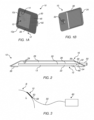
- a transducer 10 comprises a low profile apparatus that is configured to noninvasively sense an indicator of an internal temperature within a portion of a body of a subject.
- the transducer 10 may include a sensor 20 and a communication element 50 for conveying signals from the sensor 20 to an external monitor 60 ( see FIG. 3 ).
- a housing 30 of the transducer 10 may carry the sensor 20.
- the transducer 10 includes a contact side 12 and an outside 16.
- the contact side 12 of the transducer 10 may be configured to face a location of interest L ( FIG. 3 ) within the body B of a subject, while the outside 16 of the transducer 10 may be configured to face away from the location of interest L.
- the transducer 10 may include a receiving aperture 13, through which an indicator of internal temperature, or a native temperature signal S N , may pass, or be transmitted, to the sensor 20.
- the receiving aperture 13 may comprise an opening in the contact side 12 of the transducer 10 or a solid material (e.g ., one or more of a dielectric material, an adhesive material, etc.).
- the sensor 20, which is depicted by FIG. 2 , is configured to receive one or more native temperature signals S N from the location of interest L within the body B of the subject.
- the sensor 20 may include one or more antennas from receiving native temperature signals S N that comprise electromagnetic radiation in the so-called "microwave" portion of the electromagnetic spectrum.
- the range of frequencies of microwave radiation that may be received by the sensor 20 may include native temperature signals S N having frequencies in the range of about 4 GHz ⁇ 200 MHz.
- Specific embodiments of such a sensor 20, which comprise electrically conductive features of a printed circuit board (PCB), are disclosed by PCT International Publication No.
- Such a sensor 20 may receive, and sense, signals that impinge either side-a front side 22 or a back side 26-thereof.
- the front side 22 of the sensor faces the contact side 12 of the transducer 10 and, thus, is located adjacent to the receiving aperture 13.
- the back side 26 of the sensor 20 faces the opposite direction, toward the outside 16 of the transducer 10.
- the front side 22 of the sensor 20 faces the location of interest L, while its back side 26 faces away from the location of interest L.
- a dielectric cavity 28 may be located over, or even directly adjacent to, the back side 26 of the sensor 20.
- the dielectric cavity 28 may provide electrical insulation over the back side 26.
- the dielectric cavity 28 may comprise a dielectric material, which, in some embodiments, may comprise a foam or otherwise include voids ( e.g ., microspheres, microcapsules, etc.; an open-celled material; a close-celled material; etc.).
- the dielectric cavity 28 may comprise a void over the back side 26.
- a void may include a gas (e.g ., an inert gas, such as argon; nitrogen; etc.), a mixture of gases ( e.g ., air, etc.) or a vacuum.
- One or more shielding features 36 of the transducer 10 may be located over the back side 26 of the sensor 20 to prevent interfering signals S X (e.g ., microwaves, etc.) from sources other than the location of interest L from reaching the back side 26 of the sensor 20 and, thus, from interfering with ( e.g ., appearing to the sensor 20 to be) native temperature signals S N from the location of interest L.
- the shielding feature(s) 36 may be positioned over the dielectric cavity 28 or, in embodiments where the dielectric cavity 28 comprises a void, even define a boundary of the dielectric cavity 28.
- the shielding feature(s) 36 may comprise a low resistance electrically conductive material, such as a metal.
- a shielding feature 36 may comprise a film ( e.g ., plating, a deposited film, etc.), a foil or another structure or group of structures.
- shielding features 36 may also be positioned and/or configured to prevent the interfering signals Sx from reaching the front side 22 of the sensor 20.
- the receiving aperture 13, the sensor 20, the dielectric cavity 28 (if any) and the shielding features 36 may be defined by and/or carried by a housing 30 of the transducer 10.
- the transducer 10 may include a housing 30 that carries the sensor 20 and orients and positions the sensor 20 in a manner that will enable the sensor 20 to receive, or sense, native temperature signals S N originating from a location of interest L within the body B of a subject ( FIG. 3 ).
- the housing 30 comprises a rigid structure (e.g ., a structure that is molded, pressed, machined, etc.).
- the housing 30 may comprise a conformal coating (e.g. , a film, such as a shrink-wrap film, a deposited polymeric coating, etc.).
- the housing 30 may define the outside 16 of the transducer 10, toward which the back side 26 of the sensor 20 is oriented.
- the housing 30 may carry the sensor 20 in a manner that orients the front side 22 of the sensor 20 toward the receiving aperture 13 and the contact side 12 of the transducer 10.
- a housing 30 and the back side 26 of the sensor 20 may define the boundaries 29 of the dielectric cavity 28.
- a housing 30 may also define at least a portion of the contact side 12 of the transducer 10.
- the housing 30 may define at least a portion of the receiving aperture 13.
- the housing 30 also carries one or more shielding features 36 of the transducer 10.
- the shielding feature(s) 36 cover(s) the back side 26 of the sensor 20, as well as a periphery 24 of the sensor 20 and a periphery 14 of the receiving aperture 13.
- the shielding feature(s) 36 may be carried by an interior surface 32 of the housing 30.
- the housing 30 may carry one or more shielding features 36 on its exterior surface 34.
- the transducer 10 may also include an adhesive material 38 on at least portions of its contact side 12.
- the adhesive material 38 may be located adjacent to a periphery 12p of the contact side 12 of the transducer10 and surround a more centrally located portion 12c of the contact side 12.
- the adhesive material 38 may comprise or substantially cover the contact side 12 of the transducer 10.
- the adhesive material 38 may form a part of or all of the receiving aperture 13 of the transducer 10.
- the adhesive material 38 may prevent interfering signals Sx from passing between the contact side 12 of the transducer 10 and a surface against which the contact side 12 is positioned and into the receiving aperture 13 of the transducer 10.
- the adhesive material 38 may be configured to secure the transducer 10 in place on or over the body of a subject.
- the transducer 10 may be configured to transmit the intermediate temperature signals to a separate, external monitor 60.
- the transducer 10 may include a communication element 50, which is in communication with the sensor 20 and is configured to communicate with a corresponding element of the external monitor 60.
- the communication element 50 may be configured to couple with an end 56 of a cable 55 in a manner that enables the one or both of the end 56 and the communication element 50 to swivel relative to the other of the communication element 50 and the end 56 of the cable 55.
- the communication element 50 and the end 56 of the cable 50 may comprise coaxial connectors, as depicted by FIGs. 1A through 3 .
- the transducer 10 may also include a reference temperature sensor 45.
- the reference temperature sensor 45 may be configured to obtain a measurement of a reference temperature, such as a temperature of skin at or adjacent to a location where the transducer 10 is positioned on the body B of a subject.
- the reference temperature sensor 45 may comprise a thermistor, a resistance temperature detector (RTD), a thermocouple, an infrared (IR) temperature sensor or the like.
- the transducer 10 may include one or more components (e.g ., circuitry, etc.), which may be carried by the sensor 20 ( e.g ., by a circuit board that defines the sensor, etc.), configured to multiplex intermediate temperature signals and reference temperature signals from the reference temperature sensor 45.
- FIG. 4 a schematic representation of an embodiment of an electrical circuit that enables such multiplexing is depicted. Specifically, FIG. 4 illustrates the sensor 20, a capacitor 25 including a conductor in communication with sensor 20, a reference temperature sensor 45 in communication with an opposite conductor of the capacitor 25, and a communication element 50 ( e.g ., a cable connector, etc.) in series with the reference temperature sensor 45. This arrangement may enable multiplexing of the intermediate temperature signal from the sensor 20 and the reference temperature signal from the reference temperature sensor 45.
- This arrangement may enable multiplexing of the intermediate temperature signal from the sensor 20 and the reference temperature signal from the reference temperature sensor 45.
- the communication element 50 of a transducer 10 may be configured to enable intermediate temperature signals from the sensor 20 to be communicated to a monitor 60, as disclosed previously.
- the communication element 50 may also enable the communication of reference temperature signals to the monitor 60.
- the monitor 60 may include a communication element 62 for receiving signals from the communication element 50 of the transducer 10. Accordingly, the communication element 62 of the monitor 60 may be configured in a manner that complements a configuration of the communication element 50 of the transducer 10. In a non-limiting example, where the communication element 50 comprises a coaxial cable connector and the cable 55 comprises a coaxial cable, the communication element 62 of the monitor 60 may also comprise a coaxial cable connector.
- Signals that are received by the communication element 62 of the monitor 60 are conducted to a first capacitor 64 and to an inductor 68, which are in parallel with one another. Signals that cross the first capacitor 64 are conducted to one or more radiometers 66, which convert each received signal to a voltage. Signals that pass through the inductor 68 are conducted to a thermistor output 70 or to a second capacitor 72, which are in parallel with one another. The second capacitor 72 is connected to a ground 74.
- This arrangement enables demultiplexing of the intermediate temperature signals from the reference temperature signals and, optionally, one or more other signals. More specifically, the first capacitor 64 ensures that only the intermediate temperature signal is conveyed to the radiometer(s) 66, while the second capacitor 72 and ground 74 ensure that only the reference temperature signal is conveyed to the thermistor output 70.
- the monitor 60 may be configured to process the signals in a manner that provides a desired output.
- transducer for noninvasively measuring temperature within a body of a subject, comprising:
- the adhesive material comprises at least a part of the receiving aperture.
- the dielectric cavity comprises a void.
- the dielectric cavity comprises a dielectric material.
- the dielectric cavity includes a plurality of voids dispersed throughout the dielectric material.
- the at least one shielding feature covers the back side of the circuit board and an outer periphery of the circuit board.
- the at least one shielding feature is configured to prevent transmission of interfering signals into the receiving aperture or to the front side of the circuit board.
- the at least one shielding feature comprises a low resistance electrically conductive material.
- the low resistance electrically conductive material comprises a metal.
- the transducer further comprises: a housing that carries or defines the circuit board, the receiving aperture, the dielectric cavity, the adhesive material and the at least one shielding feature.
- an interior surface of the housing carries the at least one shielding feature.
- the transducer further comprises: a reference temperature sensor configured to sense a temperature at a surface over which the transducer is secured.
- transducer for noninvasively measuring temperature within a body of a subject, comprising:
- an end of a cable are configured to swivel relative to one another upon connecting the end of the cable to the cable connector.
- the cable connector comprises a coaxial cable connector.
- the reference temperature sensor comprises a thermistor.
- the circuit board carries at least a portion of an electrical circuit including the antenna, a capacitor and the thermistor, the capacitor being positioned in series between the receiving aperture and the thermistor, the thermistor being in direct communication with the cable connector.
- noninvasive temperature management system comprising:
- the cable comprises a coaxial cable.
Landscapes
- Health & Medical Sciences (AREA)
- Life Sciences & Earth Sciences (AREA)
- Physics & Mathematics (AREA)
- Engineering & Computer Science (AREA)
- Medical Informatics (AREA)
- Animal Behavior & Ethology (AREA)
- Biophysics (AREA)
- Pathology (AREA)
- Biomedical Technology (AREA)
- Heart & Thoracic Surgery (AREA)
- Veterinary Medicine (AREA)
- Molecular Biology (AREA)
- Surgery (AREA)
- Public Health (AREA)
- General Health & Medical Sciences (AREA)
- Computer Networks & Wireless Communication (AREA)
- General Physics & Mathematics (AREA)
- Electromagnetism (AREA)
- Physiology (AREA)
- Nuclear Medicine, Radiotherapy & Molecular Imaging (AREA)
- Radiology & Medical Imaging (AREA)
- Measuring And Recording Apparatus For Diagnosis (AREA)
- Radiation Pyrometers (AREA)
Applications Claiming Priority (3)
| Application Number | Priority Date | Filing Date | Title |
|---|---|---|---|
| US201361883980P | 2013-09-27 | 2013-09-27 | |
| PCT/US2014/057564 WO2015048360A2 (en) | 2013-09-27 | 2014-09-25 | Apparatuses for non-invasively sensing internal temperature |
| EP14847997.5A EP3048958B1 (de) | 2013-09-27 | 2014-09-25 | Vorrichtungen zur nichtinvasiven messung der innentemperatur |
Related Parent Applications (1)
| Application Number | Title | Priority Date | Filing Date |
|---|---|---|---|
| EP14847997.5A Division EP3048958B1 (de) | 2013-09-27 | 2014-09-25 | Vorrichtungen zur nichtinvasiven messung der innentemperatur |
Publications (2)
| Publication Number | Publication Date |
|---|---|
| EP4233701A2 true EP4233701A2 (de) | 2023-08-30 |
| EP4233701A3 EP4233701A3 (de) | 2023-09-20 |
Family
ID=52740155
Family Applications (2)
| Application Number | Title | Priority Date | Filing Date |
|---|---|---|---|
| EP23181677.8A Withdrawn EP4233701A3 (de) | 2013-09-27 | 2014-09-25 | Vorrichtungen zur nichtinvasiven messung der innentemperatur |
| EP14847997.5A Active EP3048958B1 (de) | 2013-09-27 | 2014-09-25 | Vorrichtungen zur nichtinvasiven messung der innentemperatur |
Family Applications After (1)
| Application Number | Title | Priority Date | Filing Date |
|---|---|---|---|
| EP14847997.5A Active EP3048958B1 (de) | 2013-09-27 | 2014-09-25 | Vorrichtungen zur nichtinvasiven messung der innentemperatur |
Country Status (4)
| Country | Link |
|---|---|
| US (1) | US10126180B2 (de) |
| EP (2) | EP4233701A3 (de) |
| JP (1) | JP2016539752A (de) |
| WO (1) | WO2015048360A2 (de) |
Families Citing this family (3)
| Publication number | Priority date | Publication date | Assignee | Title |
|---|---|---|---|---|
| US12285239B2 (en) | 2020-01-21 | 2025-04-29 | Brain Temp, Inc. | Apparatus and method of non-invasively determining deep tissue temperature using microwave radiometry |
| KR20220143845A (ko) * | 2020-01-21 | 2022-10-25 | 브레인 템프, 인크. | 마이크로파 방사 측정을 사용하여 심부 조직 온도를 비침습적으로 측정하는 장치 및 방법 |
| EP4702917A3 (de) * | 2024-08-28 | 2026-05-06 | Brain Temp, Inc. | Vorrichtung zur nichtinvasiven bestimmung der temperatur von tiefen geweben mittels mikrowellenradiometrie |
Citations (1)
| Publication number | Priority date | Publication date | Assignee | Title |
|---|---|---|---|---|
| WO2013090047A2 (en) | 2011-12-13 | 2013-06-20 | Meridian Medical Systems, Llc | Low profile temperature transducer |
Family Cites Families (29)
| Publication number | Priority date | Publication date | Assignee | Title |
|---|---|---|---|---|
| US4346716A (en) * | 1980-03-31 | 1982-08-31 | M/A Com, Inc. | Microwave detection system |
| US4647281A (en) * | 1985-02-20 | 1987-03-03 | M/A-Com, Inc. | Infiltration detection apparatus |
| FR2650390B1 (fr) * | 1989-07-27 | 1992-10-30 | Inst Nat Sante Rech Med | Procede pour la mesure des temperatures par radiometrie microonde, avec calibration automatique de la mesure, et dispositif pour la mise en oeuvre de ce procede |
| US5724030A (en) * | 1994-10-13 | 1998-03-03 | Bio Medic Data Systems, Inc. | System monitoring reprogrammable implantable transponder |
| US5829121A (en) * | 1995-05-08 | 1998-11-03 | Antennas America, Inc. | Antenna making method |
| US6463336B1 (en) * | 1999-04-01 | 2002-10-08 | Mmtc, Inc | Active bandage suitable for applying pulsed radio-frequencies or microwaves to the skin for medical purposes |
| US6511478B1 (en) * | 2000-06-30 | 2003-01-28 | Scimed Life Systems, Inc. | Medical probe with reduced number of temperature sensor wires |
| WO2002089667A1 (en) | 2001-05-03 | 2002-11-14 | Telzuit Technologies, Inc. | Wireless medical monitoring apparatus and system |
| US8328420B2 (en) * | 2003-04-22 | 2012-12-11 | Marcio Marc Abreu | Apparatus and method for measuring biologic parameters |
| KR100485354B1 (ko) | 2002-11-29 | 2005-04-28 | 한국전자통신연구원 | 유전체 덮개를 이용한 마이크로스트립 패치 안테나 및이를 배열한 배열 안테나 |
| US7081096B2 (en) * | 2003-01-24 | 2006-07-25 | Medtronic Vascular, Inc. | Temperature mapping balloon |
| US7484887B2 (en) | 2003-02-20 | 2009-02-03 | Ysis Incorporated | Digitally modified resistive output for a temperature sensor |
| US6932776B2 (en) | 2003-06-02 | 2005-08-23 | Meridian Medicalssystems, Llc | Method and apparatus for detecting and treating vulnerable plaques |
| WO2005004033A2 (en) * | 2003-07-02 | 2005-01-13 | Given Imaging Ltd. | Imaging sensor array and device and method for use thereof |
| US7938783B2 (en) * | 2003-08-19 | 2011-05-10 | Advanced Monitors Corporation | Medical body core thermometer |
| US7304241B2 (en) * | 2004-09-17 | 2007-12-04 | Karl-Heinz Trieb | Swivel connector, cable, and assembly |
| US7124041B1 (en) | 2004-09-27 | 2006-10-17 | Siemens Energy & Automotive, Inc. | Systems, methods, and devices for detecting circuit faults |
| WO2006044700A2 (en) * | 2004-10-13 | 2006-04-27 | Ysi Incorporated | Wireless patch temperature sensor system |
| JP2007305516A (ja) * | 2006-05-15 | 2007-11-22 | Fujitsu Ltd | 同軸コネクタ、コネクタ組立体、プリント基板、及び電子装置 |
| US8062228B2 (en) * | 2007-07-03 | 2011-11-22 | Meridian Medical Systems, Llc | Dual mode intracranial temperature detector |
| US8185341B2 (en) * | 2008-05-30 | 2012-05-22 | Medisim Ltd. | Surface temperature profile |
| US20120057588A1 (en) * | 2009-03-04 | 2012-03-08 | Laird Technologies, Inc. | Multiple antenna multiplexers, demultiplexers and antenna assemblies |
| EP2419939B1 (de) | 2009-04-12 | 2016-03-02 | Ud Holdings, Llc | Infrarot-detektor |
| US8447385B2 (en) * | 2010-07-28 | 2013-05-21 | Welch Allyn, Inc. | Handheld medical microwave radiometer |
| US8714816B2 (en) * | 2010-09-12 | 2014-05-06 | Medisim Ltd. | Temperature sensor with calibrated analog resistive output |
| US8934953B2 (en) * | 2011-05-04 | 2015-01-13 | Meridian Medical Systems, Llc | Dual mode temperature transducer with oxygen saturation sensor |
| WO2013043367A1 (en) * | 2011-09-20 | 2013-03-28 | Micro-Coax, Inc. | Locking connector |
| CN202373800U (zh) | 2011-11-18 | 2012-08-08 | 番禺得意精密电子工业有限公司 | 高频转接器 |
| DE202012010854U1 (de) * | 2012-11-13 | 2012-11-28 | Ondal Medical Systems Gmbh | Koaxialkabel zur elektrischen Übertragung eines Hochfrequenz- und/oder Hochgeschwindigkeits-Datensignals, Drehkupplung mit zwei derartigen Koaxialkabeln, sowie eine Haltevorrichtung mit wenigstens einer solchen Drehkupplung |
-
2014
- 2014-09-25 EP EP23181677.8A patent/EP4233701A3/de not_active Withdrawn
- 2014-09-25 WO PCT/US2014/057564 patent/WO2015048360A2/en not_active Ceased
- 2014-09-25 US US14/497,312 patent/US10126180B2/en active Active
- 2014-09-25 EP EP14847997.5A patent/EP3048958B1/de active Active
- 2014-09-25 JP JP2016545234A patent/JP2016539752A/ja active Pending
Patent Citations (1)
| Publication number | Priority date | Publication date | Assignee | Title |
|---|---|---|---|---|
| WO2013090047A2 (en) | 2011-12-13 | 2013-06-20 | Meridian Medical Systems, Llc | Low profile temperature transducer |
Also Published As
| Publication number | Publication date |
|---|---|
| EP3048958A4 (de) | 2017-05-31 |
| EP3048958A2 (de) | 2016-08-03 |
| US10126180B2 (en) | 2018-11-13 |
| WO2015048360A2 (en) | 2015-04-02 |
| US20150092817A1 (en) | 2015-04-02 |
| EP4233701A3 (de) | 2023-09-20 |
| EP3048958B1 (de) | 2023-06-28 |
| JP2016539752A (ja) | 2016-12-22 |
| WO2015048360A3 (en) | 2015-06-18 |
Similar Documents
| Publication | Publication Date | Title |
|---|---|---|
| US10320063B2 (en) | Methods for slot antenna design for wearable electronic devices and conductive housings | |
| US6563042B2 (en) | Radiating enclosure | |
| US8860613B2 (en) | Patch antenna | |
| US9935362B2 (en) | Systems, apparatuses and methods for biometric sensing using conformal flexible antenna | |
| EP3200278B1 (de) | Antennensystem | |
| US20110025552A1 (en) | High-Frequency Module and Method of Manufacturing the Same, and Transmitter, Receiver, Transceiver, and Radar Apparatus Comprising the High-Frequency Module | |
| CA2499043A1 (en) | Azimuthally focused electromagnetic measurement tool | |
| US10126180B2 (en) | Apparatuses for non-invasively sensing internal temperature | |
| CN110226267B (zh) | 用于将波导连接到至少一个电导体的插头连接器 | |
| US10381722B2 (en) | Tuned grounding arm for near field radio coexistence | |
| JP2004330842A (ja) | タイヤ装着用センサ装置及びセンサ装着タイヤ | |
| EP3554061A1 (de) | Fahrzeuginterne kommunikationsvorrichtung und kommunikationsverfahren | |
| US12087474B2 (en) | Cable and antenna device with coaxial cable | |
| JP2004072320A (ja) | アンテナ装置 | |
| EP2733784B1 (de) | Planare umgedrehte F-Antenne | |
| US10054491B2 (en) | Apparatuses for non-invasively sensing internal temperature | |
| CN210604971U (zh) | 一种平板型双频段探测器的前端系统 | |
| EP3664473B1 (de) | Hörhilfe | |
| US20150048987A1 (en) | Sleeve antenna and wireless communication device | |
| CN205900784U (zh) | 一种移动设备中的4g通讯五模十三频天线 | |
| Roopnarine et al. | Internet of farming: Channel characterization of organic communication channels | |
| CN111103068A (zh) | 温度探测器和温度探测系统 | |
| US20230327423A1 (en) | Connection mechanism of transmission lines | |
| KR101572251B1 (ko) | 잠수함 | |
| KR101113877B1 (ko) | 동축케이블 및 단말기 |
Legal Events
| Date | Code | Title | Description |
|---|---|---|---|
| PUAI | Public reference made under article 153(3) epc to a published international application that has entered the european phase |
Free format text: ORIGINAL CODE: 0009012 |
|
| STAA | Information on the status of an ep patent application or granted ep patent |
Free format text: STATUS: THE APPLICATION HAS BEEN PUBLISHED |
|
| PUAL | Search report despatched |
Free format text: ORIGINAL CODE: 0009013 |
|
| AC | Divisional application: reference to earlier application |
Ref document number: 3048958 Country of ref document: EP Kind code of ref document: P |
|
| AK | Designated contracting states |
Kind code of ref document: A2 Designated state(s): AL AT BE BG CH CY CZ DE DK EE ES FI FR GB GR HR HU IE IS IT LI LT LU LV MC MK MT NL NO PL PT RO RS SE SI SK SM TR |
|
| AK | Designated contracting states |
Kind code of ref document: A3 Designated state(s): AL AT BE BG CH CY CZ DE DK EE ES FI FR GB GR HR HU IE IS IT LI LT LU LV MC MK MT NL NO PL PT RO RS SE SI SK SM TR |
|
| RIC1 | Information provided on ipc code assigned before grant |
Ipc: A61B 5/05 20210101ALI20230814BHEP Ipc: A61B 5/01 20060101AFI20230814BHEP |
|
| STAA | Information on the status of an ep patent application or granted ep patent |
Free format text: STATUS: REQUEST FOR EXAMINATION WAS MADE |
|
| 17P | Request for examination filed |
Effective date: 20240312 |
|
| RBV | Designated contracting states (corrected) |
Designated state(s): AL AT BE BG CH CY CZ DE DK EE ES FI FR GB GR HR HU IE IS IT LI LT LU LV MC MK MT NL NO PL PT RO RS SE SI SK SM TR |
|
| STAA | Information on the status of an ep patent application or granted ep patent |
Free format text: STATUS: EXAMINATION IS IN PROGRESS |
|
| 17Q | First examination report despatched |
Effective date: 20250624 |
|
| STAA | Information on the status of an ep patent application or granted ep patent |
Free format text: STATUS: THE APPLICATION IS DEEMED TO BE WITHDRAWN |
|
| 18D | Application deemed to be withdrawn |
Effective date: 20251025 |