EP4233218B1 - Decodierung von kanalstatusinformationsberichtsteil zwei - Google Patents
Decodierung von kanalstatusinformationsberichtsteil zwei Download PDFInfo
- Publication number
- EP4233218B1 EP4233218B1 EP20800327.7A EP20800327A EP4233218B1 EP 4233218 B1 EP4233218 B1 EP 4233218B1 EP 20800327 A EP20800327 A EP 20800327A EP 4233218 B1 EP4233218 B1 EP 4233218B1
- Authority
- EP
- European Patent Office
- Prior art keywords
- pusch
- csi
- csi report
- scrambling sequence
- report part
- Prior art date
- Legal status (The legal status is an assumption and is not a legal conclusion. Google has not performed a legal analysis and makes no representation as to the accuracy of the status listed.)
- Active
Links
Images
Classifications
-
- H—ELECTRICITY
- H04—ELECTRIC COMMUNICATION TECHNIQUE
- H04L—TRANSMISSION OF DIGITAL INFORMATION, e.g. TELEGRAPHIC COMMUNICATION
- H04L1/00—Arrangements for detecting or preventing errors in the information received
- H04L1/0001—Systems modifying transmission characteristics according to link quality, e.g. power backoff
- H04L1/0023—Systems modifying transmission characteristics according to link quality, e.g. power backoff characterised by the signalling
- H04L1/0026—Transmission of channel quality indication
-
- H—ELECTRICITY
- H04—ELECTRIC COMMUNICATION TECHNIQUE
- H04W—WIRELESS COMMUNICATION NETWORKS
- H04W72/00—Local resource management
- H04W72/12—Wireless traffic scheduling
- H04W72/1263—Mapping of traffic onto schedule, e.g. scheduled allocation or multiplexing of flows
- H04W72/1268—Mapping of traffic onto schedule, e.g. scheduled allocation or multiplexing of flows of uplink data flows
-
- H—ELECTRICITY
- H04—ELECTRIC COMMUNICATION TECHNIQUE
- H04L—TRANSMISSION OF DIGITAL INFORMATION, e.g. TELEGRAPHIC COMMUNICATION
- H04L1/00—Arrangements for detecting or preventing errors in the information received
- H04L1/0001—Systems modifying transmission characteristics according to link quality, e.g. power backoff
- H04L1/0036—Systems modifying transmission characteristics according to link quality, e.g. power backoff arrangements specific to the receiver
- H04L1/0038—Blind format detection
-
- H—ELECTRICITY
- H04—ELECTRIC COMMUNICATION TECHNIQUE
- H04L—TRANSMISSION OF DIGITAL INFORMATION, e.g. TELEGRAPHIC COMMUNICATION
- H04L1/00—Arrangements for detecting or preventing errors in the information received
- H04L1/004—Arrangements for detecting or preventing errors in the information received by using forward error control
- H04L1/0072—Error control for data other than payload data, e.g. control data
-
- H—ELECTRICITY
- H04—ELECTRIC COMMUNICATION TECHNIQUE
- H04L—TRANSMISSION OF DIGITAL INFORMATION, e.g. TELEGRAPHIC COMMUNICATION
- H04L1/00—Arrangements for detecting or preventing errors in the information received
- H04L1/12—Arrangements for detecting or preventing errors in the information received by using return channel
- H04L1/16—Arrangements for detecting or preventing errors in the information received by using return channel in which the return channel carries supervisory signals, e.g. repetition request signals
- H04L1/18—Automatic repetition systems, e.g. Van Duuren systems
- H04L1/1867—Arrangements specially adapted for the transmitter end
- H04L1/1887—Scheduling and prioritising arrangements
-
- H—ELECTRICITY
- H04—ELECTRIC COMMUNICATION TECHNIQUE
- H04W—WIRELESS COMMUNICATION NETWORKS
- H04W72/00—Local resource management
- H04W72/20—Control channels or signalling for resource management
- H04W72/21—Control channels or signalling for resource management in the uplink direction of a wireless link, i.e. towards the network
Definitions
- Embodiments of the present disclosure are directed to wireless communications and, more particularly, to efficiently decoding one or two bits of channel state information (CSI) report part two in fifth generation (5G) new radio (NR).
- CSI channel state information
- 5G fifth generation new radio
- MIMO multiple-input multiple-output
- Channel state information (CSI) at the network side is indispensable to fully take advantage of the potential of such complex multiple antenna techniques.
- CSI-RS CSI reference signal
- NR Similar to LTE, NR also uses CSI-RS for CSI acquisition, but NR defines a highly flexible but unified CSI framework that reduces the coupling between CSI measurement, CSI reporting, and the actual downlink transmission compared with LTE.
- the CSI framework may be represented as a pool where different CSI report settings and CSI-RS resource settings for channel and interference measurement can be mixed and matched, so that they correspond to the antenna deployment and transmission scheme in use, and where CSI reports on different beams can be dynamically triggered.
- each CSI resource setting contains one or several CSI resource sets, with each CSI resource set consisting of one or several CSI-RS resources.
- CSI-RS are defined in Third Generation Partnership Project (3GPP) Technical Specification (TS) 38.211 Clause 7.4.1.5.2 and 7.4.1.5.3 for sequence generation and physical resources mapping.
- a UE may be configured with one or more CSI resource settings for channel and interference measurement.
- CSI report format i.e. the frequency granularity of channel quality indicator (CQI) and precoding matrix indicator (PMI)
- CQI channel quality indicator
- PMI precoding matrix indicator
- UE user equipment
- RRC radio resource control
- It may be a combination of wideband/subband CQI and wideband/subband PMI.
- NR provides the ability to configure multiple CSI report configurations with different CSI report formats, while the downlink control information (DCI) for each scheduling assignment only triggers one configuration.
- DCI downlink control information
- subband CQI/PMI provides better performance than wideband CQI/PMI.
- the payload size of subband CSI in NR is a restricted factor from link budget perspective.
- Subband report could be set as default for better downlink performance. If uplink coverage is limited, switching back to wideband is necessary.
- a UE When wideband PMI is configured, a UE will report wideband PMI index ii and wideband PMI index i 2 . When subband PMI is configured, a UE will report wideband PMI index ii together with subband PMI index i 2 .
- the aperiodic CSI request is sent to the UE by an uplink physical uplink shared channel (PUSCH) scheduling grant with a special field indicating that A-CSI report is requested.
- PUSCH physical uplink shared channel
- Each CSI reporting includes two parts, CSI part 1 and CSI part 2.
- CSI part 1 includes CSI resource indicator (CSI-RS), rank indicator (RI), wideband CQI, and subband CQI, if subband CQI is reported.
- CSI part 2 includes wideband PMI in, i 12 , i 13 , wideband PMI i 2 , if wideband PMI is reported, and sub-band PMI i 2 , if sub-band PMI is reported.
- the CSI payload size of each part for wideband and sub-band reports for 32 ports are given in Table 1 and Table 2, respectively.
- the payload size in the table is only given for each sub-band.
- the total size of payload depends on the channel bandwidth and sub-band size. For sub-band sizes and the number of sub-bands corresponding to each channel bandwidth, refer to Table 3.
- Uplink control information is transmitted on PUSCH when an uplink PUSCH scheduling grant is received by the UE. It contains CSI report part 1 and 2 and downlink transmission hybrid automatic repeat request (HARQ) feedbacks.
- HARQ downlink transmission hybrid automatic repeat request
- CSI report part 1 contains the channel quality information
- CSI report part 2 contains the PMI index information. They are encoded independently.
- RI 1 (One layer)
- RI 2 (Two layers)
- PMI Index PMI Matrix
- PMI Matrix 0 1 2 1 1 1 0 1 2 1 1 1 1 ⁇ 1 1 1 2 1 j 1 1 2 1 1 1 1 ⁇ 1 2 1 2 1 ⁇ 1 3 1 2 1 ⁇ j
- N Q m
- Q m is the modulation order
- c 0 is one information bit
- x and y (x ⁇ y) are placeholders to scramble the information bits in a way that maximizes the Euclidean distance of the modulation symbols carrying the information bits. In the product implementation, they can be represented by the arbitrarily chosen values which are not equal to either 0 or 1.
- Scrambling may be performed as follows.
- the single codeword q 0, the block of bits b q 0 ,... , b q M bit q ⁇ 1 , where M bit q is the number of bits in codeword q transmitted on the physical channel, shall be scrambled prior to modulation, resulting in a block of scrambled bits b ⁇ q 0 ,... , b ⁇ q M bit q ⁇ 1 according to the following pseudo code
- the scrambling sequence c ( q ) ( i ) is given by Section 5.2.1 of 38.211.
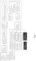
- FIGURE 1 An example is illustrated in FIGURE 1 .
- FIGURE 1 is a flow diagram illustrating dependency and chaining of functional blocks for UCI and PUSCH data decoding.
- PUSCH allocation time about 1 slot earlier than the airlink time
- the soft bit locations for downlink HARQ soft bits and CSI report part 1 soft bits are calculated and the scrambling sequence is generated.
- Downlink HARQ 1 or 2 bits are reserved and puncture CSI part 2 soft bits or data soft bits according to 3GPP NR specifications; but CSI part 2 scrambling bits cannot be corrected based on x and y location because the number of soft values and their location are unknown until after CSI part 1 decoding.
- CSI report part 2 and data soft locations are not known at this time.
- the process must wait until CSI part 1 has been demultiplexed and decoded to find the correct rank indicator.
- CSI part 2 and data are conditioned on the decoded rank indicator.
- the process cannot prepare for the x and y location treatment of the scrambling sequence at allocation time as for downlink 1 or 2 bit HARQ.
- a method of a UE includes receiving a configuration for a number of hybrid automatic repeat request acknowledgement (HARQ-ACK) information bits per data transport block (TB); receiving a downlink control information (DCI) format scheduling a reception of a data TB; and receiving the data TB that includes a number of data code blocks (CBs).
- the method further includes determining a number of HARQ-ACK information bits for a respective number of CB groups (CBGs); determining CBs per CBG; generating HARQ-ACK information bits; and generating a HARQ-ACK codeword. Additionally, the method includes transmitting the HARQ-ACK codeword in a physical uplink control channel (PUCCH) or in a PUSCH.
- PUCCH physical uplink control channel
- CSI channel state information
- 5G fifth generation new radio
- Certain aspects of the present disclosure and their embodiments may provide solutions to these or other challenges. For example, particular embodiments efficiently decode 1 or 2 bits CSI part 2 with two CSI RS ports. Because at the beginning of the decoding process, the exact locations of CSI report part 2 soft bits is unknown, particular embodiments treat them as the normal data soft bits when generating the descrambling sequence and perform the descrambling process for all the input soft bits which may include both UCI and data soft bits.
- the UCI may contain downlink HARQ feedbacks plus CSI report part 1 and 2.
- the rank information is known, and particular embodiments are able to locate the positions of CSI report part 2 bits. Based on the known soft value locations for CSI part 2, particular embodiments extract the scrambling sequence from the total scrambling sequence. Particular embodiments apply the extracted CSI part 2 scrambling sequence to the extracted CSI part 2 soft values. This is equivalent to undoing what was done before for the CSI part 2 soft values.
- particular embodiments reproduce the correct CSI part 2 scrambling sequence and apply it to the extracted CSI part 2 soft values.
- the 1 or 2 bits of CSI report part 2 can be decoded.
- a method performed by a network node for decoding a CSI report comprises generating a PUSCH scrambling sequence for descrambling a PUSCH without accounting for the existence of a CSI report part two and receiving the PUSCH from a wireless device.
- the PUSCH comprises a CSI report part one and a CSI report part two.
- the method further comprises descrambling the PUSCH using the PUSCH scrambling sequence, decoding the CSI report part one from the descrambled PUSCH to determine a rank indicator, and determining a location of CSI report part two soft bits in the PUSCH based on the rank indicator.
- the method further comprises extracting a scrambling sequence from the PUSCH scrambling sequence corresponding to the location of the CSI report part two in the PUSCH, generating a CSI part two scrambling sequence based on the PUSCH scrambling sequence and the location of the CSI report part two in the PUSCH with correct x and y locations, and applying the extracted scrambling sequence to the location of the CSI report part two soft bits in the PUSCH to undo the incorrect scrambling.
- the method further comprises descrambling the location of the CSI report part two soft bits in the PUSCH using the CSI part two scrambling sequence and decoding the CSI part two.
- the decoding of the CSI part two is performed without delaying the decoding of CSI part one or hybrid automatic repeat request (HARQ) feedback.
- HARQ hybrid automatic repeat request
- the CSI report part two is either one bit or two bits.
- the PUSCH further comprises 1 or 2 bits hybrid automatic repeat request (HARQ) feedback and the PUSCH scrambling sequence accounts for the 1 or 2 bits HARQ feedback.
- the PUSCH may further comprise data.
- a network node for decoding a CSI report comprises processing circuitry configured to perform any of the network node methods described above.
- a computer program product comprising a non-transitory computer readable medium storing computer readable program code
- the computer readable program code being operable, when executed by processing circuitry to perform any of the methods performed by the network node described above.
- Certain embodiments may provide one or more of the following technical advantages. For example, particular embodiments decode CSI part two without impacting total latency and memory. Particular embodiments decode CSI part two without impacting latency for downlink HARQ and CSI part one decoding latency, which are critical.
- particular embodiments break the interdependencies between the function blocks illustrated in FIGURE 1 and localize the impact to CSI part two decoding. Particular embodiments save about 1 slot processing time and CM and EM buffers for uplink HARQ and data decoding. Some embodiments save 1 slot processing time for CSI part one decoding and save 1 slot processing time for downlink HARQ feedback decoding.
- Particular embodiments do not significantly impact the CSI part two decoding because the number of CSI part two soft bits is small for 1 or 2 CSI part two information bits, usually just for a few resource elements (REs) depending on modulation order. The higher the order, the fewer the number of REs.
- REs resource elements
- CSI channel state information
- 5G fifth generation new radio
- UCI uplink control information
- PUSCH physical uplink shared channel
- particular embodiments locate the positions of CSI report part two soft bits and based on their positions, extract the scrambling sequence from the total scrambling sequence.
- the extracted CSI part two scrambling sequence is applied to the extracted CSI part two soft values to reproduce the correct CSI part two scrambling sequence and apply it to the extracted CSI part two soft values.
- Step 1 To avoid duplicating the processing chains from Step 1 to Step 3 shown in FIGURE 1 , particular embodiments recover the original CSI part two soft values and apply the punctured scrambling sequence after Step 3.
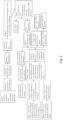
- An example is illustrated in FIGURE 2 .
- FIGURE 2 is a flow diagram illustrating functional blocks for effectively decoding 1or 2 bits CSI report part two, according to a particular embodiment.
- the PUSCH scrambling sequence is generated and special treatment for x and y locations is also done if the PUSCH has 1 or 2 bits downlink HARQ.
- the x and y location treatment for CSI part two cannot be performed because the number of CSI part 2 soft values is not yet known.
- the information is known only after CSI report part one decoding to get the rank information.
- step 1 at demodulation time, parallel threads may be launched to produce chunks of soft values, and they are in digital signal processor (DSP) local data memory (LDM) cache.
- DSP digital signal processor
- LDM local data memory
- the descrambling is performed based on the sequence generated at step 0, x and y location treatment for downlink HARQ 1 or 2 bit is taken care of.
- the CSI part 2 x and y location treatment cannot be performed when generating the descrambling sequence because the rank information is not available in this step. Otherwise, some solutions would have to do several copies of demodulation soft values to cover all rank possibilities, which is difficult due to memory, CPU cycles, and latency limitations.
- step 2 demultiplexing CSI part one and downlink HARQ results in CSI part one and downlink HARQ soft values and the leftover soft values for CSI part two and data.
- the 1 or 2 bits HARQ soft values puncturing on CSI part two and data soft values are done at the end of this step.
- the rank information is known and thus particular embodiments perform rate de-matching for CSI part two and data.
- the number of CSI part two soft values and how many data soft values is known and particular embodiments perform demultiplexing to know their specific locations in the total soft values for PUSCH.
- step 4 based on the known soft value locations from step 3 for CSI part two, particular embodiments extract the scrambling sequence from the total scrambling sequence.
- step 5 particular embodiments apply the extracted CSI part two scrambling sequence from step 4 to the extracted CSI part two soft values from step 3. This is equivalent to undo what was done in step 1 for the CSI part two soft values, because it is not correct for those particular soft values.
- the soft values for CSI part two are recovered to their original values.
- the CSI part 2 x and y locations are known from step 3 and particular embodiments apply the x and y location treatment based on the extracted CSI part two scrambling sequence from step 4 to produce the correct CSI part two scrambling sequence.
- step 7 particular embodiments apply the CSI part two correct scrambling sequence from step 6 to the recovered original CSI part two soft values from step 5 to produce the correct de-scrambled CSI part two soft values.
- step 8 particular embodiments use the correctly scrambled CSI part two soft values from step 7 and perform rate de-matching.
- the rate matched soft values are used for 1 or 2 bits decoding and produce 1 or 2 bits decoded values.
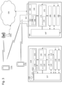
- FIGURE 3 illustrates an example wireless network, according to certain embodiments.
- the wireless network may comprise and/or interface with any type of communication, telecommunication, data, cellular, and/or radio network or other similar type of system.
- the wireless network may be configured to operate according to specific standards or other types of predefined rules or procedures.
- wireless network may implement communication standards, such as Global System for Mobile Communications (GSM), Universal Mobile Telecommunications System (UMTS), Long Term Evolution (LTE), and/or other suitable 2G, 3G, 4G, or 5G standards; wireless local area network (WLAN) standards, such as the IEEE 802.11 standards; and/or any other appropriate wireless communication standard, such as the Worldwide Interoperability for Microwave Access (WiMax), Bluetooth, Z-Wave and/or ZigBee standards.
- GSM Global System for Mobile Communications
- UMTS Universal Mobile Telecommunications System
- LTE Long Term Evolution
- WLAN wireless local area network
- WiMax Worldwide Interoperability for Microwave Access
- Bluetooth Z-Wave and/or ZigBee standards.
- Network 106 may comprise one or more backhaul networks, core networks, IP networks, public switched telephone networks (PSTNs), packet data networks, optical networks, wide-area networks (WANs), local area networks (LANs), wireless local area networks (WLANs), wired networks, wireless networks, metropolitan area networks, and other networks to enable communication between devices.
- PSTNs public switched telephone networks
- WANs wide-area networks
- LANs local area networks
- WLANs wireless local area networks
- wired networks wireless networks, metropolitan area networks, and other networks to enable communication between devices.
- Network node 160 and WD 110 comprise various components described in more detail below. These components work together to provide network node and/or wireless device functionality, such as providing wireless connections in a wireless network.
- the wireless network may comprise any number of wired or wireless networks, network nodes, base stations, controllers, wireless devices, relay stations, and/or any other components or systems that may facilitate or participate in the communication of data and/or signals whether via wired or wireless connections.
- network node refers to equipment capable, configured, arranged and/or operable to communicate directly or indirectly with a wireless device and/or with other network nodes or equipment in the wireless network to enable and/or provide wireless access to the wireless device and/or to perform other functions (e.g., administration) in the wireless network.
- network nodes include, but are not limited to, access points (APs) (e.g., radio access points), base stations (BSs) (e.g., radio base stations, Node Bs, evolved Node Bs (eNBs) and NR NodeBs (gNBs)).
- APs access points
- BSs base stations
- Node Bs evolved Node Bs
- gNBs NR NodeBs
- Base stations may be categorized based on the amount of coverage they provide (or, stated differently, their transmit power level) and may then also be referred to as femto base stations, pico base stations, micro base stations, or macro base stations.
- a base station may be a relay node or a relay donor node controlling a relay.
- a network node may also include one or more (or all) parts of a distributed radio base station such as centralized digital units and/or remote radio units (RRUs), sometimes referred to as Remote Radio Heads (RRHs).
- RRUs remote radio units
- RRHs Remote Radio Heads
- Such remote radio units may or may not be integrated with an antenna as an antenna integrated radio.
- Parts of a distributed radio base station may also be referred to as nodes in a distributed antenna system (DAS).
- DAS distributed antenna system
- network nodes include multi-standard radio (MSR) equipment such as MSR BSs, network controllers such as radio network controllers (RNCs) or base station controllers (BSCs), base transceiver stations (BTSs), transmission points, transmission nodes, multi-cell/multicast coordination entities (MCEs), core network nodes (e.g., MSCs, MMEs), O&M nodes, OSS nodes, SON nodes, positioning nodes (e.g., E-SMLCs), and/or MDTs.
- MSR multi-standard radio
- RNCs radio network controllers
- BSCs base station controllers
- BTSs base transceiver stations
- MCEs multi-cell/multicast coordination entities
- core network nodes e.g., MSCs, MMEs
- O&M nodes e.g., OSS nodes
- SON nodes e.g., SON nodes
- positioning nodes e.g., E-SMLCs
- a network node may be a virtual network node as described in more detail below. More generally, however, network nodes may represent any suitable device (or group of devices) capable, configured, arranged, and/or operable to enable and/or provide a wireless device with access to the wireless network or to provide some service to a wireless device that has accessed the wireless network.
- network node 160 includes processing circuitry 170, device readable medium 180, interface 190, auxiliary equipment 184, power source 186, power circuitry 187, and antenna 162.
- network node 160 illustrated in the example wireless network of FIGURE 3 may represent a device that includes the illustrated combination of hardware components, other embodiments may comprise network nodes with different combinations of components.
- a network node comprises any suitable combination of hardware and/or software needed to perform the tasks, features, functions and methods disclosed herein.
- components of network node 160 are depicted as single boxes located within a larger box, or nested within multiple boxes, in practice, a network node may comprise multiple different physical components that make up a single illustrated component (e.g., device readable medium 180 may comprise multiple separate hard drives as well as multiple RAM modules).
- network node 160 may be composed of multiple physically separate components (e.g., a NodeB component and a RNC component, or a BTS component and a BSC component, etc.), which may each have their own respective components.
- network node 160 comprises multiple separate components (e.g., BTS and BSC components)
- one or more of the separate components may be shared among several network nodes.
- a single RNC may control multiple NodeB's.
- each unique NodeB and RNC pair may in some instances be considered a single separate network node.
- network node 160 may be configured to support multiple radio access technologies (RATs). In such embodiments, some components may be duplicated (e.g., separate device readable medium 180 for the different RATs) and some components may be reused (e.g., the same antenna 162 may be shared by the RATs).
- Network node 160 may also include multiple sets of the various illustrated components for different wireless technologies integrated into network node 160, such as, for example, GSM, WCDMA, LTE, NR, WiFi, or Bluetooth wireless technologies. These wireless technologies may be integrated into the same or different chip or set of chips and other components within network node 160.
- Processing circuitry 170 is configured to perform any determining, calculating, or similar operations (e.g., certain obtaining operations) described herein as being provided by a network node. These operations performed by processing circuitry 170 may include processing information obtained by processing circuitry 170 by, for example, converting the obtained information into other information, comparing the obtained information or converted information to information stored in the network node, and/or performing one or more operations based on the obtained information or converted information, and as a result of said processing making a determination.
- processing information obtained by processing circuitry 170 by, for example, converting the obtained information into other information, comparing the obtained information or converted information to information stored in the network node, and/or performing one or more operations based on the obtained information or converted information, and as a result of said processing making a determination.
- Processing circuitry 170 may comprise a combination of one or more of a microprocessor, controller, microcontroller, central processing unit, digital signal processor, application-specific integrated circuit, field programmable gate array, or any other suitable computing device, resource, or combination of hardware, software and/or encoded logic operable to provide, either alone or in conjunction with other network node 160 components, such as device readable medium 180, network node 160 functionality.
- processing circuitry 170 may execute instructions stored in device readable medium 180 or in memory within processing circuitry 170. Such functionality may include providing any of the various wireless features, functions, or benefits discussed herein.
- processing circuitry 170 may include a system on a chip (SOC).
- processing circuitry 170 may include one or more of radio frequency (RF) transceiver circuitry 172 and baseband processing circuitry 174.
- radio frequency (RF) transceiver circuitry 172 and baseband processing circuitry 174 may be on separate chips (or sets of chips), boards, or units, such as radio units and digital units.
- part or all of RF transceiver circuitry 172 and baseband processing circuitry 174 may be on the same chip or set of chips, boards, or units
- processing circuitry 170 executing instructions stored on device readable medium 180 or memory within processing circuitry 170.
- some or all of the functionality may be provided by processing circuitry 170 without executing instructions stored on a separate or discrete device readable medium, such as in a hard-wired manner.
- processing circuitry 170 can be configured to perform the described functionality. The benefits provided by such functionality are not limited to processing circuitry 170 alone or to other components of network node 160 but are enjoyed by network node 160 as a whole, and/or by end users and the wireless network generally.
- Device readable medium 180 may comprise any form of volatile or non-volatile computer readable memory including, without limitation, persistent storage, solid-state memory, remotely mounted memory, magnetic media, optical media, random access memory (RAM), read-only memory (ROM), mass storage media (for example, a hard disk), removable storage media (for example, a flash drive, a Compact Disk (CD) or a Digital Video Disk (DVD)), and/or any other volatile or non-volatile, non-transitory device readable and/or computer-executable memory devices that store information, data, and/or instructions that may be used by processing circuitry 170.
- volatile or non-volatile computer readable memory including, without limitation, persistent storage, solid-state memory, remotely mounted memory, magnetic media, optical media, random access memory (RAM), read-only memory (ROM), mass storage media (for example, a hard disk), removable storage media (for example, a flash drive, a Compact Disk (CD) or a Digital Video Disk (DVD)), and/or any other volatile or non
- Device readable medium 180 may store any suitable instructions, data or information, including a computer program, software, an application including one or more of logic, rules, code, tables, etc. and/or other instructions capable of being executed by processing circuitry 170 and, utilized by network node 160.
- Device readable medium 180 may be used to store any calculations made by processing circuitry 170 and/or any data received via interface 190.
- processing circuitry 170 and device readable medium 180 may be considered to be integrated.
- Interface 190 is used in the wired or wireless communication of signaling and/or data between network node 160, network 106, and/or WDs 110. As illustrated, interface 190 comprises port(s)/terminal(s) 194 to send and receive data, for example to and from network 106 over a wired connection. Interface 190 also includes radio front end circuitry 192 that may be coupled to, or in certain embodiments a part of, antenna 162.
- Radio front end circuitry 192 comprises filters 198 and amplifiers 196.
- Radio front end circuitry 192 may be connected to antenna 162 and processing circuitry 170. Radio front end circuitry may be configured to condition signals communicated between antenna 162 and processing circuitry 170.
- Radio front end circuitry 192 may receive digital data that is to be sent out to other network nodes or WDs via a wireless connection. Radio front end circuitry 192 may convert the digital data into a radio signal having the appropriate channel and bandwidth parameters using a combination of filters 198 and/or amplifiers 196. The radio signal may then be transmitted via antenna 162.
- antenna 162 may collect radio signals which are then converted into digital data by radio front end circuitry 192.
- the digital data may be passed to processing circuitry 170.
- the interface may comprise different components and/or different combinations of components.
- network node 160 may not include separate radio front end circuitry 192, instead, processing circuitry 170 may comprise radio front end circuitry and may be connected to antenna 162 without separate radio front end circuitry 192.
- processing circuitry 170 may comprise radio front end circuitry and may be connected to antenna 162 without separate radio front end circuitry 192.
- all or some of RF transceiver circuitry 172 may be considered a part of interface 190.
- interface 190 may include one or more ports or terminals 194, radio front end circuitry 192, and RF transceiver circuitry 172, as part of a radio unit (not shown), and interface 190 may communicate with baseband processing circuitry 174, which is part of a digital unit (not shown).
- Antenna 162 may include one or more antennas, or antenna arrays, configured to send and/or receive wireless signals. Antenna 162 may be coupled to radio front end circuitry 192 and may be any type of antenna capable of transmitting and receiving data and/or signals wirelessly. In some embodiments, antenna 162 may comprise one or more omni-directional, sector or panel antennas operable to transmit/receive radio signals between, for example, 2 GHz and 66 GHz. An omni-directional antenna may be used to transmit/receive radio signals in any direction, a sector antenna may be used to transmit/receive radio signals from devices within a particular area, and a panel antenna may be a line of sight antenna used to transmit/receive radio signals in a relatively straight line. In some instances, the use of more than one antenna may be referred to as MIMO. In certain embodiments, antenna 162 may be separate from network node 160 and may be connectable to network node 160 through an interface or port.
- Antenna 162, interface 190, and/or processing circuitry 170 may be configured to perform any receiving operations and/or certain obtaining operations described herein as being performed by a network node. Any information, data and/or signals may be received from a wireless device, another network node and/or any other network equipment. Similarly, antenna 162, interface 190, and/or processing circuitry 170 may be configured to perform any transmitting operations described herein as being performed by a network node. Any information, data and/or signals may be transmitted to a wireless device, another network node and/or any other network equipment.
- Power circuitry 187 may comprise, or be coupled to, power management circuitry and is configured to supply the components of network node 160 with power for performing the functionality described herein. Power circuitry 187 may receive power from power source 186. Power source 186 and/or power circuitry 187 may be configured to provide power to the various components of network node 160 in a form suitable for the respective components (e.g., at a voltage and current level needed for each respective component). Power source 186 may either be included in, or external to, power circuitry 187 and/or network node 160.
- network node 160 may be connectable to an external power source (e.g., an electricity outlet) via an input circuitry or interface such as an electrical cable, whereby the external power source supplies power to power circuitry 187.
- power source 186 may comprise a source of power in the form of a battery or battery pack which is connected to, or integrated in, power circuitry 187. The battery may provide backup power should the external power source fail.
- Other types of power sources such as photovoltaic devices, may also be used.
- network node 160 may include additional components beyond those shown in FIGURE 3 that may be responsible for providing certain aspects of the network node's functionality, including any of the functionality described herein and/or any functionality necessary to support the subject matter described herein.
- network node 160 may include user interface equipment to allow input of information into network node 160 and to allow output of information from network node 160. This may allow a user to perform diagnostic, maintenance, repair, and other administrative functions for network node 160.
- wireless device refers to a device capable, configured, arranged and/or operable to communicate wirelessly with network nodes and/or other wireless devices. Unless otherwise noted, the term WD may be used interchangeably herein with user equipment (UE). Communicating wirelessly may involve transmitting and/or receiving wireless signals using electromagnetic waves, radio waves, infrared waves, and/or other types of signals suitable for conveying information through air.
- a WD may be configured to transmit and/or receive information without direct human interaction.
- a WD may be designed to transmit information to a network on a predetermined schedule, when triggered by an internal or external event, or in response to requests from the network.
- Examples of a WD include, but are not limited to, a smart phone, a mobile phone, a cell phone, a voice over IP (VoIP) phone, a wireless local loop phone, a desktop computer, a personal digital assistant (PDA), a wireless cameras, a gaming console or device, a music storage device, a playback appliance, a wearable terminal device, a wireless endpoint, a mobile station, a tablet, a laptop, a laptop-embedded equipment (LEE), a laptop-mounted equipment (LME), a smart device, a wireless customer-premise equipment (CPE). a vehicle-mounted wireless terminal device, etc.
- VoIP voice over IP
- PDA personal digital assistant
- PDA personal digital assistant
- gaming console or device a wireless cameras
- a gaming console or device a music storage device
- a playback appliance a wearable terminal device
- a wireless endpoint a mobile station, a tablet, a laptop, a laptop-embedded equipment (LEE), a laptop
- a WD may support device-to-device (D2D) communication, for example by implementing a 3GPP standard for sidelink communication, vehicle-to-vehicle (V2V), vehicle-to-infrastructure (V2I), vehicle-to-everything (V2X) and may in this case be referred to as a D2D communication device.
- D2D device-to-device
- a WD may represent a machine or other device that performs monitoring and/or measurements and transmits the results of such monitoring and/or measurements to another WD and/or a network node.
- the WD may in this case be a machine-to-machine (M2M) device, which may in a 3GPP context be referred to as an MTC device.
- M2M machine-to-machine
- the WD may be a UE implementing the 3GPP narrow band internet of things (NB-IoT) standard.
- NB-IoT narrow band internet of things
- machines or devices are sensors, metering devices such as power meters, industrial machinery, or home or personal appliances (e.g. refrigerators, televisions, etc.) personal wearables (e.g., watches, fitness trackers, etc.).
- a WD may represent a vehicle or other equipment that is capable of monitoring and/or reporting on its operational status or other functions associated with its operation.
- a WD as described above may represent the endpoint of a wireless connection, in which case the device may be referred to as a wireless terminal.
- a WD as described above may be mobile, in which case it may also be referred to as a mobile device or a mobile terminal.
- wireless device 110 includes antenna 111, interface 114, processing circuitry 120, device readable medium 130, user interface equipment 132, auxiliary equipment 134, power source 136 and power circuitry 137.
- WD 110 may include multiple sets of one or more of the illustrated components for different wireless technologies supported by WD 110, such as, for example, GSM, WCDMA, LTE, NR, WiFi, WiMAX, or Bluetooth wireless technologies, just to mention a few. These wireless technologies may be integrated into the same or different chips or set of chips as other components within WD 110.
- Antenna 111 may include one or more antennas or antenna arrays, configured to send and/or receive wireless signals, and is connected to interface 114. In certain alternative embodiments, antenna 111 may be separate from WD 110 and be connectable to WD 110 through an interface or port. Antenna 111, interface 114, and/or processing circuitry 120 may be configured to perform any receiving or transmitting operations described herein as being performed by a WD. Any information, data and/or signals may be received from a network node and/or another WD. In some embodiments, radio front end circuitry and/or antenna 111 may be considered an interface.
- interface 114 comprises radio front end circuitry 112 and antenna 111.
- Radio front end circuitry 112 comprise one or more filters 118 and amplifiers 116.
- Radio front end circuitry 112 is connected to antenna 111 and processing circuitry 120 and is configured to condition signals communicated between antenna 111 and processing circuitry 120.
- Radio front end circuitry 112 may be coupled to or a part of antenna 111.
- WD 110 may not include separate radio front end circuitry 112; rather, processing circuitry 120 may comprise radio front end circuitry and may be connected to antenna 111.
- some or all of RF transceiver circuitry 122 may be considered a part of interface 114.
- Radio front end circuitry 112 may receive digital data that is to be sent out to other network nodes or WDs via a wireless connection. Radio front end circuitry 112 may convert the digital data into a radio signal having the appropriate channel and bandwidth parameters using a combination of filters 118 and/or amplifiers 116. The radio signal may then be transmitted via antenna 111. Similarly, when receiving data, antenna 111 may collect radio signals which are then converted into digital data by radio front end circuitry 112. The digital data may be passed to processing circuitry 120. In other embodiments, the interface may comprise different components and/or different combinations of components.
- Processing circuitry 120 may comprise a combination of one or more of a microprocessor, controller, microcontroller, central processing unit, digital signal processor, application-specific integrated circuit, field programmable gate array, or any other suitable computing device, resource, or combination of hardware, software, and/or encoded logic operable to provide, either alone or in conjunction with other WD 110 components, such as device readable medium 130, WD 110 functionality. Such functionality may include providing any of the various wireless features or benefits discussed herein. For example, processing circuitry 120 may execute instructions stored in device readable medium 130 or in memory within processing circuitry 120 to provide the functionality disclosed herein.
- processing circuitry 120 includes one or more of RF transceiver circuitry 122, baseband processing circuitry 124, and application processing circuitry 126.
- the processing circuitry may comprise different components and/or different combinations of components.
- processing circuitry 120 of WD 110 may comprise a SOC.
- RF transceiver circuitry 122, baseband processing circuitry 124, and application processing circuitry 126 may be on separate chips or sets of chips.
- part or all of baseband processing circuitry 124 and application processing circuitry 126 may be combined into one chip or set of chips, and RF transceiver circuitry 122 may be on a separate chip or set of chips.
- part or all of RF transceiver circuitry 122 and baseband processing circuitry 124 may be on the same chip or set of chips, and application processing circuitry 126 may be on a separate chip or set of chips.
- part or all of RF transceiver circuitry 122, baseband processing circuitry 124, and application processing circuitry 126 may be combined in the same chip or set of chips.
- RF transceiver circuitry 122 may be a part of interface 114.
- RF transceiver circuitry 122 may condition RF signals for processing circuitry 120.
- processing circuitry 120 executing instructions stored on device readable medium 130, which in certain embodiments may be a computer-readable storage medium. In alternative embodiments, some or all of the functionality may be provided by processing circuitry 120 without executing instructions stored on a separate or discrete device readable storage medium, such as in a hard-wired manner.
- processing circuitry 120 can be configured to perform the described functionality.
- the benefits provided by such functionality are not limited to processing circuitry 120 alone or to other components of WD 110, but are enjoyed by WD 110, and/or by end users and the wireless network generally.
- Processing circuitry 120 may be configured to perform any determining, calculating, or similar operations (e.g., certain obtaining operations) described herein as being performed by a WD. These operations, as performed by processing circuitry 120, may include processing information obtained by processing circuitry 120 by, for example, converting the obtained information into other information, comparing the obtained information or converted information to information stored by WD 110, and/or performing one or more operations based on the obtained information or converted information, and as a result of said processing making a determination.
- processing information obtained by processing circuitry 120 by, for example, converting the obtained information into other information, comparing the obtained information or converted information to information stored by WD 110, and/or performing one or more operations based on the obtained information or converted information, and as a result of said processing making a determination.
- Device readable medium 130 may be operable to store a computer program, software, an application including one or more of logic, rules, code, tables, etc. and/or other instructions capable of being executed by processing circuitry 120.
- Device readable medium 130 may include computer memory (e.g., Random Access Memory (RAM) or Read Only Memory (ROM)), mass storage media (e.g., a hard disk), removable storage media (e.g., a Compact Disk (CD) or a Digital Video Disk (DVD)), and/or any other volatile or non-volatile, non-transitory device readable and/or computer executable memory devices that store information, data, and/or instructions that may be used by processing circuitry 120.
- processing circuitry 120 and device readable medium 130 may be integrated.
- User interface equipment 132 may provide components that allow for a human user to interact with WD 110. Such interaction may be of many forms, such as visual, audial, tactile, etc. User interface equipment 132 may be operable to produce output to the user and to allow the user to provide input to WD 110. The type of interaction may vary depending on the type of user interface equipment 132 installed in WD 110. For example, if WD 110 is a smart phone, the interaction may be via a touch screen; if WD 110 is a smart meter, the interaction may be through a screen that provides usage (e.g., the number of gallons used) or a speaker that provides an audible alert (e.g., if smoke is detected).
- usage e.g., the number of gallons used
- a speaker that provides an audible alert
- User interface equipment 132 may include input interfaces, devices and circuits, and output interfaces, devices and circuits. User interface equipment 132 is configured to allow input of information into WD 110 and is connected to processing circuitry 120 to allow processing circuitry 120 to process the input information. User interface equipment 132 may include, for example, a microphone, a proximity or other sensor, keys/buttons, a touch display, one or more cameras, a USB port, or other input circuitry. User interface equipment 132 is also configured to allow output of information from WD 110, and to allow processing circuitry 120 to output information from WD 110. User interface equipment 132 may include, for example, a speaker, a display, vibrating circuitry, a USB port, a headphone interface, or other output circuitry. Using one or more input and output interfaces, devices, and circuits, of user interface equipment 132, WD 110 may communicate with end users and/or the wireless network and allow them to benefit from the functionality described herein.
- Auxiliary equipment 134 is operable to provide more specific functionality which may not be generally performed by WDs. This may comprise specialized sensors for doing measurements for various purposes, interfaces for additional types of communication such as wired communications etc. The inclusion and type of components of auxiliary equipment 134 may vary depending on the embodiment and/or scenario.
- Power source 136 may, in some embodiments, be in the form of a battery or battery pack. Other types of power sources, such as an external power source (e.g., an electricity outlet), photovoltaic devices or power cells, may also be used.
- WD 110 may further comprise power circuitry 137 for delivering power from power source 136 to the various parts of WD 110 which need power from power source 136 to carry out any functionality described or indicated herein.
- Power circuitry 137 may in certain embodiments comprise power management circuitry.
- Power circuitry 137 may additionally or alternatively be operable to receive power from an external power source; in which case WD 110 may be connectable to the external power source (such as an electricity outlet) via input circuitry or an interface such as an electrical power cable. Power circuitry 137 may also in certain embodiments be operable to deliver power from an external power source to power source 136. This may be, for example, for the charging of power source 136. Power circuitry 137 may perform any formatting, converting, or other modification to the power from power source 136 to make the power suitable for the respective components of WD 110 to which power is supplied.
- a wireless network such as the example wireless network illustrated in FIGURE 3 .
- the wireless network of FIGURE 3 only depicts network 106, network nodes 160 and 160b, and WDs 110, 110b, and 110c.
- a wireless network may further include any additional elements suitable to support communication between wireless devices or between a wireless device and another communication device, such as a landline telephone, a service provider, or any other network node or end device.
- network node 160 and wireless device (WD) 110 are depicted with additional detail.
- the wireless network may provide communication and other types of services to one or more wireless devices to facilitate the wireless devices' access to and/or use of the services provided by, or via, the wireless network.
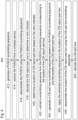
- FIGURE 4 is a flowchart illustrating an example method in a network node, according to certain embodiments. In particular embodiments, one or more steps of FIGURE 4 may be performed by network node 160 described with respect to FIGURE 3 .
- the network node is operable to decode a CSI report in a PUSCH.
- the method begins at step 412, where the network node (e.g., network node 160) generates a PUSCH scrambling sequence for descrambling a PUSCH without accounting for the existence of a CSI report part two.
- network node 160 may generate a PUSCH scrambling sequence as described with respect to step 0 of FIGURE 2 .
- the PUSCH may account for one or two bits HARQ indications and CSI part one, but not a 1 or 2 bit CSI part two.
- the network node receives the PUSCH from a wireless device.
- the PUSCH comprises a CSI report part one and a CSI report part two.
- network node 160 may receive a PUSCH from wireless device 110.
- the PUSCH may additionally include HARQ indications and data.
- the network node descrambles the PUSCH using the PUSCH scrambling sequence from step 414.
- network node 160 may descramble the PUSCH as described with respect to step 1 of FIGURE 2 .
- the network node decodes the CSI report part one from the descrambled PUSCH to determine a rank indicator.
- the network node determines a location of CSI report part two soft bits in the PUSCH based on the rank indicator. Examples are described with respect to steps 2 and 3 of FIGURE 2 .
- the network node extracts a scrambling sequence from the PUSCH scrambling sequence corresponding to the location of the CSI report part two in the PUSCH.
- network node 160 may extract the scrambling sequence as described with respect to step 4 of FIGURE 2 .
- the network node generates a CSI part two scrambling sequence based on the PUSCH scrambling sequence and the location of the CSI report part two in the PUSCH with correct x and y locations.
- network node 160 may generate the CSI part two scrambling sequence as described with respect to step 6 of FIGURE 2 .
- the network node applies the extracted scrambling sequence to the location of the CSI report part two soft bits in the PUSCH to undo the incorrect scrambling.
- network node 160 may apply the extracted scrambling sequence as described with respect to step 5 of FIGURE 2 .
- the network node descrambles the location of the CSI report part two soft bits in the PUSCH using the CSI part two scrambling sequence.
- the CSI part two scrambling sequence is now the correct scrambling sequence that accounts for CSI report part two and the network node is able to descramble the CSI part two correctly.
- network node 160 may descramble the CSI report part two as described with respect to step 7 of FIGURE 2 .
- the network node decodes the CSI part two.
- the network node may decode the CSI part two as described with respect to steps 8 and 9 of FIGURE 2 .
- FIGURE 5 illustrates a schematic block diagram of an apparatus in a wireless network (for example, the wireless network illustrated in FIGURE 3 ).
- the apparatus may comprise a network node (e.g., network node 160 in FIGURE 3 ).
- Apparatus 1600 is operable to carry out the example method described with reference to FIGURE 4 .
- Apparatus 1600 may be operable to carry out other processes or methods disclosed herein. It is also to be understood that the method of FIGURE 4 is not necessarily carried out solely by apparatus 1600. At least some operations of the method can be performed by one or more other entities.
- Virtual apparatus 1600 may comprise processing circuitry, which may include one or more microprocessor or microcontrollers, as well as other digital hardware, which may include digital signal processors (DSPs), special-purpose digital logic, and the like.
- the processing circuitry may be configured to execute program code stored in memory, which may include one or several types of memory such as read-only memory (ROM), random-access memory, cache memory, flash memory devices, optical storage devices, etc.
- Program code stored in memory includes program instructions for executing one or more telecommunications and/or data communications protocols as well as instructions for carrying out one or more of the techniques described herein, in several embodiments.
- the processing circuitry may be used to cause receiving module 1602, decoding module 1604, and any other suitable units of apparatus 1600 to perform corresponding functions according one or more embodiments of the present disclosure.
- apparatus 1600 includes receiving module 1602 configured to receive a PUSCH according to any of the embodiments and examples described herein.
- Decoding module 1604 is configured to decode the PUSCH, according to any of the embodiments and examples described herein., such as described with respect to FIGURES 2 and 4 .
- the term unit may have conventional meaning in the field of electronics, electrical devices and/or electronic devices and may include, for example, electrical and/or electronic circuitry, devices, modules, processors, memories, logic solid state and/or discrete devices, computer programs or instructions for carrying out respective tasks, procedures, computations, outputs, and/or displaying functions, and so on, as such as those that are described herein.
- references in the specification to "one embodiment,” “an embodiment,” “an example embodiment,” etc., indicate that the embodiment described may include a particular feature, structure, or characteristic, but every embodiment may not necessarily include the particular feature, structure, or characteristic. Moreover, such phrases are not necessarily referring to the same embodiment. Further, when a particular feature, structure, or characteristic is described in connection with an embodiment, it is submitted that it is within the knowledge of one skilled in the art to implement such feature, structure, or characteristic in connection with other embodiments, whether or not explicitly described.
Landscapes
- Engineering & Computer Science (AREA)
- Computer Networks & Wireless Communication (AREA)
- Signal Processing (AREA)
- Quality & Reliability (AREA)
- Mobile Radio Communication Systems (AREA)
Claims (13)
- Verfahren, das von einem Netzwerkknoten durchgeführt wird, zur Decodierung eines Kanalzustandsinformationsberichts (CSI-Berichts), wobei das Verfahren umfasst:Erzeugen (412) einer Physical-Uplink-Shared-Channel-Verwürfelungssequenz (PUSCH-Verwürfelungssequenz) zum Entwürfeln eines PUSCH, ohne das Vorhandensein eines CSI-Berichts Teil zwei zu berücksichtigen;Empfangen (414) des PUSCH von einer drahtlosen Vorrichtung, wobei der PUSCH einen CSI-Bericht Teil eins und einen CSI-Bericht Teil zwei umfasst, wobei der CSI-Bericht Teil eins und der CSI-Bericht Teil unabhängig voneinander codiert sind;Entwürfeln (416) des PUSCH unter Verwendung der PUSCH-Verwürfelungssequenz;Decodieren (418) des CSI-Berichts Teil eins aus dem entwürfelten PUSCH, um einen Rang-Indikator zu bestimmen;Bestimmen (420) einer Position von Softbits des CSI-Berichts Teil zwei im PUSCH basierend auf dem Rang-Indikator;Extrahieren (422) einer Verwürfelungssequenz aus der PUSCH-Verwürfelungssequenz, die der Position des CSI-Berichts Teil zwei im PUSCH entspricht;Erzeugen (424) einer Verwürfelungssequenz des CSI Teil zwei basierend auf der PUSCH-Verwürfelungssequenz und der Position des CSI-Berichts Teil zwei im PUSCH mit korrekter x- und y-Position;Anwenden (426) der extrahierten Verwürfelungssequenz auf die Position der Softbits des CSI-Berichts Teil zwei im PUSCH, um die inkorrekte Verwürfelung rückgängig zu machen;Entwürfeln (428) der Position der Softbits des CSI-Berichts Teil zwei im PUSCH unter Verwendung der Verwürfelungssequenz des CSI Teil zwei; undDecodieren (430) des CSI Teil zwei.
- Verfahren nach Anspruch 1, wobei das Decodieren des CSI Teil zwei ohne Verzögerung der Decodierung von CSI Teil eins oder Rückmeldung hinsichtlich hybrider automatischer Wiederholungsanforderung (HARQ) durchgeführt wird.
- Verfahren nach einem der Ansprüche 1 bis 2, wobei es sich bei dem CSI-Bericht Teil zwei um ein Bit handelt.
- Verfahren nach einem der Ansprüche 1 bis 2, wobei es sich bei dem CSI-Bericht Teil zwei um zwei Bits handelt.
- Verfahren nach einem der Ansprüche 1 bis 4, wobei der PUSCH ferner 1 oder 2 Bits Rückmeldung hinsichtlich hybrider automatischer Wiederholungsanforderung (HARQ) umfasst und die PUSCH-Verwürfelungssequenz die 1 oder 2 Bits HARQ-Rückmeldung berücksichtigt.
- Verfahren nach einem der Ansprüche 1 bis 5, wobei der PUSCH ferner Daten umfasst.
- Netzwerkknoten (160) zum Decodieren eines Kanalzustandsinformationsberichts (CSI-Berichts), wobei der Netzwerkknoten Verarbeitungsschaltungsanordnung (170) umfasst, die konfiguriert ist zum:Erzeugen einer Physical-Uplink-Shared-Channel-Verwürfelungssequenz (PUSCH-Verwürfelungssequenz) zum Entwürfeln eines PUSCH, ohne das Vorhandensein eines CSI-Berichts Teil zwei zu berücksichtigen;Empfangen des PUSCH von einer drahtlosen Vorrichtung, wobei der PUSCH einen CSI-Bericht Teil eins und einen CSI-Bericht Teil zwei umfasst, wobei der CSI-Bericht Teil eins und der CSI-Bericht Teil unabhängig voneinander codiert sind;Entwürfeln des PUSCH unter Verwendung der PUSCH-Verwürfelungssequenz;Decodieren des CSI-Berichts Teil eins aus dem entwürfelten PUSCH, um einen Rang-Indikator zu bestimmen;Bestimmen einer Position von Softbits des CSI-Berichts Teil zwei im PUSCH basierend auf dem Rang-Indikator;Extrahieren einer Verwürfelungssequenz aus der PUSCH-Verwürfelungssequenz, die der Position des CSI-Berichts Teil zwei im PUSCH entspricht;Erzeugen einer Verwürfelungssequenz des CSI Teil zwei basierend auf der PUSCH-Verwürfelungssequenz und der Position des CSI-Berichts Teil zwei im PUSCH mit korrekter x- und y-Position;Anwenden der extrahierten Verwürfelungssequenz auf die Position der Softbits des CSI-Berichts Teil zwei im PUSCH, um die inkorrekte Verwürfelung rückgängig zu machen;Entwürfeln der Position der Softbits des CSI-Berichts Teil zwei im PUSCH unter Verwendung der Verwürfelungssequenz des CSI Teil zwei; undDecodieren des CSI Teil zwei.
- Netzwerkknoten nach Anspruch 7, wobei das Decodieren des CSI Teil zwei ohne Verzögerung der Decodierung von CSI Teil eins oder Rückmeldung hinsichtlich hybrider automatischer Wiederholungsanforderung (HARQ) durchgeführt wird.
- Netzwerkknoten nach einem der Ansprüche 7 bis 8, wobei es sich bei dem CSI-Bericht Teil zwei um ein Bit handelt.
- Netzwerkknoten nach einem der Ansprüche 7 bis 8, wobei es sich bei dem CSI-Bericht Teil zwei um zwei Bits handelt.
- Netzwerkknoten nach einem der Ansprüche 7 bis 10, wobei der PUSCH ferner 1 oder 2 Bits Rückmeldung hinsichtlich hybrider automatischer Wiederholungsanforderung (HARQ) umfasst und die PUSCH-Verwürfelungssequenz die 1 oder 2 Bits HARQ-Rückmeldung berücksichtigt.
- Netzwerkknoten nach einem der Ansprüche 7 bis 11, wobei der PUSCH ferner Daten umfasst.
- Computerprogrammprodukt, umfassend ein nichttransitorisches computerlesbares Medium, das computerlesbaren Programmcode speichert, wobei der computerlesbare Programmcode Anweisungen umfasst, die bei Ausführung durch Verarbeitungsschaltungsanordnung die Verarbeitungsschaltungsanordnung zum Durchführen eines der Verfahren nach Anspruch 1 bis 6 veranlassen.
Applications Claiming Priority (1)
| Application Number | Priority Date | Filing Date | Title |
|---|---|---|---|
| PCT/IB2020/059934 WO2022084723A1 (en) | 2020-10-22 | 2020-10-22 | Decoding channel state information report part two |
Publications (2)
| Publication Number | Publication Date |
|---|---|
| EP4233218A1 EP4233218A1 (de) | 2023-08-30 |
| EP4233218B1 true EP4233218B1 (de) | 2024-09-04 |
Family
ID=73040174
Family Applications (1)
| Application Number | Title | Priority Date | Filing Date |
|---|---|---|---|
| EP20800327.7A Active EP4233218B1 (de) | 2020-10-22 | 2020-10-22 | Decodierung von kanalstatusinformationsberichtsteil zwei |
Country Status (3)
| Country | Link |
|---|---|
| US (1) | US12426040B2 (de) |
| EP (1) | EP4233218B1 (de) |
| WO (1) | WO2022084723A1 (de) |
Families Citing this family (3)
| Publication number | Priority date | Publication date | Assignee | Title |
|---|---|---|---|---|
| EP4298745A1 (de) * | 2021-02-26 | 2024-01-03 | Telefonaktiebolaget LM Ericsson (publ) | Verfahren und vorrichtung zur erkennung unzuverlässiger uplink-steuerinformationen |
| CN117751673A (zh) * | 2021-07-30 | 2024-03-22 | 中兴通讯股份有限公司 | 用于参考信令设计和配置的系统和方法 |
| EP4315696A4 (de) * | 2021-10-13 | 2024-10-16 | Samsung Electronics Co., Ltd. | Verfahren und vorrichtung zur meldung des status einer automatischen wiederholungsanfrage in einem kommunikationssystem |
Family Cites Families (10)
| Publication number | Priority date | Publication date | Assignee | Title |
|---|---|---|---|---|
| US10492184B2 (en) * | 2016-12-09 | 2019-11-26 | Samsung Electronics Co., Ltd. | Multiplexing control information in a physical uplink data channel |
| US20190059013A1 (en) * | 2017-08-21 | 2019-02-21 | Samsung Electronics Co., Ltd. | Method and apparatus for multiplexing higher-resolution channel state information (csi) |
| WO2019138016A1 (en) * | 2018-01-12 | 2019-07-18 | Telefonaktiebolaget Lm Ericsson (Publ) | Channel state information reporting without uplink shared channel |
| US10680774B2 (en) * | 2018-01-12 | 2020-06-09 | Apple Inc. | Size determination for channel state information (CSI) part one and part two transmission of CSI report |
| US10952186B2 (en) * | 2018-01-12 | 2021-03-16 | Apple Inc. | Reserved resource elements for hybrid automatic repeat request bits |
| US10827516B2 (en) * | 2018-01-19 | 2020-11-03 | Qualcomm Incorporated | Resource splitting among different types of control information and uplink data for a transmission on an uplink shared channel |
| JP2020005127A (ja) * | 2018-06-28 | 2020-01-09 | シャープ株式会社 | 基地局装置、端末装置および通信方法 |
| KR102693787B1 (ko) | 2019-03-29 | 2024-08-13 | 텔레호낙티에볼라게트 엘엠 에릭슨(피유비엘) | 다중빔 프리코더 기반 채널 상태 정보 |
| WO2020250290A1 (ja) * | 2019-06-10 | 2020-12-17 | 株式会社Nttドコモ | 端末及び無線通信方法 |
| US11991113B2 (en) * | 2020-05-21 | 2024-05-21 | Qualcomm Incorporated | Positioning measurement reporting |
-
2020
- 2020-10-22 US US18/249,798 patent/US12426040B2/en active Active
- 2020-10-22 WO PCT/IB2020/059934 patent/WO2022084723A1/en not_active Ceased
- 2020-10-22 EP EP20800327.7A patent/EP4233218B1/de active Active
Also Published As
| Publication number | Publication date |
|---|---|
| WO2022084723A1 (en) | 2022-04-28 |
| US20230422241A1 (en) | 2023-12-28 |
| EP4233218A1 (de) | 2023-08-30 |
| US12426040B2 (en) | 2025-09-23 |
Similar Documents
| Publication | Publication Date | Title |
|---|---|---|
| US11121814B2 (en) | Techniques of CSI feedback with unequal error protection messages | |
| EP3895330B1 (de) | Meldung von koeffizienten für kanalzustandsinformationen | |
| EP3522384B1 (de) | Verfahren und vorrichtung zur festlegung einer vorcodierungsmatrix | |
| EP4436291A1 (de) | Kommunikationsverfahren und kommunikationsvorrichtung | |
| US11936442B2 (en) | Multibeam precoder based channel state information | |
| EP3678403A1 (de) | Kommunikationsverfahren und -vorrichtung | |
| EP4044444A1 (de) | Verfahren zum melden von kanalzustandsinformationen und kommunikationsgerät | |
| EP2498417A2 (de) | Verfahren zur übertragung von kanalqualitätsinformationen und vorrichtung dafür | |
| EP2981014A1 (de) | Vorcodierungsmatrixanzeigefeedbackverfahren, empfangsende und übertragungsende | |
| EP4099783B1 (de) | Messanzeigeverfahren für kanalzustandsinformationen (csi) und kommunikationsvorrichtung | |
| EP4233218B1 (de) | Decodierung von kanalstatusinformationsberichtsteil zwei | |
| EP2893753A1 (de) | Kommunikationssystem zum konfigurieren von kanalstatusinformationen | |
| CN108809578A (zh) | 传输数据的方法、终端设备和网络设备 | |
| EP3758246A1 (de) | Verfahren und vorrichtung zur auswahl einer uplink-antenne | |
| EP3605909B1 (de) | Verfahren zum senden von informationen und vorrichtung dafür und verfahren zum empfangen von informationen und vorrichtung dafür | |
| CN103650368A (zh) | 信道状态信息发射方法和用户设备以及信道状态信息接收方法和基站 | |
| CN103391577A (zh) | 无线通信系统中的用于下行链路协调多点的信令 | |
| CN103748938A (zh) | 用信号传送用于上行链路协作多点(CoMP)的功率分配参数 | |
| CN109565829A (zh) | 聚合dci消息技术 | |
| JP2017509280A (ja) | チャネル状態情報を量子化する方法および装置 | |
| CN112703761B (zh) | 用于测量无线通信系统中的终端之间的链路的方法和设备 | |
| CN102075294A (zh) | 一种协作预编码方法、协作信息交互方法及系统 | |
| EP4131825B1 (de) | Uplink-referenzsignalsendeverfahren, kommunikationsvorrichtung und computerlesbares speichermedium | |
| EP2403157A1 (de) | Informationsübertragungsverfahren und einrichtung | |
| CN103516501A (zh) | 一种发送和接收反馈信息的方法、系统及装置 |
Legal Events
| Date | Code | Title | Description |
|---|---|---|---|
| STAA | Information on the status of an ep patent application or granted ep patent |
Free format text: STATUS: UNKNOWN |
|
| STAA | Information on the status of an ep patent application or granted ep patent |
Free format text: STATUS: THE INTERNATIONAL PUBLICATION HAS BEEN MADE |
|
| PUAI | Public reference made under article 153(3) epc to a published international application that has entered the european phase |
Free format text: ORIGINAL CODE: 0009012 |
|
| STAA | Information on the status of an ep patent application or granted ep patent |
Free format text: STATUS: REQUEST FOR EXAMINATION WAS MADE |
|
| 17P | Request for examination filed |
Effective date: 20230504 |
|
| AK | Designated contracting states |
Kind code of ref document: A1 Designated state(s): AL AT BE BG CH CY CZ DE DK EE ES FI FR GB GR HR HU IE IS IT LI LT LU LV MC MK MT NL NO PL PT RO RS SE SI SK SM TR |
|
| DAV | Request for validation of the european patent (deleted) | ||
| DAX | Request for extension of the european patent (deleted) | ||
| GRAP | Despatch of communication of intention to grant a patent |
Free format text: ORIGINAL CODE: EPIDOSNIGR1 |
|
| STAA | Information on the status of an ep patent application or granted ep patent |
Free format text: STATUS: GRANT OF PATENT IS INTENDED |
|
| INTG | Intention to grant announced |
Effective date: 20240315 |
|
| GRAS | Grant fee paid |
Free format text: ORIGINAL CODE: EPIDOSNIGR3 |
|
| GRAA | (expected) grant |
Free format text: ORIGINAL CODE: 0009210 |
|
| STAA | Information on the status of an ep patent application or granted ep patent |
Free format text: STATUS: THE PATENT HAS BEEN GRANTED |
|
| AK | Designated contracting states |
Kind code of ref document: B1 Designated state(s): AL AT BE BG CH CY CZ DE DK EE ES FI FR GB GR HR HU IE IS IT LI LT LU LV MC MK MT NL NO PL PT RO RS SE SI SK SM TR |
|
| REG | Reference to a national code |
Ref country code: GB Ref legal event code: FG4D |
|
| REG | Reference to a national code |
Ref country code: CH Ref legal event code: EP |
|
| REG | Reference to a national code |
Ref country code: IE Ref legal event code: FG4D |
|
| REG | Reference to a national code |
Ref country code: DE Ref legal event code: R096 Ref document number: 602020037189 Country of ref document: DE |
|
| REG | Reference to a national code |
Ref country code: NL Ref legal event code: FP |
|
| REG | Reference to a national code |
Ref country code: LT Ref legal event code: MG9D |
|
| PGFP | Annual fee paid to national office [announced via postgrant information from national office to epo] |
Ref country code: DE Payment date: 20241029 Year of fee payment: 5 |
|
| PG25 | Lapsed in a contracting state [announced via postgrant information from national office to epo] |
Ref country code: NO Free format text: LAPSE BECAUSE OF FAILURE TO SUBMIT A TRANSLATION OF THE DESCRIPTION OR TO PAY THE FEE WITHIN THE PRESCRIBED TIME-LIMIT Effective date: 20241204 |
|
| PG25 | Lapsed in a contracting state [announced via postgrant information from national office to epo] |
Ref country code: GR Free format text: LAPSE BECAUSE OF FAILURE TO SUBMIT A TRANSLATION OF THE DESCRIPTION OR TO PAY THE FEE WITHIN THE PRESCRIBED TIME-LIMIT Effective date: 20241205 Ref country code: FI Free format text: LAPSE BECAUSE OF FAILURE TO SUBMIT A TRANSLATION OF THE DESCRIPTION OR TO PAY THE FEE WITHIN THE PRESCRIBED TIME-LIMIT Effective date: 20240904 Ref country code: PL Free format text: LAPSE BECAUSE OF FAILURE TO SUBMIT A TRANSLATION OF THE DESCRIPTION OR TO PAY THE FEE WITHIN THE PRESCRIBED TIME-LIMIT Effective date: 20240904 |
|
| PGFP | Annual fee paid to national office [announced via postgrant information from national office to epo] |
Ref country code: GB Payment date: 20241028 Year of fee payment: 5 |
|
| PG25 | Lapsed in a contracting state [announced via postgrant information from national office to epo] |
Ref country code: BG Free format text: LAPSE BECAUSE OF FAILURE TO SUBMIT A TRANSLATION OF THE DESCRIPTION OR TO PAY THE FEE WITHIN THE PRESCRIBED TIME-LIMIT Effective date: 20240904 |
|
| PG25 | Lapsed in a contracting state [announced via postgrant information from national office to epo] |
Ref country code: LV Free format text: LAPSE BECAUSE OF FAILURE TO SUBMIT A TRANSLATION OF THE DESCRIPTION OR TO PAY THE FEE WITHIN THE PRESCRIBED TIME-LIMIT Effective date: 20240904 |
|
| PG25 | Lapsed in a contracting state [announced via postgrant information from national office to epo] |
Ref country code: HR Free format text: LAPSE BECAUSE OF FAILURE TO SUBMIT A TRANSLATION OF THE DESCRIPTION OR TO PAY THE FEE WITHIN THE PRESCRIBED TIME-LIMIT Effective date: 20240904 |
|
| PG25 | Lapsed in a contracting state [announced via postgrant information from national office to epo] |
Ref country code: RS Free format text: LAPSE BECAUSE OF FAILURE TO SUBMIT A TRANSLATION OF THE DESCRIPTION OR TO PAY THE FEE WITHIN THE PRESCRIBED TIME-LIMIT Effective date: 20241204 Ref country code: ES Free format text: LAPSE BECAUSE OF FAILURE TO SUBMIT A TRANSLATION OF THE DESCRIPTION OR TO PAY THE FEE WITHIN THE PRESCRIBED TIME-LIMIT Effective date: 20240904 |
|
| PG25 | Lapsed in a contracting state [announced via postgrant information from national office to epo] |
Ref country code: RS Free format text: LAPSE BECAUSE OF FAILURE TO SUBMIT A TRANSLATION OF THE DESCRIPTION OR TO PAY THE FEE WITHIN THE PRESCRIBED TIME-LIMIT Effective date: 20241204 Ref country code: PL Free format text: LAPSE BECAUSE OF FAILURE TO SUBMIT A TRANSLATION OF THE DESCRIPTION OR TO PAY THE FEE WITHIN THE PRESCRIBED TIME-LIMIT Effective date: 20240904 Ref country code: NO Free format text: LAPSE BECAUSE OF FAILURE TO SUBMIT A TRANSLATION OF THE DESCRIPTION OR TO PAY THE FEE WITHIN THE PRESCRIBED TIME-LIMIT Effective date: 20241204 Ref country code: LV Free format text: LAPSE BECAUSE OF FAILURE TO SUBMIT A TRANSLATION OF THE DESCRIPTION OR TO PAY THE FEE WITHIN THE PRESCRIBED TIME-LIMIT Effective date: 20240904 Ref country code: HR Free format text: LAPSE BECAUSE OF FAILURE TO SUBMIT A TRANSLATION OF THE DESCRIPTION OR TO PAY THE FEE WITHIN THE PRESCRIBED TIME-LIMIT Effective date: 20240904 Ref country code: GR Free format text: LAPSE BECAUSE OF FAILURE TO SUBMIT A TRANSLATION OF THE DESCRIPTION OR TO PAY THE FEE WITHIN THE PRESCRIBED TIME-LIMIT Effective date: 20241205 Ref country code: FI Free format text: LAPSE BECAUSE OF FAILURE TO SUBMIT A TRANSLATION OF THE DESCRIPTION OR TO PAY THE FEE WITHIN THE PRESCRIBED TIME-LIMIT Effective date: 20240904 Ref country code: ES Free format text: LAPSE BECAUSE OF FAILURE TO SUBMIT A TRANSLATION OF THE DESCRIPTION OR TO PAY THE FEE WITHIN THE PRESCRIBED TIME-LIMIT Effective date: 20240904 Ref country code: BG Free format text: LAPSE BECAUSE OF FAILURE TO SUBMIT A TRANSLATION OF THE DESCRIPTION OR TO PAY THE FEE WITHIN THE PRESCRIBED TIME-LIMIT Effective date: 20240904 |
|
| REG | Reference to a national code |
Ref country code: AT Ref legal event code: MK05 Ref document number: 1721494 Country of ref document: AT Kind code of ref document: T Effective date: 20240904 |
|
| PG25 | Lapsed in a contracting state [announced via postgrant information from national office to epo] |
Ref country code: PT Free format text: LAPSE BECAUSE OF FAILURE TO SUBMIT A TRANSLATION OF THE DESCRIPTION OR TO PAY THE FEE WITHIN THE PRESCRIBED TIME-LIMIT Effective date: 20250106 Ref country code: IS Free format text: LAPSE BECAUSE OF FAILURE TO SUBMIT A TRANSLATION OF THE DESCRIPTION OR TO PAY THE FEE WITHIN THE PRESCRIBED TIME-LIMIT Effective date: 20250104 |
|
| PG25 | Lapsed in a contracting state [announced via postgrant information from national office to epo] |
Ref country code: RO Free format text: LAPSE BECAUSE OF FAILURE TO SUBMIT A TRANSLATION OF THE DESCRIPTION OR TO PAY THE FEE WITHIN THE PRESCRIBED TIME-LIMIT Effective date: 20240904 Ref country code: SM Free format text: LAPSE BECAUSE OF FAILURE TO SUBMIT A TRANSLATION OF THE DESCRIPTION OR TO PAY THE FEE WITHIN THE PRESCRIBED TIME-LIMIT Effective date: 20240904 |
|
| PG25 | Lapsed in a contracting state [announced via postgrant information from national office to epo] |
Ref country code: AT Free format text: LAPSE BECAUSE OF FAILURE TO SUBMIT A TRANSLATION OF THE DESCRIPTION OR TO PAY THE FEE WITHIN THE PRESCRIBED TIME-LIMIT Effective date: 20240904 Ref country code: EE Free format text: LAPSE BECAUSE OF FAILURE TO SUBMIT A TRANSLATION OF THE DESCRIPTION OR TO PAY THE FEE WITHIN THE PRESCRIBED TIME-LIMIT Effective date: 20240904 |
|
| PG25 | Lapsed in a contracting state [announced via postgrant information from national office to epo] |
Ref country code: CZ Free format text: LAPSE BECAUSE OF FAILURE TO SUBMIT A TRANSLATION OF THE DESCRIPTION OR TO PAY THE FEE WITHIN THE PRESCRIBED TIME-LIMIT Effective date: 20240904 |
|
| PG25 | Lapsed in a contracting state [announced via postgrant information from national office to epo] |
Ref country code: IT Free format text: LAPSE BECAUSE OF FAILURE TO SUBMIT A TRANSLATION OF THE DESCRIPTION OR TO PAY THE FEE WITHIN THE PRESCRIBED TIME-LIMIT Effective date: 20240904 Ref country code: SK Free format text: LAPSE BECAUSE OF FAILURE TO SUBMIT A TRANSLATION OF THE DESCRIPTION OR TO PAY THE FEE WITHIN THE PRESCRIBED TIME-LIMIT Effective date: 20240904 |
|
| REG | Reference to a national code |
Ref country code: CH Ref legal event code: PL |
|
| REG | Reference to a national code |
Ref country code: DE Ref legal event code: R097 Ref document number: 602020037189 Country of ref document: DE |
|
| PG25 | Lapsed in a contracting state [announced via postgrant information from national office to epo] |
Ref country code: MC Free format text: LAPSE BECAUSE OF FAILURE TO SUBMIT A TRANSLATION OF THE DESCRIPTION OR TO PAY THE FEE WITHIN THE PRESCRIBED TIME-LIMIT Effective date: 20240904 |
|
| PG25 | Lapsed in a contracting state [announced via postgrant information from national office to epo] |
Ref country code: DK Free format text: LAPSE BECAUSE OF FAILURE TO SUBMIT A TRANSLATION OF THE DESCRIPTION OR TO PAY THE FEE WITHIN THE PRESCRIBED TIME-LIMIT Effective date: 20240904 |
|
| PLBE | No opposition filed within time limit |
Free format text: ORIGINAL CODE: 0009261 |
|
| STAA | Information on the status of an ep patent application or granted ep patent |
Free format text: STATUS: NO OPPOSITION FILED WITHIN TIME LIMIT |
|
| PG25 | Lapsed in a contracting state [announced via postgrant information from national office to epo] |
Ref country code: LU Free format text: LAPSE BECAUSE OF NON-PAYMENT OF DUE FEES Effective date: 20241022 Ref country code: BE Free format text: LAPSE BECAUSE OF NON-PAYMENT OF DUE FEES Effective date: 20241031 |
|
| PG25 | Lapsed in a contracting state [announced via postgrant information from national office to epo] |
Ref country code: CH Free format text: LAPSE BECAUSE OF NON-PAYMENT OF DUE FEES Effective date: 20241031 |
|
| REG | Reference to a national code |
Ref country code: BE Ref legal event code: MM Effective date: 20241031 |
|
| 26N | No opposition filed |
Effective date: 20250605 |
|
| PG25 | Lapsed in a contracting state [announced via postgrant information from national office to epo] |
Ref country code: SE Free format text: LAPSE BECAUSE OF FAILURE TO SUBMIT A TRANSLATION OF THE DESCRIPTION OR TO PAY THE FEE WITHIN THE PRESCRIBED TIME-LIMIT Effective date: 20240904 |
|
| PG25 | Lapsed in a contracting state [announced via postgrant information from national office to epo] |
Ref country code: FR Free format text: LAPSE BECAUSE OF NON-PAYMENT OF DUE FEES Effective date: 20241104 |
|
| PG25 | Lapsed in a contracting state [announced via postgrant information from national office to epo] |
Ref country code: IE Free format text: LAPSE BECAUSE OF NON-PAYMENT OF DUE FEES Effective date: 20241022 |
|
| PGFP | Annual fee paid to national office [announced via postgrant information from national office to epo] |
Ref country code: NL Payment date: 20251026 Year of fee payment: 6 |