EP4233181B1 - Strahlmeldungsverbesserung für simultanen iab-empfang - Google Patents
Strahlmeldungsverbesserung für simultanen iab-empfang Download PDFInfo
- Publication number
- EP4233181B1 EP4233181B1 EP21790193.3A EP21790193A EP4233181B1 EP 4233181 B1 EP4233181 B1 EP 4233181B1 EP 21790193 A EP21790193 A EP 21790193A EP 4233181 B1 EP4233181 B1 EP 4233181B1
- Authority
- EP
- European Patent Office
- Prior art keywords
- node
- iab
- parent
- beams
- indication
- Prior art date
- Legal status (The legal status is an assumption and is not a legal conclusion. Google has not performed a legal analysis and makes no representation as to the accuracy of the status listed.)
- Active
Links
Images


Classifications
-
- H—ELECTRICITY
- H04—ELECTRIC COMMUNICATION TECHNIQUE
- H04B—TRANSMISSION
- H04B7/00—Radio transmission systems, i.e. using radiation field
- H04B7/02—Diversity systems; Multi-antenna system, i.e. transmission or reception using multiple antennas
- H04B7/04—Diversity systems; Multi-antenna system, i.e. transmission or reception using multiple antennas using two or more spaced independent antennas
- H04B7/08—Diversity systems; Multi-antenna system, i.e. transmission or reception using multiple antennas using two or more spaced independent antennas at the receiving station
- H04B7/0868—Hybrid systems, i.e. switching and combining
- H04B7/088—Hybrid systems, i.e. switching and combining using beam selection
-
- H—ELECTRICITY
- H04—ELECTRIC COMMUNICATION TECHNIQUE
- H04L—TRANSMISSION OF DIGITAL INFORMATION, e.g. TELEGRAPHIC COMMUNICATION
- H04L5/00—Arrangements affording multiple use of the transmission path
- H04L5/003—Arrangements for allocating sub-channels of the transmission path
- H04L5/0032—Distributed allocation, i.e. involving a plurality of allocating devices, each making partial allocation
- H04L5/0035—Resource allocation in a cooperative multipoint environment
-
- H—ELECTRICITY
- H04—ELECTRIC COMMUNICATION TECHNIQUE
- H04B—TRANSMISSION
- H04B7/00—Radio transmission systems, i.e. using radiation field
- H04B7/02—Diversity systems; Multi-antenna system, i.e. transmission or reception using multiple antennas
- H04B7/022—Site diversity; Macro-diversity
- H04B7/024—Co-operative use of antennas of several sites, e.g. in co-ordinated multipoint or co-operative multiple-input multiple-output [MIMO] systems
-
- H—ELECTRICITY
- H04—ELECTRIC COMMUNICATION TECHNIQUE
- H04B—TRANSMISSION
- H04B7/00—Radio transmission systems, i.e. using radiation field
- H04B7/02—Diversity systems; Multi-antenna system, i.e. transmission or reception using multiple antennas
- H04B7/04—Diversity systems; Multi-antenna system, i.e. transmission or reception using multiple antennas using two or more spaced independent antennas
- H04B7/0408—Diversity systems; Multi-antenna system, i.e. transmission or reception using multiple antennas using two or more spaced independent antennas using two or more beams, i.e. beam diversity
-
- H—ELECTRICITY
- H04—ELECTRIC COMMUNICATION TECHNIQUE
- H04B—TRANSMISSION
- H04B7/00—Radio transmission systems, i.e. using radiation field
- H04B7/02—Diversity systems; Multi-antenna system, i.e. transmission or reception using multiple antennas
- H04B7/04—Diversity systems; Multi-antenna system, i.e. transmission or reception using multiple antennas using two or more spaced independent antennas
- H04B7/06—Diversity systems; Multi-antenna system, i.e. transmission or reception using multiple antennas using two or more spaced independent antennas at the transmitting station
- H04B7/0613—Diversity systems; Multi-antenna system, i.e. transmission or reception using multiple antennas using two or more spaced independent antennas at the transmitting station using simultaneous transmission
- H04B7/0615—Diversity systems; Multi-antenna system, i.e. transmission or reception using multiple antennas using two or more spaced independent antennas at the transmitting station using simultaneous transmission of weighted versions of same signal
- H04B7/0619—Diversity systems; Multi-antenna system, i.e. transmission or reception using multiple antennas using two or more spaced independent antennas at the transmitting station using simultaneous transmission of weighted versions of same signal using feedback from receiving side
- H04B7/0621—Feedback content
-
- H—ELECTRICITY
- H04—ELECTRIC COMMUNICATION TECHNIQUE
- H04B—TRANSMISSION
- H04B7/00—Radio transmission systems, i.e. using radiation field
- H04B7/02—Diversity systems; Multi-antenna system, i.e. transmission or reception using multiple antennas
- H04B7/04—Diversity systems; Multi-antenna system, i.e. transmission or reception using multiple antennas using two or more spaced independent antennas
- H04B7/06—Diversity systems; Multi-antenna system, i.e. transmission or reception using multiple antennas using two or more spaced independent antennas at the transmitting station
- H04B7/0686—Hybrid systems, i.e. switching and simultaneous transmission
- H04B7/0695—Hybrid systems, i.e. switching and simultaneous transmission using beam selection
- H04B7/06952—Selecting one or more beams from a plurality of beams, e.g. beam training, management or sweeping
- H04B7/0696—Determining beam pairs
-
- H—ELECTRICITY
- H04—ELECTRIC COMMUNICATION TECHNIQUE
- H04B—TRANSMISSION
- H04B7/00—Radio transmission systems, i.e. using radiation field
- H04B7/14—Relay systems
- H04B7/15—Active relay systems
- H04B7/155—Ground-based stations
- H04B7/15528—Control of operation parameters of a relay station to exploit the physical medium
-
- H—ELECTRICITY
- H04—ELECTRIC COMMUNICATION TECHNIQUE
- H04W—WIRELESS COMMUNICATION NETWORKS
- H04W72/00—Local resource management
- H04W72/12—Wireless traffic scheduling
- H04W72/1263—Mapping of traffic onto schedule, e.g. scheduled allocation or multiplexing of flows
- H04W72/1268—Mapping of traffic onto schedule, e.g. scheduled allocation or multiplexing of flows of uplink data flows
-
- H—ELECTRICITY
- H04—ELECTRIC COMMUNICATION TECHNIQUE
- H04W—WIRELESS COMMUNICATION NETWORKS
- H04W88/00—Devices specially adapted for wireless communication networks, e.g. terminals, base stations or access point devices
- H04W88/08—Access point devices
- H04W88/085—Access point devices with remote components
Definitions
- the example and non-limiting embodiments relate generally to communications and, more particularly, to facilitating use of backhaul links in a NR/5G network.
- a gNB in NR/5G comprising a centralized unit and a distributed unit, to use a backhaul between gNBs/portions of a gNB to relay information between a user equipment and a network.
- LG ELECTRONICS "Discussion on CSI framework for NR", vol. RAN WG1, no. Athens, Greece; 20170213 - 20170217, (20170212), 3GPP DRAFT; R1-1702455 NR_CSI_FRAMEWORK_FINAL, 3RD GENERATION PARTNERSHIP PROJECT (3GPP), MOBILE COMPETENCE CENTRE ; 650, ROUTE DES LUCIOLES ; F-06921 SOPHIA-ANTIPOLIS CEDEX ; FRANCE, URL: http://www.3gpp.org/ftp/Meetings_3GPP_SYNC/RAN1/Docs/, (20170212), XP051209609 discusses resource/measurement/reporting settings for CSI acquisition framework in NR.
- ZTE ET AL "SDM scheme and antenna configuration for IAB node", vol. RAN WG1, no. e-Meeting; 20200817 - 20200828, (20200807), 3GPP DRAFT; R1-2006622, 3RD GENERATION PARTNERSHIP PROJECT (3GPP), MOBILE COMPETENCE CENTRE ; 650, ROUTE DES LUCIOLES ; F-06921 SOPHIA-ANTIPOLIS CEDEX ; FRANCE, URL: https:/ftp.3gpp.org/tsg_ran/WG1_RL1/TSGR1_102-e/Docs/R1-2006622.zip R1-2006622 SDM and antenna configuration for IAB node.docx, (20200807), XP051915419
- FIG. 1 this figure shows a block diagram of one possible and non-limiting example in which the examples may be practiced.
- a user equipment (UE) 110 radio access network (RAN) node 170, and network element(s) 190 are illustrated.
- the user equipment (UE) 110 is in wireless communication with a wireless network 100.
- a UE is a wireless device that can access the wireless network 100.
- the UE 110 includes one or more processors 120, one or more memories 125, and one or more transceivers 130 interconnected through one or more buses 127.
- Each of the one or more transceivers 130 includes a receiver, Rx, 132 and a transmitter, Tx, 133.
- the one or more buses 127 may be address, data, or control buses, and may include any interconnection mechanism, such as a series of lines on a motherboard or integrated circuit, fiber optics or other optical communication equipment, and the like.
- the one or more transceivers 130 are connected to one or more antennas 128.
- the one or more memories 125 include computer program code 123.
- the UE 110 includes a module 140, comprising one of or both parts 140-1 and/or 140-2, which may be implemented in a number of ways.
- the module 140 may be implemented in hardware as module 140-1, such as being implemented as part of the one or more processors 120.
- the module 140-1 may be implemented also as an integrated circuit or through other hardware such as a programmable gate array.
- the module 140 may be implemented as module 140-2, which is implemented as computer program code 123 and is executed by the one or more processors 120.
- the one or more memories 125 and the computer program code 123 may be configured to, with the one or more processors 120, cause the user equipment 110 to perform one or more of the operations as described herein.
- the UE 110 communicates with RAN node 170 via a wireless link 111.
- the RAN node 170 in this example is a base station that provides access by wireless devices such as the UE 110 to the wireless network 100.
- the RAN node 170 may be, for example, a base station for 5G, also called New Radio (NR).
- the RAN node 170 may be a NG-RAN node, which is defined as either a gNB or a ng-eNB.
- a gNB is a node providing NR user plane and control plane protocol terminations towards the UE, and connected via the NG interface to a 5GC (such as, for example, the network element(s) 190).
- the ng-eNB is a node providing E-UTRA user plane and control plane protocol terminations towards the UE, and connected via the NG interface to the 5GC.
- the NG-RAN node may include multiple gNBs, which may also include a centralized unit (CU) (gNB-CU) 196 and distributed unit(s) (DUs) (gNB-DUs), of which DU 195 is shown.
- the DU may include or be coupled to and control a radio unit (RU).
- the gNB-CU is a logical node hosting RRC, SDAP and PDCP protocols of the gNB or RRC and PDCP protocols of the en-gNB that controls the operation of one or more gNB-DUs.
- the gNB-CU terminates the F1 interface connected with the gNB-DU.
- the F1 interface is illustrated as reference 198, although reference 198 also illustrates a link between remote elements of the RAN node 170 and centralized elements of the RAN node 170, such as between the gNB-CU 196 and the gNB-DU 195.
- the gNB-DU is a logical node hosting RLC, MAC and PHY layers of the gNB or en-gNB, and its operation is partly controlled by gNB-CU.
- One gNB-CU supports one or multiple cells.
- One cell is supported by only one gNB-DU.
- the gNB-DU terminates the F1 interface 198 connected with the gNB-CU.
- the DU 195 is considered to include the transceiver 160, e.g., as part of a RU, but some examples of this may have the transceiver 160 as part of a separate RU, e.g., under control of and connected to the DU 195.
- the RAN node 170 may also be an eNB (evolved NodeB) base station, for LTE (long term evolution), or any other suitable base station or node.
- eNB evolved NodeB
- the RAN node 170 includes one or more processors 152, one or more memories 155, one or more network interfaces (N/W I/F(s)) 161, and one or more transceivers 160 interconnected through one or more buses 157.
- Each of the one or more transceivers 160 includes a receiver, Rx, 162 and a transmitter, Tx, 163.
- the one or more transceivers 160 are connected to one or more antennas 158.
- the one or more memories 155 include computer program code 153.
- the CU 196 may include the processor(s) 152, memories 155, and network interfaces 161. Note that the DU 195 may also contain its own memory/memories and processor(s), and/or other hardware, but these are not shown.
- the RAN node 170 includes a module 150, comprising one of or both parts 150-1 and/or 150-2, which may be implemented in a number of ways.
- the module 150 may be implemented in hardware as module 150-1, such as being implemented as part of the one or more processors 152.
- the module 150-1 may be implemented also as an integrated circuit or through other hardware such as a programmable gate array.
- the module 150 may be implemented as module 150-2, which is implemented as computer program code 153 and is executed by the one or more processors 152.
- the one or more memories 155 and the computer program code 153 are configured to, with the one or more processors 152, cause the RAN node 170 to perform one or more of the operations as described herein.
- the functionality of the module 150 may be distributed, such as being distributed between the DU 195 and the CU 196, or be implemented solely in the DU 195.
- the one or more network interfaces 161 communicate over a network such as via the links 176 and 131.
- Two or more gNBs 170 may communicate using, e.g., link 176.
- the link 176 may be wired or wireless or both and may implement, for example, an Xn interface for 5G, an X2 interface for LTE, or other suitable interface for other standards.
- the one or more buses 157 may be address, data, or control buses, and may include any interconnection mechanism, such as a series of lines on a motherboard or integrated circuit, fiber optics or other optical communication equipment, wireless channels, and the like.
- the one or more transceivers 160 may be implemented as a remote radio head (RRH) 195 for LTE or a distributed unit (DU) 195 for gNB implementation for 5G, with the other elements of the RAN node 170 possibly being physically in a different location from the RRH/DU, and the one or more buses 157 could be implemented in part as, for example, fiber optic cable or other suitable network connection to connect the other elements (e.g., a centralized unit (CU), gNB-CU) of the RAN node 170 to the RRH/DU 195.
- Reference 198 also indicates those suitable network link(s).
- the cell makes up part of a base station. That is, there can be multiple cells per base station. For example, there could be three cells for a single carrier frequency and associated bandwidth, each cell covering one-third of a 360 degree area so that the single base station's coverage area covers an approximate oval or circle. Furthermore, each cell can correspond to a single carrier and a base station may use multiple carriers. So if there are three 120 degree cells per carrier and two carriers, then the base station has a total of 6 cells.
- the wireless network 100 may include a network element or elements 190 that may include core network functionality, and which provides connectivity via a link or links 181 with a further network, such as a telephone network and/or a data communications network (e.g., the Internet).
- a further network such as a telephone network and/or a data communications network (e.g., the Internet).
- core network functionality for 5G may include access and mobility management function(s) (AMF(s)) and/or user plane functions (UPF(s)) and/or session management function(s) (SMF(s)).
- AMF(s) access and mobility management function(s)
- UPF(s) user plane functions
- SMF(s) session management function
- Such core network functionality for LTE may include MME (Mobility Management Entity)/SGW (Serving Gateway) functionality. These are merely exemplary functions that may be supported by the network element(s) 190, and note that both 5G and LTE functions might be supported.
- the RAN node 170 is coupled via a link 131 to a network element 190.
- the link 131 may be implemented as, e.g., an NG interface for 5G, or an S1 interface for LTE, or other suitable interface for other standards.
- the network element 190 includes one or more processors 175, one or more memories 171, and one or more network interfaces (N/W I/F(s)) 180, interconnected through one or more buses 185.
- the one or more memories 171 include computer program code 173.
- the one or more memories 171 and the computer program code 173 are configured to, with the one or more processors 175, cause the network element 190 to perform one or more operations.
- the wireless network 100 may implement network virtualization, which is the process of combining hardware and software network resources and network functionality into a single, software-based administrative entity, a virtual network.
- Network virtualization involves platform virtualization, often combined with resource virtualization.
- Network virtualization is categorized as either external, combining many networks, or parts of networks, into a virtual unit, or internal, providing network-like functionality to software containers on a single system. Note that the virtualized entities that result from the network virtualization are still implemented, at some level, using hardware such as processors 152 or 175 and memories 155 and 171, and also such virtualized entities create technical effects.
- the computer readable memories 125, 155, and 171 may be of any type suitable to the local technical environment and may be implemented using any suitable data storage technology, such as semiconductor based memory devices, flash memory, magnetic memory devices and systems, optical memory devices and systems, fixed memory and removable memory.
- the computer readable memories 125, 155, and 171 may be means for performing storage functions.
- the processors 120, 152, and 175 may be of any type suitable to the local technical environment, and may include one or more of general purpose computers, special purpose computers, microprocessors, digital signal processors (DSPs) and processors based on a multi-core processor architecture, as non-limiting examples.
- the processors 120, 152, and 175 may be means for performing functions, such as controlling the UE 110, RAN node 170, and other functions as described herein.
- the various examples of the user equipment 110 can include, but are not limited to, cellular telephones such as smart phones, tablets, personal digital assistants (PDAs) having wireless communication capabilities, portable computers having wireless communication capabilities, image capture devices such as digital cameras having wireless communication capabilities, gaming devices having wireless communication capabilities, music storage and playback appliances having wireless communication capabilities, Internet appliances permitting wireless Internet access and browsing, tablets with wireless communication capabilities, as well as portable units or terminals that incorporate combinations of such functions.
- cellular telephones such as smart phones, tablets, personal digital assistants (PDAs) having wireless communication capabilities, portable computers having wireless communication capabilities, image capture devices such as digital cameras having wireless communication capabilities, gaming devices having wireless communication capabilities, music storage and playback appliances having wireless communication capabilities, Internet appliances permitting wireless Internet access and browsing, tablets with wireless communication capabilities, as well as portable units or terminals that incorporate combinations of such functions.
- PDAs personal digital assistants
- portable computers having wireless communication capabilities
- image capture devices such as digital cameras having wireless communication capabilities
- gaming devices having wireless communication capabilities
- music storage and playback appliances having wireless communication capabilities
- FIG. 2 a schematic diagram illustrating an example of various devices in a network 100 is shown.
- the network 100 in this example supports a multi-hop self-backhaul whereby 5G may be used to transport packets between Integrated Access and Backhaul (IAB) nodes (12) and a Donor (20), such as with a fiber connection to the Next Generation Core (NG-Core or NGC) or Evolved Packet Core (EPC) for example.
- IAB nodes 12 IAB Node-1, 14; IAB Node-2, 16; and IAB Node-3, 18.
- NG-Core or NGC Next Generation Core
- EPC Evolved Packet Core
- Each IAB node consists, logically, of a Mobile Termination (MT) (e.g. IAB MT) that communicates with upstream nodes, and a RAN component, such as a Distributed Unit (DU) (e.g. IAB DU), that communicates with downstream IAB nodes or subscriber UEs 110.
- MT Mobile Termination
- DU Distributed Unit
- IAB DU Distributed Unit
- a gNB may comprise a split architecture in which a centralized unit (CU) and a distributed unit (DU) each perform a subset of the functionalities of the gNB.
- a mobile termination (MT) of an IAB node may communicate with a parent node, such as IAB donor, illustrated in FIG. 2 at 20.
- the IAB donor may comprise the centralized unit of the gNB and may also comprise the distributed unit.
- a distributed unit (DU) of an IAB node may communicate with a child node or a user equipment. For example, in the example of FIG.
- IAB donor 20 may transmit a packet over a backhaul to IAB Node-1, 14, which may forward the packet over a backhaul to IAB Node-3, 18, which may transmit the packet to a UE 110.
- This process may be considered a form of relaying.
- an IAB node is configured to perform simultaneous reception with both the MT and the DU, some packets may not be received due to frequency overlap between MT reception and DU reception, i.e. the same carrier frequencies may be used by both the MT and DU.
- Example embodiments of the present disclosure may relate to uplink reporting by the IAB MT that may facilitate simultaneous reception with MT and DU.
- Example embodiments of the present disclosure may relate to scenarios in which an IAB MT has a backhaul link with a single parent, or backhaul links with multiple parents.
- an integrated access backhaul mobile termination may be scheduled to perform reception with multiple beams, each from a different parent, i.e. IAB node or IAB donor.
- IAB MT reception (RX) beamforming may be implemented with hybrid beamforming, it may be that only one beam per panel (IAB MT panel) can be used for receiving at any time. But, if a single panel receives two beams from spatially separated parents, it may be understood that the transmission of only one of the two beams may be successfully received Without a clear understanding of the IAB-MT's capability of receiving two different beams (each from a different parent) with different panels, the transmission from one parent may fail.
- intra-frequency DC scenarios may rely on enhanced beam reporting, such that beam pairs that can be simultaneously received at the IAB MT may be reported towards the network/parents.
- RAN1 agreed on spatial division multiplexing/frequency division multiplexing (SDM/FDM) operation (Case #A and Case #B), and it is expected to consider these multiplexing modes with more details in the future, potentially with respect to: Case #6 and #7 timing modes; extensions for downlink/uplink (DL/UL) power control; cross-link interference (CLI); and/or interference measurements of backhaul (BH) links, as needed, to support simultaneous operation (transmission and/or reception).
- Case #A and #B are mentioned in the below agreement [Session notes for 8.10 (Enhancements to Integrated Access and Backhaul), 3GPP TSG RAN WG1 Meeting #102-e]:
- simultaneous reception at the integrated access and backhaul (IAB) node may require specification for the following cases: IAB mobile termination (MT) and IAB distributed unit (DU) supporting Case #B (i.e. simultaneous mobile termination reception and distributed unit reception), where IAB MT connects only to a single parent; IAB MT and IAB DU supporting Case #B, where IAB MT connects to multiple parents (when it is supported in intra-frequency DC scenario); IAB MT and IAB DU supporting time division multiplexing (TDM), where IAB MT connects to multiple parents (when it is supported by intra-frequency DC scenario).
- TDM time division multiplexing
- the last case may also be relevant for UEs connecting to multiple parents (e.g. multiple transmission and reception point (Multi-TRP) beam reporting).
- Multi-TRP multiple transmission and reception point
- TS 38.214 ["NR; Physical layer procedures for data", 3GPP] captures the following: "...If the UE is configured with a CSI-ReportConfig with the higher layer parameter reportQuantity set to 'cri-RSRP' or 'ssb-Index-RSRP',
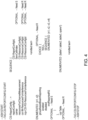
- TS 38.331 ["Radio Resource Control (RRC); Protocol specification", 3GPP] presents CSI-ReportConfig information element illustrated at FIG. 4 .
- a UE may have the option to report beam pairs that it can receive simultaneously.
- the beam pairs may be selected from a single transmission and reception point (TRP) or multiple TRPs, but Rel-17 feMIMO (further enhanced multiple in multiple out) discussions are ongoing to consider pairs of beams from different TRPs.
- TRP transmission and reception point
- Rel-17 feMIMO further enhanced multiple in multiple out
- these beam reporting features may, to some extent, help handling the problem with IAB nodes that simultaneous transmission may result in one or more transmissions to not be successfully received.
- this IAB problem may require a different solution than that which may be implied by UE group-based beam reporting or non-group based beam reporting, as supporting multiplexing case #B (i.e.
- simultaneous MT-Rx/DU-Rx) together with intra-frequency DC may additionally require alignment of the simultaneous reception of MT and DU beams.
- MT beam availability may change depending on which child node or UE is scheduled by the IAB DU at a given instant.
- a solution for this problem may also go beyond the intra-frequency DC scenario and be generally applicable for case #B operation, as simultaneous reception of MT and DU beam may be supported in the future.
- the example arrangements described may be applicable in both the single parent scenario and the multi-parent scenario.
- the IAB node consists of four panels (panel #1, panel #2, panel #3, panel #4), each directed towards a different direction.
- an IAB node may comprise more or fewer panels arranged in a similar or different configuration.
- the IAB node may use either one fixed panel (covers only one direction) or a few panels (covers more directions) to serve the child nodes/UEs (e.g. child node #1, child node #2) within its vicinity and may also maintain a connection towards/with parents (e.g. parent #1, parent #2) using the same set of panels.
- the intra-frequency DC support may use one or more of the following beam pairs: (x1, y1), (x2, y1), (x3, y1), (x3, y2), (x3, y3). These beam pairs may be viable because they enable parent #1 and parent #2 beams to be received with different panels.
- Parent #1 transmits beams x1 and x2 towards panel #1, and beam x3 towards panel #4.
- Parent #2 transmits beam y1 towards panel #2, and beams y2 and y3 towards panel #1.
- beam x1 of Parent #1 and beam y1 of Parent #2 may be received simultaneously with different panels; beam x2 of Parent #1 and beam y1 of Parent #2 may be received simultaneously with different panels; beam x3 of Parent #1 and beam y1 of Parent #2 may be received simultaneously with different panels; beam x3 of Parent #1 and beam y2 of Parent #2 may be received simultaneously with different panels; and beam x3 of Parent #1 and beam y3 of Parent #2 may be received simultaneously with different panels.
- beam x1 of Parent #1 and beam y2 of Parent #2 may not be received simultaneously, as they are both directed to the same panel of the IAB node, panel #1.
- FIG. 3 is intended to illustrate an example, not limit the scope of the present disclosure.
- the IAB node of FIG. 3 may be understood to comprise MT and DU. If Case #B operation (i.e. simultaneous MT-Rx/DU-Rx) is assumed at the IAB MT and IAB DU of the IAB node, the intra-frequency DC support may not be able to use all beam pairs reported above, as a panel used to serve a child node may not be used simultaneously for intra-frequency DC support. Also, the combination of beam pairs useable for intra-frequency DC support may change as the child node that IAB DU is scheduling in UL changes. For example, when child node #2 is served by the IAB node, panel #2 may not be used for beam y1 transmitted by/received from parent #1.
- Case #B operation i.e. simultaneous MT-Rx/DU-Rx
- beam y1 may be available for intra-frequency DC support when child node #1 is scheduled by the IAB DU and child node #2 is not, as child node #1 transmits towards panel #3 of IAB node in the example of FIG. 3 , towards which no parent is illustrated to transmit a beam.
- Example arrangements may provide a more efficient framework for beam reporting, which may solve the aforementioned concerns that simultaneous reception during intra- frequency DC and/or Case #B operation in general may result in an IAB node failing to receive a beam.
- beam reporting may be enhanced for IAB deployments such that the network gets more accurate feedback information to select the beams at parent node(s) for transmission so as to allow multiplexing Case #B (i.e. simultaneous MT-Rx/DU-Rx) to be enabled at the IAB node.
- multiplexing Case #B i.e. simultaneous MT-Rx/DU-Rx
- the beam reporting from the IAB node to the parent/network may carry additional information representing the multiplexing mode, restrictions applied when supporting a multiplexing mode, and/or any other details that may allow the network/parent to understand/determine changes of beam pairs (beams in single parent scenario) that may be received simultaneously at the IAB MT while the IAB DU is scheduled to receive transmission from a user equipment or child node.
- the additional information included in the beam reporting from the IAB node may be used by the network to decide/restrict the beams used for DL transmission towards IAB MT, while enabling IAB DU to provide the possibility to schedule the UL transmission of a child node(s).
- the beam reporting may consider/include an indication of: a multiplexing mode; an indication of a lack of beam/panel restrictions; indication(s) with beam pairs based on beam measurements; beam pair(s) that are allowable; and/or reference beam pair(s).
- the IAB MT may report, as additional information included in the beam reporting, a multiplexing mode (TDM), an indication that there are no restrictions of use of beams/panels, and/or any other indication together with the beam pairs (e.g. using group-based beam reporting, or beams single parent scenario) based on beam measurements made at/with the IAB MT.
- TDM time division multiplexing
- the reported beam pairs (or beams) may be used as the reference beam pairs (or beams) for later updates.
- the IAB MT may be configured to report, as additional information included in the beam reporting, more than one beam pair (sufficient combinations) such that the parents have more than one beam pair that can be applied when supporting intra-frequency DC connectivity with any multiplexing mode.
- the reported beam pairs (or beams) may also be considered as reference beam pair(s) that the IAB MT supports.
- the reference beam pairs (or beams) may be fixed or updated with time depending on further measurements and reporting made by/with the IAB MT.
- the beam reporting may consider/include an indication of: a multiplexing mode; an indication of beam/panel restrictions; indication(s) without beam pairs based on beam measurements; and/or change of beam pairs.
- the IAB MT may report, as additional information included in the beam reporting, a multiplexing mode (SDM), an indication that there are certain restrictions of use of beams/panels, and/or any other indication, with or without beam pairs (e.g. using group-based beam reporting) (beams in single parent scenario), based on beam measurements made at/with the IAB MT.
- SDM multiplexing mode
- the IAB MT may determine the changes/restrictions on beam pairs (beams) based on the use of IAB DU panels to serve one or more child node(s). In another reporting variant, with or without exact beam measurement, the IAB MT may report, as additional information included in the beam reporting, the changes of beam pairs (beams) compared to previously reported beam pair(s)/beam(s) or compared to reference beam pair(s)/reference beam(s) when using TDM mode.
- the changes of beam pairs may be reported again to reflect the changes that have occurred due to the different child node (applying the earlier method).
- the above beam reporting enhancement (of including additional information that may enable a network to determine changes to beam pairs that may be received simultaneously at the IAB MT) may use a group-based beam measurement and reporting framework, where pairs of beams that can be received simultaneously may be reported by the IAB MT using one or more variants of the above described additional information.
- the above beam reporting enhancement (of including additional information that may enable a network to determine changes to beam pairs that may be received simultaneously at the IAB MT) may use a legacy beam measurement and reporting framework, where pairs of beams that can be received simultaneously may be reported by the IAB MT using one or more variants of the above described additional information.
- an IAB node is illustrated as having four panels, Panel #1, Panel #2, Panel #3, and Panel #4.
- Parent #1 may be configured to transmit to panels #1 and #4 of the IAB node.
- Parent #2 may be configured to transmit to panels #1 and #2 of the IAB node.
- Child node #1 may be configured to transmit to Panel #3.
- Child node #2 may be configured to transmit to Panel #2.
- Child node #3 may be configured to transmit to Panel #4.
- the IAB node may be configured to receive transmissions from: Parent #1 and Parent #2 with panel #1; Parent #2 and Child node #2 with panel #2; Child node #1 with panel #3; and Parent #1 and Child node #3 with panel #4.
- beam measurements and reporting may indicate one or more of the following reference beam pairs: (x1, y1), (x2, y1), (x3, y1), (x3, y2), (x3, y3).
- the beam pairs that may be reported to parent(s)/the network may be determined based, at least partially, on the child node(s) from which the IAB node is scheduled to receive uplink transmission.
- the reference pairs may include (x1, y1), (x2, y1), (x3, y1), (x3, y2), and (x3, y3).
- the reference pairs may include (x1, y1), (x2, y1), (x3, y1), (x3, y2), (x3, y3).
- scheduling of child node #1 might not result in a change in the reference pairs.
- the IAB-MT may or may not update the parent node(s) when child node scheduling does not result in a change in the reference pairs. However, other scheduling by the IAB-DU may result in an update to the reference pairs.
- the reference pairs may be updated to include (x3, y2) and (x3, y3).
- beam pairs (x1, y1), (x2, y1), and (x3, y1) may not be suitable when child node #2 is scheduled by IAB-DU.
- the reference pairs may be updated to include (x1, y1) and (x2, y1).
- beam pairs (x3, y1), (x3, y2), and (x3, y3) may not be suitable when child node #3 is scheduled by IAB-DU.
- the reference pairs may updated to not include any beam pairs.
- beam pairs (x1, y1), (x2, y1), (x3, y1), (x3, y2), and (x3, y3) may not be suitable when child nodes #2 and #3 are scheduled by IAB-DU.
- the IAB node is connected to both parent #1 and #2 in the scenario illustrated at FIG. 5 .
- the IAB node may only be connected to parent #2.
- the reference pair may be updated to only include beam pairs using parent #2 beams y2 and y3, as FIG. 5 illustrates that both parent #2 beam y1 and child node #2 beam are directed to panel #2.
- the IAB node may include, in beam reporting, additional information indicating that the beam directed to panel #2, y1, may not be used in Case #B (i.e. simultaneous MT-Rx/DU-Rx) so as to enable reception at the IAB node from child node #2.
- Case #B i.e. simultaneous MT-Rx/DU-Rx
- Other combinations of scheduled reception from parent node(s) and child node(s) may be possible.
- measurement and reporting might not always be carried out such that all details should be reported.
- beam measurement may or may not be carried out when a child node is scheduled by the IAB-DU.
- reporting may or may not be carried out when a child node is scheduled by the IAB-DU.
- methods of optimizing feedback overhead are not discussed in detail, as such mechanisms are well known (e.g. bit maps).
- the beam pairs suitable for TDM might not change much in comparison to a mobility case. Accordingly, in an example arrangement, beam measurements and reporting might only be considered assuming TDM operation (i.e. infrequent updates), and frequent updates, depending on the panel use/child node scheduling, may report the changes to the reported beam pairs. As IAB nodes may therefore not waste effort on frequent beam measurement and reporting, we expect efficient simultaneous operation for intra-frequency DC and Case #B (i.e. simultaneous MT-Rx/DU-Rx) at the IAB node.
- TDM operation i.e. infrequent updates
- frequent updates depending on the panel use/child node scheduling
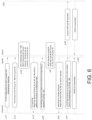
- FIG. 6 illustrated is an example signaling diagram on enhanced beam reporting, according to example described arrangements, for SDM operation with a single parent node.
- the IAB node is illustrated as an IAB-MT, which communicates with a parent node, and an IAB-DU, which communicates with a child node.
- IAB-MT + IAB-DU only one parent node is linked to the IAB node.
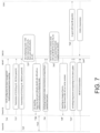
- IAB-MT + IAB-DU An example in which more than one parent node is linked to the IAB node (IAB-MT + IAB-DU) is described below with reference to FIG. 7 .
- the parent node #1 may configure the IAB-MT with channel state information (CSI) reporting configuration(s) that may enable beam reporting/management.
- CSI channel state information
- associated reference signal(s) (RS) for the beam(s) may also be indicated.
- parent #1 may transmit associated channel state information reference signal(s) (CSI-RS) resources (with corresponding beams) to the IAB-MT.
- CSI-RS channel state information reference signal(s)
- NZP non-zero power
- the corresponding beams may comprise beams #1-#8 of parent #1.
- the IAB-MT may perform beam measurement(s). For example, the IAB-MT may use two panels for CSI-RS measurements, assuming that simultaneously reception at the IAB MT and DU is not required.
- the IAB node may determine that the IAB multiplexing mode is TDM. The IAB node may determine, based on beam measurement, that beams #1, #2, and #3 can be received with panel #1; that beams #4, #5, and #6 can be received with panel #2; and that beams #7 and #8 may not be received by any panel.
- the IAB-MT may report the beam reporting/measurement(s) (e.g. via CSI reporting) towards the network (i.e. parent #1) with the additional information as described above.
- the additional information may include an indication of the TDM mode of the IAB node, and/or an indication of the acceptable beams #1-#6 for transmission from parent #1, etc.
- parent #1 may activate/use the reported beam(s), which may be in the form of transmission configuration indicator (TCI) states associated with received CRI, to be used for control and/or data channel(s).
- TCI transmission configuration indicator
- the parent #1 may activate one or more of beams #1-#6.
- parent #1 may perform data transmission to the IAB node using one or more of the beams reported with CSI-RS (i.e. beams #1-#6).
- the IAB-DU may decide to schedule one or more child node(s) with the Case #B (i.e. simultaneous MT-Rx/DU-Rx) SDM Rx multiplexing mode with IAB-MT, and may pre-determine the panel (beams) to be used to serve the child node.
- the IAB-DU may decide to use panel #2 to enable reception from a child node. Accordingly, while the child node is scheduled, it may not be possible to simultaneously receive beams #4-#6 with panel #2 from parent #1.
- the IAB-MT may report beam reporting (e.g. via CSI reporting or any other reporting method) towards the network (i.e. parent #1) with the additional information.
- the additional information may include restrictions applied for SDM operation as discussed above.
- the additional information may include an indication that beams #4, #5, and #6 may not be received by the IAB-MT.
- the additional information may also include an indication that the multiplexing mode is SDM.
- the IAB-DU may include an indication that panel #2 will be used for reception from the child node.
- parent #1 may activate/use only the reported beams indicated by the latest update, in the form of TCI states to be used, for control and data.
- Parent #1 may activate one or more of the beams that are not restricted, i.e. beams #1-#3.
- the IAB-MT may or may not get/receive an additional activation command for TCI states.
- the IAB-DU may schedule UL transmission(s) such that IAB node can operate in Case #B mode (i.e. simultaneous MT-Rx/DU-Rx).
- the IAB-DU may transmit to the child node an UL grant with Case #B operation.
- parent #1 may perform downlink transmission to the IAB-MT, and the child node may perform uplink transmission to the IAB-DU, simultaneously (i.e. during a same slot or time period).
- Each transmission may be received by the IAB node because the transmissions are non-overlapping, i.e. received with different panels of the IAB node.
- the IAB node is illustrated as an IAB-MT, which communicates with a parent node, and an IAB-DU, which communicates with a child node.
- IAB-MT + IAB-DU two parent nodes are linked to the IAB node (IAB-MT + IAB-DU), parent #1 and parent #2.
- parent #1 may transmit a CSI-RS configuration for beam management to the IAB-MT.
- the configuration may enable group-based beam reporting.
- associated reference signal(s) (RS) for the beam(s) may also be indicated.
- parent #1 may transmit associated channel state information reference signal(s) (CSI-RS) resources (with corresponding beams) to the IAB-MT.
- CSI-RS channel state information reference signal(s)
- the corresponding beams may comprise beams #1-#4 of parent #1.
- parent #2 may transmit associated CSI-RS to the IAB-MT.
- These CSI-RS may comprise non-zero power (NZP) CSI-RS.
- the corresponding beams may comprise beams #5-#8 of parent #2.
- the IAB-MT may perform beam measurement(s).
- the IAB node may determine that the IAB multiplexing mode is TDM.
- the IAB node may determine, based on beam measurement, that beam pairs (#1, #5), (#3, #7), and (#2, #7) are appropriate (i.e. these beam pairs will allow for simultaneous reception of both parent #1 and parent #2).
- the IAB-MT may report the beam reporting/measurement(s) (e.g. via CSI reporting) towards the network (i.e. parent #1) with the additional information as described above.
- the additional information may include an indication of the TDM mode of the IAB node, and/or an indication of the acceptable beam pairs ((#1, #5), (#3, #7), (#2, #7)) for transmission from parents #1 and #2, etc.
- Parent #1 may forward this beam reporting, including the additional information, to parent #2 at 735.
- both parent #1 and parent #2 may activate/use the reported beam(s), which may be in the form of transmission configuration indicator (TCI) states associated with received CRI, to be used for control and/or data channel(s).
- TCI transmission configuration indicator
- the parent #1 may activate one or more of beams #1, #2, and/or #3
- parent #2 may activate one or more of beams #5 and/or #7.
- parents #1 and/or #2 may perform data transmission to the IAB node using one or more of the beams reported with CSI-RS (i.e. beams #1-#3, #5, and/or #7).
- the additional information may include restrictions applied for SDM operation, as discussed above.
- the additional information may include an indication that the multiplexing mode is SDM.
- the additional information may include an indication that transmissions with beam pair (#3, #7) may not be received by the IAB-MT.
- the IAB-MT may include an indication of a panel that will be used for reception from the child node. Parent #1 may forward this beam reporting, including the additional information, to parent #2.
- parent #1 when there are additional information(s) available at the parent #1 about the restricted panel at the IAB node, and if beam #7 may still be used for transmission only using parent #2, parent #1 might not forward this beam reporting to parent #2, but parent #1 may restrain using beam #1.
- both parent #1 and parent #2 may activate/use only the reported beams indicated by the latest update, in the form of TCI states to be used, for control and data.
- the parent #1 may activate one or more of beams #1 and/or #2
- parent #2 may activate one or more of beams #5 and/or #7.
- the IAB-MT may or may not get/receive an additional activation command for TCI states.
- the IAB-DU may schedule UL transmission(s) such that IAB node can operate in Case #B mode (i.e. simultaneous MT-Rx/DU-Rx).
- the IAB-DU may transmit to the child node an UL grant with Case #B operation.
- parent #1 and parent #2 may perform downlink transmission to the IAB-MT, and the child node may perform uplink transmission to the IAB-DU, simultaneously (i.e. during a same slot or time period).
- Each transmission may be received by the IAB node because the transmissions are non-overlapping, i.e. received with different panels of the IAB node.
- a technical effect of example embodiments of the present disclosure may be to ensure that a parent node will not transmit to an IAB node with a beam that may interfere with IAB node reception of a beam scheduled to be received from a child node.
- FIG. 8 illustrates the potential steps of an example method 800.
- the example method 800 may include performing, with a first node, beam measurement for downlink beams received with the first node from at least one second node, 810; scheduling, with the first node, at least one third node for uplink transmission to the first node, 820; determining, with the first node, one or more of the downlink beams that can be received simultaneously with a beam of the at least one third node based, at least partially, on the scheduling of the at least one third node and the performing of the beam measurement, 830; and transmitting, with the first node, results of the performed beam measurement, wherein the results comprise an indication of the one or more determined downlink beams that can be received simultaneously with the beam of the at least one third node, 840.
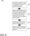
- FIG. 9 illustrates the potential steps of an example method 900.
- the example method 900 may include transmitting, to a first node, an indication of one or more resources a second node is configured to use for downlink transmission, 910; receiving, from the first node, beam reporting for the one or more resources, wherein the beam reporting comprises an indication of at least one resource of the one or more resources that can be received with the first node, 920; activating one or more of the at least one indicated resource, 930; and performing downlink transmission, to the first node, with the one or more activated resources, 940.
- an example method comprising: performing, with a first node, beam measurement for downlink beams received with the first node from at least one second node; scheduling, with the first node, at least one third node for uplink transmission to the first node; determining, with the first node, one or more of the downlink beams that can be received simultaneously with a beam of the at least one third node based, at least partially, on the scheduling of the at least one third node and the performing of the beam measurement; and transmitting, with the first node, results of the performed beam measurement, wherein the results may comprise an indication of the one or more determined downlink beams that can be received simultaneously with the beam of the at least one third node.
- the example method may further comprise: receiving, with the first node a configuration from the at least one second node, wherein the transmitting of the results of the performed beam management may be based, at least partially, on the received configuration.
- the first node may comprise an integrated access and backhaul node divided into a mobile termination and a distributed unit, wherein the transmitting with the first node may be performed with the mobile termination, wherein the scheduling of the at least one third node may be performed with the distributed unit.
- the example method may further comprise: simultaneously receiving, with the first node, a downlink beam from at least one of the at least one second node and an uplink beam from at least one of the at least one third node.
- the determining of the one or more of the downlink beams that can be received simultaneously with the beam of the at least one third node may be based, at least partially, on a reception panel configuration of the first node.
- the transmitting of the results of the performed beam measurement may further comprise transmitting at least one of: a multiplexing mode of the first node, one or more restrictions for the downlink beams, an indication that there is no restriction for the downlink beams, an indication of one or more reference beams, an indication of one or more reference beam pairs, a beam pair configured to support intra-frequency dual connectivity, or an indication based on the performing of the beam measurement.
- the first node may be operating in one of: a time division multiplexing mode, or a spatial division multiplexing mode.
- the example method may further comprise: transmitting, to the at least one third node, an uplink grant configuration, wherein the determining of the one or more of the downlink beams that can be received simultaneously with the beam of the at least one third node may be based, at least partially, on one or more panels of the first node indicated with the uplink grant configuration.
- the downlink beams and the beam of the at least one third node may be associated with frequencies that overlap.
- the first node may be configured to operate in an intra-frequency dual connectivity mode.
- the transmitting of the results of the performed beam measurement may comprise transmitting the results to at least one of the at least one second node.
- an apparatus may comprise: at least one processor; and at least one memory including computer program code; the at least one memory and the computer program code configured to, with the at least one processor, cause the apparatus to: perform beam measurement for downlink beams received with the apparatus from at least one second node; schedule at least one third node for uplink transmission to the apparatus; determine one or more of the downlink beams that can be received simultaneously with a beam of the at least one third node based, at least partially, on the scheduling of the at least one third node and the performing of the beam measurement; and transmit results of the performed beam measurement, wherein the results may comprise an indication of the one or more determined downlink beams that can be received simultaneously with the beam of the at least one third node.
- the example apparatus may be further configured to: receive a configuration from the at least one second node, wherein the transmitting of the results of the performed beam management is based, at least partially, on the received configuration.
- the example apparatus may be further configured to: simultaneously receive a downlink beam from at least one of the at least one second node and an uplink beam from at least one of the at least one third node.
- Determining the one or more of the downlink beams that can be received simultaneously with the beam of the at least one third node may be based, at least partially, on a reception panel configuration of the apparatus.
- Transmitting the results of the performed beam measurement may further comprise transmitting at least one of: a multiplexing mode of the apparatus one or more restrictions for the downlink beams, an indication that there is no restriction for the downlink beams, an indication of one or more reference beams, an indication of one or more reference beam pairs, a beam pair configured to support intra-frequency dual connectivity, or an indication based on the performing of the beam measurement.
- the example apparatus may be further configured to: operate in one of: a time division multiplexing mode, or a spatial division multiplexing mode.
- the example apparatus may be further configured to: transmit, to the at least one third node, an uplink grant configuration, wherein the determining of the one or more of the downlink beams that can be received simultaneously with the beam of the at least one third node may be based, at least partially, on one or more panels of the apparatus indicated with the uplink grant configuration.
- the downlink beams and the beam of the at least one third node may be associated with frequencies that overlap.
- the example apparatus may be further configured to: operate in an intra-frequency dual connectivity mode.
- Transmitting the results of the performed beam measurement may comprise transmitting the results to at least one of the at least one second node.
- an apparatus may comprise: circuitry configured to perform: performing, with a first node, beam measurement for downlink beams received with the first node from at least one second node; scheduling, with the first node, at least one third node for uplink transmission to the first node; determining, with the first node, one or more of the downlink beams that can be received simultaneously with a beam of the at least one third node based, at least partially, on the scheduling of the at least one third node and the performing of the beam measurement; and transmitting, with the first node, results of the performed beam measurement, wherein the results may comprise an indication of the one or more determined downlink beams that can be received simultaneously with the beam of the at least one third node.
- circuitry also covers an implementation of merely a hardware circuit or processor (or multiple processors) or portion of a hardware circuit or processor and its (or their) accompanying software and/or firmware.
- circuitry also covers, for example and if applicable to the particular claim element, a baseband integrated circuit or processor integrated circuit for a mobile device or a similar integrated circuit in server, a cellular network device, or other computing or network device.
- an apparatus may comprise means for performing: performing beam measurement for downlink beams received with the apparatus from at least one second node; scheduling at least one third node for uplink transmission to the apparatus; determining one or more of the downlink beams that can be received simultaneously with a beam of the at least one third node based, at least partially, on the scheduling of the at least one third node and the performing of the beam measurement; and transmitting results of the performed beam measurement, wherein the results may comprise an indication of the one or more determined downlink beams that can be received simultaneously with the beam of the at least one third node.
Landscapes
- Engineering & Computer Science (AREA)
- Signal Processing (AREA)
- Computer Networks & Wireless Communication (AREA)
- Mobile Radio Communication Systems (AREA)
Claims (12)
- Verfahren, das Folgendes umfasst:Durchführen (810) einer Strahlmessung für Downlinkstrahlen, die mit einem ersten Knoten empfangen werden, mit dem ersten Knoten von mindestens einem zweiten Knoten;Planen (820) von mindestens einem dritten Knoten für eine Uplinkübertragung zum ersten Knoten mit dem ersten Knoten;Bestimmen (830) von einem oder mehreren Downlinkstrahlen, die gleichzeitig mit einem Strahl des mindestens einen dritten Knotens empfangen werden können, mit dem ersten Knoten mindestens teilweise auf Basis des Planens des mindestens einen dritten Knotens und des Durchführens der Strahlmessung undÜbertragen (840) von Ergebnissen der durchgeführten Strahlmessung mit dem ersten Knoten, wobei die Ergebnisse eine Anzeige des einen oder der mehreren bestimmten Downlinkstrahlen umfassen, die gleichzeitig mit dem Strahl des mindestens einen dritten Knotens empfangen werden können.
- Vorrichtung, die Folgendes umfasst:Mittel zum Durchführen (810) einer Strahlmessung für Downlinkstrahlen, die mit der Vorrichtung von mindestens einem zweiten Knoten empfangen werden;Mittel zum Planen (820) von mindestens einem dritten Knoten für eine Uplinkübertragung zur Vorrichtung;Mittel zum Bestimmen (830) von einem oder mehreren Downlinkstrahlen, die gleichzeitig mit einem Strahl des mindestens einen dritten Knotens empfangen werden können, mindestens teilweise auf Basis des Planens des mindestens einen dritten Knotens und des Durchführens der Strahlmessung undMittel zum Übertragen (840) von Ergebnissen der durchgeführten Strahlmessung, wobei die Ergebnisse eine Anzeige des einen oder der mehreren bestimmten Downlinkstrahlen umfassen, die gleichzeitig mit dem Strahl des mindestens einen dritten Knotens empfangen werden können.
- Vorrichtung nach Anspruch 2, die ferner Folgendes umfasst:
Mittel zum Empfangen einer Auslegung von dem mindestens einen zweiten Knoten, wobei das Übertragen der Ergebnisse der durchgeführten Strahlmessung mindestens teilweise auf der empfangenen Auslegung basiert. - Vorrichtung nach Anspruch 2 oder 3, die ferner Folgendes umfasst:
Mittel zum gleichzeitigen Empfangen eines Downlinkstrahls von mindestens einem des mindestens einen zweiten Knotens und eines Uplinkstrahls von mindestens einem des mindestens einen dritten Knotens. - Vorrichtung nach einem der Ansprüche 2 bis 4, wobei das Bestimmen des einen oder der mehreren Downlinkstrahlen, die gleichzeitig mit dem Strahl des mindestens einen dritten Knotens empfangen werden können, mindestens teilweise auf einer Empfangspaneelauslegung der Vorrichtung basiert.
- Vorrichtung nach einem der Ansprüche 2 bis 5, wobei das Übertragen der Ergebnisse der durchgeführten Strahlmessung ferner das Übertragen von mindestens einem von Folgendem umfasst:einem Multiplexingmodus der Vorrichtungeiner oder mehreren Einschränkungen für die Downlinkstrahlen,einer Anzeige, dass für die Downlinkstrahlen keine Einschränkung vorliegt, einer Anzeige von einem oder mehreren Referenzstrahlen,einer Anzeige von einem oder mehreren Referenzstrahlpaaren,einem Strahlpaar, das dazu ausgelegt ist, eine duale Intrafrequenzkonnektivität zu unterstützen, oder einer Anzeige, die auf dem Durchführen der Strahlmessung basiert.
- Vorrichtung nach einem der Ansprüche 2 bis 6, die ferner Mittel zum Betreiben in einem von Folgendem umfasst:
einem Zeitmultiplexingmodus oder einem Raummultiplexingmodus. - Vorrichtung nach einem der Ansprüche 2 bis 7, die ferner Folgendes umfasst:
Mittel zum Übertragen einer Uplinkgewährungsauslegung zu dem mindestens einen dritten Knoten, wobei das Bestimmen des einen oder der mehreren Downlinkstrahlen, die mit dem Strahl des mindestens einen dritten Knotens gleichzeitig empfangen werden können, mindestens teilweise auf einem oder mehreren Paneelen der Vorrichtung basiert, die mit der Uplinkgewährungsauslegung angezeigt werden. - Vorrichtung nach einem der Ansprüche 2 bis 8, wobei die Downlinkstrahlen und der Strahl des mindestens einen dritten Knotens mit Frequenzen verknüpft sind, die sich überlappen.
- Vorrichtung nach einem der Ansprüche 2 bis 9, die ferner Mittel zum Betreiben in einem dualen Intrafrequenzkonnektivitätsmodus umfassen.
- Vorrichtung nach einem der Ansprüche 2 bis 10, wobei das Übertragen der Ergebnisse der durchgeführten Strahlmessung das Übertragen der Ergebnisse zu mindestens einem des mindestens einen zweiten Knotens umfasst.
- Nichttransitorisches computerlesbares Medium, das darauf gespeicherte Programmanweisungen umfasst, die, wenn sie mit mindestens einem Prozessor ausgeführt werden, den mindestens einen Prozessor veranlassen, das Verfahren nach Anspruch 1 durchzuführen.
Applications Claiming Priority (2)
| Application Number | Priority Date | Filing Date | Title |
|---|---|---|---|
| US202063094491P | 2020-10-21 | 2020-10-21 | |
| PCT/EP2021/078000 WO2022084079A1 (en) | 2020-10-21 | 2021-10-11 | Beam reporting enhancement for simultaneous iab reception |
Publications (3)
| Publication Number | Publication Date |
|---|---|
| EP4233181A1 EP4233181A1 (de) | 2023-08-30 |
| EP4233181C0 EP4233181C0 (de) | 2025-01-22 |
| EP4233181B1 true EP4233181B1 (de) | 2025-01-22 |
Family
ID=78086381
Family Applications (1)
| Application Number | Title | Priority Date | Filing Date |
|---|---|---|---|
| EP21790193.3A Active EP4233181B1 (de) | 2020-10-21 | 2021-10-11 | Strahlmeldungsverbesserung für simultanen iab-empfang |
Country Status (7)
| Country | Link |
|---|---|
| US (1) | US20230421316A1 (de) |
| EP (1) | EP4233181B1 (de) |
| JP (1) | JP7568846B2 (de) |
| CN (1) | CN116636153A (de) |
| ES (1) | ES3015067T3 (de) |
| PL (1) | PL4233181T3 (de) |
| WO (1) | WO2022084079A1 (de) |
Families Citing this family (5)
| Publication number | Priority date | Publication date | Assignee | Title |
|---|---|---|---|---|
| WO2022086431A1 (en) * | 2020-10-23 | 2022-04-28 | Telefonaktiebolaget Lm Ericsson (Publ) | Technique for allocating spatial radio resources for an integrated access and backhaul node |
| CN114531697A (zh) * | 2020-11-23 | 2022-05-24 | 维沃移动通信有限公司 | 传输处理方法、装置及通信设备 |
| US12289781B2 (en) * | 2021-01-11 | 2025-04-29 | Electronics And Telecommunications Research Institute | Method and apparatus for dual connectivity management in wireless communication system |
| US12149969B2 (en) * | 2021-07-01 | 2024-11-19 | Apple Inc. | Method for CSI and beam report enhancement for multi-TRP full duplex |
| US12376096B2 (en) * | 2021-08-13 | 2025-07-29 | Qualcomm Incorporated | Signaling enhancements for simultaneous multiplexing in an integrated access and backhaul network |
Family Cites Families (8)
| Publication number | Priority date | Publication date | Assignee | Title |
|---|---|---|---|---|
| US10986644B2 (en) * | 2017-10-12 | 2021-04-20 | Qualcomm Incorporated | Beam management schemes |
| FI20185326A1 (en) * | 2018-04-06 | 2019-10-07 | Nokia Technologies Oy | Monitoring in wireless backhaul networks |
| US10700775B2 (en) * | 2018-05-11 | 2020-06-30 | At&T Intellectual Property I, L.P. | Resource coordination for integrated access and backhaul |
| US10623067B2 (en) * | 2018-05-11 | 2020-04-14 | At&T Intellectual Property I, L.P. | Enhanced timing advance scheme to support MU-MIMO in integrated access and backhaul |
| US11089622B2 (en) * | 2018-05-29 | 2021-08-10 | Qualcomm Incorporated | Supporting scheduling plan indications |
| US11979764B2 (en) * | 2018-08-10 | 2024-05-07 | Apple Inc. | Inter-integrated access and backhaul node cross-link interface measurement and reporting |
| CN111436145A (zh) * | 2019-01-11 | 2020-07-21 | 华为技术有限公司 | 资源配置的方法和装置 |
| CN113994726A (zh) * | 2019-06-18 | 2022-01-28 | 株式会社Ntt都科摩 | 无线通信节点及无线通信方法 |
-
2021
- 2021-10-11 ES ES21790193T patent/ES3015067T3/es active Active
- 2021-10-11 WO PCT/EP2021/078000 patent/WO2022084079A1/en not_active Ceased
- 2021-10-11 CN CN202180085896.6A patent/CN116636153A/zh active Pending
- 2021-10-11 JP JP2023524559A patent/JP7568846B2/ja active Active
- 2021-10-11 US US18/249,878 patent/US20230421316A1/en active Pending
- 2021-10-11 EP EP21790193.3A patent/EP4233181B1/de active Active
- 2021-10-11 PL PL21790193.3T patent/PL4233181T3/pl unknown
Also Published As
| Publication number | Publication date |
|---|---|
| PL4233181T3 (pl) | 2025-03-17 |
| EP4233181A1 (de) | 2023-08-30 |
| EP4233181C0 (de) | 2025-01-22 |
| ES3015067T3 (en) | 2025-04-29 |
| JP2023546936A (ja) | 2023-11-08 |
| WO2022084079A1 (en) | 2022-04-28 |
| JP7568846B2 (ja) | 2024-10-16 |
| US20230421316A1 (en) | 2023-12-28 |
| CN116636153A (zh) | 2023-08-22 |
Similar Documents
| Publication | Publication Date | Title |
|---|---|---|
| EP4233181B1 (de) | Strahlmeldungsverbesserung für simultanen iab-empfang | |
| EP4274134A2 (de) | Erstellung eines harq-codebuchs mit rückkopplungsaktivierung/-deaktivierung pro harq-prozess | |
| US20210022136A1 (en) | Method and device for configuring relay resource | |
| JP2020507282A (ja) | 5g/lteデュアルコネクティビティ | |
| US20250105895A1 (en) | Method for operation of apparatus in wireless communication system, and apparatus using said method | |
| CN114451020B (zh) | 面板特定ul功率控制 | |
| US20220124652A1 (en) | IAB Timing Delta MAC CE Enhancement For Case #6 Timing Support | |
| JP2022511267A (ja) | 通信のための方法、デバイス及びプログラム | |
| US20230403662A1 (en) | IAB Timing Delta MAC CE Enhancement for Case #6 Timing Support | |
| EP4106468A1 (de) | Betriebsverfahren für einen iab-knoten in einem drahtlosen kommunikationssystem und vorrichtung unter verwendung desselben | |
| US20230318695A1 (en) | Repeater for downlink transmission and uplink transmission | |
| EP3005812A1 (de) | Verfahren und vorrichtung zur konfiguration von zeitplanungsperioden auf basis von informationen über den betriebsmodus | |
| EP4503698A1 (de) | Verfahren und vorrichtung zur durchführung von adaptiver strahlformung in einem drahtloskommunikationssystem | |
| US12348278B2 (en) | UE self-calibration in communication systems | |
| US20250267053A1 (en) | Method and device for resource allocation in wireless communication system | |
| EP4150782A2 (de) | Aktivierung von strahldiversität zur uplink-steuerungsinformationsübertragung auf einem physikalischen uplink-steuerkanal | |
| US20250294463A1 (en) | Ul srs power control under multi-trp operation for c-jt | |
| US20250062886A1 (en) | Device operation method and device using same in wireless communication system | |
| CN119111051A (zh) | 无线通信系统中的装置的操作方法及利用所述方法的装置 | |
| WO2021194926A1 (en) | Ue split architecture with distributed tx/rx chains | |
| EP4593446A1 (de) | Strahlanzeigeverfahren und -vorrichtung in einem drahtloskommunikationssystem | |
| US20240306195A1 (en) | Adaptive listen-before-talk mode selection | |
| CN119072997A (zh) | 无线系统中的定时提前管理 | |
| CN119485775A (zh) | 用于通过ta获取的多trp方法 | |
| CN120835310A (zh) | 通信方法及相关装置 |
Legal Events
| Date | Code | Title | Description |
|---|---|---|---|
| STAA | Information on the status of an ep patent application or granted ep patent |
Free format text: STATUS: UNKNOWN |
|
| STAA | Information on the status of an ep patent application or granted ep patent |
Free format text: STATUS: THE INTERNATIONAL PUBLICATION HAS BEEN MADE |
|
| PUAI | Public reference made under article 153(3) epc to a published international application that has entered the european phase |
Free format text: ORIGINAL CODE: 0009012 |
|
| STAA | Information on the status of an ep patent application or granted ep patent |
Free format text: STATUS: REQUEST FOR EXAMINATION WAS MADE |
|
| 17P | Request for examination filed |
Effective date: 20230522 |
|
| AK | Designated contracting states |
Kind code of ref document: A1 Designated state(s): AL AT BE BG CH CY CZ DE DK EE ES FI FR GB GR HR HU IE IS IT LI LT LU LV MC MK MT NL NO PL PT RO RS SE SI SK SM TR |
|
| DAV | Request for validation of the european patent (deleted) | ||
| DAX | Request for extension of the european patent (deleted) | ||
| GRAP | Despatch of communication of intention to grant a patent |
Free format text: ORIGINAL CODE: EPIDOSNIGR1 |
|
| STAA | Information on the status of an ep patent application or granted ep patent |
Free format text: STATUS: GRANT OF PATENT IS INTENDED |
|
| INTG | Intention to grant announced |
Effective date: 20240502 |
|
| GRAJ | Information related to disapproval of communication of intention to grant by the applicant or resumption of examination proceedings by the epo deleted |
Free format text: ORIGINAL CODE: EPIDOSDIGR1 |
|
| STAA | Information on the status of an ep patent application or granted ep patent |
Free format text: STATUS: REQUEST FOR EXAMINATION WAS MADE |
|
| GRAS | Grant fee paid |
Free format text: ORIGINAL CODE: EPIDOSNIGR3 |
|
| STAA | Information on the status of an ep patent application or granted ep patent |
Free format text: STATUS: GRANT OF PATENT IS INTENDED |
|
| GRAP | Despatch of communication of intention to grant a patent |
Free format text: ORIGINAL CODE: EPIDOSNIGR1 |
|
| INTC | Intention to grant announced (deleted) | ||
| INTG | Intention to grant announced |
Effective date: 20240923 |
|
| GRAA | (expected) grant |
Free format text: ORIGINAL CODE: 0009210 |
|
| STAA | Information on the status of an ep patent application or granted ep patent |
Free format text: STATUS: THE PATENT HAS BEEN GRANTED |
|
| AK | Designated contracting states |
Kind code of ref document: B1 Designated state(s): AL AT BE BG CH CY CZ DE DK EE ES FI FR GB GR HR HU IE IS IT LI LT LU LV MC MK MT NL NO PL PT RO RS SE SI SK SM TR |
|
| REG | Reference to a national code |
Ref country code: GB Ref legal event code: FG4D |
|
| REG | Reference to a national code |
Ref country code: CH Ref legal event code: EP |
|
| REG | Reference to a national code |
Ref country code: IE Ref legal event code: FG4D |
|
| REG | Reference to a national code |
Ref country code: DE Ref legal event code: R096 Ref document number: 602021025169 Country of ref document: DE |
|
| U01 | Request for unitary effect filed |
Effective date: 20250122 |
|
| U07 | Unitary effect registered |
Designated state(s): AT BE BG DE DK EE FI FR IT LT LU LV MT NL PT RO SE SI Effective date: 20250128 |
|
| REG | Reference to a national code |
Ref country code: GR Ref legal event code: EP Ref document number: 20250400408 Country of ref document: GR Effective date: 20250409 Ref country code: ES Ref legal event code: FG2A Ref document number: 3015067 Country of ref document: ES Kind code of ref document: T3 Effective date: 20250429 |
|
| PG25 | Lapsed in a contracting state [announced via postgrant information from national office to epo] |
Ref country code: RS Free format text: LAPSE BECAUSE OF FAILURE TO SUBMIT A TRANSLATION OF THE DESCRIPTION OR TO PAY THE FEE WITHIN THE PRESCRIBED TIME-LIMIT Effective date: 20250422 |
|
| PG25 | Lapsed in a contracting state [announced via postgrant information from national office to epo] |
Ref country code: NO Free format text: LAPSE BECAUSE OF FAILURE TO SUBMIT A TRANSLATION OF THE DESCRIPTION OR TO PAY THE FEE WITHIN THE PRESCRIBED TIME-LIMIT Effective date: 20250422 Ref country code: IS Free format text: LAPSE BECAUSE OF FAILURE TO SUBMIT A TRANSLATION OF THE DESCRIPTION OR TO PAY THE FEE WITHIN THE PRESCRIBED TIME-LIMIT Effective date: 20250522 |
|
| PG25 | Lapsed in a contracting state [announced via postgrant information from national office to epo] |
Ref country code: HR Free format text: LAPSE BECAUSE OF FAILURE TO SUBMIT A TRANSLATION OF THE DESCRIPTION OR TO PAY THE FEE WITHIN THE PRESCRIBED TIME-LIMIT Effective date: 20250122 |
|
| PG25 | Lapsed in a contracting state [announced via postgrant information from national office to epo] |
Ref country code: SM Free format text: LAPSE BECAUSE OF FAILURE TO SUBMIT A TRANSLATION OF THE DESCRIPTION OR TO PAY THE FEE WITHIN THE PRESCRIBED TIME-LIMIT Effective date: 20250122 |
|
| PGFP | Annual fee paid to national office [announced via postgrant information from national office to epo] |
Ref country code: GR Payment date: 20250911 Year of fee payment: 5 |
|
| PGFP | Annual fee paid to national office [announced via postgrant information from national office to epo] |
Ref country code: PL Payment date: 20250901 Year of fee payment: 5 |
|
| U20 | Renewal fee for the european patent with unitary effect paid |
Year of fee payment: 5 Effective date: 20250909 |
|
| PGFP | Annual fee paid to national office [announced via postgrant information from national office to epo] |
Ref country code: GB Payment date: 20250904 Year of fee payment: 5 |
|
| PGFP | Annual fee paid to national office [announced via postgrant information from national office to epo] |
Ref country code: CZ Payment date: 20250923 Year of fee payment: 5 |
|
| PG25 | Lapsed in a contracting state [announced via postgrant information from national office to epo] |
Ref country code: SK Free format text: LAPSE BECAUSE OF FAILURE TO SUBMIT A TRANSLATION OF THE DESCRIPTION OR TO PAY THE FEE WITHIN THE PRESCRIBED TIME-LIMIT Effective date: 20250122 |
|
| PLBE | No opposition filed within time limit |
Free format text: ORIGINAL CODE: 0009261 |
|
| STAA | Information on the status of an ep patent application or granted ep patent |
Free format text: STATUS: NO OPPOSITION FILED WITHIN TIME LIMIT |
|
| 26N | No opposition filed |
Effective date: 20251023 |
|
| PGFP | Annual fee paid to national office [announced via postgrant information from national office to epo] |
Ref country code: TR Payment date: 20251003 Year of fee payment: 5 |
|
| PGFP | Annual fee paid to national office [announced via postgrant information from national office to epo] |
Ref country code: ES Payment date: 20251107 Year of fee payment: 5 |