EP4233004B1 - Automatisiertes kalibrierungsverfahren eines systems mit einer externen augenverfolgungsvorrichtung und einer computervorrichtung - Google Patents
Automatisiertes kalibrierungsverfahren eines systems mit einer externen augenverfolgungsvorrichtung und einer computervorrichtung Download PDFInfo
- Publication number
- EP4233004B1 EP4233004B1 EP21801216.9A EP21801216A EP4233004B1 EP 4233004 B1 EP4233004 B1 EP 4233004B1 EP 21801216 A EP21801216 A EP 21801216A EP 4233004 B1 EP4233004 B1 EP 4233004B1
- Authority
- EP
- European Patent Office
- Prior art keywords
- camera
- computing device
- screen
- user
- eye
- Prior art date
- Legal status (The legal status is an assumption and is not a legal conclusion. Google has not performed a legal analysis and makes no representation as to the accuracy of the status listed.)
- Active
Links
Images


Classifications
-
- G—PHYSICS
- G06—COMPUTING OR CALCULATING; COUNTING
- G06T—IMAGE DATA PROCESSING OR GENERATION, IN GENERAL
- G06T7/00—Image analysis
- G06T7/70—Determining position or orientation of objects or cameras
-
- G—PHYSICS
- G06—COMPUTING OR CALCULATING; COUNTING
- G06T—IMAGE DATA PROCESSING OR GENERATION, IN GENERAL
- G06T7/00—Image analysis
- G06T7/80—Analysis of captured images to determine intrinsic or extrinsic camera parameters, i.e. camera calibration
- G06T7/85—Stereo camera calibration
-
- G—PHYSICS
- G06—COMPUTING OR CALCULATING; COUNTING
- G06T—IMAGE DATA PROCESSING OR GENERATION, IN GENERAL
- G06T7/00—Image analysis
- G06T7/20—Analysis of motion
- G06T7/246—Analysis of motion using feature-based methods, e.g. the tracking of corners or segments
- G06T7/248—Analysis of motion using feature-based methods, e.g. the tracking of corners or segments involving reference images or patches
-
- G—PHYSICS
- G06—COMPUTING OR CALCULATING; COUNTING
- G06T—IMAGE DATA PROCESSING OR GENERATION, IN GENERAL
- G06T7/00—Image analysis
- G06T7/20—Analysis of motion
- G06T7/285—Analysis of motion using a sequence of stereo image pairs
-
- G—PHYSICS
- G06—COMPUTING OR CALCULATING; COUNTING
- G06V—IMAGE OR VIDEO RECOGNITION OR UNDERSTANDING
- G06V40/00—Recognition of biometric, human-related or animal-related patterns in image or video data
- G06V40/10—Human or animal bodies, e.g. vehicle occupants or pedestrians; Body parts, e.g. hands
- G06V40/16—Human faces, e.g. facial parts, sketches or expressions
- G06V40/168—Feature extraction; Face representation
- G06V40/171—Local features and components; Facial parts ; Occluding parts, e.g. glasses; Geometrical relationships
-
- G—PHYSICS
- G06—COMPUTING OR CALCULATING; COUNTING
- G06V—IMAGE OR VIDEO RECOGNITION OR UNDERSTANDING
- G06V40/00—Recognition of biometric, human-related or animal-related patterns in image or video data
- G06V40/10—Human or animal bodies, e.g. vehicle occupants or pedestrians; Body parts, e.g. hands
- G06V40/18—Eye characteristics, e.g. of the iris
-
- H—ELECTRICITY
- H04—ELECTRIC COMMUNICATION TECHNIQUE
- H04N—PICTORIAL COMMUNICATION, e.g. TELEVISION
- H04N17/00—Diagnosis, testing or measuring for television systems or their details
- H04N17/002—Diagnosis, testing or measuring for television systems or their details for television cameras
-
- G—PHYSICS
- G06—COMPUTING OR CALCULATING; COUNTING
- G06T—IMAGE DATA PROCESSING OR GENERATION, IN GENERAL
- G06T2200/00—Indexing scheme for image data processing or generation, in general
- G06T2200/24—Indexing scheme for image data processing or generation, in general involving graphical user interfaces [GUIs]
-
- G—PHYSICS
- G06—COMPUTING OR CALCULATING; COUNTING
- G06T—IMAGE DATA PROCESSING OR GENERATION, IN GENERAL
- G06T2207/00—Indexing scheme for image analysis or image enhancement
- G06T2207/10—Image acquisition modality
- G06T2207/10004—Still image; Photographic image
- G06T2207/10012—Stereo images
-
- G—PHYSICS
- G06—COMPUTING OR CALCULATING; COUNTING
- G06T—IMAGE DATA PROCESSING OR GENERATION, IN GENERAL
- G06T2207/00—Indexing scheme for image analysis or image enhancement
- G06T2207/30—Subject of image; Context of image processing
- G06T2207/30196—Human being; Person
- G06T2207/30201—Face
-
- G—PHYSICS
- G06—COMPUTING OR CALCULATING; COUNTING
- G06T—IMAGE DATA PROCESSING OR GENERATION, IN GENERAL
- G06T2207/00—Indexing scheme for image analysis or image enhancement
- G06T2207/30—Subject of image; Context of image processing
- G06T2207/30204—Marker
-
- G—PHYSICS
- G06—COMPUTING OR CALCULATING; COUNTING
- G06T—IMAGE DATA PROCESSING OR GENERATION, IN GENERAL
- G06T2207/00—Indexing scheme for image analysis or image enhancement
- G06T2207/30—Subject of image; Context of image processing
- G06T2207/30244—Camera pose
Definitions
- the present invention relates to a method for automated calibration between an eye-tracking device and a computing device with a camera. This method enables to capture the gaze of a user on the screen of the computing device in real-time irrespective of the position of the eye-tracking device with respect to the computing device.
- Eye tracking has been solved by making use of multiple strategies.
- An eye tracking setup is generally composed of one or multiple cameras that capture the face and/or eyes and, in most common applications, with one or multiple screen such as a laptop screen or desktop screen.
- Most systems require to know what the positioning of the physical screens is with respect to the eye-tracking device configured to track the movement of the eyes of a user.
- US 2020174560 discloses a calibration method for a three-dimensional augmented reality and apparatus thereof.
- the calibration method includes determining a first conversion parameter representing a relationship between a coordinate system of an eye-tracking camera and a coordinate system of a calibration camera by capturing a physical pattern using the eye-tracking camera and the calibration camera, and determining a second conversion parameter representing a relationship between a coordinate system of a virtual screen and the coordinate system of the calibration camera and a size parameter representing a size of the virtual screen by capturing a virtual pattern displayed on the virtual screen using the calibration camera.
- the method according to US2020174560 therefore enables to accurately display a virtual object on a virtual screen at a point corresponding to a target position which intersects the gaze ray of the user tracked by the eye-tracking camera.
- US 2011/063403 A1 is a patent publication aiming at gaze tracking among other applications. US 2011/063403 A1 uses facial characteristics to determine the geometry of the cameras.
- Another aim of the present invention is to provide a method for a quick setup and an automated calibration of a system comprising an eye-tracking device and a computing device.
- these aims are achieved by means of a method for calibrating a system comprising an external eye-tracking device and a computing device and for capturing the gaze of a user on the screen of the computing device in real-time.
- the calibration of the system comprises: capturing with one or more cameras of the eye-tracking device at least of one image of landmarks of the face of the user to identify the 3D position of each landmark in the coordinate system (ECS) of said eye tracking device; capturing with a camera of the computing device the same landmarks of the face of the user in the image coordinate system (ICS) of the computing device camera to identify the 2D position of each landmark in the image coordinate system ICS; computing the 3D pose of the camera of the computing device, defined as the camera coordinate system (CCS), as a function of the 3D position and 2D position of each landmark respectively in the coordinate system ECS and in the coordinate system ICS, and computing the 3D pose of the screen of the computing device, defined as the screen coordinate system (SCS), as a function of the camera coordinate system and mechanical
- Capturing the gaze of a user on the screen of the computing device in real-time comprises: retrieving a gaze ray of the user with the eye-tracking device, and intersecting the gaze ray of the user with the plane of the screen of the computing device, as a function of the ECS and SCS parameters, to capture the gaze-on-screen in real-time.
- the gaze ray is retrieved within a time frame that is the same, different or overlapping a time frame during which the calibration of the system is performed.
- the 3D position and 2D position of each landmark are further used to compute the computing device camera intrinsic parameters, such as the focal length, principal point, and lens distortion parameters, by minimizing the reprojection error between 2D landmarks positions and the 2D projection of the 3D landmarks into the ICS as function of said intrinsic parameters.
- the step of determining the mechanical parameters describing how the screen is positioned with respect to the camera of the computing device uses a User Interface (UI) which prompts the user to indicate the position of said camera with respect to the screen of the computing device.
- UI User Interface
- the step of determining the mechanical parameters describing how the screen is positioned with respect to the camera of the computing device comprises retrieving, from a database comprising existing computing devices in the market, information on the location of the camera with respect to its screen to a specific computing device.
- the eye-tracking device and the computing device are assumed to be temporally stationary to compute the 3D pose of the screen of the computing device defined as the SCS through a frame-batch calibration by aggregating information from multiple temporal frames such that:
- a frame-batch calibration is conducted as a one-time calibration, in which the calibration parameters are fixed and reused without further adaptations when intersecting the gaze ray (d) of the user (P) with the plane of the screen of the computing device, as a function of the ECS and SCS parameters.
- the eye tracking device comprising an Inertial Measurement Unit (IMU).
- IMU Inertial Measurement Unit
- the calibration of the system is run again when the background has moved from the field of view of the camera of the computing device or the camera of the eye tracking device, using background features tracking techniques.
- the method further uses a UI for guiding the user for the calibration of the system.
- the UI is configured to:
- samples of landmarks of the user are continuously been collected by the one or more cameras of the eye tracking device.
- the 3D pose of the camera of the computing device with respect to the 3D pose of the eye tracking device is iteratively computed with the last N frames at different time intervals in order to capture the gaze-on-screen in real-time irrespective of the position of the eye-tracking device with respect to the computing device while the face of the user is in the field of view of both the eye tracking device and the camera of the computing device.
- the eye-tracking device comprises a depth-sensing camera to identify the 3D position of each landmark in the coordinate system ECS.
- the eye-tracking device comprises a multi-camera.
- the 3D position of each landmark in the coordinate system ECS is calculated using a stereo triangulation computer vision technique.
- the eye-tracking device comprises a 3D representation of a person's facial shape which is used to identify the 3D position of each landmark in the coordinate system ECS or CCS.
- the landmarks are facial features of the user corresponding to facial points such as eye corners, mouth corners and nose tip.
- the landmarks comprise any point which can be detected in both the eye tracking device camera as well as the computing device camera, a priori.
- Candidate points may be defined from image processing techniques to establish interest points.
- the camera of the computing device is an in-built or external camera.
- a user interface displays visual markers on the screen that can be used as a visual guide to the user on how to mount the external camera on the screen at a desired position. Alternatively, the user may move such visual markers to feedback into the system where the camera has been placed or where the camera has been built into the computing device.
- the eye-tracking device is a mobile phone.
- the present invention also relates a tangible computer product containing program code for causing a processor to execute the method as described above when said code is executed on said processor.
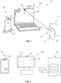
- Figures 1 and 2 schematically show an example of a system 10 comprising a computing device 12a, 12b and an eye-tracking device 16.
- the computing device may be for example a laptop computer 12a, a desktop computer 12b, or a tablet computer (not shown).
- the computing device comprises a built-in 2D camera 15 or, as an alternative, an external 2D camera (not shown) which can be positioned on the borders 14 of the screen 13 of a desktop computer 12b in an unambiguous manner such as a specific model with a specific mount with indications on its placement with respect to the screen of the computing device.
- the tracking device 16 is preferably a mobile device such as a smartphone.
- the smartphone 16 comprises an RGB camera 17 as well as a depth-sensing camera 18 such as the TrueDepth ® camera of the IPhone ® .
- the device comprises one or multiple infrared cameras as an alternative or complementary to the RGB camera. Such infrared data may also be the amplitude data from time-of-flight sensors.
- the mobile device 16 may comprise a dual or multiple camera, without any depth-sensing camera, that can together work as a depth sensor through stereo triangulation. Cameras of one or different types could indeed be mixed. The resolution, type and focal of different cameras may vary.
- the face of the user P must stand at the same time in the field of view of both the depth-sensing camera 18 of the Smartphone 16 and of the built-in camera 15 in the borders 14 of the laptop computer 12a according to an embodiment as shown in Figure 1 .
- Figure 3 is a flowchart that illustrates the different steps for capturing the gaze of the user on the screen 13 of the computing device 12a, 12b in real-time irrespective of the position of the eye-tracking device 16 with respect to the computing device according to an embodiment of the present invention in the assumption that the face of the user P is constantly in the field of view of both the eye-tracking device 16 and of the camera 15 of the computing device.
- the gaze ray d of the user P is retrieved by the eye-tracking device 16.
- the gaze estimation of the user may be obtained by different methods.
- the gaze of the user may be acquired by retrieving an input image and a reference image of an eye of the user and processing the input image and the reference image to estimate a gaze difference between the gaze of the eye within the input image and the gaze of the eye within the reference image.
- the gaze of the user is the retrieved using the estimated gaze difference and the known gaze of the reference image. This procedure is disclosed in detail in WO2020/044180 .
- the gaze of the user may be acquired by comparing an image geometric model with at least one image segmentation map generated from one input image observation corresponding to an image of the user's eye and iteratively modifying at least one parameter in the set of geometric parameters of the image geometric model to generate a new image geometric model of a user's eye until a model correspondence value reaches the optimal value.
- This procedure is disclosed in detail in WO2020/208494 .
- Other methods for gaze estimation are disclosed in detail for example in WO2014/146199 and WO2015/192879 .
- the gaze ray d of the user may be constantly tracked by the eye-tracking 16 while steps 102 to 112 described below are performed. Step 100 may therefore not performed only at the beginning of the calibration procedure but also through steps 102 to 112 of the procedure to capture the gaze-on-screen in real-time. The gaze ray may however be tracked only when the calibration procedure is completed according to a variant.
- the eye tracking device 16 identifies facial features f1, f2, f3, ..., fn of the user P measured on the video stream captured by both the RGB camera 17 and the depth-sensing camera 18 of the Smartphone 14.
- the facial features f1, f2, f3,..., fn may be for example pixel coordinates of the eye corners, mouth corners, nose tip, etc.
- Arbitrary points may also be used as long as their corresponding point can be detected in the video stream captured by the camera 15 of the computing device 12a, 12b.
- SIFT, SURF, LBP, or any other type of local features descriptor may be used to establish pairwise correspondences. Pairwise correspondences may then be established through local features comparisons, machine learning techniques, or computer vision algorithms such as the Kanade-Lucas-Tomasi tracking, for example, available in the OpenCV library.
- a deep neural network can be used for face detection and for detecting the 2D location of each those landmarks, in the form of a response map which is an image in which each pixels gets assigned a score of how likely it is for a particular landmark type to be located.
- Another approach may use regression techniques to identify the landmark positions based on face images.
- These facial features f1, f2, f3..., fn of any other landmarks can be computed in 3D in the coordinate system ECS of the eye-tracking device, i.e. for each facial feature point or landmark point recognized on the face of the user P, its 3D position is known with respect to the coordinate system ECS by using the depth-sensing camera 18 of the Smartphone.
- Similar strategies can be applied to the camera 15 of the computing device, although in a preferred embodiment, only a 2D detection of the landmarks is necessary for the camera 15.
- the gaze ray d of the user P may constantly tracked by the eye-tracking device 16 while the latter simultaneously identifies facial features f1, f2, f3,...fn of the user P to identify the 3D position of each facial features f1, f2, f3, ...,fn of any other landmarks in the coordinate system ECS.
- Alternative strategies may utilize a 3D representation of a face shape which is constructed either offline or online, for example, through 3D reconstruction strategies, 3D morphable models, average population shapes, etc.
- the 3D position of facial landmarks can be retrieved by first identifying said landmarks in 2D, for example, in the eye-tracking device camera, and then using approaches such as point-n-perspective provided that the eye-tracking device camera is calibrated in terms of its camera intrinsic parameters (focal length, principal point, lens distortion, skew, etc.).
- the eye-tracking device 16 would be able to deliver the 3D location of the landmarks in the coordinate system ECS with this technique without having to use a depth-sensing camera, although this technique can also be combined with depth information to retrieve a more accurate estimate of the 3D landmarks position.
- the identification of facial features f1, f2, f3,..., fn can also be supported by a 3D face and head tracking system, in which temporal information and other data such as appearance representations, depth-shape matching, etc are integrated into the frame-by-frame identification.
- the landmarks positions can be computed in 3D in the coordinate system ECS.
- a stereo camera, or dual camera, or multi camera is integrated in the eye-tracking device to capture at least two video streams from their respective distinct points of view.
- the facial features f1, f2, f3, ..., fn of any other landmarks of the user P are then computed using stereo triangulation computer vision techniques well-known from a skilled person the field of computer vision.
- the camera 15 of the computing device 12a, 12b is used, in parallel, to identify the same facial features f1, f2, f3, ..., fn or arbitrary landmarks of the user P identified by the eye-tracking device 16 but from the point of view of the camera 15 of the computing device.
- These facial features f1, f2, f3, ..., fn or arbitrary landmarks may only be identified in 2D due to the limitations of the computing device camera 15 which usually capture video streams in 2D. Therefore, 3D position of each of these facial features cannot be directly extrapolated in the coordinate system CCS.
- the coordinate system CCS i.e. the 3D pose of the camera 15 of the computing device 12a, 12b
- the coordinate system CCS i.e. the 3D pose of the camera 15 of the computing device 12a, 12b
- the camera pose may be determined by minimizing the image position difference between the 2D landmarks identified in the ICS and the 3D landmarks identified in the ECS projected into 2D in the ICS (assuming a pin-hole camera model), whereas the projection is a function of said camera pose to be optimized for. This difference is known as the reprojection error.
- PnP perspective-n-point
- the PnP algorithm effectively estimates the 3D pose of a "3D object" with respect to the 3D camera coordinate system for the camera which generated the image in which the 2D points are defined.
- the outcome is therefore the relative pose of the ECS with respect to the CCS.
- the inverse rigid transform is then computed to find instead the pose of the CCS relative to the ECS, and then compose with the ECS itself to find the absolute pose of the CCS.
- 3D ECS to 2D ICS point correspondences can be aggregated from multiple time frames. This may lead to more numerically robust estimates of the CCS. Alternatively, one can compute the CCS for each individual timeframe and then average the results into a single CCS estimate.
- the camera calibration parameters would be known by the system. However, in most consumer devices such as laptops, the parameters of its webcam are unavailable to the operating system or they might be completely unknown. In an embodiment, these parameters can nevertheless be computed as part of its algorithm as follows: a set of correspondences of 3D landmarks f1, f2, f3, ..., fn in the ECS and the same 2D landmarks f1, f2, f3, ..., fn in the ICS, can be established. By accumulating correspondence pairs over one to multiple frames, we can use a camera calibration algorithm which minimizes the reprojection error, solving the optimization problem not only for the object pose, but also optimizing for the camera intrinsic parameters. These are techniques available in open source systems, such as the OpenCV library.
- the reprojection error minimization can be used to both estimate the camera pose, as well as the camera intrinsic parameters in parallel.
- the camera calibration process can be done early in the lifetime of using the software and the parameters can be stored in a file and retrieved when needed for later use as camera intrinsic parameters can be assumed to be stable over long periods of time.
- the pose of the depth-sensing camera 18 of the eye tracking device 16 with respect to the pose of the computing device camera 15 is known but the pose of the screen 13 of the computing device 12a, 12b with respect to depth-sensing camera 18 of the eye tracking device 16 is not yet known.
- the 3D pose of the camera 15 of the computing device 12a, 12b with respect to its screen 13 is determined. This can be done for example through UX/UI program run by the computing device 12a, 12b and configured to instruct the user to indicate where the computing device camera 15 is positioned with respect to its screen 13. For example, for external camera, the user may need to indicate whether the camera is positioned at the top or at the bottom of the screen, at which distance from the screen border, the size of the screen (eg. 15" or 17"), the orientation of the camera (pan, tilt, and yaw angles), the screen position over the screen plane, or its horizontal translation from the screen middle line and/or the curvature of the screen.
- UX/UI program run by the computing device 12a, 12b and configured to instruct the user to indicate where the computing device camera 15 is positioned with respect to its screen 13.
- the user may need to indicate whether the camera is positioned at the top or at the bottom of the screen, at which distance from the screen border, the size of the screen (eg. 15" or
- the camera is a built-in camera
- the camera horizontal position can be assumed to be exactly aligned to the centre of the screen, or that the camera pan, tilt and roll angles are zero.
- the second (or third) fold's pose may be known for example from the hinge angle known by the software.
- the UI may display visual markers on the screen that can be used as a visual guide to the user on how to mount an external camera on the screen at a desired position.
- the user may move such visual markers to feedback into the system where the camera has been placed.
- the UI may also display visual markers that the user may move to feedback into the system where the camera is located.
- the computing device 12a, 12b may retrieve, from a database 20 comprising existing computing devices in the market, information about a specific model of a computing device regarding for example the location of the camera 15 with respect to its screen 13 (e.g. whether the camera is positioned at the top, the bottom or either side of the screen), the distance of the centre of the camera 15 from the screen 13 and/or the size of the screen 13 (e.g. 15 inches or 17 inches).
- the database may be stored on the computing device 12a, 12b or may be accessed from a remote sever 22 as shown in Figure 2 .
- a UI for calibration of the system 10 may be used.
- the UI is configured to prompt the user to perform the following steps:
- the UI may optionally ask the user to get himself/herself in the field of view of both the depth-sensing camera 18 of the eye-tracking device 16 and of the computing device camera 15 and to perform certain actions such as moving the face from side to side during which the system 10 may be collecting examples of landmarks positions.
- the user may then be informed that the calibration of the position of the eye-tracking device 16 has been completed and may be asked to confirm for example by clicking on "next" to launch the final optimization process in which the pose of the eye-tracking device with respect to the computer screen is computed as described later on.
- the system may have conducted optimizations prior to the final optimization process, in order to evaluate whether more data is needed, or as a mechanism to provide a pleasant user experience in which eye tracking is functional even before the "next" event is executed.
- the eye-tracking device 16 may comprise an Inertial Measurement Unit (UMI) 19 to detect unintentional or intentional movements of the eye-tracking device 16 with respect to the screen 13 of the computing device 12a, 12b.
- UMI Inertial Measurement Unit
- the calibration of the system 10 is run again with the new position of the eye tracking device 16 once it remains stationary for a given period of time, for example between one and five seconds.
- the calibration of the system 10 may also be run again when movements of background from the field of view of the camera 15 of the computing device have been detected using background detection techniques well-known from a skilled person in the field of computer vision, such as background subtraction technique.
- the system may be continuously collecting samples of facial features f1, f2, f3, ..., fn of the user P and computing the pose of the camera with last N frames at several time intervals.
- This approach advantageously recalibrates constantly and automatically the system 10 to random replacements of the eye-tracking device 12 and/or movement of the screen for example of a laptop through its hinges.
- the gaze ray d of the user P is intersected with the plane of the screen of the computing device, as a function of the ECS and SCS parameters.
- the gaze ray may first be defined in the coordinate system ECS, then transformed into the coordinate system CCS, and subsequently into the coordinate system SCS.
- the gaze ray d of the user P in the coordinate system ECS is transformed into the coordinate system CCS using a rigid transformation composed of a rotation matrix R (3x3) and a translation vector T (3x1).
- a and B can be replaced by any of the coordinate systems ECS, CCS, and SCS.
- Each conversion direction requires different rotation and translation matrices which are the relative transform between each pair of coordinate system.
- the intersection of the gaze ray d with the screen plane of the computing device 12a, 12b can be computed by using line-to-plane intersection technique during step 112.
- the gaze ray may be kept defined in the coordinate system ECS, whereas the screen plane itself is transformed into the ECS as a function of the ECS and SCS parameters. This can be achieved by computing the -relative- transform of the SCS with respect to the ECS and by formulating the gaze ray to plane equations as finding the value of t which generates a point within the 3D plane.
- step 102 and step 104 of the calibration method may be arbitrary determined.
- step 104 may be performed before step 102 or concurrently with step 102.
- Parameters known in advance for example knowing a priori the camera 15 characteristics, such as camera intrinsics, of the computing device 12a, 12b can advantageously accelerate the convergence of algorithms and to enable more challenging configurations.
- a database 20 of devices, and their respective parameters could be stored either locally in the computing device 12a, 12b or in the eye-tracking device 16 or in a remote server 22.
- the eye-tracking device may be a device other than a mobile phone such as a stand-alone eye-tracking device with its own processing unit and a communication protocol allowing to either share the landmarks points, or video data.
- the communication protocols are configured such that the camera feed of the computing device, as well as mechanical parameters of the screen and other needed information are sent over to the eye-tracking device, which internally makes the necessary calibration computations.
- embodiments with a multi-screen setup comprising a primary screen as described above in relation to the eye-tracking device and a secondary screen can be implemented within the scope of the appended claims. Further knowledge about the pose between the secondary screen with respect to the camera of the primary screen would be required in order to capture the gaze-on-screen in real-time on the secondary screen.
Landscapes
- Engineering & Computer Science (AREA)
- Physics & Mathematics (AREA)
- Theoretical Computer Science (AREA)
- General Physics & Mathematics (AREA)
- Multimedia (AREA)
- Computer Vision & Pattern Recognition (AREA)
- Health & Medical Sciences (AREA)
- General Health & Medical Sciences (AREA)
- Oral & Maxillofacial Surgery (AREA)
- Human Computer Interaction (AREA)
- Signal Processing (AREA)
- Biomedical Technology (AREA)
- Ophthalmology & Optometry (AREA)
- Image Analysis (AREA)
- Image Processing (AREA)
- User Interface Of Digital Computer (AREA)
Claims (15)
- Ein Verfahren zum Kalibrieren eines Systems (10), das eine externe Augenverfolgungsvorrichtung (16) und eine Datenverarbeitungsvorrichtung (12a; 12b) umfasst, und das zum Erfassen des Blicks eines Benutzers (P) auf dem Bildschirm (13) der Datenverarbeitungsvorrichtung in Echtzeit geeignet ist, wobei die Kalibrierung des Systems (10) Folgendes umfasst:Erfassen mindestens eines Bildes von Orientierungsmarkern (f1, f2, f3...fn) des Gesichts des Benutzers (P) mit einer oder mehreren Kameras (17, 18) der Augenverfolgungsvorrichtung (16), um die 3D Position jedes Orientierungsmarkers im Koordinatensystem (ECS) der Augenverfolgungsvorrichtung zu identifizieren;Erfassen derselben Orientierungsmarker (f1, f2, f3...fn) des Gesichts des Benutzers (P) mit einer Kamera (15) der Datenverarbeitungsvorrichtung (12a; 12b) im Bildkoordinatensystem (ICS) der Kamera (15) der Datenverarbeitungsvorrichtung, um die 2D Position jedes Orientierungsmarkers im Bildkoordinatensystem ICS zu identifizieren;Berechnen der 3D Pose der Kamera (15) der Datenverarbeitungsvorrichtung (12a, 12b), definiert als das Kamerakoordinatensystem (CCS), als eine Funktion der 3D Position und der 2D Position jedes Orientierungsmarkers (f1, f2, f3...fn) jeweils in dem Koordinatensystem ECS und in dem Koordinatensystem ICS, undBerechnen der 3D Pose des Bildschirms der Datenverarbeitungsvorrichtung, definiert als das Bildschirmkoordinatensystem (SCS), als eine Funktion des Kamerakoordinatensystems und mechanischer Parameter, die beschreiben, wie der Bildschirm (13) in Bezug auf die Kamera (15) der Datenverarbeitungsvorrichtung positioniert ist, undwobei das Erfassen des Blicks eines Benutzers (P) auf dem Bildschirm (13) der Datenverarbeitungsvorrichtung in Echtzeit Folgendes umfasst:Abrufen eines Blickstrahls (d) des Benutzers (P) mit der Augenverfolgungsvorrichtung (16), undSchneiden des Blickstrahls (d) des Benutzers (P) mit der Ebene des Bildschirms der Datenverarbeitungsvorrichtung als eine Funktion der ECS- und SCS-Parameter, um den Blick auf dem Bildschirm in Echtzeit zu erfassen.
- Das Verfahren nach Anspruch 1, wobei der Blickstrahl (d) innerhalb eines Zeitrahmens abgerufen wird, der mit dem Zeitrahmen, in dem die Kalibrierung des Systems durchgeführt wird, identisch oder davon verschieden ist oder sich mit diesem Zeitrahmen überschneidet.
- Das Verfahren nach Anspruch 1 oder 2, wobei die 3D Position und die 2D Position jedes Orientierungsmarkers (f1, f2, f3 ...fn), jeweils in dem Koordinatensystem ECS und in dem Koordinatensystem ICS, die über einen Satz von Bildrahmen gesammelt werden, weiter verwendet werden, um die intrinsischen Parameter der Kamera (15) der Datenverarbeitungsvorrichtung, wie zum Beispiel die Brennweite, den Hauptpunkt und die Linsenverzerrungsparameter, zu berechnen, indem der Reprojektionsfehler zwischen den 2D Positionen der Orientierungsmarker und der 2D Projektion der 3D Orientierungsmarker in das ICS als Funktion der intrinsischen Parameter minimiert wird.
- Das Verfahren nach einem der vorhergehenden Ansprüche, wobei der Schritt des Bestimmens der mechanischen Parameter, die beschreiben, wie der Bildschirm (13) in Bezug auf die Kamera (15) des Datenverarbeitungsvorrichtung (12a, 12b) positioniert ist, eine Benutzeroberfläche (UI) verwendet, die den Benutzer auffordert, die Position der Kamera (15) in Bezug auf den Bildschirm (13) der Datenverarbeitungsvorrichtung anzugeben.
- Das Verfahren nach einem der Ansprüche 1 bis 3, wobei der Schritt des Bestimmens der mechanischen Parameter, die beschreiben, wie der Bildschirm (13) in Bezug auf die Kamera (15) des Datenverarbeitungsvorrichtung (12a; 12b) positioniert ist, das Abrufen von Informationen über die Position der Kamera in Bezug auf ihren Bildschirm für ein bestimmtes Datenverarbeitungsvorrichtung aus einer Datenbank (20), die auf dem Markt vorhandene Datenverarbeitungsvorrichtung umfasst, beinhaltet.
- Das Verfahren nach einem der vorhergehenden Ansprüche, wobei die Augenverfolgungsvorrichtung (16) und die Datenverarbeitungsvorrichtung (12a; 12b) als zeitlich stationär angenommen werden, um die 3D Position des Bildschirms der Datenverarbeitungsvorrichtung, die als SCS definiert ist, durch eine Frame-Batch-Kalibrierung zu berechnen, indem Informationen aus mehreren zeitlichen Frames so zusammengefasst werden, dass:die 3D Position und die 2D Position jedes Orientierungsmarkers (f1, f2, f3...fn), jeweils im Koordinatensystem ECS und im Koordinatensystem ICS, über den Satz von Rahmen gesammelt werden,die 3D Pose des Bildschirms (SCS) entweder durch einen Batch-Optimierungsprozess, oder durch separate Berechnung der 3D Posen des Bildschirms (SCS) für jedes Einzelbild und anschließende Mittelung der Einzelbild 3D Posen Bildschirms berechnet wird, um die Ausgabe 3D Pose des Bildschirms zu berechnen.
- Das Verfahren nach dem vorhergehenden Anspruch, wobei eine Frame-Batch-Kalibrierung als einmalige Kalibrierung durchgeführt wird, bei der die Kalibrierungsparameter festgelegt und ohne weitere Anpassungen wiederverwendet werden, wenn der Blickstrahl (d) des Benutzers (P) mit der Bildschirmebene der Datenverarbeitungsvorrichtung in Abhängigkeit von den ECS- und SCS-Parametern geschnitten wird.
- Das Verfahren nach einem der Ansprüche 1 bis 6, wobei die Augenverfolgungsvorrichtung eine Trägheitsmesseinheit (IMU) umfasst, wobei die Kalibrierung des Systems erneut durchgeführt wird, wenn die IMU Bewegungen der Augenverfolgungsvorrichtung erfasst, um das System mit der neuen Position der Augenverfolgungsvorrichtung neu zu kalibrieren, sobald diese für eine bestimmte Zeitspanne stationär bleibt.
- Das Verfahren nach einem der Ansprüche 1 bis 6, wobei die Kalibrierung des Systems unter Verwendung von Techniken zur Verfolgung von Hintergrundmerkmalen erneut durchgeführt wird, wenn sich der Hintergrund aus dem Sichtfeld der Kamera der Datenverarbeitungsvorrichtung oder der Kamera der Augenverfolgungsvorrichtung bewegt hat.
- Das Verfahren nach einem der vorhergehenden Ansprüche, wobei eine UI verwendet wird, um den Benutzer bei der Kalibrierung des Systems zu führen, wobei die UI derart konfiguriert ist,den Benutzer anzuweisen, die Augenverfolgungsvorrichtung an einem Ort zu positionieren, an dem es stationär bleiben wird,automatisch die Orientierungsmarker (f1, f2, f3...fn) in verschiedenen Zeitintervallen zu sammeln,optional, den Benutzer anzuweisen, sich in einer bevorzugten Weise zu bewegen.
- Das Verfahren nach einem der vorhergehenden Ansprüche, bei dem Proben von Orientierungsmarkern (f1, f2, f3...fn) des Benutzers kontinuierlich von der einen oder den mehreren Kameras der Augenverfolgungsvorrichtung gesammelt werden, wobei die 3D Pose der Kamera der unter Verwendung von Techniken zur Verfolgung von Hintergrundmerkmalen in Bezug auf die 3D Pose der Augenverfolgungsvorrichtung iterativ mit den letzten N Bildern in verschiedenen Zeitintervallen berechnet wird, um den Blick auf dem Bildschirm in Echtzeit, unabhängig von der Position der Augenverfolgungsvorrichtung in Bezug auf die Datenverarbeitungsvorrichtung (12a; 12b) zu erfassen, während sich das Gesicht des Benutzers (P) im Sichtfeld sowohl der Augenverfolgungsvorrichtung (16) als auch der Kamera der Datenverarbeitungsvorrichtung (12a; 12b) befindet.
- Das Verfahren nach einem der vorhergehenden Ansprüche, wobei die Orientierungsmarker Gesichtsmerkmale des Benutzers sind, die Gesichtspunkten, wie zu Beispiel Augenwinkeln, Mundwinkeln und Nasenspitze, entsprechen.
- Das Verfahren nach einem der vorhergehenden Ansprüche, wobei die Orientierungsmarker jeden Punkt umfassen, der a priori sowohl von der Kamera der Augenverfolgungsvorrichtung als auch von der Kamera des Datenverarbeitungsvorrichtung erfasst werden kann, wobei Kandidatenpunkte mit Hilfe von Bildverarbeitungstechniken definiert werden, um Interessenpunkte festzulegen.
- Das Verfahren nach einem der vorhergehenden Ansprüche, wobei die Kamera des Datenverarbeitungsvorrichtung eine eingebaute oder externe Kamera ist, wobei eine Benutzerschnittstelle visuelle Markierungen auf dem Bildschirm (13) anzeigt, die als visuelle Anleitung für den Benutzer verwendet werden können, wie eine externe Kamera auf dem Bildschirm an einer gewünschten Position anzubringen ist, oder wobei der Benutzer solche visuellen Markierungen bewegen kann, um dem System Rückmeldung zu geben, wo die Kamera platziert wurde oder wo die Kamera in die Datenverarbeitungsvorrichtung eingebaut wurde.
- Ein materielles Computerprodukt, das Programmcode enthält, um einen Prozessor zu veranlassen, das Verfahren nach einem der Ansprüche 1 bis 14 auszuführen, wenn der Code auf dem Prozessor ausgeführt wird.
Applications Claiming Priority (2)
| Application Number | Priority Date | Filing Date | Title |
|---|---|---|---|
| CH13612020 | 2020-10-23 | ||
| PCT/IB2021/059318 WO2022084803A1 (en) | 2020-10-23 | 2021-10-12 | Automated calibration method of a system comprising an external eye tracking device and a computing device |
Publications (3)
| Publication Number | Publication Date |
|---|---|
| EP4233004A1 EP4233004A1 (de) | 2023-08-30 |
| EP4233004B1 true EP4233004B1 (de) | 2025-03-12 |
| EP4233004C0 EP4233004C0 (de) | 2025-03-12 |
Family
ID=81289714
Family Applications (1)
| Application Number | Title | Priority Date | Filing Date |
|---|---|---|---|
| EP21801216.9A Active EP4233004B1 (de) | 2020-10-23 | 2021-10-12 | Automatisiertes kalibrierungsverfahren eines systems mit einer externen augenverfolgungsvorrichtung und einer computervorrichtung |
Country Status (3)
| Country | Link |
|---|---|
| US (1) | US20240013439A1 (de) |
| EP (1) | EP4233004B1 (de) |
| WO (1) | WO2022084803A1 (de) |
Families Citing this family (3)
| Publication number | Priority date | Publication date | Assignee | Title |
|---|---|---|---|---|
| US12361752B2 (en) * | 2021-12-06 | 2025-07-15 | Sony Corporation Of America | Face detection based on facial key-points |
| SE546796C2 (en) * | 2022-12-08 | 2025-02-18 | Tobii Ab | An eye tracking system and a corresponding method |
| US20240192774A1 (en) * | 2024-02-22 | 2024-06-13 | Intel Corporation | Determination of gaze position on multiple screens using a monocular camera |
Family Cites Families (10)
| Publication number | Priority date | Publication date | Assignee | Title |
|---|---|---|---|---|
| US8339459B2 (en) * | 2009-09-16 | 2012-12-25 | Microsoft Corporation | Multi-camera head pose tracking |
| EP2975997B1 (de) | 2013-03-18 | 2023-07-12 | Mirametrix Inc. | System und verfahren zur blickverfolgung auf der achse |
| WO2015192879A1 (en) | 2014-06-16 | 2015-12-23 | Fondation De L'institut De Recherche Idiap | A gaze estimation method and apparatus |
| US9864430B2 (en) * | 2015-01-09 | 2018-01-09 | Microsoft Technology Licensing, Llc | Gaze tracking via eye gaze model |
| CN112040834A (zh) * | 2018-02-22 | 2020-12-04 | 因诺登神经科学公司 | 眼球跟踪方法及系统 |
| US10902628B1 (en) * | 2018-06-22 | 2021-01-26 | Mirametrix Inc. | Method for estimating user eye orientation using a system-independent learned mapping |
| WO2020044180A2 (en) | 2018-08-31 | 2020-03-05 | Eyeware Tech Sa | Method and system for gaze estimation |
| US10866635B2 (en) * | 2018-09-13 | 2020-12-15 | Toyota Research Institute, Inc. | Systems and methods for capturing training data for a gaze estimation model |
| KR102707598B1 (ko) | 2018-12-04 | 2024-09-19 | 삼성전자주식회사 | 3차원 증강 현실을 위한 캘리브레이션 방법 및 그 장치 |
| WO2020208494A1 (en) | 2019-04-10 | 2020-10-15 | Eyeware Tech Sa | Method and system for estimating eye-related geometric parameters of a user |
-
2021
- 2021-10-12 WO PCT/IB2021/059318 patent/WO2022084803A1/en not_active Ceased
- 2021-10-12 US US18/033,300 patent/US20240013439A1/en active Pending
- 2021-10-12 EP EP21801216.9A patent/EP4233004B1/de active Active
Also Published As
| Publication number | Publication date |
|---|---|
| EP4233004A1 (de) | 2023-08-30 |
| WO2022084803A1 (en) | 2022-04-28 |
| US20240013439A1 (en) | 2024-01-11 |
| EP4233004C0 (de) | 2025-03-12 |
Similar Documents
| Publication | Publication Date | Title |
|---|---|---|
| US10755438B2 (en) | Robust head pose estimation with a depth camera | |
| US10157477B2 (en) | Robust head pose estimation with a depth camera | |
| US20170316582A1 (en) | Robust Head Pose Estimation with a Depth Camera | |
| EP4233004B1 (de) | Automatisiertes kalibrierungsverfahren eines systems mit einer externen augenverfolgungsvorrichtung und einer computervorrichtung | |
| CN107004275B (zh) | 确定实物至少一部分的3d重构件空间坐标的方法和系统 | |
| EP3129849B1 (de) | Systeme und verfahren zur augenverfolgungskalibrierung | |
| CN109960401B (zh) | 一种基于人脸追踪的动向投影方法、装置及其系统 | |
| US20150116502A1 (en) | Apparatus and method for dynamically selecting multiple cameras to track target object | |
| KR101769177B1 (ko) | 시선 추적 장치 및 방법 | |
| CN110022470A (zh) | 使用合成图像训练对象检测算法的方法和系统和存储介质 | |
| US10599920B2 (en) | Automated digital magnifier system with hand gesture controls | |
| KR20170031733A (ko) | 디스플레이를 위한 캡처된 이미지의 시각을 조정하는 기술들 | |
| US20170351327A1 (en) | Information processing apparatus and method, and program | |
| JP2018511098A (ja) | 複合現実システム | |
| JP2011239361A (ja) | 繰り返し撮影用arナビゲーション及び差異抽出のシステム、方法及びプログラム | |
| US10878285B2 (en) | Methods and systems for shape based training for an object detection algorithm | |
| JP2016173313A (ja) | 視線方向推定システム、視線方向推定方法及び視線方向推定プログラム | |
| US12444147B2 (en) | Method for determining correct scanning distance using augmented reality and machine learning models | |
| WO2020068459A1 (en) | Sensor fusion eye tracking | |
| Rocca et al. | Head pose estimation by perspective-n-point solution based on 2d markerless face tracking | |
| EP4027220A1 (de) | Verfahren zur kalibrierung einer augenverfolgungsvorrichtung | |
| JP2015232771A (ja) | 顔検出方法、顔検出システム、および顔検出プログラム | |
| WO2021184341A1 (en) | Autofocus method and camera system thereof | |
| US20210165999A1 (en) | Method and system for head pose estimation | |
| JP4568024B2 (ja) | 眼球運動測定装置、及び眼球運動測定プログラム |
Legal Events
| Date | Code | Title | Description |
|---|---|---|---|
| STAA | Information on the status of an ep patent application or granted ep patent |
Free format text: STATUS: UNKNOWN |
|
| STAA | Information on the status of an ep patent application or granted ep patent |
Free format text: STATUS: THE INTERNATIONAL PUBLICATION HAS BEEN MADE |
|
| PUAI | Public reference made under article 153(3) epc to a published international application that has entered the european phase |
Free format text: ORIGINAL CODE: 0009012 |
|
| STAA | Information on the status of an ep patent application or granted ep patent |
Free format text: STATUS: REQUEST FOR EXAMINATION WAS MADE |
|
| 17P | Request for examination filed |
Effective date: 20230523 |
|
| AK | Designated contracting states |
Kind code of ref document: A1 Designated state(s): AL AT BE BG CH CY CZ DE DK EE ES FI FR GB GR HR HU IE IS IT LI LT LU LV MC MK MT NL NO PL PT RO RS SE SI SK SM TR |
|
| DAV | Request for validation of the european patent (deleted) | ||
| DAX | Request for extension of the european patent (deleted) | ||
| GRAP | Despatch of communication of intention to grant a patent |
Free format text: ORIGINAL CODE: EPIDOSNIGR1 |
|
| STAA | Information on the status of an ep patent application or granted ep patent |
Free format text: STATUS: GRANT OF PATENT IS INTENDED |
|
| RIC1 | Information provided on ipc code assigned before grant |
Ipc: G06V 40/18 20220101ALI20240327BHEP Ipc: G06V 40/16 20220101ALI20240327BHEP Ipc: G06T 7/70 20170101AFI20240327BHEP |
|
| INTG | Intention to grant announced |
Effective date: 20240425 |
|
| GRAJ | Information related to disapproval of communication of intention to grant by the applicant or resumption of examination proceedings by the epo deleted |
Free format text: ORIGINAL CODE: EPIDOSDIGR1 |
|
| STAA | Information on the status of an ep patent application or granted ep patent |
Free format text: STATUS: REQUEST FOR EXAMINATION WAS MADE |
|
| INTC | Intention to grant announced (deleted) | ||
| GRAP | Despatch of communication of intention to grant a patent |
Free format text: ORIGINAL CODE: EPIDOSNIGR1 |
|
| STAA | Information on the status of an ep patent application or granted ep patent |
Free format text: STATUS: GRANT OF PATENT IS INTENDED |
|
| INTG | Intention to grant announced |
Effective date: 20241016 |
|
| GRAS | Grant fee paid |
Free format text: ORIGINAL CODE: EPIDOSNIGR3 |
|
| GRAA | (expected) grant |
Free format text: ORIGINAL CODE: 0009210 |
|
| STAA | Information on the status of an ep patent application or granted ep patent |
Free format text: STATUS: THE PATENT HAS BEEN GRANTED |
|
| AK | Designated contracting states |
Kind code of ref document: B1 Designated state(s): AL AT BE BG CH CY CZ DE DK EE ES FI FR GB GR HR HU IE IS IT LI LT LU LV MC MK MT NL NO PL PT RO RS SE SI SK SM TR |
|
| REG | Reference to a national code |
Ref country code: GB Ref legal event code: FG4D |
|
| REG | Reference to a national code |
Ref country code: CH Ref legal event code: EP |
|
| REG | Reference to a national code |
Ref country code: DE Ref legal event code: R096 Ref document number: 602021027591 Country of ref document: DE |
|
| REG | Reference to a national code |
Ref country code: IE Ref legal event code: FG4D |
|
| U01 | Request for unitary effect filed |
Effective date: 20250408 |
|
| U07 | Unitary effect registered |
Designated state(s): AT BE BG DE DK EE FI FR IT LT LU LV MT NL PT RO SE SI Effective date: 20250414 |
|
| PG25 | Lapsed in a contracting state [announced via postgrant information from national office to epo] |
Ref country code: RS Free format text: LAPSE BECAUSE OF FAILURE TO SUBMIT A TRANSLATION OF THE DESCRIPTION OR TO PAY THE FEE WITHIN THE PRESCRIBED TIME-LIMIT Effective date: 20250612 |
|
| PG25 | Lapsed in a contracting state [announced via postgrant information from national office to epo] |
Ref country code: ES Free format text: LAPSE BECAUSE OF FAILURE TO SUBMIT A TRANSLATION OF THE DESCRIPTION OR TO PAY THE FEE WITHIN THE PRESCRIBED TIME-LIMIT Effective date: 20250312 |
|
| PG25 | Lapsed in a contracting state [announced via postgrant information from national office to epo] |
Ref country code: NO Free format text: LAPSE BECAUSE OF FAILURE TO SUBMIT A TRANSLATION OF THE DESCRIPTION OR TO PAY THE FEE WITHIN THE PRESCRIBED TIME-LIMIT Effective date: 20250612 |
|
| PG25 | Lapsed in a contracting state [announced via postgrant information from national office to epo] |
Ref country code: HR Free format text: LAPSE BECAUSE OF FAILURE TO SUBMIT A TRANSLATION OF THE DESCRIPTION OR TO PAY THE FEE WITHIN THE PRESCRIBED TIME-LIMIT Effective date: 20250312 |
|
| PG25 | Lapsed in a contracting state [announced via postgrant information from national office to epo] |
Ref country code: GR Free format text: LAPSE BECAUSE OF FAILURE TO SUBMIT A TRANSLATION OF THE DESCRIPTION OR TO PAY THE FEE WITHIN THE PRESCRIBED TIME-LIMIT Effective date: 20250613 |
|
| PG25 | Lapsed in a contracting state [announced via postgrant information from national office to epo] |
Ref country code: SM Free format text: LAPSE BECAUSE OF FAILURE TO SUBMIT A TRANSLATION OF THE DESCRIPTION OR TO PAY THE FEE WITHIN THE PRESCRIBED TIME-LIMIT Effective date: 20250312 |
|
| PG25 | Lapsed in a contracting state [announced via postgrant information from national office to epo] |
Ref country code: PL Free format text: LAPSE BECAUSE OF FAILURE TO SUBMIT A TRANSLATION OF THE DESCRIPTION OR TO PAY THE FEE WITHIN THE PRESCRIBED TIME-LIMIT Effective date: 20250312 |
|
| PG25 | Lapsed in a contracting state [announced via postgrant information from national office to epo] |
Ref country code: CZ Free format text: LAPSE BECAUSE OF FAILURE TO SUBMIT A TRANSLATION OF THE DESCRIPTION OR TO PAY THE FEE WITHIN THE PRESCRIBED TIME-LIMIT Effective date: 20250312 |
|
| PG25 | Lapsed in a contracting state [announced via postgrant information from national office to epo] |
Ref country code: SK Free format text: LAPSE BECAUSE OF FAILURE TO SUBMIT A TRANSLATION OF THE DESCRIPTION OR TO PAY THE FEE WITHIN THE PRESCRIBED TIME-LIMIT Effective date: 20250312 |
|
| PG25 | Lapsed in a contracting state [announced via postgrant information from national office to epo] |
Ref country code: IS Free format text: LAPSE BECAUSE OF FAILURE TO SUBMIT A TRANSLATION OF THE DESCRIPTION OR TO PAY THE FEE WITHIN THE PRESCRIBED TIME-LIMIT Effective date: 20250712 |
|
| U20 | Renewal fee for the european patent with unitary effect paid |
Year of fee payment: 5 Effective date: 20251028 |