EP4232830B1 - Strommessvorrichtung für mobile wiederaufladbare geräte - Google Patents
Strommessvorrichtung für mobile wiederaufladbare geräte Download PDFInfo
- Publication number
- EP4232830B1 EP4232830B1 EP21785997.4A EP21785997A EP4232830B1 EP 4232830 B1 EP4232830 B1 EP 4232830B1 EP 21785997 A EP21785997 A EP 21785997A EP 4232830 B1 EP4232830 B1 EP 4232830B1
- Authority
- EP
- European Patent Office
- Prior art keywords
- current
- charged
- charging
- current meter
- meter device
- Prior art date
- Legal status (The legal status is an assumption and is not a legal conclusion. Google has not performed a legal analysis and makes no representation as to the accuracy of the status listed.)
- Active
Links
Images


Classifications
-
- H—ELECTRICITY
- H02—GENERATION; CONVERSION OR DISTRIBUTION OF ELECTRIC POWER
- H02J—ELECTRIC POWER NETWORKS; CIRCUIT ARRANGEMENTS OR SYSTEMS FOR SUPPLYING OR DISTRIBUTING ELECTRIC POWER; SYSTEMS FOR STORING ELECTRIC ENERGY
- H02J7/00—Circuit arrangements for charging or discharging batteries or for supplying loads from batteries
- H02J7/02—Circuit arrangements for charging or discharging batteries or for supplying loads from batteries for charging batteries from AC mains by converters
- H02J7/04—Regulation of charging current or voltage
-
- G—PHYSICS
- G01—MEASURING; TESTING
- G01R—MEASURING ELECTRIC VARIABLES; MEASURING MAGNETIC VARIABLES
- G01R19/00—Arrangements for measuring currents or voltages or for indicating presence or sign thereof
- G01R19/165—Indicating that current or voltage is either above or below a predetermined value or within or outside a predetermined range of values
- G01R19/16533—Indicating that current or voltage is either above or below a predetermined value or within or outside a predetermined range of values characterised by the application
- G01R19/16538—Indicating that current or voltage is either above or below a predetermined value or within or outside a predetermined range of values characterised by the application in AC or DC supplies
- G01R19/16542—Indicating that current or voltage is either above or below a predetermined value or within or outside a predetermined range of values characterised by the application in AC or DC supplies for batteries
-
- G—PHYSICS
- G01—MEASURING; TESTING
- G01R—MEASURING ELECTRIC VARIABLES; MEASURING MAGNETIC VARIABLES
- G01R19/00—Arrangements for measuring currents or voltages or for indicating presence or sign thereof
- G01R19/165—Indicating that current or voltage is either above or below a predetermined value or within or outside a predetermined range of values
- G01R19/16533—Indicating that current or voltage is either above or below a predetermined value or within or outside a predetermined range of values characterised by the application
- G01R19/16538—Indicating that current or voltage is either above or below a predetermined value or within or outside a predetermined range of values characterised by the application in AC or DC supplies
- G01R19/16547—Indicating that current or voltage is either above or below a predetermined value or within or outside a predetermined range of values characterised by the application in AC or DC supplies voltage or current in AC supplies
-
- G—PHYSICS
- G01—MEASURING; TESTING
- G01R—MEASURING ELECTRIC VARIABLES; MEASURING MAGNETIC VARIABLES
- G01R31/00—Arrangements for testing electric properties; Arrangements for locating electric faults; Arrangements for electrical testing characterised by what is being tested not provided for elsewhere
- G01R31/36—Arrangements for testing, measuring or monitoring the electrical condition of accumulators or electric batteries, e.g. capacity or state of charge [SoC]
- G01R31/3644—Constructional arrangements
- G01R31/3646—Constructional arrangements for indicating electrical conditions or variables, e.g. visual or audible indicators
-
- G—PHYSICS
- G01—MEASURING; TESTING
- G01R—MEASURING ELECTRIC VARIABLES; MEASURING MAGNETIC VARIABLES
- G01R31/00—Arrangements for testing electric properties; Arrangements for locating electric faults; Arrangements for electrical testing characterised by what is being tested not provided for elsewhere
- G01R31/36—Arrangements for testing, measuring or monitoring the electrical condition of accumulators or electric batteries, e.g. capacity or state of charge [SoC]
- G01R31/374—Arrangements for testing, measuring or monitoring the electrical condition of accumulators or electric batteries, e.g. capacity or state of charge [SoC] with means for correcting the measurement for temperature or ageing
-
- G—PHYSICS
- G01—MEASURING; TESTING
- G01R—MEASURING ELECTRIC VARIABLES; MEASURING MAGNETIC VARIABLES
- G01R31/00—Arrangements for testing electric properties; Arrangements for locating electric faults; Arrangements for electrical testing characterised by what is being tested not provided for elsewhere
- G01R31/36—Arrangements for testing, measuring or monitoring the electrical condition of accumulators or electric batteries, e.g. capacity or state of charge [SoC]
- G01R31/382—Arrangements for monitoring battery or accumulator variables, e.g. SoC
- G01R31/3828—Arrangements for monitoring battery or accumulator variables, e.g. SoC using current integration
- G01R31/3832—Arrangements for monitoring battery or accumulator variables, e.g. SoC using current integration without measurement of battery voltage
-
- H—ELECTRICITY
- H01—ELECTRIC ELEMENTS
- H01R—ELECTRICALLY-CONDUCTIVE CONNECTIONS; STRUCTURAL ASSOCIATIONS OF A PLURALITY OF MUTUALLY-INSULATED ELECTRICAL CONNECTING ELEMENTS; COUPLING DEVICES; CURRENT COLLECTORS
- H01R13/00—Details of coupling devices of the kinds covered by groups H01R12/70 or H01R24/00 - H01R33/00
- H01R13/66—Structural association with built-in electrical component
- H01R13/665—Structural association with built-in electrical component with built-in electronic circuit
- H01R13/6683—Structural association with built-in electrical component with built-in electronic circuit with built-in sensor
-
- H—ELECTRICITY
- H01—ELECTRIC ELEMENTS
- H01R—ELECTRICALLY-CONDUCTIVE CONNECTIONS; STRUCTURAL ASSOCIATIONS OF A PLURALITY OF MUTUALLY-INSULATED ELECTRICAL CONNECTING ELEMENTS; COUPLING DEVICES; CURRENT COLLECTORS
- H01R31/00—Coupling parts supported only by co-operation with counterpart
- H01R31/06—Intermediate parts for linking two coupling parts, e.g. adapter
- H01R31/065—Intermediate parts for linking two coupling parts, e.g. adapter with built-in electric apparatus
-
- H—ELECTRICITY
- H02—GENERATION; CONVERSION OR DISTRIBUTION OF ELECTRIC POWER
- H02J—ELECTRIC POWER NETWORKS; CIRCUIT ARRANGEMENTS OR SYSTEMS FOR SUPPLYING OR DISTRIBUTING ELECTRIC POWER; SYSTEMS FOR STORING ELECTRIC ENERGY
- H02J7/00—Circuit arrangements for charging or discharging batteries or for supplying loads from batteries
-
- H—ELECTRICITY
- H02—GENERATION; CONVERSION OR DISTRIBUTION OF ELECTRIC POWER
- H02J—ELECTRIC POWER NETWORKS; CIRCUIT ARRANGEMENTS OR SYSTEMS FOR SUPPLYING OR DISTRIBUTING ELECTRIC POWER; SYSTEMS FOR STORING ELECTRIC ENERGY
- H02J7/00—Circuit arrangements for charging or discharging batteries or for supplying loads from batteries
- H02J7/02—Circuit arrangements for charging or discharging batteries or for supplying loads from batteries for charging batteries from AC mains by converters
-
- H—ELECTRICITY
- H02—GENERATION; CONVERSION OR DISTRIBUTION OF ELECTRIC POWER
- H02J—ELECTRIC POWER NETWORKS; CIRCUIT ARRANGEMENTS OR SYSTEMS FOR SUPPLYING OR DISTRIBUTING ELECTRIC POWER; SYSTEMS FOR STORING ELECTRIC ENERGY
- H02J7/00—Circuit arrangements for charging or discharging batteries or for supplying loads from batteries
- H02J7/60—Circuit arrangements for charging or discharging batteries or for supplying loads from batteries including safety or protection arrangements
- H02J7/663—Circuit arrangements for charging or discharging batteries or for supplying loads from batteries including safety or protection arrangements using battery or load disconnect circuits
-
- H—ELECTRICITY
- H02—GENERATION; CONVERSION OR DISTRIBUTION OF ELECTRIC POWER
- H02M—APPARATUS FOR CONVERSION BETWEEN AC AND AC, BETWEEN AC AND DC, OR BETWEEN DC AND DC, AND FOR USE WITH MAINS OR SIMILAR POWER SUPPLY SYSTEMS; CONVERSION OF DC OR AC INPUT POWER INTO SURGE OUTPUT POWER; CONTROL OR REGULATION THEREOF
- H02M1/00—Details of apparatus for conversion
- H02M1/36—Means for starting or stopping converters
Definitions
- the present invention relates to a current meter device for rechargeable mobile devices.
- USB charging uses a network adapter with a 5V USB output.
- the device being charged is usually charged via a male to male USB cable.
- Some portable devices equipped with a lithium battery keep this battery live as long as they are powered, even after they have reached full charge; others leave the battery disconnected from its end-of-charge voltage for as long as they are powered.
- US2018/269701 A1 describes an energy-saving charger capable of automatically powering off that includes a bridge rectifier circuit, a switch control circuit, a high-frequency transformer, and a low-voltage output circuit that are sequentially connected.
- US 2009/294150 A1 describes a cable assembly for use with any power cable for an electrical device, the cable assembly including a remotely locatable switch for connecting or disconnecting the electrical device from power draw.
- US2019/140464 A1 describes a device and method for saving power and electricity in a charging device including external power supplies and battery chargers having a primary circuit and a secondary circuit.
- US 2013/200841 A1 describes a portable power supply adapted to be connected to an external power source and to an electronic device comprising a main module comprising a battery, a satellite module comprising an input port, and output port, and an interface panel, and a tether cable, and a controller.
- the invention provides a current meter device according to claim 1.
- the invention provides a method according to claim 8.
- the current meter device 1 comprises an input connector device 3, e.g., a male USB connector, and an output connector device 7, e.g., a female USB connector.
- the input connector device 3 is designed to be operatively connected to at least one adapter device 5.
- Adapter device 5 means any device directly (or indirectly) connectable, for example, to the power supply mains to convert the alternating current drawn from the mains into a direct current suitable for charging a rechargeable battery.
- the adapter device 5 also serves to reduce the voltage to be supplied to the device to be charged.
- the adapter device 5 can be represented by the battery charger, or rather by the component of the battery charger which connects to the mains, normally supplied with the purchase of a device equipped with a rechargeable battery.
- the output connector device 7 is designed to be operatively connected to at least one charging element 9, the connector device 7 being operatively connected to at least one device to be charged (not illustrated in the figure).
- the device to be charged can be a cellular phone, a tablet, a laptop, etc.
- the charging element 9 is understood as the connection cable which is usually used to connect the device to be charged to the charger (i.e., to the adapter device 5).
- the current meter device 1 further comprises at least one switch 11 (shown in figure 2 ) designed to operatively connect the charging element 9 to the adapter device 5, i.e., to create an electric connection between the input connector device 3 and the output connector device 7 when the charging phase of the device to be charged begins and to operatively disconnect the charging element 9 from the adapter device 5 when the charging phase has finished.
- at least one switch 11 shown in figure 2 . designed to operatively connect the charging element 9 to the adapter device 5, i.e., to create an electric connection between the input connector device 3 and the output connector device 7 when the charging phase of the device to be charged begins and to operatively disconnect the charging element 9 from the adapter device 5 when the charging phase has finished.
- the meter device 1 is to be understood as an additional element to the standard charging instruments provided by the manufacturers of devices to be charged (e.g., smartphones, laptops, tablets,). Instead of replacing the adapter or the power cord, the meter device 1 is inserted between these.
- one end of the meter device 1, i.e., the input connector device 3 connects to the power supply (or adapter device 5) via a male USB port of which it is equipped and the other end of the meter device 1, i.e., the output connector device 7, connects to the cable (charging element 9) via a female USB port of which it is equipped.
- the switch 11 is activated to start the charging.
- the meter device 1 By connecting via USB ports, the meter device 1 is removable and can be connected and disconnected between the two components mentioned above, namely the adapter device 5 and the charging element 9. It should be noted that in this manner the meter device 1 has full compatibility for example with the standard USB and can therefore be used for monitoring any device to be charged as long as for example it uses a USB connection for the charging function.
- the connectors can directly be USB type A or USB type C or using optionally appropriate adapters.
- the current meter device 1 has reduced size and weight so that it can be easily handled and transported.
- the meter device 1 can have the shape of a cuboid having dimensions of about 3cm x 2.5cm x 5cm and weighing about 30 grams.
- the meter device 1 is compatible with rechargeable batteries of any power, in particular with a power of less than 65W, with a power of about 100W or with higher powers.
- the meter device 1 is capable of reading the power required from the device to be charged (e.g., smartphone) to the adapter device 5 (e.g., battery charger) and disconnecting, thanks to a switch 11, the battery from the power supply (adapter device 5) when the energy needs of the device being charged have been met. In other words, it is like disconnecting the device directly from the charger. Unlike other charge controllers, the meter device 1 does not read the voltage or capacity of the battery but is able to analyse the current flow between the device being charged and the charger. This prevents the device to be charged from leaving the battery at the end-of-charge voltage while the device is connected to the charger.
- the adapter device 5 e.g., battery charger
- the meter device 1 does not comprise an internal power supply and is powered by the adapter device 5.
- the switch 11 can disconnect the power supplied by the adapter device 5 via the output connector device 7, interrupting the current flowing to the charging element 9.
- the meter device 1 is configured to electrically disconnect, by means of physical interruption of the conductors or other means, the battery at the end of charging.
- the meter device 1 is not a USB cable but has a male input connector device 3 and a female output connector device 7 and is interposed between an adapter device 5 and a charging element 9 of the device to be charged (not shown in the figure), thus being universal.
- the meter device 1 reads the current flowing between the input connector device 3 and the output connector device 7, disconnecting the device to be charged when the current read falls below a certain threshold.
- This threshold is set to reach the full charge of the device being charged, preventing the battery of the latter from remaining connected to the voltage even when charging is complete (most devices, when charging is complete, maintain a voltage on the battery between 4.2V and 4.35V) .
- Figure 2 shows a schematization of the meter device 2 in which some functional components are shown.
- the meter device 1 comprises a current reader 2 for reading the electric current flowing between the input connector device 3 and the output connector device 7.
- the meter device 1 comprises a resistor 15 positioned between the input connector device 3 and the output connector device 7.
- the current meter 1 is configured to measure the electric current flowing between the input connector device 3 and the output connector device 7 by reading the voltage drop induced on the resistor 15.
- the meter device 1 is implemented in the following manner: it reads the current flowing between the input connector device 3 and the output connector device 7 and pilots the switch 11 adapted to disconnect the device being charged when the current read falls below a certain threshold. As mentioned, the current is measured by reading the voltage drop induced on the resistor 15 by the current flowing between the input connector device 3 and the output connector device 7.
- the switch 11 when the meter device 1 is connected to the adapter device 5 (for example USB power supply mains) via the input connector device 3, the switch 11 is in the open position and the device to be charged, connected to the output connector device 7 via the charging element 9, is not charging.
- the meter device 1 comprises at least one pressure element 13 for activating the switch 11, operatively connecting the output connector device 7 to the input connector device 3 and then to the adapter device 5.
- the pressure element 13 preferably a button, which activates the switch 11 which connects the output connector 7 to the power supplied by the adapter device 5.
- the meter device 1 can be of the "plug and play" type in which there is a backup switch 11 to activate the device 1 in case it does not turn on itself.
- the meter device 1 comprises at least one indicator element 17 for sending a first light signal when the meter device 1 is operatively connected to the adapter device 5 and for sending a second light signal when the meter device 1 is operatively disconnected from the adapter device 5.
- Figure 2 shows the presence of two indicator elements 17. These can preferably be LED lights to indicate the state of the device: charging (connected to the adapter device 5) or not charging (disconnected from the adapter device 5).
- the current threshold at which the meter device 1 deactivates the switch 11, and thus disconnects the device to be charged is set to complete the charging of the device to be charged before disconnecting it.
- the meter device 1 comprises at least one element determining a voltage reference, in particular a resistive divider element 19. It is thereby possible to determine the current threshold at which the meter device 1 operatively disconnects the output device 7 from the input device 3 via the switch 11.
- the meter device 1 comprises a timer system 6 to regulate the activation of the switch 11, in particular to delay or prevent the activation and/or deactivation of the switch 11.
- timer system 6 serves to solve some of the problems which can arise when the device to be charged is being charged.
- timer system 6 addresses the problems explained in the following four points.
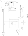
- the timer system 6 can comprise two analog timers consisting of two capacitors 4 (shown in figure 3 ). Taking advantage of the discharge time constant of the two capacitors 4, the two analog timers are implemented to allow the switch 11 to remain active for some minutes from the activation of the pressure element 13 and to delay the turning off of the switch 11 at the end of charging.
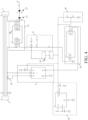
- the timer system 6 can consist solely of a capacitor C2 and a resistive network R3, R5, in particular a first resistor R3 and a second resistor R5 (shown in figure 4 ).
- the switch 11 can comprise a relay device 8.
- relay 8 as a switch 11 is shown in figure 3 .
- the meter device 1 works so as to read the current flowing between the input connector 3 (for example USB) and the output connector 7 (for example USB), disconnecting the device being charged when the current read falls below a certain threshold.
- This threshold is chosen to set the final battery charge level of the device, preventing the device from remaining connected to the power supply (i.e., to the adapter device 5) even at full charge.
- the meter device 1 reads the current flowing between the input connector 3 and the output connector 7 across the resistor 15 and pilots the relay 8 adapted to disconnect the device being charged when the current read falls below a certain threshold.
- the current is read/estimated by reading the voltage drop induced on the resistor 15 by the current flowing between the input connector 3 and the output connector 7.
- the relay 8 is in the open position and the device to be charged, connected to the output connector 7 via the charging element 9, is not charging, being disconnected from the adapter device 5.
- the two indicator lights 17 will indicate, for example with different colours, the state of the device: charging (connected to the adapter device 5) or not charging (disconnected from the adapter device 5).
- the current threshold at which the meter device 1 deactivates the relay 8, and thus disconnects the device to be charged is determined by the charge percentage of the rechargeable battery at which the charging is to be stopped. If the battery is to be disconnected when the device is fully charged, the threshold will be set to a slightly higher current than the current absorbed by the device while the battery is charged.
- the threshold can be set by the resistive divider 19 which can be fixed (fixed threshold) or variable (adjustable threshold). For example, a trimmer can be used as a resistive divider 19 to set the threshold. Taking advantage of the discharge time constant of the two capacitors 4, it is possible to keep the relay 8 active for a few minutes from the activation of the pressure element 13 and to delay the switching off of the relay 8 at the end of charging.
- the switch 11 can comprise a MOSFET 10.
- MOSFET metal-oxide-semiconductor
- FIG 4 An example application of MOSFET 10 as a switch 11 is shown in figure 4 . It should be noted that below, for reasons of convenience, repeating the explanation of the components of this figure having the same reference number as those in figure 3 will be avoided where possible.
- the current reader 2 is a voltage amplifier which amplifies the voltage drop on the resistor Rs 15.
- the amplified voltage value (which is linearly correlated with the current) is compared by the comparator 12 with a voltage value which corresponds to the desired current threshold (the voltage value is determined by a voltage divider 19 which uses the voltage stabilized by the regulator 14, for example at 4.4V.
- the output of the comparator 12 pilots the gate of the MOSFET 10 after being timed and filtered by the timer system 6.
- the timer system 6 consists of the network made up of the two resistors R3, R5 and the capacitor C2.
- timer system 6 consisting only of the three elements mentioned above (R3, R5 and C2) is capable of solving all four of the problems mentioned above in points 1-4, as explained below.
- the button 13 is connected between the positive voltage and the capacitor C2 which in turn is connected to the gate of the MOSFET 10.
- the button 13 When the button 13 is pressed, it charges C2 (almost instantly) which activates the MOSFET 10 which powers the device being charged.
- the capacitor C2 is then slowly discharged (about 3 minutes) through R5 and R3, giving the device time to activate the charging and absorb the current.
- the comparator 12 brings the output thereof to the high voltage value by recharging the capacitor which will continue to keep the MOSFET 10 active.
- the resistive network R3 and R5 prevents the capacitor C2 from recharging quickly (but with the characteristic time constant of the RC circuit) and as long as the integral over time of the current peaks which charge C2 through R3 remains lower than the discharge constant of C2 through R3 and R5 during the absence of the pulses and only through R5 during the pulses (as in this case R3 charges the capacitor), the capacitor C2 will discharge over time, deactivating the MOSFET 10 and thus disconnecting the device being charged.
- figure 3 shows a meter device 1 in which the switch 11 comprises a relay device 8 and the timer system 6 consists of two capacitors 4 (two timers) while figure 4 shows a meter device 1 in which the switch 11 comprises a MOSFET 10 and the timer system 6 consists of a single timer made up of a network of a capacitor C2 and two resistors R3, R5.
- the meter device 1 can have a switch 11 comprising a relay 8 as in figure 3 and a timer system 6 as in figure 4 .
- the meter device 1 can have a switch 11 comprising a MOSFET 10 as in figure 4 and a timer system 6 as in figure 3 .
- the switch 11 of the meter device 1 is activated by actuating a pressure element 13 and the method further comprises keeping the switch 11 activated for a predetermined time, in particular for a time between 1 and 5 minutes, from the actuation of the pressure element 13 regardless of the value of the current read.
- the method comprises restoring the charging state of the device to be charged if the power supply of the meter device 1 is stopped and restored, storing the state of the switch 11 for a predetermined time, in particular for a time between 1 and 5 minutes.
- the method comprises maintaining the output of the timer 6 as if the current read was below the current threshold if one or more current pulses, absorbed by the device to be charged, exceed the current threshold, when said device to be charged has reached the end of charging.
- the output of the timer 6 is maintained at a value below the current threshold by a current pulse filtering process.
- the method comprises maintaining the charging state of the device despite the measured current being less than the threshold, as long as the time interval for which it is less than the threshold is less than the value of the timer 6.
- the timer system 6 present in the current meter device 1 is restarted.
- the value of the threshold is always the same and is determined by the resistive divider 19.
- the pre-set time value is that determined by the timer system 6, for example between 1 and 5 minutes, advantageously three minutes.
- the method comprises at least one of the following steps:
- the method comprises disabling the ultra-fast charging function of the device to be charged during the charging step.
- the meter device 1 serves to avoid early wear of the rechargeable battery.
- the meter device 1 in addition to automatically disconnecting the device being charged when the battery is charged, the meter device 1 is also configured to disable the ultra-fast charging, typical of some devices to be charged, such as some mobile phones.
- the ultra-fast charging is turned off because it causes more battery wear than slow charging.
- the devices to be charged for example smartphones which use the standard USB 2.0 to recharge with powers beyond those allowed by the USB standard, use an additional pin of the standard 3.0 to be able to verify that the charger and cable are original and that they can therefore support powers much higher than those allowed by the normal cables (for example the Realme 7 Pro works at 10V 6.5A).
- the meter device 1 uses only the four pins of the standard USB 2.0 without connecting additional pins of the standard 3.0. Thereby, the device to be charged, even with the original adapter and cable, will not be able to read the "proprietary" pin for ultra-fast charging and consequently will not activate it.
- the current meter device 1 can comprise a microcontroller for digitally managing both the basic function of reading the current and activating/deactivating the switch 11 as described above, and communication with the device to be charged for more advanced functions.
- an application program (App) on the device to be charged e.g., on the smartphone
- different charging protocols can be implemented to allow the user to set the current being absorbed by the device.
- different charging protocols can be implemented to allow the user to set the current being absorbed by the device.
- the communication with the device to be charged can occur by means of the Bluetooth protocol which allows to monitor both the charge and the battery parameters (voltage, temperature, absorbed current) in real time, and to set the charging parameters on the meter device 1 to then use it on devices without Bluetooth or with the smartphone turned off.
- the device to be charged When the device to be charged is turned on and can communicate the charge state thereof in real time, it will be possible to set a maximum charge threshold at which the device being charged will be disconnected from the meter device 1 and thus from the adapter device 5 (charger). For example, by setting a 90% threshold, the device which reaches 90% battery charge will be disconnected from the charger. It is also possible to set a minimum charge threshold below which the device being charged will be reconnected to the charger (adapter device 5). For example, by setting a minimum threshold of 50% and a maximum of 60% it is possible to charge the device when the battery charge percentage reaches 50% and disconnect it from charging when the charge reaches 60%, thereby the battery will carry out charging and discharging cycles in an area away from harmful voltages (end of charge voltage and discharged battery voltage).
- the life of a battery is measured in charge cycles.
- the recharging cycle here refers to a discharge and a recharge of the entire capacity of the battery, not necessarily carried out in a single time. For example, in one day only half the charge of a notebook can be used, and then it is recharged completely. If the same thing is done the next day, only one recharge cycle is calculated, not two. Thereby, it may take several days for a cycle to complete. Charging a laptop up to 90% charge and only recharging it when the charge drops to 60%, the battery will cycle charging and discharging in an area away from harmful voltages. On the other hand, being able to avoid charging the battery while using the device, for example using only the mains, the battery would not lose valuable charging cycles and consequently it would increase the life thereof.
- a percentage threshold can be set even if the charging device is switched off (the smartphone and the meter device 1 cannot communicate directly).
- the meter device 1 After some learning recharges, in which the meter device 1 will create a correlation between the current flow and the charge percentage of a particular device, the meter device 1 will be able to understand, monitoring the charging current flow, the charge percentage of the battery and disconnect it accordingly to the desired percentage (clearly this feature can be exploited only in the step of saturation of the constant voltage current, therefore between 85% and 100% of the charge; in the charging step at a constant current, just as the current is constant, it is not possible to determine the charge percentage by reading the current flow).
- a threshold (always in the saturation step of the current) lower than 100% of the charge by specifying, for example through the application program, the moment in which to interrupt the current flow. For example, if a drone's battery is charged via USB and the charge is to be interrupted at 95%, as soon as that percentage is reached it will be set by the application on the smartphone that it is time to stop charging. The meter device 1 will store the information and the next time, by recalling the charging profile of the drone battery, it will stop charging at the desired charge percentage.
- a further function is represented by the Timer mode. Having a determined time to charge the mobile phone to a certain percentage, the meter device 1 can calculate and provide the best charging protocol to stress the battery as little as possible. For example, by setting through the application that two hours are available for charging the smartphone and it is to be charged up to 90% (and the current charge is 40%), the meter device 1 can calculate the current needed to provide the required charge (based on the capacity of the battery, the time it must take and the initial and final charge percentage) in the required time and can set the best charging protocol.
- a time at which the device to be charged (e.g., the smartphone) must be charged at a set percentage.
- a smartphone can be set to be 100% charged at 8 in the morning.
- the meter device 1 can calculate, based on the time available, the minimum current in order to be able to recharge it up to the desired percentage and the desired time.
- the meter device can decrease the charging current when the battery exceeds a "critical" temperature (pre-set or user modifiable), with the aim of stressing the battery as little as possible during the charging step and prolonging the life thereof as much as possible.
- a critical temperature pre-set or user modifiable
- the current meter device 1 described above can be applied in various technological sectors where devices equipped with lithium-ion batteries are present.
- the current meter device 1 can advantageously be used for charging particular household appliances, such as cordless vacuum cleaners, robot vacuum cleaners, or other home automation devices, and for charging electric vehicles such as electric scooters, electric bicycles and electric scooters.
Landscapes
- Engineering & Computer Science (AREA)
- Power Engineering (AREA)
- Physics & Mathematics (AREA)
- General Physics & Mathematics (AREA)
- Microelectronics & Electronic Packaging (AREA)
- Charge And Discharge Circuits For Batteries Or The Like (AREA)
Claims (11)
- Strommessvorrichtung (1), umfassend:eine Eingangsverbindervorrichtung (3) zum wirksamen Verbinden der Strommessvorrichtung (1) lösbar mit mindestens einer Adaptervorrichtung (5), wobei die Adaptervorrichtung (5) mit dem Stromversorgungsnetz verbindbar ist;eine Ausgangsverbindervorrichtung (7) zum wirksamen Verbinden der Strommessvorrichtung (1) lösbar mit mindestens einem Ladeelement (9), wobei das Ladeelement (9) wirksam mit mindestens einer zu ladenden Vorrichtung verbindbar ist, die mindestens eine wiederaufladbare Batterie aufweist;einen Stromabtaster (2) zum Abtasten des elektrischen Stroms, der zwischen der Eingangsverbindervorrichtung (3) und der Ausgangsverbindervorrichtung (7) fließt; undmindestens einen Schalter (11) zum wirksamen Verbinden der durch das Ladeelement (9) zu ladenden Vorrichtung mit der Strommessvorrichtung (1) und anschließend mit dem Adapter (5), wenn die Ladephase des zu ladenden Elements beginnt, und zum Trennen der zu ladenden Vorrichtung von der Strommessvorrichtung (1), wenn der elektrische Strom, der durch den Stromabtaster (2) abgetastet wird, geringer als eine Stromschwelle ist und die Ladephase abgeschlossen istdadurch gekennzeichnet, dassdie Strommessvorrichtung (1) ferner ein Zeitgebersystem (6) zur Anpassung der Aktivierung des Schalters (11), insbesondere zur Verzögerung oder Verhinderung der Aktivierung und/oder Deaktivierung des Schalters (11), umfasst, wobei das Zeitgebersystem (6) lediglich aus einem Kondensator (C2) und einem Widerstandsnetzwerk (R3, R5), insbesondere einem ersten Widerstand (R3) und einem zweiten Widerstand (R5), besteht, und wobei die Ausgabe des Zeitgebersystems (6) so aufrechterhalten wird, als würde der abgetastete Strom unterhalb der Stromschwelle liegen, wenn ein oder mehrere Stromimpulse, die von der zu ladenden Vorrichtung aufgenommen werden, die Stromschwelle überschreiten, wenn die zu ladende Vorrichtung das Ende der Aufladung erreicht hat.
- Strommessvorrichtung (1) nach Anspruch 1, die mindestens ein Druckelement (13) zum Aktivieren des Schalters (11) umfasst, wodurch die Ausgangsverbindervorrichtung (7) wirksam mit der Eingangsverbindervorrichtung (3) und anschließend mit der Adaptervorrichtung (5) verbunden wird.
- Strommessvorrichtung (1) nach Anspruch 1 oder 2, die einen Widerstand Rs (15) umfasst, der zwischen der Eingangsverbindervorrichtung (3) und der Ausgangsverbindervorrichtung (7) angeordnet ist, wobei der Strommesser konfiguriert ist, den elektrischen Strom, der zwischen der Eingangsverbindervorrichtung (3) und der Ausgangsverbindervorrichtung (7) fließt, durch Abtasten des an dem Widerstand Rs (15) induzierten Spannungsabfalls zu messen.
- Strommessvorrichtung (1) nach einem der vorhergehenden Ansprüche, die mindestens ein Indikatorelement (17) zum Senden eines ersten Lichtsignals, wenn die Strommessvorrichtung (1) wirksam mit der Adaptervorrichtung (5) verbunden ist, und zum Senden eines zweiten Lichtsignals, wenn die Strommessvorrichtung (1) wirksam von der Adaptervorrichtung (5) getrennt ist, umfasst.
- Strommessvorrichtung (1) nach einem der vorhergehenden Ansprüche, die mindestens ein Spannungsreferenz-Bestimmungselement, insbesondere ein Widerstandsteilerelement (19), zum Bestimmen der Stromschwelle, bei der die Strommessvorrichtung (1) die Ausgangsvorrichtung (7) über den Schalter (11) wirksam von der Eingangsvorrichtung (3) trennt, umfasst.
- Strommessvorrichtung (1) nach einem der vorhergehenden Ansprüche, wobei der Schalter (11) Folgendes umfassta. eine Relaisvorrichtung (8); und/oderb. einen MOSFET (10).
- Strommessvorrichtung (1) nach einem der vorhergehenden Ansprüche, die ferner einen Mikrocontroller umfasst.
- Verfahren zum Beschränken der Beanspruchung mindestens einer wiederaufladbaren Batterie, die mit einer zu ladenden Vorrichtung verbunden ist, umfassend:lösbares Verbinden einer Strommessvorrichtung (1) zwischen einer Adaptervorrichtung (5) und einem Ladeelement (9), wobei die Strommessvorrichtung (1) einen Eingangsverbinder (3), der mit der Adaptervorrichtung (5) verbindbar ist, und einen Ausgangsverbinder (7), der mit dem Ladeelement (9) verbindbar ist, umfasst und die Adaptervorrichtung (5) mit dem Stromversorgungsnetz verbindbar ist und das Ladeelement (9) wirksam mit der zu ladenden Vorrichtung verbindbar ist,Abtasten des elektrischen Stroms, der zwischen der Eingangsverbindervorrichtung (3) und der Ausgangsverbindervorrichtung (7) fließt;Aktivieren eines Schalters (11) der Strommessvorrichtung (1), um die zu ladende Vorrichtung über das Ladeelement (9) wirksam mit der Strommessvorrichtung (1) und anschließend mit dem Adapter (5) zu verbinden, wenn die Ladephase des zu ladenden Elements beginnt; undDeaktivieren des Schalters (11), um die zu ladende Vorrichtung von der Strommessvorrichtung (1) zu trennen, wenn der elektrische Strom, der durch den Stromabtaster (2) abgetastet wird, geringer als die Stromschwelle ist und die Ladephase abgeschlossen ist,gekennzeichnet durchAufrechterhalten der Ausgabe eines Zeitgebersystems (6), das in der Strommessvorrichtung (1) vorhanden ist, so, als würde der abgetastete Strom unter der Stromschwelle liegen, wenn ein oder mehrere Stromimpulse, die von der zu ladenden Vorrichtung aufgenommen werden, die Stromschwelle überschreiten, wenn die zu ladende Vorrichtung das Ende der Aufladung erreicht hat.
- Verfahren nach Anspruch 8, wobei das Aktivieren des Schalters (11) der Strommessvorrichtung (1) durch Betätigen eines Druckelements (13) erfolgt und das Verfahren ferner Folgendes umfasst:a. Aktiviertlassen des Schalters (11) für eine vorbestimmte Zeit, insbesondere für eine Zeit zwischen 1 und 5 Minuten, ab der Betätigung des Druckelements (13) unabhängig von dem Wert des abgetasteten Stroms; und/oderb. Wiederherstellen des Ladezustands der zu ladenden Vorrichtung, wenn die Stromversorgung der Strommessvorrichtung (1) unterbrochen und wiederhergestellt wird, wobei der Zustand des Schalters (11) für eine vorbestimmte Zeit, insbesondere für eine Zeit zwischen 1 und 5 Minuten, gespeichert wird.
- Verfahren nach einem der Ansprüche 8 bis 9, das ferner ein Neustarten eines Zeitgebersystems (6), das in der Strommessvorrichtung (1) vorhanden ist, in Abhängigkeit von dem abgetasteten elektrischen Strom, wenn der von der Vorrichtung, die geladen wird, aufgenommene Strom wiederhergestellt ist, umfasst, immer dann, wenn der abgetastete elektrische Strom einen vorgegebenen Schwellenwert für ein vorbestimmtes Zeitintervall überschreitet.
- Verfahren nach einem der Ansprüche 8 bis 10, das ferner mindestens einen der folgenden Schritte umfasst:Versorgen der zu ladenden Vorrichtung direkt über das Netz ohne gleichzeitiges Versorgen der wiederaufladbaren Batterie, die mit der zu ladenden Vorrichtung verbunden ist;Variieren des Werts der Aufladung der wiederaufladbaren Batterie, die mit der zu ladenden Vorrichtung verbunden ist, zwischen einem maximalen Ladewert und einem minimalen Entladewert in zyklischer und automatischer Weise;Einstellen einer prozentualen Stromschwelle, bei der die zu ladende Vorrichtung getrennt werden soll, selbst dann, wenn die zu ladende Vorrichtung ausgeschaltet ist;Messen des Werts der Temperatur der wiederaufladbaren Batterie, die mit der zu ladenden Vorrichtung verbunden ist, und Anpassen des Werts des Ladestroms in Abhängigkeit von dem Temperaturwert; undDeaktivieren einer Funktion für ultraschnelles Laden der Vorrichtung, die während des Ladeschritts geladen werden soll.
Applications Claiming Priority (2)
| Application Number | Priority Date | Filing Date | Title |
|---|---|---|---|
| IT202000022249 | 2020-09-22 | ||
| PCT/IB2021/058486 WO2022064334A1 (en) | 2020-09-22 | 2021-09-17 | Current measurement device for mobile rechargeable devices |
Publications (3)
| Publication Number | Publication Date |
|---|---|
| EP4232830A1 EP4232830A1 (de) | 2023-08-30 |
| EP4232830B1 true EP4232830B1 (de) | 2024-10-23 |
| EP4232830C0 EP4232830C0 (de) | 2024-10-23 |
Family
ID=73793589
Family Applications (1)
| Application Number | Title | Priority Date | Filing Date |
|---|---|---|---|
| EP21785997.4A Active EP4232830B1 (de) | 2020-09-22 | 2021-09-17 | Strommessvorrichtung für mobile wiederaufladbare geräte |
Country Status (3)
| Country | Link |
|---|---|
| US (1) | US20230408589A1 (de) |
| EP (1) | EP4232830B1 (de) |
| WO (1) | WO2022064334A1 (de) |
Family Cites Families (6)
| Publication number | Priority date | Publication date | Assignee | Title |
|---|---|---|---|---|
| US7910834B2 (en) * | 2008-05-27 | 2011-03-22 | Voltstar Technologies, Inc. | Energy saving cable assemblies |
| US10992142B2 (en) * | 2010-07-26 | 2021-04-27 | Robert M. Schwartz | Current sensing circuit disconnect device and method |
| US9362764B2 (en) * | 2012-01-23 | 2016-06-07 | Tsuga Engineering Llc | Portable rechargeable power supply |
| EP2950420B1 (de) * | 2013-01-25 | 2019-07-24 | Hitachi Automotive Systems, Ltd. | Zellsteuerung und zellüberwachungsvorrichtung |
| US10061280B2 (en) * | 2014-07-22 | 2018-08-28 | Advanced Magnetic Solutions Limited | Controlled power adapter and cable |
| CN105244981B (zh) * | 2015-11-20 | 2017-12-26 | 深圳市祝你快乐科技有限公司 | 一种能自动断电的节能充电器 |
-
2021
- 2021-09-17 EP EP21785997.4A patent/EP4232830B1/de active Active
- 2021-09-17 WO PCT/IB2021/058486 patent/WO2022064334A1/en not_active Ceased
- 2021-09-17 US US18/027,714 patent/US20230408589A1/en active Pending
Also Published As
| Publication number | Publication date |
|---|---|
| WO2022064334A1 (en) | 2022-03-31 |
| US20230408589A1 (en) | 2023-12-21 |
| EP4232830A1 (de) | 2023-08-30 |
| EP4232830C0 (de) | 2024-10-23 |
Similar Documents
| Publication | Publication Date | Title |
|---|---|---|
| JP7198293B2 (ja) | 電池充電器 | |
| US8368252B2 (en) | High- and low-power power supply with standby power saving features | |
| US20130093381A1 (en) | Energy saving cable assembly | |
| EP3007306A1 (de) | Ladeverfahren für eine elektronische zigarette und schachtel für elektronische zigaretten | |
| US20140360512A1 (en) | Charging method of electronic cigarettes and electronic cigarette box | |
| US20100019583A1 (en) | Load condition controlled power module | |
| WO2012075165A2 (en) | Load condition controlled inline power controller | |
| CN102437625A (zh) | 充电器 | |
| CA2714355C (en) | Load condition controlled power circuit | |
| WO2006073630A2 (en) | Battery pack, system, and method for waking up a charge control circuit of a mobile communication device | |
| WO2015110584A1 (en) | Battery charger | |
| EP4232830B1 (de) | Strommessvorrichtung für mobile wiederaufladbare geräte | |
| WO2017117400A1 (en) | Modular battery system | |
| CN206908345U (zh) | 一种数控移动电源 | |
| JP3249152U (ja) | 充電式モバイルデバイス用電流計デバイス | |
| CN209200742U (zh) | 插座 | |
| CA3092712C (en) | Charge state control system and device | |
| CN206790169U (zh) | 直流充电器自动断电电路 | |
| KR20150056739A (ko) | 2차 전지를 구비한 충전장치 | |
| KR101807761B1 (ko) | 배터리 충전 감시 장치 | |
| CN112087006A (zh) | 一种电池包、充电系统及放电系统 | |
| CN112087009A (zh) | 一种电池包 | |
| US20210066942A1 (en) | Charge state control system and device | |
| CA2419497C (en) | Circuit and method of operation for an adaptive charge rate power supply | |
| CN202535096U (zh) | 多功能智能电池充电、放电器 |
Legal Events
| Date | Code | Title | Description |
|---|---|---|---|
| STAA | Information on the status of an ep patent application or granted ep patent |
Free format text: STATUS: UNKNOWN |
|
| STAA | Information on the status of an ep patent application or granted ep patent |
Free format text: STATUS: THE INTERNATIONAL PUBLICATION HAS BEEN MADE |
|
| PUAI | Public reference made under article 153(3) epc to a published international application that has entered the european phase |
Free format text: ORIGINAL CODE: 0009012 |
|
| STAA | Information on the status of an ep patent application or granted ep patent |
Free format text: STATUS: REQUEST FOR EXAMINATION WAS MADE |
|
| 17P | Request for examination filed |
Effective date: 20230414 |
|
| AK | Designated contracting states |
Kind code of ref document: A1 Designated state(s): AL AT BE BG CH CY CZ DE DK EE ES FI FR GB GR HR HU IE IS IT LI LT LU LV MC MK MT NL NO PL PT RO RS SE SI SK SM TR |
|
| DAV | Request for validation of the european patent (deleted) | ||
| DAX | Request for extension of the european patent (deleted) | ||
| GRAP | Despatch of communication of intention to grant a patent |
Free format text: ORIGINAL CODE: EPIDOSNIGR1 |
|
| STAA | Information on the status of an ep patent application or granted ep patent |
Free format text: STATUS: GRANT OF PATENT IS INTENDED |
|
| INTG | Intention to grant announced |
Effective date: 20240412 |
|
| GRAS | Grant fee paid |
Free format text: ORIGINAL CODE: EPIDOSNIGR3 |
|
| GRAA | (expected) grant |
Free format text: ORIGINAL CODE: 0009210 |
|
| STAA | Information on the status of an ep patent application or granted ep patent |
Free format text: STATUS: THE PATENT HAS BEEN GRANTED |
|
| AK | Designated contracting states |
Kind code of ref document: B1 Designated state(s): AL AT BE BG CH CY CZ DE DK EE ES FI FR GB GR HR HU IE IS IT LI LT LU LV MC MK MT NL NO PL PT RO RS SE SI SK SM TR |
|
| REG | Reference to a national code |
Ref country code: GB Ref legal event code: FG4D |
|
| REG | Reference to a national code |
Ref country code: CH Ref legal event code: EP |
|
| REG | Reference to a national code |
Ref country code: DE Ref legal event code: R096 Ref document number: 602021020735 Country of ref document: DE |
|
| REG | Reference to a national code |
Ref country code: IE Ref legal event code: FG4D |
|
| U01 | Request for unitary effect filed |
Effective date: 20241030 |
|
| U07 | Unitary effect registered |
Designated state(s): AT BE BG DE DK EE FI FR IT LT LU LV MT NL PT RO SE SI Effective date: 20241112 |
|
| U1N | Appointed representative for the unitary patent procedure changed after the registration of the unitary effect |
Representative=s name: PACE NAPOLEONE, MARIA; IT |
|
| PG25 | Lapsed in a contracting state [announced via postgrant information from national office to epo] |
Ref country code: IS Free format text: LAPSE BECAUSE OF FAILURE TO SUBMIT A TRANSLATION OF THE DESCRIPTION OR TO PAY THE FEE WITHIN THE PRESCRIBED TIME-LIMIT Effective date: 20250223 Ref country code: HR Free format text: LAPSE BECAUSE OF FAILURE TO SUBMIT A TRANSLATION OF THE DESCRIPTION OR TO PAY THE FEE WITHIN THE PRESCRIBED TIME-LIMIT Effective date: 20241023 |
|
| PG25 | Lapsed in a contracting state [announced via postgrant information from national office to epo] |
Ref country code: ES Free format text: LAPSE BECAUSE OF FAILURE TO SUBMIT A TRANSLATION OF THE DESCRIPTION OR TO PAY THE FEE WITHIN THE PRESCRIBED TIME-LIMIT Effective date: 20241023 |
|
| PG25 | Lapsed in a contracting state [announced via postgrant information from national office to epo] |
Ref country code: NO Free format text: LAPSE BECAUSE OF FAILURE TO SUBMIT A TRANSLATION OF THE DESCRIPTION OR TO PAY THE FEE WITHIN THE PRESCRIBED TIME-LIMIT Effective date: 20250123 |
|
| PG25 | Lapsed in a contracting state [announced via postgrant information from national office to epo] |
Ref country code: GR Free format text: LAPSE BECAUSE OF FAILURE TO SUBMIT A TRANSLATION OF THE DESCRIPTION OR TO PAY THE FEE WITHIN THE PRESCRIBED TIME-LIMIT Effective date: 20250124 |
|
| PG25 | Lapsed in a contracting state [announced via postgrant information from national office to epo] |
Ref country code: PL Free format text: LAPSE BECAUSE OF FAILURE TO SUBMIT A TRANSLATION OF THE DESCRIPTION OR TO PAY THE FEE WITHIN THE PRESCRIBED TIME-LIMIT Effective date: 20241023 |
|
| PG25 | Lapsed in a contracting state [announced via postgrant information from national office to epo] |
Ref country code: RS Free format text: LAPSE BECAUSE OF FAILURE TO SUBMIT A TRANSLATION OF THE DESCRIPTION OR TO PAY THE FEE WITHIN THE PRESCRIBED TIME-LIMIT Effective date: 20250123 |
|
| PG25 | Lapsed in a contracting state [announced via postgrant information from national office to epo] |
Ref country code: SM Free format text: LAPSE BECAUSE OF FAILURE TO SUBMIT A TRANSLATION OF THE DESCRIPTION OR TO PAY THE FEE WITHIN THE PRESCRIBED TIME-LIMIT Effective date: 20241023 |
|
| PG25 | Lapsed in a contracting state [announced via postgrant information from national office to epo] |
Ref country code: SK Free format text: LAPSE BECAUSE OF FAILURE TO SUBMIT A TRANSLATION OF THE DESCRIPTION OR TO PAY THE FEE WITHIN THE PRESCRIBED TIME-LIMIT Effective date: 20241023 |
|
| PG25 | Lapsed in a contracting state [announced via postgrant information from national office to epo] |
Ref country code: CZ Free format text: LAPSE BECAUSE OF FAILURE TO SUBMIT A TRANSLATION OF THE DESCRIPTION OR TO PAY THE FEE WITHIN THE PRESCRIBED TIME-LIMIT Effective date: 20241023 |
|
| PLBE | No opposition filed within time limit |
Free format text: ORIGINAL CODE: 0009261 |
|
| STAA | Information on the status of an ep patent application or granted ep patent |
Free format text: STATUS: NO OPPOSITION FILED WITHIN TIME LIMIT |
|
| 26N | No opposition filed |
Effective date: 20250724 |