EP4232829B1 - Vorrichtungen, systeme und verfahren zur messung der produktion radioaktiver isotope in masse - Google Patents
Vorrichtungen, systeme und verfahren zur messung der produktion radioaktiver isotope in masse Download PDFInfo
- Publication number
- EP4232829B1 EP4232829B1 EP21807485.4A EP21807485A EP4232829B1 EP 4232829 B1 EP4232829 B1 EP 4232829B1 EP 21807485 A EP21807485 A EP 21807485A EP 4232829 B1 EP4232829 B1 EP 4232829B1
- Authority
- EP
- European Patent Office
- Prior art keywords
- arm
- radionuclides
- central rod
- source cage
- orientation
- Prior art date
- Legal status (The legal status is an assumption and is not a legal conclusion. Google has not performed a legal analysis and makes no representation as to the accuracy of the status listed.)
- Active
Links
Images




Classifications
-
- G—PHYSICS
- G01—MEASURING; TESTING
- G01T—MEASUREMENT OF NUCLEAR OR X-RADIATION
- G01T7/00—Details of radiation-measuring instruments
- G01T7/02—Collecting means for receiving or storing samples to be investigated and possibly directly transporting the samples to the measuring arrangement; particularly for investigating radioactive fluids
-
- G—PHYSICS
- G01—MEASURING; TESTING
- G01T—MEASUREMENT OF NUCLEAR OR X-RADIATION
- G01T1/00—Measuring X-radiation, gamma radiation, corpuscular radiation, or cosmic radiation
- G01T1/16—Measuring radiation intensity
- G01T1/167—Measuring radioactive content of objects, e.g. contamination
-
- G—PHYSICS
- G01—MEASURING; TESTING
- G01T—MEASUREMENT OF NUCLEAR OR X-RADIATION
- G01T1/00—Measuring X-radiation, gamma radiation, corpuscular radiation, or cosmic radiation
- G01T1/16—Measuring radiation intensity
- G01T1/185—Measuring radiation intensity with ionisation chamber arrangements
-
- G—PHYSICS
- G01—MEASURING; TESTING
- G01T—MEASUREMENT OF NUCLEAR OR X-RADIATION
- G01T7/00—Details of radiation-measuring instruments
- G01T7/005—Details of radiation-measuring instruments calibration techniques
Definitions
- the present disclosure is generally related to nuclear power generation and, more particularly, is directed to an improved device configured to measure radioactive isotope production in bulk.
- GB Patent Application No. 884 349 A discloses a radioactivity measuring apparatus, comprising a storage support having means to hold a plurality of samples disposed in an arcuate array-about a centre, a radiation detector mounted at the centre of the arc on which the samples are disposed, and means for transferring the samples one at a time from the support to the detector for measurement and back, the background radiation received by the detector from stored samples remaining substantially constant.
- 3 141 977 discloses a radioactive sample processing apparatus comprising storage for delivering radioactive samples in a predetermined fixed order in sequence to an access point; a detector adapted to measure the disintegration rate of radioactive samples, disposed above and in horizontally displaced relationship with respect to the storage; transport means adapted to individually withdraw one of the samples from the fixed order and to transport it both vertically and horizontally from the access point to the detector and back to the fixed order at the access point prior to transporting the next sequential sample.
- a device configured to measure radioactivity emitted by a plurality of radionuclides according to claim 6, and a method of measuring radioactivity emitted by a plurality of radionuclides according to claim 1 is disclosed.
- Radionuclides e.g. Cobalt 60, Molybdenum-99, Cesium-137, lodirie-1 31, Strontium-90, Technetium-99, Americium-241, and/or atomic variations of Plutonium, Uranium, Radium, Radon, Thorium, Tritium
- Radionuclides possess a wide-variety of useful applications.
- radionuclides can be used to improve the safety of medical devices, assist in the treatment of cancer, and reduce pathogens in foods and other products.
- radioactive isotopes emit harmful gamma rays that can be carcinogenic to humans depending on the degree of exposure. This can complicate the production, processing, and handling of radionuclides. In spite of these inherent risks, industry continues to produce and ship large quantities of radionuclides, expanding their many uses in an attempt to realize their full potential.
- radionuclides configured as capsules
- the disclosed inventions can be implemented or easily modified-to measure the radioactivity emitted by radionuclides in any number of geometric configurations, not necessarily capsulated radionuclides.
- capsule shall not be construed as a geometrical limitation of the radionuclides.
- FIG. 1 a perspective view of a source cage 100 of a device configured to measure radioactivity emitted by a plurality of radionuclides 106 in bulk is depicted in accordance with at least one non-limiting aspect of the present disclosure.
- the source cage 100 of FIG. 1 is configured to safely store and ship a large shipment of radionuclides.
- the source cage 100 of FIG. 1 can be used to ship 48 radionuclide capsules.
- the capacity of the source cage 100 of FIG. 1 can be easily scaled or otherwise reconfigured to accommodate more or less radionuclides, in any desired form, as long as the storage geometry remains three-hundred-and-sixty-degree symmetric with respect to its centerline.
- the source cage 100 of FIG. 1 can include one or more outer rings 102 that define a volume 104.
- the outer rings 102 are circular and thus, the volume 104 is cylindrical.
- the present disclosure contemplates other non-limiting aspects wherein the source cage 100 can include any number of geometric structures and volumes, as long as the geometric structures and volumes remain three-hundred-and-sixty-degree symmetric with respect to their centerlines.
- the outer rings 104 of the source cage 100 of FIG. 1 can further include a plurality of holes 105, wherein each hole 105 of the plurality of holes 105 can be configured to receive a radionuclide 106 of the plurality of radionuclides 106.
- the present disclosure contemplates other means of receiving and securing the radionuclides 106.
- the source cage 100 of FIG. 1 can additionally and/or alternatively include gripping components, cradles, and/or other structural elements to either assist or replace the plurality of holes 105 depicted in the non-limiting embodiment of FIG. 1 .
- These structural components most simply secure the radionuclides 106 at a predetermined position, i.e., centerline, of the source cage 100.
- the source cage 100 of FIG. 1 can include a three-hundred-and-sixty degree form, such that each radionuclide is equidistant from a center point of a circular plane defined by an upper surface of the outer ring 102.
- the source cage 100 of FIG. 100 can include an inner diameter D1.
- the plurality of holes 105 can be defined in the outer ring 106 such that, when installed, each radionuclide 106 of the plurality of radionuclides 106 is positioned the same distance away from the center point of the cylindrical volume 104, or in other words, the center point of the inner diameter D1.
- the radionuclides 106 can be configured to be the same distance from any reference point on a source cage 100 of any other geometrical configuration. It shall be appreciated that the cylindrical source cage 100 of FIG. 1 is merely depicted for ease of illustration.
- the radionuclides 106 can be structured as elongated rods.
- the source cage 100 can include three outer rings 102 supported by one or more standoff rods 109 configured to orient and support the outer rings 102 such that the plurality of holes 105 of a first outer ring 102 aligns with the plurality of holes 105 of a second outer ring 102.
- Each of the plurality of holes 105 can include a circular bore configured to accommodate the circular cross-section of each of the radionuclides 106. This allows for the rod-shaped radionuclides 106 to be properly inserted into the tioles 105 and supported within each outer ring 102 of the source cage 100 of FIG. 1 .
- the present disclosure contemplates other non-limiting aspects, wherein the radionuclides 106 include varying shapes and sizes. As previously discussed, the present disclosure contemplates other non-limiting aspects, wherein the source cage 106 can include components of varying shapes and configurations to effectively accommodate and secure any shape of radionuclide 106. Once the radionuclides 106 are inserted into the holes 105, the source cage 100 can be submerged in water for testing and/or processing.
- the source cage 100 further includes an orientation feature 107, such as a notch, a slot, an opening, and/or the like.
- the orientation feature 107 comprises an orientation notch configured to receive an orientation pin 209 ( FIG. 2 ) of a frame 200 ( FIG. 2 ) configured to be coupled to the source cage 100.
- the orientation notch 107 is specifically positioned such that a gamma detector 207 ( FIG. 2 ) coupled to the central rod 208 ( FIG. 2 ) of the frame 200 ( FIG. 2 ) is positioned in a predetermined location within the cylindrical volume 104.
- the present disclosure contemplates other non-limiting aspects in which the source cage 100 can include several orientation notches 107, or any combination of other geometric features 107, which can allow a technician to position the gamma detector 207 ( FIG. 2 ) coupled to the central rod 208 ( FIG. 2 ) of the frame 200 ( FIG. 2 ) in a variety of predetermined positions within the cylindrical volume 104. This can allow the technician to reorient and reposition the gamma detector 207 ( FIG. 2 ) to accommodate for margins of error, or enhance measurement accuracy.
- the source cage can further include a pre-existing geometrical feature that the gamma detector 207 ( FIG.
- the source cage can further include a centerpiece that protrudes from the bottom of the source cage through the center of cylindrical volume 104.
- a gamma detector- such as a self-powered detector 302 ( FIG. 3 )-can be strategically positioned about the centerpiece, as desired, instead of a gamma detector-such as an ion chamber detector 207 ( FIG. 2 ) -being suspended within the cylindrical volume 104 via a central rod 208 ( FIG. 2 ) of a frame 200 ( FIG. 2 ).
- the frame 200 can include a central rod 208, as well as a first arm 201, a second arm 202, a third arm 203, and a fourth arm 204.
- the arms 201, 202, 203, 204 can be specifically configured to couple to the outer ring 102 of the source cage 100.
- the first arm 201 and the fourth arm 204 can collectively define a frame diameter D2 that is larger than the inner diameter D1 ( FIG. 1 ) of the source cage 100 ( FIG. 1 ). Accordingly, the first arm 201 and fourth arm 204 can support the frame 200 such that the central rod 208 is suspended within the cylindrical volume 104 ( FIG. 1 ) of the source cage 100 ( FIG. 1 ).
- the frame 200 can include any number of arms 201, 202, 203, 204 in varying configurations to achieve the same result.
- the frame 200 can include a single arm 201 configured to be clamped to the outer ring 102 ( FIG. 1 ) and suspend the central rod 208 within the cylindrical volume 104 ( FIG. 1 ) of the source cage 100 ( FIG. 1 ).
- the arms 201, 202, 203, 204 of the frame 200 can be configured to move relative to the outer ring 102 ( FIG.1 ) of the source cage 100 ( FIG.1 ) once they are installed.
- the arms 201, 202, 203, 204 can include additional structural components such as hinges, rollers, tracks, and/or the like which can be used to angle the arms 201, 202, 203, 204 relative to a plane defined by a top surface of the outer ring 102.
- the frame 200 and, more specifically, the arms 201, 202, 203, 204 can be articulated and thus, capable of moving the central rod 208 between a number of predetermined locations within the cylindrical volume 104 ( FIG.1 ).
- the central rod 208 of the frame 200 can be configured to suspend a gamma detector 207 within the cylindrical volume 104 ( FIG.1 ) of the source cage 100 ( FIG.1 ), wherein the gamma detector 107 will be exposed to gamma rays emitted by the plurality of radionuclides 106 ( FIG.1 ).
- the gamma detector 207 can be integral to-and positioned at an end of— the central rod 208.
- the central rod 208 can be further configured to include and/or house a signal cable 206, such that signals can be routed from the gamma detector 207 to a remotely located data acquisition unit.
- FIG.2 includes a signal cable 206 to rout signals from the gamma detector 207 to a remotely located data acquisition unit, other non-limiting aspects include gamma detectors 207 that can be configured for wireless communication.
- the central rod 208 of FIG.2 can be further configured to be coupled to an external gamma detector 207.
- the gamma detector 207 can include a farmer ion chamber installed on a sleeve configured to be installed over and around an end of the central rod 208.
- the sleeve can include a housing specifically configured to position the gamma detector 207 at a desired orientation relative to the central rod 208, such as the center line.
- the gamma detector 207 can further include a self-powered detector (e.g. platinum).
- the self-powered detector can be configured to be wound around an end of the central rod 208, forming a tight, spiral configuration, as depicted in FIG.3 .
- FIG.2 depicts a gamma detector 207 coupled to the end of the central rod 208
- any number of detectors can be coupled to the central rod 208 depending on user preference and/or intended application of the frame 200.
- the central rod 208 is configured such that a technician can couple any number or spectroscopes or non-invasive test equipment to it in a similar manner to the gamma detector 207. Accordingly, a technician can utilize the frame 200 of FIG.2 to perform any number of tests on a bulk shipment of radionuclides, thereby ensuring compliance with any number of governmental regulations and/or contractual obligations.
- the central rod 208 can be simultaneously configured to accommodate any number of gamma detectors 207, spectroscopes, and/or non-invasive test equipment. This can provide the frame 200 with a degree of modularity and flexibility of use, enabling a technician to perform any number of tests on a bulk shipment of radionuclides using the same frame 200 by simple swapping out the gamma detector for another spectroscope and/or piece of test equipment.
- the gamma detector 300 can include a self-powered detector 302 positioned around an inner tube 304 and an outer tube 306 positioned.
- the central rod 208 FIG.2
- the gamma detector 300 can include a separate tube, which serves as a sleeve configured to be coupled to the central rod 208 ( FIG.2 ).
- the outer tube 306, self-powered detector 302, and the inner tube 304 can be specifically configured to ensure that the self-powered detector 302 does not move relative to the central rode 208 ( FIG.2 ), as the orientation of the self-powered detector 302 relative to the plurality of radionuclides 106 ( FIG.1 ) can affect the measurement.
- the self-powered detector 302 can be used to measure an amount of gamma rays emitted by the plurality of radionuclides 106 ( FIG.1 ).
- the self-powered detector 302 can measure an amount of gamma rays because an electrical current is induced throughout the spiral configuration when the self-powered detector 302 is in the proximity of a radionuclide.
- the electrical current induced within the self-powered detector 302 can be measured in a number of different ways.
- the sensitivity of the self-powered detector 302 can be calculated via testing, and will vary depending on the amount of electrical current generated given the length of the self-powered detector 302 based on a known quantity of gamma ray exposure.
- the calculated sensitivity can be used to measure the collective gamma rays emitted by the plurality of radionuclides 106 ( FIG.1 ).
- the self-powered detector 302 of FIG.3 is configured to measure gamma rays, according to other aspects of the present disclosure, the self-powered detector 302 can be configured to measure other types of radiation.
- the gamma detector 300 of FIG.3 can include a self-powered detector 302 configured to measure gamma rays, in still other non-limiting aspects contemplate the gamma detector 300 can include any number of radiation detectors (e.g. a farmer ion chamber and/or the like).
- FIG.4 a perspective view of a device 400 configured to measure radioactivity emitted by a plurality of radionuclides 404 in bulk is depicted in accordance with at least one non-limiting aspect of the present disclosure.
- the device 40 can include a source cage 402 and a frame 408 similar to the source cage 100 and frame 200 depicted in FIGS.1 and 2 , respectively.
- FIG.4 illustrates how previously disclosed elements can be integrated into a device 400 configured to measure radioactivity emitted by a plurality of radionuclides 41 in bulk.
- a technician might use the device 400 of FIG.4 to store and ship a large number of radionuclides 404-a contractual deliverable-to a receiving customer.
- a technician might use the device 400 of FIG.4 to store and ship a large number of radionuclides 404 internally.
- the device 400 of FIG.4 can be used to efficiently ensure that a shipment of radionuclides 404-and more specifically, the radioactivity emitted by the radionuclides 404-complies with governmental regulations and/or contractual obligations.
- the orientation and/or the position of a gamma detector 414 relative to the plurality of radionuclides 404 can affect the integrity of a measurement. Accordingly, the gamma detector 414 can be optimally positioned within the cylindrical volume defined by the outer ring 406 and therefore, can receive the desired exposure to radioactivity emitted by the plurality of radionuclides 404.
- the arms 410 of the frame 408 are configured to rest on the outer ring 406 of the source cage 402. As such, the central rod 412 can suspend a gamma detector 414 within the cylindrical volume defined by the outer ring 406.
- the position of the gamma detector 414 within the cylindrical volume defined by the outer ring 406 can be adjusted by modifying a length of the central rod 412.
- the present disclosure contemplates non-limiting aspects wherein the central rod 412 can be telescopically configured.
- an orientation notch 422 of the source cage 402 can be configured to receive and secure an orientation pin 420 of the frame 408.
- the gamma detector 414 can be positioned in a predetermined location relative to the cylindrical volume defined by the outer ring 406 when the orientation pin 420 of the frame 408 is received by the orientation notch 422 of the source cage 402. As such, a technician does not need to waste time arranging the frame 408 and the source cage 402 to properly position the gamma detector 414 within the cylindrical volume. Instead, the technician can align the orientation pin 420 with the orientation notch 422.
- the frame 408 can be secured relative to the source cage 402 when the orientation pin 420 is received by the orientation notch 422, thereby ensuring the desired configuration will not be perturbed.
- the non-limiting aspect of FIG. 4 can include an orientation pin 420 and an orientation notch 422
- other non-limiting aspects of the present disclosure include any number of mechanical components and/or features configured to properly orient and secure the frame 408 to the source cage 402. For example, a variety of mating geometries, interacting components, visual markings, and/or combinations thereof can be implemented, depending on the intended application and/or specific technician preference.
- the source cage 402 of FIG. 4 can include more than one orientation notch 422, wherein each orientation notch 422, when engaged with the orientation pin 420 of the frame 408, will orient the gamma detector 414 in a particular predetermined position of a plurality of predetermined positions within the volume defined by the outer ring 406. This can provide a technician with the flexibility to adjust the position of the gamma detector 414 as desired, while retaining the aforementioned ease-of-use and efficiencies.
- the device 400 can be calibrated and/or reconfigured to optimize the integrity of a measurement, as desired.
- a technician can utilize the frame 408 and source cage 402 of the device to initially orient the gamma detector 414 within the internal volume defined by the outer ring 406. Once the gamma detector 414 is initially positioned, the technician can install a single radionuclide 414 of a plurality of radionuclides 414 into the source cage 402 and take a baseline measurement of the radioactivity emitted by the single radionuclide 414.
- the technician may proceed to install each radionuclide 414 of the plurality of radionuclides 414 into the source cage 402 and take a collective measurement of radioactivity emitted by the plurality of radionuclides 414.
- the technician can then compare the collective measurement to the baseline measurement and determine a correction factor based, at least in part, on the comparison. For example, if the baseline measurement of the single radionuclide 414 was one Curie, the technician might expect that the collective measurement would be 48 Curies. However, if the collective measurement significantly diverges from the what would be expected based on the baseline measurement, the technician might determine a correction factor, which can account for an acceptable margin of error.
- the technician might decide to reposition the gamma detector 414 within the cylindrical volume based, at least in part, on the determined correction factor.
- the aforementioned structural features of the device 400 of FIG. 4 can assist the technician in easily making these adjustments and therefore, facilitate a more efficient acquisition of accurate data associated with the anticipated shipment.
- the device 400 can be capable of enhancing the efficiency of radioactivity measurements due to its symmetrical geometry.
- the source cage 402 includes a three-hundred and sixty degree geometry that is symmetric relative to a radial centerline of the plane defined by the outer ring 406.
- the device 400 can achieve a detection efficiency, which can be defined as the calibrated efficiency ("E") multiplied by the number of installed radionuclides, or X*E.
- a number of standoff rods 424 can support the outer rings 406 of the source cage 402.
- the standoff rods 424 can interfere with the radiation exposure of the gamma detector 414, thereby imposing a larger calibration error than desired. If such standoff rods 424, or any other structural feature of the device 400 generate an unacceptable calibration error, multiple approaches can be taken to account for the error and efficiently calibrate the device 400. For example, an accurate calibration efficiency that accounts for the standoffs 424 can be determined either experimentally, or via simulation.
- the source cage 402 can be modified to include a larger number of standoffs 424, wherein each standoff 42 includes a smaller diameter. Still, in other non-limiting aspects, the source cage 402 can be modified to include a circumferential support plate which provides structural stability independent of the standoff rods 424 without interfering with the radiation exposure of the gamma detector 414.
- the device 400 of FIG. 4 can be further configured to be submerged in water, which can shield personnel from hazardous exposure.
- the device 400 of FIG. 4 can be utilized for both underwater and/or wet-source-storage models.
- the device 400 an include a manipulating arm 418 including a predetermined length that can allow a technician to engage the orientation pin and the orientation notch from afar ( e.g. above the surface of the water).
- the length can further be configured to position the technician a predetermined distance away from the plurality of radionuclides.
- the frame 400 and specifically, the arms 410 of the frame 400 can be robotically configured for autonomous repositioning relative to the source cage 402.
- the frame 400 can further include a position sensor, which can provide real-time feedback regarding the position of gamma detector 414 relative to the radionuclides 404.
- the gamma detector 414 of FIG. 4 can be coupled to a signal cable 416 that can be either integral to or routed to the surface via the central rod 412.
- the signal cable 416 can communicate signals from the gamma detector 414 to a data acquisition unit located above the water and a safe distance away from the radionuclides 404.
- the non-limiting aspect of FIG. 4 includes a signal cable 416 to rout signals from the gamma detector 414 to a remotely located data acquisition unit, other non-limiting aspects include gamma detectors 414 that can be configured for wireless communication.
- FIG. 5 a perspective view of another device 500 configured to measure radioactivity emitted by a plurality of radionuclides in bulk is depicted in accordance with at least one non-limiting aspect of the present disclosure.
- the device 500 can be configured substantially similar to the device 400 of FIG. 4 .
- the device 500 of FIG. 5 can further include one or more arms 510 movably configured relative to the source cage 502.
- the frame 508 can be repositioned relative to the source cage 502.
- the arms 510 can include any number of structural components and/or features that can facilitate this functionality.
- the frame 500 can include arms 510 configured with locking hinges, which can be manipulated from a safe distance.
- the arms 510 can include sliding tracks and/or rollers to accomplish the same effect.
- a manipulating arm 518 can be used to manipulate the arms 510 from above the water and at a safe distance.
- the frame 500 and specifically, the arms 510 of the frame 500 can be robotically configured for autonomous repositioning relative to the source cage 502.
- the frame 500 can further include a position sensor, which can provide real-time feedback regarding the position of gamma detector 514 relative to the radionuclides 504.
- the arms 510 can be manipulated to adjust the frame 508-and specifically, the central rod 512-relative to the source cage 502. This can subsequently reposition the gamma detector 514 relative to the cylindrical volume defined by the outer ring 506 and therefore, the orientation and/or the position of the gamma detector 514 relative to the plurality of radionuclides 404.
- the gamma detector 545 can be positioned outside of the cylindrical volume defined by the outer ring 506, such that the gamma detector 545 is suspended above the outer ring 506 of the source cage 502.
- the present disclosure contemplates other non-limiting aspects wherein the gamma detector 514 can be positioned within the cylindrical volume.
- the central rod 512 can be telescoping or otherwise adjustable to accommodate source cages 502 of varying designs and configurations and thus, allow for flexibility regarding the gamma detector 514 position.
- the arms 510 of the frame 508 depicted in FIG. 5 can be manipulated to affect the integrity of a measurement. Such features enhance the customization of the device 500 configuration and thus, provide more versatility for implementing technicians.
- the arms 510 can be used instead of-or in conjunction with-an orientation pin and orientation slot opening to optimize efficiency and improve compliance of bulk radionuclide shipments.
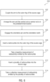
- a technician can couple the one or more arms of the frame to the source cage 602. As previously discussed, this can include simply securing a fixed frame on the outer ring of the source cage, or attaching an articulated frame via movable components (e.g. hinges). The technician can then arrange the arm and specifically, the central rod, until the gamma detector is in a predetermined location relative to a cylindrical volume defined by an outer ring of the source cage 604.
- the technician can engage the orientation pin of the frame and the orientation notch of the source cage 606.
- the device can include alternate components for initial alignment and coupling, as disclosed above. This will ensure that the gamma detector is properly positioned and secure for testing.
- the technician can install a single radionuclide of a plurality of radionuclides into the source cage. 608. Once installed, the technician can take a baseline measurement of the radioactivity emitted by the single radionuclide 610 and.can proceed to install each radionuclide to be shipped into the source cage 612. The technician can then take a collective measurement of radioactivity emitted by the entire shipment of radionuclides 614. The technician can then compare the collective measurement to the baseline measurement and determine a correction factor based, at least in part, on the comparison.
- the technician might expect that the collective measurement would be 48 Curies. However, if the collective measurement significantly diverges from the what would be expected based on the baseline measurement, the technician might determine a correction factor, which can account for an acceptable margin of error. Accordingly, the technician might decide to reposition the gamma detector within the cylindrical volume based, at least in part, on the determined correction factor. Without following the aforementioned steps of method 600, the technician would be forced to measure each radionuclide on a one-by-one basis, which is as costly as it is time-consuming. However, by following the aforementioned steps of the method 600, the technician can easily measure and adjustment the method of measurement and therefore, can efficiently acquire accurate data associated with the anticipated shipment.
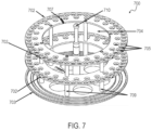
- FIG.7 a perspective view of another source cage 700 of a device configured to measure radioactivity emitted by a plurality of radionuclides in bulk is depicted in accordance with at least one non-limiting aspect of the present disclosure.
- the source cage 700 of FIG.7 is similarly configured to the source cage 100 of FIG.1 .
- the source cage 700 can further include a geometrical feature 710 positioned within the volume 704 defined by the outer rings 702 of the source cage 700.
- the source cage 700 of FIG.7 includes a base plate 703 coupled to the standoff rods 709 of the source cage 700, and the geometrical feature 710 includes a centerpiece extending up from the base plate 703 into the volume 704, where the central rod 208 ( FIG.2 ) of the frame 200 (200) could otherwise be positioned.
- a gamma detector- such as an ion chamber detector 207 ( FIG.2 )-can be suspended above the cylindrical volume 704 via a central rod 512 ( FIG.5 ) of a frame 500 ( FIG.5 ).
- a gamma detector- such as a self-powered detector 302 ( FIG.3 )-can be strategically positioned about the centerpiece 710, in accordance with the intended application and/or user preference.
- any reference to “one aspect,” “an aspect,” “an exemplification,” “one exemplification,” and the like means that a particular feature, structure, or characteristic described in connection with the aspect is included in at least one aspect.
- appearances of the phrases “in one aspect,” “in an aspect,” “in an exemplification,” and “in one exemplification” in various places throughout the specification are not necessarily all referring to the same aspect.
- the particular features, structures or characteristics may be combined in any suitable manner in one or more aspects.
- the terms “about” or “approximately” as used in the present disclosure means an acceptable error for a particular value as determined by one of ordinary skill in the art, which depends in part on how the value is measured or determined. In certain aspects, the term “about” or “approximately” means within 1, 2, 3, or 4 standard deviations. In certain aspects, the term “about” or “approximately” means within 50%, 200%, 105%, 100%, 9%, 8%, 7%, 6%, 5%, 4%, 3%, 2%, 1%, 0.5%, or 0.05% of a given value or range.
- any numerical range recited herein includes all sub-ranges subsumed within the recited range.
- a range of "1 to 100" includes all sub-ranges between (and including) the recited minimum value of 1 and the recited maximum value of 100, that is, having a minimum value equal to or greater than 1 and a maximum value equal to or less than 100.
- all ranges recited herein are inclusive of the end points of the recited ranges.
- a range of "1 to 100” includes the end points 1 and 100.
- Any maximum numerical limitation recited in this specification is intended to include all lower numerical limitations subsumed therein, and any minimum numerical limitation recited in this specification is intended to include all higher numerical limitations subsumed therein. Accordingly, Applicant reserves the right to amend this specification, including the claims, to expressly recite any sub-range subsumed within the ranges expressly recited. All such ranges are inherently described in this specification.
Landscapes
- Physics & Mathematics (AREA)
- Health & Medical Sciences (AREA)
- Life Sciences & Earth Sciences (AREA)
- General Physics & Mathematics (AREA)
- High Energy & Nuclear Physics (AREA)
- Molecular Biology (AREA)
- Spectroscopy & Molecular Physics (AREA)
- Chemical & Material Sciences (AREA)
- Analytical Chemistry (AREA)
- Measurement Of Radiation (AREA)
- Other Investigation Or Analysis Of Materials By Electrical Means (AREA)
Claims (17)
- Verfahren zur Messung der von einer Vielzahl von Radionukliden emittierten Radioaktivität unter Verwendung eines Quellenkäfigs (100; 402), umfassend einen Außenring (102; 406), der ein Volumen (104) und eine Vielzahl von Löchern (105) definiert, wobei jedes Loch von der Vielzahl von Löchern (105) dazu ausgestaltet ist, ein Radionuklid von der Vielzahl von Radionukliden (106) aufzunehmen, und einen Rahmen (200; 408), umfassend einen mit einem mittleren Stab (208; 412) gekoppelten Arm (201), wobei der mittlere Stab (208; 412) mit einem Gammadetektor (207; 414) gekoppelt ist, wobei der Außenring (102; 406) ein Ausrichtungsmerkmal (107; 422) umfasst, wobei der Arm (201) einen Ausrichtungsstift (420) umfasst, der dazu ausgestaltet ist, in das Ausrichtungsmerkmal (107; 422) einzugreifen, und wobei der mittlere Stab (208; 412) dazu ausgestaltet ist, in einer vorbestimmten Position relativ zu dem Volumen (104) positioniert zu sein, wenn sich der Ausrichtungsstift (420) und das Ausrichtungsmerkmal (107; 422) im Eingriff befinden, wobei das Verfahren umfasst:Koppeln (602) des Arms (201) mit dem Außenring (102; 406) des Quellenkäfigs (100; 402);Anordnen (604) des Arms (201) und des mittleren Stabs (208; 412), bis der mittlere Stab in der vorbestimmten Position relativ zum Volumen (104) positioniert ist;Eingreifen (606) des Ausrichtungsstifts (420) des Arms (201) und des Ausrichtungsmerkmals (107; 422) des Außenrings (102; 406) des Quellenkäfigs (100; 402);Einsetzen (608) eines Radionuklids von der Vielzahl von Radionukliden (106) in ein Loch von der Vielzahl von Löchern (105) des Außenrings (102; 406) des Quellenkäfigs (100; 402);Aufnehmen eines Basismesswerts (610) der von dem eingesetzten Radionuklid emittierten Radioaktivität unter Verwendung des Gammadetektors (207; 414);Entfernen des Radionuklids von der Vielzahl von Radionukliden (106) aus dem Loch von der Vielzahl von Löchern (105) des Außenrings (102; 406) des Quellenkäfigs (100; 402);
undEinsetzen (612) jedes Radionuklids von der Vielzahl von Radionukliden in die Vielzahl von Löchern (105) des Außenrings (102; 406) des Quellenkäfigs (100; 402);gekennzeichnet durchAufnehmen (614) eines Kollektivmesswerts von durch die Vielzahl von Radionukliden (106) emittierter Radioaktivität; undDividieren des Kollektivmesswerts durch die Anzahl von Radionukliden von der Vielzahl von Radionukliden (106), um einen Durchschnittsmesswert von durch jedes Radionuklid von der Vielzahl von Radionukliden (106) emittierter Radioaktivität zu bestimmen. - Verfahren nach Anspruch 1, ferner umfassend:Vergleichen des Durchschnittsmesswerts von durch jedes Radionuklid von derVielzahl von Radionukliden (106) emittierter Radioaktivität mit einem geschätzten Messwert von durch jedes Radionuklid von derVielzahl von Radionukliden emittierter Radioaktivität;Bestimmen eines Korrekturfaktors, basierend, mindestens teilweise, auf dem Vergleich des Durchschnittsmesswerts von durch jedes Radionuklid von derVielzahl von Radionukliden emittierter Radioaktivität mit dem geschätzten Messwert von durch jedes Radionuklid von der Vielzahl von Radionukliden emittierter Radioaktivität; undBestimmen einer zweiten vorbestimmten Position, basierend, mindestens teilweise, auf dem bestimmten Korrekturfaktor.
- Verfahren nach Anspruch 2, ferner umfassend:Ausrücken des Ausrichtungsstifts (420) des Arms (201) und des Ausrichtungsmerkmals (107; 422) des Außenrings (102; 406) des Quellenkäfigs (100; 402);Neuanordnen des Arms (201) und des mittleren Stabs (208; 412), bis der mittlere Stab in der zweiten vorbestimmten Position relativ zum Volumen (104) positioniert ist;Aufnehmen eines Korrekturmesswerts von durch die Vielzahl von Radionukliden (106) emittierter Radioaktivität; undDividieren des Korrekturmesswerts durch die Anzahl von Radionukliden von der Vielzahl von Radionukliden, um einen korrigierten Durchschnittsmesswert von durch jedes Radionuklid von der Vielzahl von Radionukliden emittierter Radioaktivität zu bestimmen.
- Verfahren nach Anspruch 2, wobei der Rahmen (200; 408) ferner einen zweiten Arm (202), gekoppelt mit dem mittleren Stab (208; 412), umfasst, wobei der Arm und der zweite Arm dazu ausgestaltet sind, bewegbar mit dem Außenring (102; 406) gekoppelt zu sein, wobei der Arm (201) und der zweite Arm (202) zwischen einer ersten Position relativ zum Quellenkäfig (100; 402) und einer zweiten Position relativ zum Quellenkäfig (100; 402) bewegbar sind, wobei das Verfahren ferner umfasst:Koppeln des zweiten Arms (202) mit dem Außenring (102; 406) des Quellenkäfigs (100; 402);Neuanordnen des Arms (201) und des zweiten Arms (202) von der ersten Position in die zweite Position, bis der mittlere Stab (208; 412) in der zweiten vorbestimmten Position relativ zum Volumen (104) positioniert ist;Aufnehmen eines Korrekturmesswerts von durch die Vielzahl von Radionukliden (106) emittierter Radioaktivität; undDividieren des Korrekturmesswerts durch die Anzahl von Radionukliden von der Vielzahl von Radionukliden (106), um einen korrigierten Durchschnittsmesswert von durch jedes Radionuklid von der Vielzahl von Radionukliden (106) emittierter Radioaktivität zu bestimmen.
- Verfahren nach Anspruch 1, ferner umfassend das Untertauchen des Quellenkäfigs (100; 402) in ein Fluid, und wobei das Anordnen des Arms (201) und des mittleren Stabs (208; 412) ferner das Verwenden eines Handhabungsarms (418) umfasst, der dazu ausgestaltet ist, einem Techniker zu erlauben, den Ausrichtungsstift (420) und das Ausrichtungsmerkmal (107; 422) aus einer vorbestimmten Entfernung, von der Vielzahl von Radionukliden (106) entfernt, einzurücken.
- Vorrichtung, dazu ausgestaltet, von einer Vielzahl von Radionukliden (106) emittierte Radioaktivität zu messen, gekoppelt mit einem Quellenkäfig (100; 402), der ein Volumen (104) definiert, wobei der Quellenkäfig (100; 402) ein Ausrichtungsmerkmal (107; 422) umfasst, wobei die Vorrichtung Folgendes umfasst:einen Arm (201), dazu ausgestaltet, mit dem Quellenkäfig (100; 402) gekoppelt zu sein, wobei der Arm (201) eine Ausrichtungskomponente (420) umfasst, die dem Ausrichtungsmerkmal (107; 422) des Quellenkäfigs (100; 402) entspricht; undeinen mittleren Stab (208; 412), gekoppelt mit dem Arm (201), wobei der mittlere Stab (208; 412) dazu ausgestaltet ist, relativ zum Volumen (104) des Quellenkäfigs (100; 402) positioniert zu sein, wenn der Arm (201) mit dem Quellenkäfig (100; 402) gekoppelt ist;wobei das Ausrichtungsmerkmal (107; 422) bezeichnend für eine vorbestimmte Position relativ zur Ausrichtungskomponente (420) an dem Quellenkäfig (100; 402) ist, und wobei die vorbestimmte Position relativ zur Ausrichtungskomponente (420) an dem Quellenkäfig (100; 402) einer vorbestimmten Position relativ zum mittleren Stab (208; 412) relativ zum Volumen (104) entspricht;gekennzeichnet durcheinen Gammadetektor (207; 414), gekoppelt mit dem mittleren Stab (208; 412), wobei der Gammadetektor (207; 414) dazu ausgestaltet ist, die von der Vielzahl von Radionukliden (106) emittierte Radioaktivität zu messen.
- Vorrichtung nach Anspruch 6, ferner umfassend einen zweiten Arm (202), gekoppelt mit dem mittleren Stab (208; 412), wobei der Arm (201) und der zweite Arm (202) bewegbar mit dem Quellenkäfig (100; 402) gekoppelt sind, wobei der Arm (201) und der zweite Arm (202) zwischen einer ersten Position relativ zum Quellenkäfig (100; 402) und einer zweiten Position relativ zum Quellenkäfig (100; 402) bewegbar sind, wobei der mittlere Stab (208; 412) in der vorbestimmten Position relativ zum Volumen (104) positioniert ist, wenn der Arm (201) und der zweite Arm (202) in der ersten Position sind, und wobei der mittlere Stab (208; 412) in einer zweiten vorbestimmten Position relativ zum Volumen (104) positioniert ist, wenn der Arm (201) und der zweite Arm (202) in der zweiten Position sind.
- Vorrichtung nach Anspruch 6, ferner umfassend einen Handhabungsarm (418), umfassend eine Länge, wobei der Handhabungsarm (418) dazu ausgestaltet ist, einem Techniker zu erlauben, die Ausrichtungskomponente (420) relativ zu dem Ausrichtungsmerkmal (107; 422) auszurichten, und wobei die Länge speziell dazu ausgestaltet ist, den Techniker in einer vorbestimmten Entfernung von der Vielzahl von Radionukliden (106) weg zu positionieren.
- Vorrichtung nach Anspruch 6, wobei der Gammadetektor (207; 414) eine Spirale umfasst, die um ein Rohr gewickelt ist, das dazu ausgestaltet ist, mit dem mittleren Stab (208; 412) gekoppelt zu sein.
- Vorrichtung nach Anspruch 6, umfassend:einen Rahmen (200; 408), umfassend den Arm (201) und den mittleren Stab (208; 412);wobei der Quellenkäfig (100; 402) einen Außenring (102; 406) umfasst, der das Volumen (104) und das Ausrichtungsmerkmal (107; 422) definiert, wobei der Außenring (102; 406) eine Vielzahl von Löchern (105) umfasst, wobei jedes Loch von der Vielzahl von Löchern (105) dazu ausgestaltet ist, ein Radionuklid von der Vielzahl von Radionukliden (106) aufzunehmen; undder Arm (201) einen Ausrichtungsstift (420) umfasst; unddas Ausrichtungsmerkmal (107; 422) des Quellenkäfigs (100; 402) dazu ausgestaltet ist, in den Ausrichtungsstift (420) des Arms (201) einzugreifen, und wobei der mittlere Stab (208; 412) in einer vorbestimmten Position relativ zum Volumen (104) positioniert ist, wenn der Ausrichtungsstift (420) in das Ausrichtungsmerkmal (107; 422) eingreift.
- Vorrichtung nach Anspruch 10, wobei der Gammadetektor (207; 414) ferner eine Gammaabschirmung umfasst, die dazu ausgestaltet ist, eine Quantität von durch den Gammadetektor (207; 414) emittierter Radioaktivität zu reduzieren.
- Vorrichtung nach Anspruch 10, wobei der Rahmen (200; 408) ferner einen zweiten Arm (202), gekoppelt mit dem mittleren Stab (208; 412), umfasst, wobei der Arm (201) und der zweite Arm (202) bewegbar mit dem Außenring (102; 406) gekoppelt sind, wobei der Arm (201) und der zweite Arm (202) zwischen einer ersten Position relativ zum Quellenkäfig (100; 402) und einer zweiten Position relativ zum Quellenkäfig (100; 402) bewegbar sind, wobei der mittlere Stab (208; 412) in der vorbestimmten Position relativ zum Volumen (104) positioniert ist, wenn der Arm (201) und derzweite Arm (202) in der ersten Position sind, und wobei der mittlere Stab (208; 412) in einer zweiten vorbestimmten Position relativ zum Volumen (104) positioniert ist, wenn der Arm (201) und der zweite Arm (202) in der zweiten Position sind.
- Vorrichtung nach Anspruch 10, wobei der Gammadetektor (207; 414) eine Farmerlonenkammer (207) umfasst.
- Vorrichtung nach Anspruch 13, ferner umfassend ein Gehäuse, dazu ausgestaltet, mit dem mittleren Stab (208; 412) gekoppelt zu sein, wobei die Farmer-Ionenkammer mit einer Oberseite des Gehäuses gekoppelt ist, und wobei der Gammadetektor (207; 414) in der Mitte des Volumens (104) ausgerichtet ist, wenn das Gehäuse mit dem mittleren Stab (208; 412) gekoppelt ist.
- Vorrichtung nach Anspruch 10, wobei der Quellenkäfig (100; 402) ein in dem Volumen (104) positioniertes geometrisches Merkmal umfasst, wobei der Gammadetektor (207; 414) mit dem geometrischen Merkmal gekoppelt ist, und wobei der Gammadetektor (207; 414) einen Detektor (302) ohne äußere Energieversorgung umfasst, beispielsweise einen Detektor ohne äußere Energieversorgung, der eine um das geometrische Merkmal des Quellenkäfigs (100; 402) gewickelte Spirale umfasst.
- Vorrichtung nach Anspruch 10, ferner umfassend eine Hülse, dazu ausgestaltet, den Gammadetektor (207; 414) mit dem mittleren Stab (208; 412) zu koppeln.
- Vorrichtung nach Anspruch 10, ferner umfassend einen Handhabungsarm (201), umfassend eine Länge, wobei der Handhabungsarm (418) dazu ausgestaltet ist, einem Techniker zu erlauben, den Ausrichtungsstift (420) und das Ausrichtungsmerkmal (107; 422) einzurücken, und wobei die Länge speziell dazu ausgestaltet ist, den Techniker in einer vorbestimmten Entfernung von derVielzahl von Radionukliden (106) weg zu positionieren.
Priority Applications (1)
| Application Number | Priority Date | Filing Date | Title |
|---|---|---|---|
| EP25150269.6A EP4538750A3 (de) | 2020-10-21 | 2021-10-20 | Vorrichtungen, systeme und verfahren zur messung der produktion radioaktiver isotope in masse |
Applications Claiming Priority (2)
| Application Number | Priority Date | Filing Date | Title |
|---|---|---|---|
| US17/076,500 US11340178B1 (en) | 2020-10-01 | 2020-10-21 | Devices, systems, and methods for measuring radioactive isotope production in bulk |
| PCT/US2021/071940 WO2022087595A1 (en) | 2020-10-21 | 2021-10-20 | Devices, systems, and methods for measuring radioactive isotope production in bulk |
Related Child Applications (1)
| Application Number | Title | Priority Date | Filing Date |
|---|---|---|---|
| EP25150269.6A Division EP4538750A3 (de) | 2020-10-21 | 2021-10-20 | Vorrichtungen, systeme und verfahren zur messung der produktion radioaktiver isotope in masse |
Publications (2)
| Publication Number | Publication Date |
|---|---|
| EP4232829A1 EP4232829A1 (de) | 2023-08-30 |
| EP4232829B1 true EP4232829B1 (de) | 2025-01-08 |
Family
ID=78622135
Family Applications (2)
| Application Number | Title | Priority Date | Filing Date |
|---|---|---|---|
| EP25150269.6A Pending EP4538750A3 (de) | 2020-10-21 | 2021-10-20 | Vorrichtungen, systeme und verfahren zur messung der produktion radioaktiver isotope in masse |
| EP21807485.4A Active EP4232829B1 (de) | 2020-10-21 | 2021-10-20 | Vorrichtungen, systeme und verfahren zur messung der produktion radioaktiver isotope in masse |
Family Applications Before (1)
| Application Number | Title | Priority Date | Filing Date |
|---|---|---|---|
| EP25150269.6A Pending EP4538750A3 (de) | 2020-10-21 | 2021-10-20 | Vorrichtungen, systeme und verfahren zur messung der produktion radioaktiver isotope in masse |
Country Status (10)
| Country | Link |
|---|---|
| EP (2) | EP4538750A3 (de) |
| JP (1) | JP7752173B2 (de) |
| KR (1) | KR20230091904A (de) |
| CN (1) | CN116490779A (de) |
| CA (1) | CA3196207A1 (de) |
| ES (1) | ES3023585T3 (de) |
| FI (1) | FI4232829T3 (de) |
| HU (1) | HUE071090T2 (de) |
| TW (1) | TWI810686B (de) |
| WO (1) | WO2022087595A1 (de) |
Family Cites Families (10)
| Publication number | Priority date | Publication date | Assignee | Title |
|---|---|---|---|---|
| GB884349A (en) * | 1959-04-10 | 1961-12-13 | Packard Instrument Co Inc | Radioactivity measuring apparatus |
| US2924718A (en) * | 1959-04-10 | 1960-02-09 | Packard Instrument Co Inc | Radioactivity measuring apparatus |
| US3141977A (en) * | 1959-07-29 | 1964-07-21 | Lab For Electronics Inc | Apparatus for measuring the radioactivity of liquid samples |
| US3271574A (en) * | 1963-04-16 | 1966-09-06 | Vanguard Instr Corp | Data handling and control circuit for liquid scintillation spectrometers |
| FR1394417A (fr) * | 1964-04-14 | 1965-04-02 | Packard Instrument Co Inc | Perfectionnements apportés à l'analyse de la radioactivité des échantillons multiples |
| JPH10123069A (ja) * | 1996-10-21 | 1998-05-15 | Pure Retsukusu:Kk | 半導体シリコン試料放射化分析での多数同時処理法 |
| JP5905672B2 (ja) * | 2011-06-28 | 2016-04-20 | 株式会社東芝 | 放射線検出器及びその製造方法 |
| JP6218352B2 (ja) * | 2011-12-15 | 2017-10-25 | 株式会社島津製作所 | 測定システムに用いられる表示装置、表示方法並びに表示プログラム |
| JP5925711B2 (ja) * | 2013-02-20 | 2016-05-25 | 浜松ホトニクス株式会社 | 検出器、pet装置及びx線ct装置 |
| JP6246003B2 (ja) * | 2014-01-30 | 2017-12-13 | 日立Geニュークリア・エナジー株式会社 | 放射線計測装置及びそれを用いた燃料デブリの有無及び位置測定装置並びに燃料デブリの有無及び位置測定方法 |
-
2021
- 2021-10-20 JP JP2023524194A patent/JP7752173B2/ja active Active
- 2021-10-20 CA CA3196207A patent/CA3196207A1/en active Pending
- 2021-10-20 ES ES21807485T patent/ES3023585T3/es active Active
- 2021-10-20 FI FIEP21807485.4T patent/FI4232829T3/fi active
- 2021-10-20 WO PCT/US2021/071940 patent/WO2022087595A1/en not_active Ceased
- 2021-10-20 EP EP25150269.6A patent/EP4538750A3/de active Pending
- 2021-10-20 EP EP21807485.4A patent/EP4232829B1/de active Active
- 2021-10-20 HU HUE21807485A patent/HUE071090T2/hu unknown
- 2021-10-20 CN CN202180071925.3A patent/CN116490779A/zh active Pending
- 2021-10-20 KR KR1020237013657A patent/KR20230091904A/ko active Pending
- 2021-10-21 TW TW110139155A patent/TWI810686B/zh active
Also Published As
| Publication number | Publication date |
|---|---|
| TWI810686B (zh) | 2023-08-01 |
| EP4232829A1 (de) | 2023-08-30 |
| JP7752173B2 (ja) | 2025-10-09 |
| KR20230091904A (ko) | 2023-06-23 |
| EP4538750A3 (de) | 2025-05-07 |
| CA3196207A1 (en) | 2022-04-28 |
| FI4232829T3 (fi) | 2025-04-09 |
| JP2023547613A (ja) | 2023-11-13 |
| CN116490779A (zh) | 2023-07-25 |
| TW202223439A (zh) | 2022-06-16 |
| EP4538750A2 (de) | 2025-04-16 |
| WO2022087595A1 (en) | 2022-04-28 |
| HUE071090T2 (hu) | 2025-08-28 |
| ES3023585T3 (en) | 2025-06-02 |
Similar Documents
| Publication | Publication Date | Title |
|---|---|---|
| JPS6222878Y2 (de) | ||
| ES2998087T3 (en) | Method and device for the quantification of radionuclides in liquid media | |
| US11340178B1 (en) | Devices, systems, and methods for measuring radioactive isotope production in bulk | |
| EP4538750A2 (de) | Vorrichtungen, systeme und verfahren zur messung der produktion radioaktiver isotope in masse | |
| US20220107429A1 (en) | Devices, systems, and methods for measuring radioactive isotope production in bulk | |
| US20010052571A1 (en) | Multiple-eye type dose distribution measuring method | |
| CN103026264B (zh) | 用于监视位于手套箱中的核材料的设备 | |
| Lévai et al. | Feasibility of gamma emission tomography for partial defect verification of spent LWR fuel assemblies: Summary report on simulation and experimental studies including design options and cost-benefit analysis: Task JNT A1201 of the Support Programmes of Finland (FINSP), Hungary (HUNSP) and Sweden (SWESP) to the IAEA Safeguards | |
| CN112764078B (zh) | 一种核物料测量装置 | |
| Thiollay et al. | FLUOLE-2: An experiment for PWR pressure vessel surveillance | |
| ES2351020B1 (es) | Escaner para el analisis de una barra de combustible nuclear. | |
| CN219590524U (zh) | 一种高纯锗谱仪样品支架 | |
| Elísio et al. | Point-spread analysis of γ-ray/depth spectra for borehole monitoring applications | |
| CN111566470B (zh) | 用于处理出自核反应堆的经辐射的靶的靶平台 | |
| KR102321898B1 (ko) | 광역에너지 검출용 중성자 계측장비 | |
| JP5020559B2 (ja) | 燃料棒検査方法および燃料棒検査装置 | |
| Berndt et al. | Spent-fuel characterization with small CZT detectors | |
| JP6282540B2 (ja) | 放射能濃度測定システム | |
| Bushuev et al. | A setup for active neutron analysis of the fissile material content in fuel assemblies of nuclear reactors | |
| KR20160123157A (ko) | 핵연료봉 탐상장치 | |
| Abhold et al. | RRFC hardware operation manual | |
| Heinrich | Delayed neutrons from the neutron irradiation of ²³⁵U | |
| KR100728705B1 (ko) | 방사성 동위원소의 생산을 위한 lh 플러그와 lh 리그및 이를 인, 입출하기 위한 공구 | |
| Ichim et al. | Examination of irradiated fuel elements using gamma scanning technique | |
| CN119045035A (zh) | 一种立式炉内滞留量测量装置及测量方法 |
Legal Events
| Date | Code | Title | Description |
|---|---|---|---|
| STAA | Information on the status of an ep patent application or granted ep patent |
Free format text: STATUS: UNKNOWN |
|
| STAA | Information on the status of an ep patent application or granted ep patent |
Free format text: STATUS: THE INTERNATIONAL PUBLICATION HAS BEEN MADE |
|
| PUAI | Public reference made under article 153(3) epc to a published international application that has entered the european phase |
Free format text: ORIGINAL CODE: 0009012 |
|
| STAA | Information on the status of an ep patent application or granted ep patent |
Free format text: STATUS: REQUEST FOR EXAMINATION WAS MADE |
|
| 17P | Request for examination filed |
Effective date: 20230522 |
|
| AK | Designated contracting states |
Kind code of ref document: A1 Designated state(s): AL AT BE BG CH CY CZ DE DK EE ES FI FR GB GR HR HU IE IS IT LI LT LU LV MC MK MT NL NO PL PT RO RS SE SI SK SM TR |
|
| DAV | Request for validation of the european patent (deleted) | ||
| DAX | Request for extension of the european patent (deleted) | ||
| STAA | Information on the status of an ep patent application or granted ep patent |
Free format text: STATUS: EXAMINATION IS IN PROGRESS |
|
| 17Q | First examination report despatched |
Effective date: 20240221 |
|
| GRAP | Despatch of communication of intention to grant a patent |
Free format text: ORIGINAL CODE: EPIDOSNIGR1 |
|
| STAA | Information on the status of an ep patent application or granted ep patent |
Free format text: STATUS: GRANT OF PATENT IS INTENDED |
|
| INTG | Intention to grant announced |
Effective date: 20240812 |
|
| GRAS | Grant fee paid |
Free format text: ORIGINAL CODE: EPIDOSNIGR3 |
|
| GRAA | (expected) grant |
Free format text: ORIGINAL CODE: 0009210 |
|
| STAA | Information on the status of an ep patent application or granted ep patent |
Free format text: STATUS: THE PATENT HAS BEEN GRANTED |
|
| AK | Designated contracting states |
Kind code of ref document: B1 Designated state(s): AL AT BE BG CH CY CZ DE DK EE ES FI FR GB GR HR HU IE IS IT LI LT LU LV MC MK MT NL NO PL PT RO RS SE SI SK SM TR |
|
| REG | Reference to a national code |
Ref country code: GB Ref legal event code: FG4D |
|
| REG | Reference to a national code |
Ref country code: CH Ref legal event code: EP |
|
| REG | Reference to a national code |
Ref country code: DE Ref legal event code: R096 Ref document number: 602021024761 Country of ref document: DE |
|
| REG | Reference to a national code |
Ref country code: IE Ref legal event code: FG4D |
|
| REG | Reference to a national code |
Ref country code: FI Ref legal event code: FGE |
|
| REG | Reference to a national code |
Ref country code: SE Ref legal event code: TRGR |
|
| REG | Reference to a national code |
Ref country code: LT Ref legal event code: MG9D |
|
| REG | Reference to a national code |
Ref country code: NL Ref legal event code: MP Effective date: 20250108 |
|
| REG | Reference to a national code |
Ref country code: ES Ref legal event code: FG2A Ref document number: 3023585 Country of ref document: ES Kind code of ref document: T3 Effective date: 20250602 |
|
| REG | Reference to a national code |
Ref country code: AT Ref legal event code: MK05 Ref document number: 1758644 Country of ref document: AT Kind code of ref document: T Effective date: 20250108 |
|
| PG25 | Lapsed in a contracting state [announced via postgrant information from national office to epo] |
Ref country code: NL Free format text: LAPSE BECAUSE OF FAILURE TO SUBMIT A TRANSLATION OF THE DESCRIPTION OR TO PAY THE FEE WITHIN THE PRESCRIBED TIME-LIMIT Effective date: 20250108 |
|
| PG25 | Lapsed in a contracting state [announced via postgrant information from national office to epo] |
Ref country code: RS Free format text: LAPSE BECAUSE OF FAILURE TO SUBMIT A TRANSLATION OF THE DESCRIPTION OR TO PAY THE FEE WITHIN THE PRESCRIBED TIME-LIMIT Effective date: 20250408 |
|
| PG25 | Lapsed in a contracting state [announced via postgrant information from national office to epo] |
Ref country code: PL Free format text: LAPSE BECAUSE OF FAILURE TO SUBMIT A TRANSLATION OF THE DESCRIPTION OR TO PAY THE FEE WITHIN THE PRESCRIBED TIME-LIMIT Effective date: 20250108 |
|
| PG25 | Lapsed in a contracting state [announced via postgrant information from national office to epo] |
Ref country code: NO Free format text: LAPSE BECAUSE OF FAILURE TO SUBMIT A TRANSLATION OF THE DESCRIPTION OR TO PAY THE FEE WITHIN THE PRESCRIBED TIME-LIMIT Effective date: 20250408 Ref country code: IS Free format text: LAPSE BECAUSE OF FAILURE TO SUBMIT A TRANSLATION OF THE DESCRIPTION OR TO PAY THE FEE WITHIN THE PRESCRIBED TIME-LIMIT Effective date: 20250508 |
|
| PG25 | Lapsed in a contracting state [announced via postgrant information from national office to epo] |
Ref country code: HR Free format text: LAPSE BECAUSE OF FAILURE TO SUBMIT A TRANSLATION OF THE DESCRIPTION OR TO PAY THE FEE WITHIN THE PRESCRIBED TIME-LIMIT Effective date: 20250108 |
|
| PG25 | Lapsed in a contracting state [announced via postgrant information from national office to epo] |
Ref country code: PT Free format text: LAPSE BECAUSE OF FAILURE TO SUBMIT A TRANSLATION OF THE DESCRIPTION OR TO PAY THE FEE WITHIN THE PRESCRIBED TIME-LIMIT Effective date: 20250508 Ref country code: LV Free format text: LAPSE BECAUSE OF FAILURE TO SUBMIT A TRANSLATION OF THE DESCRIPTION OR TO PAY THE FEE WITHIN THE PRESCRIBED TIME-LIMIT Effective date: 20250108 |
|
| PG25 | Lapsed in a contracting state [announced via postgrant information from national office to epo] |
Ref country code: GR Free format text: LAPSE BECAUSE OF FAILURE TO SUBMIT A TRANSLATION OF THE DESCRIPTION OR TO PAY THE FEE WITHIN THE PRESCRIBED TIME-LIMIT Effective date: 20250409 |
|
| PG25 | Lapsed in a contracting state [announced via postgrant information from national office to epo] |
Ref country code: AT Free format text: LAPSE BECAUSE OF FAILURE TO SUBMIT A TRANSLATION OF THE DESCRIPTION OR TO PAY THE FEE WITHIN THE PRESCRIBED TIME-LIMIT Effective date: 20250108 |
|
| REG | Reference to a national code |
Ref country code: HU Ref legal event code: AG4A Ref document number: E071090 Country of ref document: HU |
|
| PG25 | Lapsed in a contracting state [announced via postgrant information from national office to epo] |
Ref country code: SM Free format text: LAPSE BECAUSE OF FAILURE TO SUBMIT A TRANSLATION OF THE DESCRIPTION OR TO PAY THE FEE WITHIN THE PRESCRIBED TIME-LIMIT Effective date: 20250108 |
|
| PGFP | Annual fee paid to national office [announced via postgrant information from national office to epo] |
Ref country code: FI Payment date: 20250919 Year of fee payment: 5 |
|
| REG | Reference to a national code |
Ref country code: DE Ref legal event code: R097 Ref document number: 602021024761 Country of ref document: DE |
|
| PG25 | Lapsed in a contracting state [announced via postgrant information from national office to epo] |
Ref country code: DK Free format text: LAPSE BECAUSE OF FAILURE TO SUBMIT A TRANSLATION OF THE DESCRIPTION OR TO PAY THE FEE WITHIN THE PRESCRIBED TIME-LIMIT Effective date: 20250108 |
|
| PGFP | Annual fee paid to national office [announced via postgrant information from national office to epo] |
Ref country code: BG Payment date: 20250926 Year of fee payment: 5 |
|
| PG25 | Lapsed in a contracting state [announced via postgrant information from national office to epo] |
Ref country code: EE Free format text: LAPSE BECAUSE OF FAILURE TO SUBMIT A TRANSLATION OF THE DESCRIPTION OR TO PAY THE FEE WITHIN THE PRESCRIBED TIME-LIMIT Effective date: 20250108 |
|
| PG25 | Lapsed in a contracting state [announced via postgrant information from national office to epo] |
Ref country code: RO Free format text: LAPSE BECAUSE OF FAILURE TO SUBMIT A TRANSLATION OF THE DESCRIPTION OR TO PAY THE FEE WITHIN THE PRESCRIBED TIME-LIMIT Effective date: 20250108 |
|
| PG25 | Lapsed in a contracting state [announced via postgrant information from national office to epo] |
Ref country code: SK Free format text: LAPSE BECAUSE OF FAILURE TO SUBMIT A TRANSLATION OF THE DESCRIPTION OR TO PAY THE FEE WITHIN THE PRESCRIBED TIME-LIMIT Effective date: 20250108 |
|
| PGFP | Annual fee paid to national office [announced via postgrant information from national office to epo] |
Ref country code: HU Payment date: 20250930 Year of fee payment: 5 |
|
| PLBE | No opposition filed within time limit |
Free format text: ORIGINAL CODE: 0009261 |
|
| STAA | Information on the status of an ep patent application or granted ep patent |
Free format text: STATUS: NO OPPOSITION FILED WITHIN TIME LIMIT |
|
| 26N | No opposition filed |
Effective date: 20251009 |
|
| PGFP | Annual fee paid to national office [announced via postgrant information from national office to epo] |
Ref country code: DE Payment date: 20250919 Year of fee payment: 5 |
|
| PGFP | Annual fee paid to national office [announced via postgrant information from national office to epo] |
Ref country code: GB Payment date: 20251024 Year of fee payment: 5 |
|
| PGFP | Annual fee paid to national office [announced via postgrant information from national office to epo] |
Ref country code: FR Payment date: 20251017 Year of fee payment: 5 |
|
| PGFP | Annual fee paid to national office [announced via postgrant information from national office to epo] |
Ref country code: SE Payment date: 20251017 Year of fee payment: 5 |
|
| PGFP | Annual fee paid to national office [announced via postgrant information from national office to epo] |
Ref country code: CZ Payment date: 20250930 Year of fee payment: 5 |
|
| PG25 | Lapsed in a contracting state [announced via postgrant information from national office to epo] |
Ref country code: IT Free format text: LAPSE BECAUSE OF FAILURE TO SUBMIT A TRANSLATION OF THE DESCRIPTION OR TO PAY THE FEE WITHIN THE PRESCRIBED TIME-LIMIT Effective date: 20250108 |
|
| PGFP | Annual fee paid to national office [announced via postgrant information from national office to epo] |
Ref country code: ES Payment date: 20251113 Year of fee payment: 5 |