EP4232741B1 - Improved insulated coupling - Google Patents
Improved insulated coupling Download PDFInfo
- Publication number
- EP4232741B1 EP4232741B1 EP22783068.4A EP22783068A EP4232741B1 EP 4232741 B1 EP4232741 B1 EP 4232741B1 EP 22783068 A EP22783068 A EP 22783068A EP 4232741 B1 EP4232741 B1 EP 4232741B1
- Authority
- EP
- European Patent Office
- Prior art keywords
- coupling
- seal
- liquefied gas
- lock position
- warm
- Prior art date
- Legal status (The legal status is an assumption and is not a legal conclusion. Google has not performed a legal analysis and makes no representation as to the accuracy of the status listed.)
- Active
Links
Images


Classifications
-
- F—MECHANICAL ENGINEERING; LIGHTING; HEATING; WEAPONS; BLASTING
- F16—ENGINEERING ELEMENTS AND UNITS; GENERAL MEASURES FOR PRODUCING AND MAINTAINING EFFECTIVE FUNCTIONING OF MACHINES OR INSTALLATIONS; THERMAL INSULATION IN GENERAL
- F16L—PIPES; JOINTS OR FITTINGS FOR PIPES; SUPPORTS FOR PIPES, CABLES OR PROTECTIVE TUBING; MEANS FOR THERMAL INSULATION IN GENERAL
- F16L59/00—Thermal insulation in general
- F16L59/14—Arrangements for the insulation of pipes or pipe systems
- F16L59/141—Arrangements for the insulation of pipes or pipe systems in which the temperature of the medium is below that of the ambient temperature
-
- F—MECHANICAL ENGINEERING; LIGHTING; HEATING; WEAPONS; BLASTING
- F16—ENGINEERING ELEMENTS AND UNITS; GENERAL MEASURES FOR PRODUCING AND MAINTAINING EFFECTIVE FUNCTIONING OF MACHINES OR INSTALLATIONS; THERMAL INSULATION IN GENERAL
- F16L—PIPES; JOINTS OR FITTINGS FOR PIPES; SUPPORTS FOR PIPES, CABLES OR PROTECTIVE TUBING; MEANS FOR THERMAL INSULATION IN GENERAL
- F16L37/00—Couplings of the quick-acting type
- F16L37/28—Couplings of the quick-acting type with fluid cut-off means
- F16L37/30—Couplings of the quick-acting type with fluid cut-off means with fluid cut-off means in each of two pipe-end fittings
- F16L37/36—Couplings of the quick-acting type with fluid cut-off means with fluid cut-off means in each of two pipe-end fittings with two lift valves being actuated to initiate the flow through the coupling after the two coupling parts are locked against withdrawal
-
- F—MECHANICAL ENGINEERING; LIGHTING; HEATING; WEAPONS; BLASTING
- F16—ENGINEERING ELEMENTS AND UNITS; GENERAL MEASURES FOR PRODUCING AND MAINTAINING EFFECTIVE FUNCTIONING OF MACHINES OR INSTALLATIONS; THERMAL INSULATION IN GENERAL
- F16L—PIPES; JOINTS OR FITTINGS FOR PIPES; SUPPORTS FOR PIPES, CABLES OR PROTECTIVE TUBING; MEANS FOR THERMAL INSULATION IN GENERAL
- F16L39/00—Joints or fittings for double-walled or multi-channel pipes or pipe assemblies
- F16L39/005—Joints or fittings for double-walled or multi-channel pipes or pipe assemblies for concentric pipes
-
- F—MECHANICAL ENGINEERING; LIGHTING; HEATING; WEAPONS; BLASTING
- F16—ENGINEERING ELEMENTS AND UNITS; GENERAL MEASURES FOR PRODUCING AND MAINTAINING EFFECTIVE FUNCTIONING OF MACHINES OR INSTALLATIONS; THERMAL INSULATION IN GENERAL
- F16L—PIPES; JOINTS OR FITTINGS FOR PIPES; SUPPORTS FOR PIPES, CABLES OR PROTECTIVE TUBING; MEANS FOR THERMAL INSULATION IN GENERAL
- F16L59/00—Thermal insulation in general
- F16L59/06—Arrangements using an air layer or vacuum
- F16L59/065—Arrangements using an air layer or vacuum using vacuum
-
- F—MECHANICAL ENGINEERING; LIGHTING; HEATING; WEAPONS; BLASTING
- F16—ENGINEERING ELEMENTS AND UNITS; GENERAL MEASURES FOR PRODUCING AND MAINTAINING EFFECTIVE FUNCTIONING OF MACHINES OR INSTALLATIONS; THERMAL INSULATION IN GENERAL
- F16L—PIPES; JOINTS OR FITTINGS FOR PIPES; SUPPORTS FOR PIPES, CABLES OR PROTECTIVE TUBING; MEANS FOR THERMAL INSULATION IN GENERAL
- F16L2201/00—Special arrangements for pipe couplings
- F16L2201/20—Safety or protective couplings
-
- F—MECHANICAL ENGINEERING; LIGHTING; HEATING; WEAPONS; BLASTING
- F16—ENGINEERING ELEMENTS AND UNITS; GENERAL MEASURES FOR PRODUCING AND MAINTAINING EFFECTIVE FUNCTIONING OF MACHINES OR INSTALLATIONS; THERMAL INSULATION IN GENERAL
- F16L—PIPES; JOINTS OR FITTINGS FOR PIPES; SUPPORTS FOR PIPES, CABLES OR PROTECTIVE TUBING; MEANS FOR THERMAL INSULATION IN GENERAL
- F16L59/00—Thermal insulation in general
- F16L59/14—Arrangements for the insulation of pipes or pipe systems
- F16L59/16—Arrangements specially adapted to local requirements at flanges, junctions, valves or the like
- F16L59/18—Arrangements specially adapted to local requirements at flanges, junctions, valves or the like adapted for joints
- F16L59/182—Joints with sleeve or socket
Definitions
- the present invention relates to an improved coupling for transfer of liquefied gas enabling secure purging of the volume between a first and second part of the coupling.
- the warm seal is engaged such that, in the second lock position, the warm seal is located between the purge opening and the connection point, and the warm seal is engaged such that the warm seal is located between the purge opening and the connection point.
- the warm and cold seals are annular seals.
- the locking device comprises an actuatable lock preventing the coupling from passing the first lock position without actuation of the lock.
- the entire coupling may comprise only one valve at each side, the reason for this is that the warm and cold seal creates additional safety barriers. Further, by introducing the first lock position disabling complete disconnection of the coupling without a soft or hard stop in the purging position, leakage in any one of the valve arrangements may be detected via the purge opening before complete disconnection.
- the emergency release device is separate from the locking device such that upon emergency release at least one part of the second part is separated and instead attached to the first part after separation.
- the first part comprises a first valve arrangement with a valve comprising a stem and a valve head
- the second part comprise a second valve arrangement with a valve comprising a stem and a valve head, wherein one of said valves is spring-loaded and the other of said valves is arranged in a fixed position in the valve arrangement.
- Figure 1 illustrates one embodiment of a coupling 1 wherein the first part 11 and second part 12 are shown.
- the first part 11 is a male part and the second part 12 is a female part, wherein the first part is adapted for insertion into the second part.
- the first part 11 is mostly installed on a vehicle, fuel tank, bunker vessel, or any other suitable unit for receiving the liquefied gas.
- the second part 12 is most likely installed on a fuel station, transport unit, rail car, tank truck, or similar unit for dispatching the liquefied gas.
- a fuel station transport unit
- rail car rail car
- tank truck or similar unit for dispatching the liquefied gas.
- other arrangements are also possible within the scope of the solution as described herein.
- Figure 1 further illustrates one embodiment of the solution wherein the coupling 1 is engaged by align rollers 6b1 to the entrances of a cam curves 6a1.
- This solution provides distinctive steps to achieve the first and second lock positions, however it should be noted that other solutions are possible as well.
- the user pulls the locking device button and push the second part 12 being hose unit forward to engage the rollers into the cam curve. Then turn for example 5 to 10 degrees until the locking device will lock into a locking hole.
- the rollers keep second part 12 connected to the first part 11 in the first lock position, also called the purge position.
- a locking pin is locking in the locking hole.
- the first section 6a of the locking device 6 comprises a number of cam curves 6a1 and the second section 6b of the locking device 6 comprises a number of rollers 6b1.
- Each curve 6a1 gets into contact with a roller 6b1 when the sections 6a and 6b of the locking device 6 are in contact with each other.
- the sections 6a and 6b are turned in relation to each other and each roller 6b1 will run in respective cam curve 6a1 until they, and the locking device 6, reach a first lock position.
- This is a purge position and in one embodiment movement out of the first lock position is prevented by an actuator 6e. If actuated, the actuator 6e allows further movement, either towards disconnection or towards the second lock position.
- each roller 6b1 When the sections 6a and 6b is turned further in relation to each other, each roller 6b1 will continue to run in respective cam curve 6a1 until they reach a final stop end position, the second lock position.
- the actuator 6e of the locking device 6 comes into an end position and locks the first part 11 and the second part 12 of the coupling 1 to each other.
- the actuator 6e can for example be a pin on the second section 6b of the locking device 6 getting into cooperation with a hole on the first second 6a of the locking device 6. In other embodiments the movement is restricted in other ways.
- the locking device 6 can have another design and can be forced into the two positions in any way suitable.
- Figure 2 illustrates the coupling 1 and how it has a double wall vacuum insulated, design to avoid condensation of air at the outside and to reduce thermal bridges in the coupling 1.
- the first part 2 of the coupling 1 comprises a valve arrangement 2b comprising a valve element and a valve guide having a valve seat.
- the second part 12 of the coupling 1 also comprises a valve arrangement 3b comprising a valve element and a valve guide having a valve seat.
- the first 11 and second 12 parts each has an elongated form and comprises an internal liquefied gas conduit 11a and 12a for transporting the liquefied gas through the coupling 1 when the parts 11 and 12 are coupled.
- the elongation makes it possible to keep control of the temperature of the liquefied gas passing inside the first part 11 and the second part 12 and to hinder temperature increase of the gas, this is achieved by a volume between the warm 2 and cold 3 seals, see figure 3 .
- the coupling is halted at the first lock position before the coupling is fully connected leaving a space 10a between the valve arrangements 2b, 3b and also a space between the elongated parts of the first and second parts 11, 12.
- the cold seal 3 is not engaged, it is located at a distance from in this embodiment the second part.
- the space 10a is enclosed by the first 11 and second 12 parts and sealed off by the warm seal from the atmosphere.
- figure 2 illustrates the first lock position wherein the first part 11 and the second part 12 are connected, the warm seal 2 is engaged but the cold seal 3 is not engaged. Further, this state allows for a space 10a to be formed in the vicinity of the connection point 10 and between the valve arrangements 2b, 3b.
- Figure 2a illustrates a section of the cold seal 3 and shows how it is not engaged to seal between the first and second parts. Instead, a distance exists between the first and second part opening the volume towards the purge opening 4.
- Figure 2b illustrates a section of the purge opening 4 and the warm seal 2 and how they are arranged in relation to each other in the first lock position.
- Figure 3 illustrates one embodiment of the coupling 1 wherein the first part 11 and the second part 12 of the coupling 1 are fully coupled together in the second lock position permitting the liquefied gas to flow from the conduit 2a of the first part 11 to the conduit 12a of the second part 12 of the coupling 1.
- first part 2 and the second part 3 of the coupling 1 are apart, see for example Figure 1 , at least one valve element is urged into the corresponding valve seat preventing the flow of liquefied gas through the respective liquefied gas conduit 11a and 12a.
- the coupling 1 comprises a second warm seal protecting and sealing the coupling 1 from the atmosphere.
- the second warm seal further seals the purge opening 4 from the atmosphere in the second lock position wherein the purge opening 4 is between the warm seal 2 and the second warm seal.
- Figure 3 further illustrates how the first 11 and second parts 12 seal the liquefied gas conduit from the outside by the cold seal 3 and the warm seal 2.
- the warm seal 2 further seals the purge opening 4 preventing any leakage even if the cold seal 3 would fail.
- Figure 3a illustrates a section of the cold seal 3 and shows how it is engaged in the second lock position to seal between the first and second parts, compare with figure 2a .
- Figure 3b illustrates a section of the purge opening 4 and the warm seal 2 and how they are arranged in relation to each other in the second lock position, compare with figure 2b .
- Figure 4 illustrates one embodiment of the coupling 1 wherein an emergency release device 8 has released the first 11 and second 12 parts from engagement.
- the emergency release device 8 separates the first and second parts at a different position than at usual operation, as illustrated parts of the second part 12 are still connected to the first part 11. This enables that the emergency release device 8 overrides the requirement for the coupling 1 to halt in the first lock position.
- the work of the emergency release device 8 result in an emergency shut down that stops the flow of the liquefied gas.
- the emergency shut down will separate the first part 2 of the coupling 1 from the second part 3 of the coupling 1 to prevent damage of the transfer system.
- the emergency release device 8 comprises elements attached to the second part 12 of the coupling 1. When the coupling 1 is exposed to determined unwanted load or angles, the elements of the emergency release device 8 is activated.
- a wire attached to a release ring is stretched. Then the release ring is pulled off from the clamp construction 8a that then will loose the grip around the flange 8b and be pushed outwards by a conical part of the flange 8b.
- the parts of the second part 12 of the coupling 1 will slide off from the first part 2, away from the locking device 6.
- a stop flange on the outside of the second part 12 of the coupling 1 stops the movement of the release ring along the elongated body of the second part 12 of the coupling 1.
- the valve arrangements 2b and 3b will be closed before the cold seal 4 disengages.
- the emergency release device 8 can have another design and can be forced into action in any way suitable.
- a power emergency release coupling break studs, break pins, or any other suitable solution.
- Figure 5 illustrates one embodiment of a coupling 1 that has been completely released by the emergency release device 8.
- FIGs 6a and 6b illustrate one embodiment of valve arrangements 2b, 3b, wherein figure 6a illustrates the valve arrangements 2b, 3b in the second lock position and figure 6b in the first lock position.
- Each of the valve arrangements 2b, 3b comprises a valve 111, 121, valve seat inserts 112, 122, and springs 114, 124 enabling that each valve arrangement 2b, 3b is brought from a closed to an open state.
- the valve seat 123 of the second part 12 is in the illustrated embodiment spring loaded by the spring 124.
- the valve 121 of the second part is fixed in its position.
- the valve seat 112 of the first part 11 is fixed in its position and the valve 111 of the first part 11 is spring loaded by the spring 114.
- This single poppet valve arrangement helps enable effective purging since no dead space between dual valves is required.
- the internal liquefied gas conduit 11a, 12a is purged before transfer of liquefied gas through the coupling 1.
- the internal liquefied gas conduit 11a, 12a is purged after transfer of liquefied gas through the coupling to remove remnants of for example hydrogen, which may mix with air to create a combustible mixture.
Landscapes
- Engineering & Computer Science (AREA)
- General Engineering & Computer Science (AREA)
- Mechanical Engineering (AREA)
- Quick-Acting Or Multi-Walled Pipe Joints (AREA)
- Filling Or Discharging Of Gas Storage Vessels (AREA)
- Cable Accessories (AREA)
- Gas Or Oil Filled Cable Accessories (AREA)
- Thermal Insulation (AREA)
Description
- The present invention relates to an improved coupling for transfer of liquefied gas enabling secure purging of the volume between a first and second part of the coupling.
- Couplings for liquefied gases, such as liquefied petroleum gas (LPG), liquefied natural gas (LNG), and liquefied nitrogen (LN2) are known in the art. Further, quick connectors are known as Dry Disconnect Couplings in chemical and petrochemical applications, Aviation refueling, loading, and unloading of Liquefied Petroleum Gas (LPG) and also for cryogenic applications like fueling and bunkering of Liquefied Natural Gas (LNG).
- Liquified gases are used for different purposes but independent of the purpose efficiency and safety are important factors. To provide one out of many examples, liquified gases may be used as fuel and need to be transferred from for example a fueling station to a truck. Although the transfer as such is well known in the art there are drawbacks in the art not sufficiently addressing safety issues in cryogenic applications. Storing gas in a liquid state in general requires less space than storage in its gas form. However, in cryogenic applications liquefied gases vaporize long before outdoor or indoor temperatures and variations in temperature could quickly become dangerous. One example is Liquid hydrogen (LH2) that at atmospheric pressure needs to be maintained below approximately -253°C to stay in a liquid state.
- When transferring liquified gas, couplings are a critical and vulnerable component where thermal bridges and dead spaces containing for example air and other pollutions exists in the prior art. For cryogenic applications, various couplings are known, for example Johnston type couplings and other types of vacuum-insulated couplings to partly address the issue.
- When transferring liquid hydrogen at -253°C, all other gases become already solid, except helium. The disadvantage with the vacuum insulated couplings is that they do not have valves which means they are open to the atmosphere. To avoid the air in the transfer line become solid, it needs to be removed, before applying liquid hydrogen. This requires a high amount of expensive purge gas. After transfer, the hydrogen needs to be removed from the transfer line before safe connection is possible.
-
US 8 267 433 B2 discloses a coupling for the transfer of liquefied gas. - An object of the present solution is to offer a quick and safe coupling used for loading and unloading of liquefied gas without spillage and where reliability and safety are of prime concern, as well as a method for quick and safe coupling.
- Another object of the present solution is to enable safe operation of the coupling without minimum requirements of knowledge from the operator.
- Another object of the present solution is to prevent the coupling from being operated from a full disconnected state to a fully connected state in one movement.
- Another object of the present solution is to enable safe and effective purging of the coupling.
- Yet another object of the present solution is to enhance the safety at disconnection of the coupling.
- The solution is based on the idea of providing vacuum insulation and integrated shut-off valves for minimizing the amount of gas, which needs to be purged before and after the operation. Thus, the solution relates to a coupling comprising a first and second elongated part to be coupled to each other by insertion of the first part into the second part, each part comprises an internal liquefied gas conduit to be fluidly connected at a connection point for transfer of liquefied gas, preferably liquefied hydrogen or helium, through the coupling, one of the first part and the second part comprises a warm seal and the second part comprises a purge opening, the coupling further comprising a cold seal arranged to seal a volume between the cold seal and the warm seal from the internal liquefied gas conduits, the coupling being characterized in that the warm seal is arranged to seal a space between the first and second parts from the atmosphere, the coupling further comprising a locking device with a first and second lock position wherein, in the first lock position, the first part is partly inserted into the second part such that a space is formed between the first and second parts, and the warm seal is engaged such that the purge opening is located between the space and the warm seal enabling purging of a volume between the first and second parts; in the second lock position the first part is fully inserted into the second part forming a fluid connection at the connection point.
- In a preferred embodiment, the warm seal is engaged such that, in the second lock position, the warm seal is located between the purge opening and the connection point, and the warm seal is engaged such that the warm seal is located between the purge opening and the connection point.
- In a preferred embodiment, the distance between the purge opening and the connection point is longer than the distance between the warm seal and the connection point when the coupling is fully connected.
- One advantage with the present solution is that the coupling arrangement provides a secure purge position wherein it is safe to purge the volume between the first and second coupling part. Another advantage is that the volume between the valve arrangements of the first coupling part and the second coupling part can be purged at the same time.
- According to one embodiment the warm and cold seals are annular seals.
- It is one advantage with the present solution that a vacuum insulation is achieved by sealing a volume between the warm and cold seal.
- According to one embodiment, in the first lock position the cold seal is disengaged such that a purge path is open between the first and second parts to the purge opening, and in the second lock position the cold seal is engaged creating a closed volume between the cold seal and warm seal.
- According to one embodiment the locking device comprises an actuatable lock preventing the coupling from passing the first lock position without actuation of the lock.
- It is one advantage with such a solution that the first lock position is mandatory for the user, the coupling is in one embodiment not possible to connect without stopping at this position. In another embodiment the coupling is not possible to connect or disconnect without stopping in the first lock position.
- According to one embodiment the first and second parts further comprise valve arrangements with at least one valve arranged in the first and second parts, the valves permit the liquefied gas to flow through the internal liquefied gas conduits when the first and second liquid conduits are connected, and prevent flow when the first and second liquid conduits are apart.
- It is one advantage with the present solution that the entire coupling may comprise only one valve at each side, the reason for this is that the warm and cold seal creates additional safety barriers. Further, by introducing the first lock position disabling complete disconnection of the coupling without a soft or hard stop in the purging position, leakage in any one of the valve arrangements may be detected via the purge opening before complete disconnection.
- According to one embodiment the coupling further comprises an emergency release device.
- According to one embodiment the coupling comprise a powered emergency release coupling powered by any one of pneumatics, hydraulics, or electric cylinders. According to one embodiment the coupling comprises any one of break studs and break pins to enable safe emergency release. According to another embodiment the emergency release device comprises collars that is released to separate the coupling.
- According to one embodiment the emergency release device is separate from the locking device such that upon emergency release at least one part of the second part is separated and instead attached to the first part after separation.
- According to one embodiment the first part comprises a first valve arrangement with a valve comprising a stem and a valve head, the second part comprise a second valve arrangement with a valve comprising a stem and a valve head, wherein one of said valves is spring-loaded and the other of said valves is arranged in a fixed position in the valve arrangement.
- According to one aspect of purging and connecting a first and second elongated part of a coupling, the following steps are performed:
providing a coupling as previously described, - inserting the first part into the second part,
- purging a volume between the first and second part, when the locking device is in the first lock position,
- further inserting the first part into the second part, thus fully connecting the coupling, with the locking device in the second lock position.
- In a preferred embodiment, there is an additional step of purging the internal liquefied gas conduit before transfer of liquefied gas through the coupling. Alternatively or additionally, there is an additional step of purging the internal liquefied gas conduit after transfer of liquefied gas through the coupling.
- The invention is now described, by way of example, with reference to the accompanying drawings, in which:
-
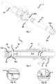
Fig. 1 shows a coupling according to one embodiment wherein the first and second parts are separated. -
Fig. 2 shows a coupling according to one embodiment in a situation where the coupling is in a first lock position wherein purging of the volume between the first and second parts is possible. -
Fig. 2a shows a section of the cold seal in the first lock position. -
Fig. 2b shows a section of the warm seal and its position relative the purge opening in the first lock position. -
Fig. 3 shows a coupling according to one embodiment where the coupling is in a second lock position and transfer of liquefied gas through the coupling is enabled. -
Fig. 3a shows a section of the cold seal in the second lock position. -
Fig. 3b shows a section of the warm seal and its position relative the purge opening in the second lock position. -
Fig. 4 shows a coupling in wherein the emergency release device has been released. -
Fig. 5 shows an embodiment wherein an emergency release device has been released and separation of the first and second coupling parts is completed. -
Fig. 6 shows a detailed view of one embodiment of the valve arrangements. - In the following, a detailed description of the different embodiments of the solution is disclosed under reference to the accompanying drawings. All examples herein should be seen as part of the general description and are therefore possible to combine in any way of general terms. Individual features of the various embodiments and aspects may be combined or exchanged unless such combination or exchange is contradictory to the features of the device or method, as defined by the appended claims.
-
Figure 1 illustrates one embodiment of acoupling 1 wherein thefirst part 11 andsecond part 12 are shown. In the illustration offigure 1 theparts first part 11 is a male part and thesecond part 12 is a female part, wherein the first part is adapted for insertion into the second part. In a typical application, thefirst part 11 is mostly installed on a vehicle, fuel tank, bunker vessel, or any other suitable unit for receiving the liquefied gas. Thesecond part 12 is most likely installed on a fuel station, transport unit, rail car, tank truck, or similar unit for dispatching the liquefied gas. However, as understood other arrangements are also possible within the scope of the solution as described herein. -
Figure 1 further illustrates one embodiment of the solution wherein thecoupling 1 is engaged by align rollers 6b1 to the entrances of a cam curves 6a1. This solution provides distinctive steps to achieve the first and second lock positions, however it should be noted that other solutions are possible as well. - In one embodiment as illustrated in
figure 1 the user pulls the locking device button and push thesecond part 12 being hose unit forward to engage the rollers into the cam curve. Then turn for example 5 to 10 degrees until the locking device will lock into a locking hole. The rollers keepsecond part 12 connected to thefirst part 11 in the first lock position, also called the purge position. A locking pin is locking in the locking hole. To proceed after purge, pull the locking device button and turn for example an additional 20-50 degrees until the rollers stop rotation in the second lock position. In the process the valves slowly open and the locking device will lock into the second locking hole and connection between the liquefied gas conduits is completed. - As further illustrated in the embodiment of
figure 1 , thefirst section 6a of thelocking device 6 comprises a number of cam curves 6a1 and thesecond section 6b of thelocking device 6 comprises a number of rollers 6b1. Each curve 6a1 gets into contact with a roller 6b1 when thesections locking device 6 are in contact with each other. Thesections locking device 6, reach a first lock position. This is a purge position and in one embodiment movement out of the first lock position is prevented by an actuator 6e. If actuated, the actuator 6e allows further movement, either towards disconnection or towards the second lock position. - When the
sections device 6 is in this stop position the actuator 6e of thelocking device 6 in one embodiment comes into an end position and locks thefirst part 11 and thesecond part 12 of thecoupling 1 to each other. The actuator 6e can for example be a pin on thesecond section 6b of thelocking device 6 getting into cooperation with a hole on the first second 6a of thelocking device 6. In other embodiments the movement is restricted in other ways. Thelocking device 6 can have another design and can be forced into the two positions in any way suitable. -
Figure 2 illustrates thecoupling 1 and how it has a double wall vacuum insulated, design to avoid condensation of air at the outside and to reduce thermal bridges in thecoupling 1. Thefirst part 2 of thecoupling 1 comprises avalve arrangement 2b comprising a valve element and a valve guide having a valve seat. Thesecond part 12 of thecoupling 1 also comprises avalve arrangement 3b comprising a valve element and a valve guide having a valve seat. - The first 11 and second 12 parts each has an elongated form and comprises an internal liquefied
gas conduit coupling 1 when theparts first part 11 and thesecond part 12 and to hinder temperature increase of the gas, this is achieved by a volume between the warm 2 and cold 3 seals, seefigure 3 . - Upon insertion of the
first part 11 into thesecond part 12 air, moisture, and other pollutants for cryogenic environments is present around thecoupling 1 and trapped between the first 11 and second 12 parts. This problem is in the prior art often reduced by minimizing dead space between valves in couplings, however this only reduces the problem. To eliminate air and contaminations in the present solution, the coupling is halted at the first lock position before the coupling is fully connected leaving aspace 10a between thevalve arrangements second parts cold seal 3 is not engaged, it is located at a distance from in this embodiment the second part. Thespace 10a is enclosed by the first 11 and second 12 parts and sealed off by the warm seal from the atmosphere. Thus,figure 2 illustrates the first lock position wherein thefirst part 11 and thesecond part 12 are connected, thewarm seal 2 is engaged but thecold seal 3 is not engaged. Further, this state allows for aspace 10a to be formed in the vicinity of theconnection point 10 and between thevalve arrangements - In the first lock position as illustrated in
figure 2 it is thus possible to purge both the volume between thevalve arrangements first part 11 and thesecond part 12. This is in one embodiment achieved through releasing small amounts of liquefied gas via internal liquefiedgas conduit space 10a and passes out around thefirst part 11 and out of the coupling via thepurge opening 4. Thewarm seal 2 prevents liquefied gas from entering the atmosphere and thepurge opening 4 could for example in one embodiment be attached to apurge return pipe 4a, returning the liquefied gas to a distribution system or another suitable storage. -
Figure 2a illustrates a section of thecold seal 3 and shows how it is not engaged to seal between the first and second parts. Instead, a distance exists between the first and second part opening the volume towards thepurge opening 4. -
Figure 2b illustrates a section of thepurge opening 4 and thewarm seal 2 and how they are arranged in relation to each other in the first lock position. -
Figure 3 illustrates one embodiment of thecoupling 1 wherein thefirst part 11 and thesecond part 12 of thecoupling 1 are fully coupled together in the second lock position permitting the liquefied gas to flow from the conduit 2a of thefirst part 11 to theconduit 12a of thesecond part 12 of thecoupling 1. When thefirst part 2 and thesecond part 3 of thecoupling 1 are apart, see for exampleFigure 1 , at least one valve element is urged into the corresponding valve seat preventing the flow of liquefied gas through the respective liquefiedgas conduit - In one embodiment, the
coupling 1 comprises a second warm seal protecting and sealing thecoupling 1 from the atmosphere. The second warm seal further seals the purge opening 4 from the atmosphere in the second lock position wherein thepurge opening 4 is between thewarm seal 2 and the second warm seal. -
Figure 3 further illustrates how the first 11 andsecond parts 12 seal the liquefied gas conduit from the outside by thecold seal 3 and thewarm seal 2. Thewarm seal 2 further seals thepurge opening 4 preventing any leakage even if thecold seal 3 would fail. -
Figure 3a illustrates a section of thecold seal 3 and shows how it is engaged in the second lock position to seal between the first and second parts, compare withfigure 2a . -
Figure 3b illustrates a section of thepurge opening 4 and thewarm seal 2 and how they are arranged in relation to each other in the second lock position, compare withfigure 2b . -
Figure 4 illustrates one embodiment of thecoupling 1 wherein anemergency release device 8 has released the first 11 and second 12 parts from engagement. As shown infigure 4 , theemergency release device 8 separates the first and second parts at a different position than at usual operation, as illustrated parts of thesecond part 12 are still connected to thefirst part 11. This enables that theemergency release device 8 overrides the requirement for thecoupling 1 to halt in the first lock position. The work of theemergency release device 8 result in an emergency shut down that stops the flow of the liquefied gas. The emergency shut down will separate thefirst part 2 of thecoupling 1 from thesecond part 3 of thecoupling 1 to prevent damage of the transfer system. - The
emergency release device 8 comprises elements attached to thesecond part 12 of thecoupling 1. When thecoupling 1 is exposed to determined unwanted load or angles, the elements of theemergency release device 8 is activated. - In one embodiment, when there is a need to disconnect the
coupling 1, a wire attached to a release ring is stretched. Then the release ring is pulled off from theclamp construction 8a that then will loose the grip around theflange 8b and be pushed outwards by a conical part of theflange 8b. The parts of thesecond part 12 of thecoupling 1 will slide off from thefirst part 2, away from thelocking device 6. A stop flange on the outside of thesecond part 12 of thecoupling 1 stops the movement of the release ring along the elongated body of thesecond part 12 of thecoupling 1. Thevalve arrangements cold seal 4 disengages. - The
emergency release device 8 can have another design and can be forced into action in any way suitable. For example, a power emergency release coupling, break studs, break pins, or any other suitable solution. -
Figure 5 illustrates one embodiment of acoupling 1 that has been completely released by theemergency release device 8. -
Figures 6a and 6b illustrate one embodiment ofvalve arrangements figure 6a illustrates thevalve arrangements figure 6b in the first lock position. Each of thevalve arrangements valve valve arrangement valve seat 123 of thesecond part 12 is in the illustrated embodiment spring loaded by thespring 124. Thevalve 121 of the second part is fixed in its position. Thevalve seat 112 of thefirst part 11 is fixed in its position and thevalve 111 of thefirst part 11 is spring loaded by thespring 114. This single poppet valve arrangement helps enable effective purging since no dead space between dual valves is required. - In order to remove air from the conduit so avoid the air contaminating the product to be transferred, it is preferred that the internal liquefied
gas conduit coupling 1. Correspondingly, the internal liquefiedgas conduit - Preferred embodiments of a coupling have been described. It will be appreciated that these may be varied within the scope of the appended claims without deviating from the inventive idea. For example, the warm seal has been described as part of the
first part 11 but it could also be part of thesecond part 12.
Claims (12)
- A coupling (1) comprising a first (11) and second (12) elongated part to be coupled to each other by insertion of the first part (11) into the second part (12), each part (11, 12) comprises an internal liquefied gas conduit (11a, 12a) to be fluidly connected at a connection point (10) for transfer of liquefied gas, preferably liquefied hydrogen or helium, through the coupling (1), one of the first part (11) and the second part comprises a warm seal (2) and the second part (12) comprises a purge opening (4), the coupling (1) further comprising a cold seal (3) arranged to seal a volume between the cold seal (3) and the warm seal (2) from the internal liquefied gas conduits (11a, 12a), characterized in thatthe warm seal is arranged to seal a space between the first and second parts from the atmosphere,the coupling (1) further comprising a locking device (6) with a first and second lock position wherein,- in the first lock position, the first part (11) is partly inserted into the second part (12) such that a space (10a) is formed between the first (11) and second (12) parts, and- the warm seal (2) is engaged such that the purge opening (4) is located between the space (10a) and the warm seal (2) enabling purging of a volume between the first (11) and second (12) parts; and- in the second lock position the first part (11) is fully inserted into the second part (12) forming a fluid connection at the connection point (10).
- The coupling (1) according to claim 1, wherein the warm seal (2) is engaged such that, in the second lock position, the warm seal (2) is located between the purge opening (4) and the connection point (10).
- The coupling (1) according to claim 1 or 2, wherein the distance (L1) between the purge opening (4) and the connection point (10) is longer than the distance (L2) between the warm seal (2) and the connection point (10) when the coupling (1) is fully connected.
- The coupling (1) according to claim 1-3, wherein- in the first lock position the cold seal (3) is disengaged such that a purge path is open between the first (11) and second (12) parts to the purge opening (4), and- in the second lock position the cold seal (3) is engaged creating a closed volume between the cold seal (3) and warm seal (2).
- The coupling (1) according to any one of claims 1-4, wherein the locking device comprises an actuator (6e) preventing the coupling (1) from passing the first lock position without actuation of the actuator (6e).
- The coupling (1) according to any one of claims 1-5, wherein the first (11) and second (12) parts further comprise a valve arrangement (2a, 2b) with at least one valve arranged in the first (11) and second (12) parts, the valves permitting the liquefied gas to flow through the internal liquefied gas conduits (11a, 12a) when the first (11a) and second (12a) liquid conduits are connected, and preventing flow when the first (11a) and second (12a) liquid conduits are apart.
- The coupling (1) according to anyone of claims 1-6, wherein the coupling (1) further comprises an emergency release device (8).
- The coupling (1) according to claim 7, wherein the emergency release device (8) is separate from the locking device such that upon emergency release at least one part of the second part (12) is separated and instead attached to the first part (11) after separation.
- The coupling (1) according to any one of claims 1-8, wherein the first part (11) comprises a first valve arrangement (2b) with a valve (111) comprising a stem and a valve head, the second part (11) comprises a second valve arrangement (3b) with a valve (121) comprising a stem and a valve head, wherein one of said valves (111; 121) is spring-loaded and the other of said valves (111; 121) is arranged in a fixed position in the valve arrangement (2b; 3b).
- A method for purging and connecting a first (11) and second (12) elongated part of a coupling (1) according to any one of claims 1-8, wherein the method comprises the steps:- providing a coupling according to any one of claims 1-8,- inserting the first part (11) into the second part (12),- purging a volume between the first (11) and second (12) part when the locking device (6) is in the first lock position,- further inserting the first part (11) into the second part (12), thus fully connecting the coupling (1), with the locking device (6) in the second lock position.
- The method according to claim 10, the method comprising the additional step of purging the internal liquefied gas conduit (11a, 12a) before transfer of liquefied gas through the coupling (1).
- The method according to claim 10 or 11, the method comprising the additional step of purging the internal liquefied gas conduit (11a, 12a) after transfer of liquefied gas through the coupling (1).
Applications Claiming Priority (2)
| Application Number | Priority Date | Filing Date | Title |
|---|---|---|---|
| SE2151154A SE547208C2 (en) | 2021-09-21 | 2021-09-21 | Coupling with first and second locking position and method for such coupling |
| PCT/SE2022/050827 WO2023048619A1 (en) | 2021-09-21 | 2022-09-20 | Improved insulated coupling |
Publications (3)
| Publication Number | Publication Date |
|---|---|
| EP4232741A1 EP4232741A1 (en) | 2023-08-30 |
| EP4232741B1 true EP4232741B1 (en) | 2024-10-23 |
| EP4232741C0 EP4232741C0 (en) | 2024-10-23 |
Family
ID=83508608
Family Applications (1)
| Application Number | Title | Priority Date | Filing Date |
|---|---|---|---|
| EP22783068.4A Active EP4232741B1 (en) | 2021-09-21 | 2022-09-20 | Improved insulated coupling |
Country Status (8)
| Country | Link |
|---|---|
| EP (1) | EP4232741B1 (en) |
| JP (1) | JP2024532993A (en) |
| KR (1) | KR20240056682A (en) |
| CN (1) | CN117280151A (en) |
| ES (1) | ES2995195T3 (en) |
| PL (1) | PL4232741T3 (en) |
| SE (1) | SE547208C2 (en) |
| WO (1) | WO2023048619A1 (en) |
Families Citing this family (2)
| Publication number | Priority date | Publication date | Assignee | Title |
|---|---|---|---|---|
| SE546778C2 (en) * | 2023-04-20 | 2025-02-18 | Mann Teknik Ab | Device and method for improving a vacuum insulated coupling |
| CN120641685A (en) * | 2023-06-02 | 2025-09-12 | 曼太柯公司 | Apparatus and method for improving vacuum insulated connectors |
Family Cites Families (10)
| Publication number | Priority date | Publication date | Assignee | Title |
|---|---|---|---|---|
| DE2218877A1 (en) * | 1972-04-19 | 1973-10-25 | Kernforschung Gmbh Ges Fuer | LOW TEMPERATURE QUICK COUPLING |
| US5791366A (en) * | 1996-01-16 | 1998-08-11 | Preece Incorporated | Frangible quick disconnect coupling |
| US7052047B1 (en) * | 2002-03-21 | 2006-05-30 | Lockheed Martin Corporation | Detachable high-pressure flow path coupler |
| JP5078219B2 (en) * | 2004-04-26 | 2012-11-21 | 三菱重工業株式会社 | Connector, fluid supply system, connector connection method, and connector separation method |
| DE102005059089A1 (en) * | 2005-12-10 | 2007-06-14 | Nexans | Plug-in coupling for cryogenic pipes |
| EP2884146B8 (en) * | 2013-12-10 | 2017-04-19 | Faster S.p.A. | Multi-connector device for the multiple quick connection of multiple hydraulic, electrical and/or pneumatic lines, with the possibility of individual manual connectors |
| FR3017181B1 (en) * | 2014-02-03 | 2016-08-05 | Gaztransport Et Technigaz | CONNECTION DEVICE FOR CONNECTING TWO FLUID CIRCUITS |
| FR3073919B1 (en) * | 2017-11-23 | 2019-12-20 | Staubli Faverges | MULTI-FITTING PLATE AND PLATE ASSEMBLY INCLUDING SUCH A MULTI-FITTING PLATE |
| ES3054061T3 (en) * | 2019-04-05 | 2026-01-29 | Engineered Controls Int Llc | Coupler having anti-rotation feature |
| US12331884B2 (en) * | 2021-03-04 | 2025-06-17 | Chart Inc. | Cryogenic fluid coupling |
-
2021
- 2021-09-21 SE SE2151154A patent/SE547208C2/en unknown
-
2022
- 2022-09-20 WO PCT/SE2022/050827 patent/WO2023048619A1/en not_active Ceased
- 2022-09-20 KR KR1020237036675A patent/KR20240056682A/en active Pending
- 2022-09-20 CN CN202280030920.0A patent/CN117280151A/en active Pending
- 2022-09-20 PL PL22783068.4T patent/PL4232741T3/en unknown
- 2022-09-20 EP EP22783068.4A patent/EP4232741B1/en active Active
- 2022-09-20 ES ES22783068T patent/ES2995195T3/en active Active
- 2022-09-20 JP JP2023565623A patent/JP2024532993A/en active Pending
Also Published As
| Publication number | Publication date |
|---|---|
| KR20240056682A (en) | 2024-04-30 |
| US20240209977A1 (en) | 2024-06-27 |
| SE547208C2 (en) | 2025-05-27 |
| PL4232741T3 (en) | 2025-02-24 |
| WO2023048619A1 (en) | 2023-03-30 |
| EP4232741C0 (en) | 2024-10-23 |
| CN117280151A (en) | 2023-12-22 |
| ES2995195T3 (en) | 2025-02-07 |
| JP2024532993A (en) | 2024-09-12 |
| SE2151154A1 (en) | 2023-03-22 |
| EP4232741A1 (en) | 2023-08-30 |
Similar Documents
| Publication | Publication Date | Title |
|---|---|---|
| US9416902B2 (en) | Coupling for connecting fluid-conducting lines | |
| WO2023048619A1 (en) | Improved insulated coupling | |
| US10168003B2 (en) | Valve system for an LNG tank | |
| US12601435B2 (en) | Low-emission nozzle and receptacle coupling for cryogenic fluid | |
| CA3103510A1 (en) | Quick-release johnston coupling | |
| US20250003542A1 (en) | Coupling device and method | |
| US12123540B2 (en) | Coupling device and method | |
| US12631285B2 (en) | Insulated coupling | |
| US12215829B2 (en) | Boil-off shielded coupling for hydrogen tank filling | |
| US20230408038A1 (en) | Coupling device and cryogenic refueling arrangement | |
| US20260071708A1 (en) | Coupling for liquified gases | |
| JP2025529158A (en) | Liquefied gas coupler | |
| EP4649256A1 (en) | Device and method for improving a vacuum insulated coupling | |
| WO2023121552A1 (en) | Coupling part for transfer of liquified gas with dual subsequent valves |
Legal Events
| Date | Code | Title | Description |
|---|---|---|---|
| STAA | Information on the status of an ep patent application or granted ep patent |
Free format text: STATUS: UNKNOWN |
|
| STAA | Information on the status of an ep patent application or granted ep patent |
Free format text: STATUS: THE INTERNATIONAL PUBLICATION HAS BEEN MADE |
|
| PUAI | Public reference made under article 153(3) epc to a published international application that has entered the european phase |
Free format text: ORIGINAL CODE: 0009012 |
|
| STAA | Information on the status of an ep patent application or granted ep patent |
Free format text: STATUS: REQUEST FOR EXAMINATION WAS MADE |
|
| 17P | Request for examination filed |
Effective date: 20230526 |
|
| AK | Designated contracting states |
Kind code of ref document: A1 Designated state(s): AL AT BE BG CH CY CZ DE DK EE ES FI FR GB GR HR HU IE IS IT LI LT LU LV MC MK MT NL NO PL PT RO RS SE SI SK SM TR |
|
| GRAP | Despatch of communication of intention to grant a patent |
Free format text: ORIGINAL CODE: EPIDOSNIGR1 |
|
| STAA | Information on the status of an ep patent application or granted ep patent |
Free format text: STATUS: GRANT OF PATENT IS INTENDED |
|
| DAV | Request for validation of the european patent (deleted) | ||
| DAX | Request for extension of the european patent (deleted) | ||
| INTG | Intention to grant announced |
Effective date: 20240513 |
|
| GRAS | Grant fee paid |
Free format text: ORIGINAL CODE: EPIDOSNIGR3 |
|
| GRAA | (expected) grant |
Free format text: ORIGINAL CODE: 0009210 |
|
| STAA | Information on the status of an ep patent application or granted ep patent |
Free format text: STATUS: THE PATENT HAS BEEN GRANTED |
|
| AK | Designated contracting states |
Kind code of ref document: B1 Designated state(s): AL AT BE BG CH CY CZ DE DK EE ES FI FR GB GR HR HU IE IS IT LI LT LU LV MC MK MT NL NO PL PT RO RS SE SI SK SM TR |
|
| REG | Reference to a national code |
Ref country code: GB Ref legal event code: FG4D |
|
| REG | Reference to a national code |
Ref country code: CH Ref legal event code: EP |
|
| REG | Reference to a national code |
Ref country code: DE Ref legal event code: R096 Ref document number: 602022007103 Country of ref document: DE |
|
| REG | Reference to a national code |
Ref country code: IE Ref legal event code: FG4D |
|
| U01 | Request for unitary effect filed |
Effective date: 20241119 |
|
| U07 | Unitary effect registered |
Designated state(s): AT BE BG DE DK EE FI FR IT LT LU LV MT NL PT RO SE SI Effective date: 20241127 |
|
| REG | Reference to a national code |
Ref country code: ES Ref legal event code: FG2A Ref document number: 2995195 Country of ref document: ES Kind code of ref document: T3 Effective date: 20250207 |
|
| PG25 | Lapsed in a contracting state [announced via postgrant information from national office to epo] |
Ref country code: IS Free format text: LAPSE BECAUSE OF FAILURE TO SUBMIT A TRANSLATION OF THE DESCRIPTION OR TO PAY THE FEE WITHIN THE PRESCRIBED TIME-LIMIT Effective date: 20250223 Ref country code: HR Free format text: LAPSE BECAUSE OF FAILURE TO SUBMIT A TRANSLATION OF THE DESCRIPTION OR TO PAY THE FEE WITHIN THE PRESCRIBED TIME-LIMIT Effective date: 20241023 |
|
| PG25 | Lapsed in a contracting state [announced via postgrant information from national office to epo] |
Ref country code: GR Free format text: LAPSE BECAUSE OF FAILURE TO SUBMIT A TRANSLATION OF THE DESCRIPTION OR TO PAY THE FEE WITHIN THE PRESCRIBED TIME-LIMIT Effective date: 20250124 |
|
| PG25 | Lapsed in a contracting state [announced via postgrant information from national office to epo] |
Ref country code: RS Free format text: LAPSE BECAUSE OF FAILURE TO SUBMIT A TRANSLATION OF THE DESCRIPTION OR TO PAY THE FEE WITHIN THE PRESCRIBED TIME-LIMIT Effective date: 20250123 |
|
| PG25 | Lapsed in a contracting state [announced via postgrant information from national office to epo] |
Ref country code: SM Free format text: LAPSE BECAUSE OF FAILURE TO SUBMIT A TRANSLATION OF THE DESCRIPTION OR TO PAY THE FEE WITHIN THE PRESCRIBED TIME-LIMIT Effective date: 20241023 |
|
| PG25 | Lapsed in a contracting state [announced via postgrant information from national office to epo] |
Ref country code: SK Free format text: LAPSE BECAUSE OF FAILURE TO SUBMIT A TRANSLATION OF THE DESCRIPTION OR TO PAY THE FEE WITHIN THE PRESCRIBED TIME-LIMIT Effective date: 20241023 |
|
| PG25 | Lapsed in a contracting state [announced via postgrant information from national office to epo] |
Ref country code: CZ Free format text: LAPSE BECAUSE OF FAILURE TO SUBMIT A TRANSLATION OF THE DESCRIPTION OR TO PAY THE FEE WITHIN THE PRESCRIBED TIME-LIMIT Effective date: 20241023 |
|
| PLBE | No opposition filed within time limit |
Free format text: ORIGINAL CODE: 0009261 |
|
| STAA | Information on the status of an ep patent application or granted ep patent |
Free format text: STATUS: NO OPPOSITION FILED WITHIN TIME LIMIT |
|
| 26N | No opposition filed |
Effective date: 20250724 |
|
| PGFP | Annual fee paid to national office [announced via postgrant information from national office to epo] |
Ref country code: NO Payment date: 20250922 Year of fee payment: 4 |
|
| PGFP | Annual fee paid to national office [announced via postgrant information from national office to epo] |
Ref country code: PL Payment date: 20250826 Year of fee payment: 4 |
|
| U20 | Renewal fee for the european patent with unitary effect paid |
Year of fee payment: 4 Effective date: 20250916 |
|
| PGFP | Annual fee paid to national office [announced via postgrant information from national office to epo] |
Ref country code: ES Payment date: 20251006 Year of fee payment: 4 |
|
| REG | Reference to a national code |
Ref country code: CH Ref legal event code: H13 Free format text: ST27 STATUS EVENT CODE: U-0-0-H10-H13 (AS PROVIDED BY THE NATIONAL OFFICE) Effective date: 20260504 |