EP4232360B1 - System and method for providing electrical power to a tethered aerial vehicle - Google Patents
System and method for providing electrical power to a tethered aerial vehicle Download PDFInfo
- Publication number
- EP4232360B1 EP4232360B1 EP21901506.2A EP21901506A EP4232360B1 EP 4232360 B1 EP4232360 B1 EP 4232360B1 EP 21901506 A EP21901506 A EP 21901506A EP 4232360 B1 EP4232360 B1 EP 4232360B1
- Authority
- EP
- European Patent Office
- Prior art keywords
- aerial vehicle
- amperage
- buck converter
- voltage
- leds
- Prior art date
- Legal status (The legal status is an assumption and is not a legal conclusion. Google has not performed a legal analysis and makes no representation as to the accuracy of the status listed.)
- Active
Links
Images


Classifications
-
- B—PERFORMING OPERATIONS; TRANSPORTING
- B64—AIRCRAFT; AVIATION; COSMONAUTICS
- B64C—AEROPLANES; HELICOPTERS
- B64C39/00—Aircraft not otherwise provided for
- B64C39/02—Aircraft not otherwise provided for characterised by special use
- B64C39/022—Tethered aircraft
-
- B—PERFORMING OPERATIONS; TRANSPORTING
- B64—AIRCRAFT; AVIATION; COSMONAUTICS
- B64D—EQUIPMENT FOR FITTING IN OR TO AIRCRAFT; FLIGHT SUITS; PARACHUTES; ARRANGEMENT OR MOUNTING OF POWER PLANTS OR PROPULSION TRANSMISSIONS IN AIRCRAFT
- B64D47/00—Equipment not otherwise provided for
- B64D47/02—Arrangements or adaptations of signal or lighting devices
-
- B—PERFORMING OPERATIONS; TRANSPORTING
- B64—AIRCRAFT; AVIATION; COSMONAUTICS
- B64F—GROUND OR AIRCRAFT-CARRIER-DECK INSTALLATIONS SPECIALLY ADAPTED FOR USE IN CONNECTION WITH AIRCRAFT; DESIGNING, MANUFACTURING, ASSEMBLING, CLEANING, MAINTAINING OR REPAIRING AIRCRAFT, NOT OTHERWISE PROVIDED FOR; HANDLING, TRANSPORTING, TESTING OR INSPECTING AIRCRAFT COMPONENTS, NOT OTHERWISE PROVIDED FOR
- B64F3/00—Ground installations specially adapted for captive aircraft
- B64F3/02—Ground installations specially adapted for captive aircraft with means for supplying electricity to aircraft during flight
-
- B—PERFORMING OPERATIONS; TRANSPORTING
- B64—AIRCRAFT; AVIATION; COSMONAUTICS
- B64U—UNMANNED AERIAL VEHICLES [UAV]; EQUIPMENT THEREFOR
- B64U10/00—Type of UAV
- B64U10/60—Tethered aircraft
-
- H—ELECTRICITY
- H02—GENERATION; CONVERSION OR DISTRIBUTION OF ELECTRIC POWER
- H02J—ELECTRIC POWER NETWORKS; CIRCUIT ARRANGEMENTS OR SYSTEMS FOR SUPPLYING OR DISTRIBUTING ELECTRIC POWER; SYSTEMS FOR STORING ELECTRIC ENERGY
- H02J1/00—Circuit arrangements for DC mains or DC distribution networks
- H02J1/08—Three-wire DC power distribution systems; Systems having more than three wires
-
- B—PERFORMING OPERATIONS; TRANSPORTING
- B64—AIRCRAFT; AVIATION; COSMONAUTICS
- B64C—AEROPLANES; HELICOPTERS
- B64C39/00—Aircraft not otherwise provided for
- B64C39/02—Aircraft not otherwise provided for characterised by special use
- B64C39/024—Aircraft not otherwise provided for characterised by special use of the remote controlled vehicle type, i.e. RPV
-
- B—PERFORMING OPERATIONS; TRANSPORTING
- B64—AIRCRAFT; AVIATION; COSMONAUTICS
- B64D—EQUIPMENT FOR FITTING IN OR TO AIRCRAFT; FLIGHT SUITS; PARACHUTES; ARRANGEMENT OR MOUNTING OF POWER PLANTS OR PROPULSION TRANSMISSIONS IN AIRCRAFT
- B64D2203/00—Aircraft or airfield lights using LEDs
-
- B—PERFORMING OPERATIONS; TRANSPORTING
- B64—AIRCRAFT; AVIATION; COSMONAUTICS
- B64U—UNMANNED AERIAL VEHICLES [UAV]; EQUIPMENT THEREFOR
- B64U10/00—Type of UAV
- B64U10/10—Rotorcrafts
- B64U10/13—Flying platforms
-
- B—PERFORMING OPERATIONS; TRANSPORTING
- B64—AIRCRAFT; AVIATION; COSMONAUTICS
- B64U—UNMANNED AERIAL VEHICLES [UAV]; EQUIPMENT THEREFOR
- B64U20/00—Constructional aspects of UAVs
- B64U20/80—Arrangement of on-board electronics, e.g. avionics systems or wiring
-
- B—PERFORMING OPERATIONS; TRANSPORTING
- B64—AIRCRAFT; AVIATION; COSMONAUTICS
- B64U—UNMANNED AERIAL VEHICLES [UAV]; EQUIPMENT THEREFOR
- B64U2201/00—UAVs characterised by their flight controls
- B64U2201/20—Remote controls
- B64U2201/202—Remote controls using tethers for connecting to ground station
-
- B—PERFORMING OPERATIONS; TRANSPORTING
- B64—AIRCRAFT; AVIATION; COSMONAUTICS
- B64U—UNMANNED AERIAL VEHICLES [UAV]; EQUIPMENT THEREFOR
- B64U50/00—Propulsion; Power supply
- B64U50/30—Supply or distribution of electrical power
-
- H—ELECTRICITY
- H02—GENERATION; CONVERSION OR DISTRIBUTION OF ELECTRIC POWER
- H02J—ELECTRIC POWER NETWORKS; CIRCUIT ARRANGEMENTS OR SYSTEMS FOR SUPPLYING OR DISTRIBUTING ELECTRIC POWER; SYSTEMS FOR STORING ELECTRIC ENERGY
- H02J2105/00—Networks for supplying or distributing electric power characterised by their spatial reach or by the load
- H02J2105/30—Networks for supplying or distributing electric power characterised by their spatial reach or by the load the load networks being external to vehicles, i.e. exchanging power with vehicles
- H02J2105/32—Networks for supplying or distributing electric power characterised by their spatial reach or by the load the load networks being external to vehicles, i.e. exchanging power with vehicles for aircrafts
Definitions
- the present disclosure is generally related to electrical power systems and more particularly is related to a system and method for providing electrical power to a tethered aerial vehicle.
- UASs unmanned aerial systems
- UASs unmanned aerial systems
- UASs unmanned aerial systems
- UASs are commonly used to conduct surveillance, deliver items, and perform operations.
- UASs or drones are widely used in recreation, sport, and various industries to perform tasks.
- UASs have been outfitted with electronic devices, such as cameras, thereby allowing users to take aerial photographs.
- UASs have been equipped with lights in order to provide aerial or elevated overhead lighting of an outdoor space. These UASs with lights can be used to provide fast and temporary lighting for an outside space, in place of more traditional outdoor lighting units, such as permanent light poles or trailer-mounted lighting units which have temporary lights that are raised to an elevated position.
- High power wide area lighting from these UASs typically greater than 20,000 lumens delivered from higher than 25 feet, enables many activities to occur outdoors at night which would not otherwise be possible, including, for example, construction, sports, and entertainment.
- UAS and lighting technology it is now possible for a UAS to lift high-powered lighting devices to altitudes at and above that of conventional light poles.
- most implementations of high power lighting on UASs emit less than 12,000 lumens and are limited to less than an hour of lighted flight.
- a UAS may be equipped with a tether which electrically connects the UAS with a ground-based power supply, such as a battery, generator, or a traditional hardwired power from the grid.
- a ground-based power supply such as a battery, generator, or a traditional hardwired power from the grid.
- the tether typically includes a wire having conductors which may be enveloped within a sheathing or light-weight rope. Electrical power may be delivered from the ground-based power supply, through the tether, and to both the UAS's propulsion or flight control systems and the lighting system carried by the UAS.
- the subject disclosure is directed to an aerial vehicle electrical power system, and related methods, apparatuses, and technologies.
- the aerial vehicle electrical power system may be used to improve the electrical performance of a tethered vehicle, such as a UAS, a manned aerial system, a drone, or any other type of vehicle which operates with a tether.
- the aerial vehicle electrical power system may allow for proper power distribution and control of electrical power supplied through the tether to both the tethered vehicle itself, e.g., the propulsion or control systems of the vehicle, and to lights, cameras, or other devices which are carried by the aerial vehicle.
- lights and specifically light-emitting diodes (LEDs), are the exemplary electronic device carried by the aerial vehicle described herein, but any other type of electronic device carriable by the aerial vehicle is considered within the scope of this disclosure.
- the use of the aerial vehicle electrical power system helps minimize, prevent, and smooth electrical voltage variances within the aerial vehicle or the LEDs, irrespective of varying power draw of the DC buck converter as it powers the UAS and/or other accessories.
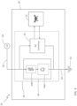
- FIG. 1 is a schematic diagram of an aerial vehicle electrical power system 10, in accordance with a first exemplary embodiment of the present disclosure.
- FIG. 2 is a diagrammatical illustration of a tethered aerial vehicle using the aerial vehicle electrical power system of FIG. 1 , in accordance with the first exemplary embodiment of the present disclosure.
- the aerial vehicle electrical power system 10 which may be referred to herein simply as 'system 10' includes an aerial vehicle 20, which may include any type of aerial vehicle, such as manned vehicle, an unmanned aerial system (UAS), a drone, or a similar vehicle.
- UAS unmanned aerial system
- a plurality of light-emitting diodes (LEDs) 30 are carried by the aerial vehicle 20, such as by mounting one or more LED arrays or similar lighting fixtures to the frame of the aerial vehicle 20.
- the LEDs 30 are capable of illuminating a quantity of light 32 upon a surface of the ground 12, or another location.
- the LEDs are high-powered LEDs capable of emitting substantially 20,000 lumens or greater.
- At least one electrical circuit 40 is carried by the aerial vehicle 20, and often, the electrical circuit 40 may be integrated with the electrical system of the aerial vehicle 20 itself, such that it is in communication with the propulsion and control system 22 of the aerial vehicle 20.
- the electrical circuit 40 has a DC buck converter 42 which is connected electrically in series with at least a portion of the plurality of LEDs 30. It is noted that the LEDs 30 may be in series before or after the DC buck converter 42.
- the DC buck converter 42 has the characteristic that it outputs lower voltage relative to the input voltage, and outputs higher amperage relative to the input amperage.
- the DC buck converter may include one or more converters depending on the design of the system 10.
- a single DC buck converter 42 or multiple DC buck converters may be used in parallel and/or in series.
- the amperage boost converter (discussed relative to FIG. 3 ) contains LEDs in series
- the DC buck converter 42 inputs may be configured in series by using the LEDs of amperage boost converter in series as voltage dividers.
- a tether 50 is connected between the aerial vehicle 20 and a positive terminal 60 and the negative terminal 62 of a power source 64 positioned on the ground surface 12 or similar location remote from the aerial vehicle.
- the power source 64 may be located on the Earth's surface, on a land or water based vehicle, on a different UAS, or in any other location which is remote from the aerial vehicle 20 . Electrical power for powering the LEDs 30 and the aerial vehicle 20 is transmitted to the aerial vehicle 20 and at least a portion of the plurality of LEDs 30 through the tether 50.
- Power is supplied to the aerial vehicle 20 and the LEDs 30 using the tether 50 which is formed from a two-conductor wire 52, having a positive conductor 52A and a negative (or ground) conductor 52B, which are connected to the positive terminal of the power source 64 and the negative terminal 62 of the power source 64.
- the power source 64 may vary, in one example, it is a DC power source and a boost converter which maintains a constant voltage.
- the added weight from the additional wires, as compared to a two-conductor wire tether 50, would require more power to the aerial vehicle 20, and likely an aerial vehicle 20 with a greater lift capacity.
- the use of a two-conductor wire enables the minimum possible tether weight to be achieved, which in turn, lowers the overall weight of the aerial vehicle 20, thereby reducing the power required by the aerial vehicle 20. In some instances, this means that potentially, a smaller and less expensive aerial vehicle 20 may be used.
- the use of the two-conductor wire as the tether 50, or as a component of the tether 50 ensures the tether 50 is light enough to not add unneeded weight to the payload of the aerial vehicle 20.
- the system 10 minimizes the probability that the operation of the aerial vehicle 20 and the LEDs 30 is interrupted by power variances through the tether 50 and to the aerial vehicle 20. For instance, during certain aspects of flight of the aerial vehicle 20, such as upon initial start-up and takeoff, the aerial vehicle 20 can draw substantially more power than during constant flight. Similarly, certain maneuvers of the aerial vehicle 20 will cause it to draw more power than when it is stationary.
- the system 10 can regulate these power variances through the tether 50 and from the aerial vehicle 20 to minimize the variance of light output from the LEDs 30.
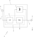
- FIG. 3 is a schematic diagram showing a variation of the aerial vehicle electrical power system 10 of FIG. 1 , in accordance with the first exemplary embodiment of the present disclosure.
- FIG. 3 illustrates an example of the system 10 which uses an amperage boost regulator 44, which is a resistance device, such as a diode, which increases in resistance as voltage across amperage boost regulator 44 decreases.
- the amperage boost regulator 44 may be used in parallel with a load which has a high variance of amperage requirements, such as the DC buck converter 42 as it powers the aerial vehicle 20.
- the amperage boost regulator 44 acts by decreasing amperage and voltage variances across the parallel circuit formed between the amperage boost regulator 44 and the DC buck converter 42, which may be caused by amperage variances from the DC buck converter 42 and resistance between the electrical power source 64 and the parallel circuit.
- a DC buck converter 42 may have a input voltage range, e.g., maximum input voltage and minimum input voltage, with which it must be operated.
- the parallel amperage boost regulator 44 pulls greater amperage which, due planned resistance in the system 10 including the tether 50, limits voltage increases and allows the DC buck converter's 42 input voltage to remain below the input maximum.
- the amperage boost regulator 44 includes at least one or more LEDs 44A or a resistance device 44B, but may, in some situations, include both.
- the LEDs 44A may be characterized as primary LEDs while the LEDs 30 are secondary or optional LEDs which can provide additional lighting.
- the LEDs 44A and the resistance device 44B are in parallel with the DC buck converter 42.
- the DC buck converter 42 may include various types of step-down converters or similar devices, such as, for instance, a buck converter which is a DC-to-DC power converter which outputs lower voltage relative to the input voltage, and output higher amperage relative to the input amperage.
- the voltage across the power source 64 is above the maximum voltage allowed by the DC buck converter 42.
- the resistance of the amperage boost regulator 44 is configured to draw sufficient amperage such that the resistance within the tether wire 50 and the LEDs 30 in series with the DC buck converter 42 reduces the voltage to the DC buck converter 42 to be below the maximum voltage allowed.
- amperage boost regulator 44 allows for lower voltage to be used in a similar diameter conductor within the tether 50. Varying amperage causes voltages across a wire to vary. The amperage boost regulator 44, which minimizes the amperage variation, also minimizes voltage variation. As a result, a smaller diameter-and lower weight-conductor may be used, versus a configuration where amperage variations are not minimized. Alternatively, a longer tether 50 may be used without increasing the conductor wire diameter. If using a smaller diameter conductor wire, energy savings and performance benefits of a lowered total wire weight can be balanced against any lost electrical efficiencies due to increased wire resistance, as may be determined by the individual design of the system 10.
- the power source 64 is integrated into a ground base power station located on the ground surface 12.
- the power source 64 supplies constant voltage through a conductor in the tether 50 to the electrical circuit 40, which is attached to or integrated within the aerial vehicle 20.
- a DC buck converter 42 typically operates only within a specified narrow range of voltages, for instance, between 30 to 45 volts.
- the resistance range of the amperage boost regulator 44 is configured such that it draws sufficient amperage across the LEDs 30, connected in series, and the tether 50 with conductors to reduce the voltage at the DC buck converter 42 to be within the DC buck converter's 42 required input voltage range.
- the DC buck converter 42 draws more amperage and then the input voltage to the DC buck converter 42 decreases, due to wire resistance. As this happens, the amperage boost regulator 44 receives lower voltage, increases resistance, and decreases its load (amperage used). With decreasing voltage, the DC buck converter 42 effectively maintains power priority over the amperage boost regulator 44, thereby ensuring the propulsion and control system 22 of the aerial vehicle 20 are not unduly limited.
- V Base Power Supply V Drop Tether + V Drop Optional series LED + V Required for DC converter
- V Base Power Supply is the based voltage from the power supply
- V Drop Tether is the voltage drop across the tether 5
- V Drop Optional series LED is the voltage drop across the LEDs 30 positioned in series with the DC buck converter 42
- V Required for DC converter is the voltage required for the DC buck converter 42.
- Voltage ranges based on expected amperage variances may also be considered in the calculations.
- This example of the system 10 assumes that the voltage from the base station power supply will be set according to this calculation and that the supplied source voltage across the power source 64 terminals 60, 62, to which the tether 50 is connected, will be constant.
- the following aspects of the system 10 may be considered for balancing the system 10:
- the system 10 described relative to FIG. 3 may include variations in the electrical circuit 40.
- the LEDs 30 in series may not be present, but the amperage boost regulator 44 may contain one or more LEDs 44A. This variation may be used when additional light is not required.
- the LEDs 30 in series may not be present, and the voltage across the power source 64 is below the maximum input voltage required by the DC buck converter 42.
- the amperage boost regulator 44 may contain one or more LEDs 44A. The advantage of this simplified configuration is that it enables switched LED dimming to be used, such as by quickly turning the LEDs 44A in the amperage boost regulator 44 on and off.
- amperage boost regulator 44 would not be used to lower voltage to the DC buck converter 42. Additionally, it is optionally possible to use a dimmer with the amperage boost regulator 44 to cause the amperage boost regulator 44 resistance to increase, such as by using a variable resistor or pulse width modulation (PWM). With greater resistance, less amperage will flow through the LEDs 44A.
- PWM pulse width modulation
- a working example of the system 10 uses the amperage boost regulator 44 configuration of FIG. 3 with the diagrammatical illustration of FIG. 2 .
- a prototype system 10 included an aerial vehicle 20 flying at height (H) of 40 feet above the ground surface 12.
- the prototype of the system 10 uses 4 LEDs, where two LEDs are in a parallel load configuration, e.g. , 44A, and two additional LEDs 30 are in series with the other two LEDs 44A.
- the LEDs 30, 44A draw approximately 200 watts and provide over 20,000 lumens of light.
- the power supply of the ground power base system provides 100 volts through a 20 gauge wire to the LEDs 30 in series with the amperage boost regulator 44 and the DC buck converter 42.
- the amperage pulled by the amperage boost regulator 44 reduced the voltage to the DC buck converter 42 such that it is maintained within the DC buck converter's acceptable input voltage range.
- the LED lights also turn on, even though the drone is off, due to amperes being pulled by the amperage boost regulator 44 through the LEDs 30 in series.
- the DC buck converter 42 then receives the voltage with the required input range, powers on, and then provides power to the aerial vehicle 20, namely, the propulsion and control system 22 of the aerial vehicle 20.
- the aerial vehicle 20 and DC buck converter 42 pull slightly more amperage through the LEDs 30 in series, and as a result, the LEDs 30 brighten.
- the LEDs 44A in the amperage boost regulator 44 dim slightly as amperage decreases due to the voltage decrease and resistance increase.
- the amperage boost regulator 44 uses a resistor 44B in series with two LEDs 44A (in parallel). As is a common use, resistors 44B may help to ensure that the maximum amperage of the LEDs is not exceeded.
- the system 10 may provide substantial benefits to the field of power systems for UASs, and in particular, those UASs which utilize lights or other electronic equipment onboard.
- the system 10 allows the UAS to be more weight efficient than other methods of powering onboard electronics, which power the electronics and the UAS itself in a manner which is not in series. Conventional methods require a heavier converter, a heavier tether, or often both.
- the system eliminates the need for a DC buck converter to power the LEDs and it eliminates the need for additional wires in the tether to power the LEDs separately. The result is an increase in light output as the UAS ascends higher (as the UAS ascends, it lifts more tether thereby pulling more amps).
- FIGS. 1-3 describe the system 10 in accordance with the first exemplary embodiment
- FIGS. 4-6 describe variations of the system 10 in accordance with other embodiments. Any of the features, components, or functions of the system 10 described relative to FIGS. 1-3 may be used with any embodiment of this disclosure, but the same is not reproduced relative to FIGS. 4-6 for clarity in disclosure.
- FIG. 4 is a schematic diagram showing a variation of the aerial vehicle electrical power system 10 of FIG. 1 , in accordance with a second exemplary embodiment of the present disclosure.
- FIG. 4 illustrates a physical configuration which is shared by the amperage boost regulator 44 and a simple parallel configuration.
- the power source 64 is located on the ground surface. Electricity travels from the power source 64 through the tethered wire 50 to power the parallel load of the amperage boost regulator 44 and the DC buck converter 42.
- the DC buck converter 42 lowers the voltage to what is typically required by an aerial vehicle. In terms of flight performance, a very important advantage of paralleling the DC buck converter 42 with the LEDs 44A is that the DC buck converter 42 takes power priority if insufficient amperage is available to fully power both.
- the voltage across the power source 64 is above the maximum voltage allowed across the inputs of the DC buck converter 42.
- the amperage load created by the parallel load of the amperage boost regulator 44 is configured to be high enough such that the resistance within the tether 50 lowers the voltage to the DC buck converter 42 to be below the maximum voltage of the DC buck converter 42.
- the amperage boost regulator 44 may include a resistor 44B, an LED 44A, or both.
- the voltage provided by the power source 64 is below the maximum voltage allowed by the DC buck converter 42.
- the load at the amperage boost regulator 44 contains at least one LED 44A.
- the parallel load power state e.g., on or off, does not impact the DC buck converter 42.
- the gauge of the tether wire 50 is configured to be low enough such that voltage to the DC buck converter 42 will be above the minimum when both the parallel load of the amperage boost regulator 44 and the aerial vehicle 20 are at full power.
- FIG. 5 is a schematic diagram showing a variation of the aerial vehicle electrical power system 10 of FIG. 1 , in accordance with a fourth exemplary embodiment of the present disclosure.
- FIG. 5 is directed to a simplified system 10 where the amperage boost regulator (44 in FIG. 3 ) is replaced with a resistance device 44B.
- the resistance device 44B may have the purpose of drawing sufficient amperage and voltage to activate the primary LEDs 30 and to allow the required voltage to pass to the propulsion and control system 22 of the aerial vehicle 20 even if the propulsion and control system 22 does not draw amperage.
- LEDs 30 may turn off when sufficient forward voltage is not provided.
- a resistor 44B, or similar load, between the LEDs 30 and the negative terminal 62, which is shared by the aerial vehicle 20 and the LEDs 30, enables the LEDs 30 to pass sufficient voltage and amperage to enable the propulsion and control system 22 to operate.
- the resistance device 44B may also regulate amperage across the tether 50.
- the load which is placed in parallel with the propulsion and control system 22, allows the LEDs 30 to draw a minimum amount of amperes through the tether 50 when the aerial vehicle 20 is off or at low power.
- both the tether 50 and the LEDs 30 use more voltage (due to resistance) and decrease the voltage to the parallel propulsion and control system 22 with the resistance device 44B.
- voltage to the resistance device 44B decreases, the amperage required by it also decreases.
- the propulsion and control system 22, which may use a DC converter, may continue to operate efficiently within the lower voltage range.
- an advantage of using the resistance device 44B may be to reduce the range or variance of amperages experienced across the tether 50, which may assist with reducing voltage variances across the tether 50, which may be caused by resistance along the wire or conductor within the tether 50. By reducing variances, potentially longer tethers 50 may be used without increasing the diameter of the conductor therein.
- FIG. 6 is a flowchart 100 illustrating a method for powering an aerial vehicle carrying lights, in accordance with the first exemplary embodiment of the present disclosure.
- any process descriptions or blocks in flow charts should be understood as representing modules, segments, portions of code, or steps that include one or more instructions for implementing specific logical functions in the process, and alternate implementations are included within the scope of the present disclosure in which functions may be executed out of order from that shown or discussed, including substantially concurrently or in reverse order, depending on the functionality involved, as would be understood by those reasonably skilled in the art of the present disclosure.
- an aerial vehicle has a plurality of light-emitting diodes (LEDs) mounted thereto.
- a tether is connected between the aerial vehicle and a power source located remote from the aerial vehicle (block 104).
- a quantity of electrical power is transmitted through the tether, wherein the quantity of electrical power is transmitted through at least one electrical circuit carried by the aerial vehicle, wherein the at least one electrical circuit has a DC buck converter electrically in series with at least a portion of the plurality of LEDs (block 106). Any number of additional steps, functions, processes, or variants thereof may be included in the method, including any disclosed relative to any other figure of this disclosure.
Landscapes
- Engineering & Computer Science (AREA)
- Aviation & Aerospace Engineering (AREA)
- Mechanical Engineering (AREA)
- Remote Sensing (AREA)
- Power Engineering (AREA)
- Microelectronics & Electronic Packaging (AREA)
- Chemical & Material Sciences (AREA)
- Combustion & Propulsion (AREA)
- Circuit Arrangement For Electric Light Sources In General (AREA)
- Lighting Device Outwards From Vehicle And Optical Signal (AREA)
- Forklifts And Lifting Vehicles (AREA)
- Dc-Dc Converters (AREA)
Description
- The present disclosure is generally related to electrical power systems and more particularly is related to a system and method for providing electrical power to a tethered aerial vehicle.
- Aerial systems, and in particular, unmanned aerial systems (UASs) are becoming increasingly prevalent. In the military, both manned aerial systems and UASs are commonly used to conduct surveillance, deliver items, and perform operations. Outside of the military, UASs or drones are widely used in recreation, sport, and various industries to perform tasks. In recent times, UASs have been outfitted with electronic devices, such as cameras, thereby allowing users to take aerial photographs.
- In a similar manner, UASs have been equipped with lights in order to provide aerial or elevated overhead lighting of an outdoor space. These UASs with lights can be used to provide fast and temporary lighting for an outside space, in place of more traditional outdoor lighting units, such as permanent light poles or trailer-mounted lighting units which have temporary lights that are raised to an elevated position. High power wide area lighting from these UASs, typically greater than 20,000 lumens delivered from higher than 25 feet, enables many activities to occur outdoors at night which would not otherwise be possible, including, for example, construction, sports, and entertainment. Additionally, with the advancement of both UAS and lighting technology, it is now possible for a UAS to lift high-powered lighting devices to altitudes at and above that of conventional light poles. Currently, due to the power limitations of the onboard battery of the UAS, most implementations of high power lighting on UASs emit less than 12,000 lumens and are limited to less than an hour of lighted flight.
- To provide temporary outdoor lighting for longer periods of time, or to provide brighter lighting, a UAS may be equipped with a tether which electrically connects the UAS with a ground-based power supply, such as a battery, generator, or a traditional hardwired power from the grid. Using a tethered UAS, it is now possible to provide continuous power to the UAS. The tether typically includes a wire having conductors which may be enveloped within a sheathing or light-weight rope. Electrical power may be delivered from the ground-based power supply, through the tether, and to both the UAS's propulsion or flight control systems and the lighting system carried by the UAS. However, it can often be difficult to deliver the electrical power to both the UAS and high powered LEDs through the tether in a weight efficient manner. Lowering the payload weight would enable smaller, lighter, more portable, and less power hungry UASs to be used for lighting.
- Current tethered UASs are designed to power a number of different payloads. Typically, higher voltage DC delivered through the tether from the ground-based power source is down converted by an onboard DC converter to a lower voltage for use by the drone and accessories including high power lighting. If more power for the light accessory is required, then a larger, and heavier, DC converter and heat sink will also be required. Thus, to carry the extra weight, the UAS size must increase as the power requirement for lighting increases. As the overall weight increases, the required power from the ground-based power system also increases.
US 2017/346387 A1 is an example of prior art document . - Thus, a heretofore unaddressed need exists in the industry to address the aforementioned deficiencies and inadequacies.
- Embodiments of the present disclosure are disclosed in the appended claims.
- Other systems, methods, features, and advantages of the present disclosure will be or become apparent to one with skill in the art upon examination of the following drawings and detailed description. It is intended that all such additional systems, methods, features, and advantages be included within this description, be within the scope of the present disclosure, and be protected by the accompanying claims.
- Many aspects of the disclosure can be better understood with reference to the following drawings. The components in the drawings are not necessarily to scale, emphasis instead being placed upon clearly illustrating the principles of the present disclosure. Moreover, in the drawings, like reference numerals designate corresponding parts throughout the several views.
-
FIG. 1 is a schematic diagram of an aerial vehicle electrical power system, in accordance with a first exemplary embodiment of the present disclosure. -
FIG. 2 is a diagrammatical illustration of a tethered aerial vehicle using the aerial vehicle electrical power system ofFIG. 1 , in accordance with the first exemplary embodiment of the present disclosure. -
FIG. 3 is a schematic diagram showing a variation of the aerial vehicle electrical power system ofFIG. 1 , in accordance with the first exemplary embodiment of the present disclosure. -
FIG. 4 is a schematic diagram showing a variation of the aerial vehicle electrical power system ofFIG. 1 , in accordance with a second exemplary embodiment of the present disclosure. -
FIG. 5 is a schematic diagram showing a variation of the aerial vehicle electrical power system ofFIG. 1 , in accordance with a fourth exemplary embodiment of the present disclosure. -
FIG. 6 is a flowchart illustrating a method for powering an aerial vehicle carrying lights, in accordance with the first exemplary embodiment of the present disclosure. - To improve over the shortcomings described in the Background, the subject disclosure is directed to an aerial vehicle electrical power system, and related methods, apparatuses, and technologies. As described herein, the aerial vehicle electrical power system may be used to improve the electrical performance of a tethered vehicle, such as a UAS, a manned aerial system, a drone, or any other type of vehicle which operates with a tether. In particular, the aerial vehicle electrical power system may allow for proper power distribution and control of electrical power supplied through the tether to both the tethered vehicle itself, e.g., the propulsion or control systems of the vehicle, and to lights, cameras, or other devices which are carried by the aerial vehicle. For clarity in disclosure, lights, and specifically light-emitting diodes (LEDs), are the exemplary electronic device carried by the aerial vehicle described herein, but any other type of electronic device carriable by the aerial vehicle is considered within the scope of this disclosure. The use of the aerial vehicle electrical power system helps minimize, prevent, and smooth electrical voltage variances within the aerial vehicle or the LEDs, irrespective of varying power draw of the DC buck converter as it powers the UAS and/or other accessories.
-
FIG. 1 is a schematic diagram of an aerial vehicleelectrical power system 10, in accordance with a first exemplary embodiment of the present disclosure.FIG. 2 is a diagrammatical illustration of a tethered aerial vehicle using the aerial vehicle electrical power system ofFIG. 1 , in accordance with the first exemplary embodiment of the present disclosure. With reference toFIGS. 1-2 , the aerial vehicleelectrical power system 10, which may be referred to herein simply as 'system 10' includes anaerial vehicle 20, which may include any type of aerial vehicle, such as manned vehicle, an unmanned aerial system (UAS), a drone, or a similar vehicle. A plurality of light-emitting diodes (LEDs) 30 are carried by theaerial vehicle 20, such as by mounting one or more LED arrays or similar lighting fixtures to the frame of theaerial vehicle 20. TheLEDs 30 are capable of illuminating a quantity oflight 32 upon a surface of theground 12, or another location. In one example, the LEDs are high-powered LEDs capable of emitting substantially 20,000 lumens or greater. - At least one
electrical circuit 40 is carried by theaerial vehicle 20, and often, theelectrical circuit 40 may be integrated with the electrical system of theaerial vehicle 20 itself, such that it is in communication with the propulsion andcontrol system 22 of theaerial vehicle 20. As shown inFIG. 1 , theelectrical circuit 40 has aDC buck converter 42 which is connected electrically in series with at least a portion of the plurality ofLEDs 30. It is noted that theLEDs 30 may be in series before or after theDC buck converter 42. TheDC buck converter 42 has the characteristic that it outputs lower voltage relative to the input voltage, and outputs higher amperage relative to the input amperage. The DC buck converter may include one or more converters depending on the design of thesystem 10. For example, a singleDC buck converter 42 or multiple DC buck converters (not shown ) may be used in parallel and/or in series. In one situation, if the amperage boost converter (discussed relative toFIG. 3 ) contains LEDs in series, then theDC buck converter 42 inputs may be configured in series by using the LEDs of amperage boost converter in series as voltage dividers. - A
tether 50 is connected between theaerial vehicle 20 and apositive terminal 60 and thenegative terminal 62 of apower source 64 positioned on theground surface 12 or similar location remote from the aerial vehicle. Within the scope of this disclosure, thepower source 64 may be located on the Earth's surface, on a land or water based vehicle, on a different UAS, or in any other location which is remote from theaerial vehicle 20 . Electrical power for powering theLEDs 30 and theaerial vehicle 20 is transmitted to theaerial vehicle 20 and at least a portion of the plurality ofLEDs 30 through thetether 50. Power is supplied to theaerial vehicle 20 and theLEDs 30 using thetether 50 which is formed from a two-conductor wire 52, having apositive conductor 52A and a negative (or ground) conductor 52B, which are connected to the positive terminal of thepower source 64 and thenegative terminal 62 of thepower source 64. While the power source 64may vary, in one example, it is a DC power source and a boost converter which maintains a constant voltage. Although a four or three-conductor wire used in thetether 50 could feasibly be a power solution for theaerial vehicle 20 andLEDs 30, and may be simpler to implement, the added weight from the additional wires, as compared to a two-conductor wire tether 50, would require more power to theaerial vehicle 20, and likely anaerial vehicle 20 with a greater lift capacity. The use of a two-conductor wire enables the minimum possible tether weight to be achieved, which in turn, lowers the overall weight of theaerial vehicle 20, thereby reducing the power required by theaerial vehicle 20. In some instances, this means that potentially, a smaller and less expensiveaerial vehicle 20 may be used. Thus, the use of the two-conductor wire as thetether 50, or as a component of thetether 50, ensures thetether 50 is light enough to not add unneeded weight to the payload of theaerial vehicle 20. - While there are many benefits of the
system 10, one benefit is the ability to operate an aerial vehicle-mounted light system for extended or indefinite periods of time and with lighting capacity which meets or exceeds the required uses. Additionally, thesystem 10 minimizes the probability that the operation of theaerial vehicle 20 and theLEDs 30 is interrupted by power variances through thetether 50 and to theaerial vehicle 20. For instance, during certain aspects of flight of theaerial vehicle 20, such as upon initial start-up and takeoff, theaerial vehicle 20 can draw substantially more power than during constant flight. Similarly, certain maneuvers of theaerial vehicle 20 will cause it to draw more power than when it is stationary. Since theLEDs 30 and theaerial vehicle 20 are powered by thesame power source 64 through thetether 50, these power draws from theaerial vehicle 20 can result in flickering or similar undesirable issues with theLEDs 30. Thesystem 10 can regulate these power variances through thetether 50 and from theaerial vehicle 20 to minimize the variance of light output from theLEDs 30. - Further details of the
system 10 can be seen inFIG. 3 , which is a schematic diagram showing a variation of the aerial vehicleelectrical power system 10 ofFIG. 1 , in accordance with the first exemplary embodiment of the present disclosure. In particular,FIG. 3 illustrates an example of thesystem 10 which uses anamperage boost regulator 44, which is a resistance device, such as a diode, which increases in resistance as voltage acrossamperage boost regulator 44 decreases. Theamperage boost regulator 44 may be used in parallel with a load which has a high variance of amperage requirements, such as theDC buck converter 42 as it powers theaerial vehicle 20. Theamperage boost regulator 44 acts by decreasing amperage and voltage variances across the parallel circuit formed between theamperage boost regulator 44 and theDC buck converter 42, which may be caused by amperage variances from theDC buck converter 42 and resistance between theelectrical power source 64 and the parallel circuit. As is known, aDC buck converter 42 may have a input voltage range, e.g., maximum input voltage and minimum input voltage, with which it must be operated. During operation, when the voltage across theDC buck converter 42 approaches the maximum input voltage of theDC buck converter 42, the parallelamperage boost regulator 44 pulls greater amperage which, due planned resistance in thesystem 10 including thetether 50, limits voltage increases and allows the DC buck converter's 42 input voltage to remain below the input maximum. - The point at which the parallel
amperage boost regulator 44 pulls greater amperage can vary depending on the design of thesystem 10. For instance, in one example, if the maximum input voltage for theDC buck converter 42 is 45 volts, then theamperage boost regulator 44 could initiate pulling greater amperage at a level within 20% of the maximum 45v. For example, anamperage boost converter 44, may draw 0 amps below 36 volts, 1 amp at 38 volts, 2 amps at 40 volts, and 5 amps at 44 volts, which may be a typical behavior of theamperage boost converter 44 when configured with LEDs or other resistance device. It is noted that the parallelamperage boost regulator 44 may start to draw greater amperage at any other level or levels beyond those identified in this example, all of which are considered within the scope of the present disclosure. - As shown in
FIG. 3 , theamperage boost regulator 44 includes at least one ormore LEDs 44A or aresistance device 44B, but may, in some situations, include both. In this example, theLEDs 44A may be characterized as primary LEDs while theLEDs 30 are secondary or optional LEDs which can provide additional lighting. TheLEDs 44A and theresistance device 44B are in parallel with theDC buck converter 42. It is noted that theDC buck converter 42 may include various types of step-down converters or similar devices, such as, for instance, a buck converter which is a DC-to-DC power converter which outputs lower voltage relative to the input voltage, and output higher amperage relative to the input amperage. - In the configuration shown in
FIG. 3 , the voltage across thepower source 64 is above the maximum voltage allowed by theDC buck converter 42. To lower the voltage at theDC buck converter 42 to be below the maximum voltage allowed by theDC buck converter 42, the resistance of theamperage boost regulator 44 is configured to draw sufficient amperage such that the resistance within thetether wire 50 and theLEDs 30 in series with theDC buck converter 42 reduces the voltage to theDC buck converter 42 to be below the maximum voltage allowed. - For a configuration where the
aerial vehicle 20 has a power station or base station with apower source 64 which is continuously providing constant voltage to the end of thetether 50 connected to thepower source 64, theamperage boost regulator 44 minimizes light flicker within theLEDs 30, which would otherwise be caused by power variances from operation of theaerial vehicle 20, as previously described. Accordingly, thesystem 10 allows for an electrically unlimited number ofLEDs 30 to be added and powered in series by simply increasing the voltage through thetether 50 and without requiring more powerful and heavier DC buck converters. - An additional benefit of using the
amperage boost regulator 44 is that it allows for lower voltage to be used in a similar diameter conductor within thetether 50. Varying amperage causes voltages across a wire to vary. Theamperage boost regulator 44, which minimizes the amperage variation, also minimizes voltage variation. As a result, a smaller diameter-and lower weight-conductor may be used, versus a configuration where amperage variations are not minimized. Alternatively, alonger tether 50 may be used without increasing the conductor wire diameter. If using a smaller diameter conductor wire, energy savings and performance benefits of a lowered total wire weight can be balanced against any lost electrical efficiencies due to increased wire resistance, as may be determined by the individual design of thesystem 10. - Relative to
FIGS. 2-3 , in one example of use of the system, thepower source 64 is integrated into a ground base power station located on theground surface 12. Thepower source 64 supplies constant voltage through a conductor in thetether 50 to theelectrical circuit 40, which is attached to or integrated within theaerial vehicle 20. ADC buck converter 42 typically operates only within a specified narrow range of voltages, for instance, between 30 to 45 volts. The resistance range of theamperage boost regulator 44 is configured such that it draws sufficient amperage across theLEDs 30, connected in series, and thetether 50 with conductors to reduce the voltage at theDC buck converter 42 to be within the DC buck converter's 42 required input voltage range. As theaerial vehicle 20 requires more power, theDC buck converter 42 draws more amperage and then the input voltage to theDC buck converter 42 decreases, due to wire resistance. As this happens, theamperage boost regulator 44 receives lower voltage, increases resistance, and decreases its load (amperage used). With decreasing voltage, theDC buck converter 42 effectively maintains power priority over theamperage boost regulator 44, thereby ensuring the propulsion andcontrol system 22 of theaerial vehicle 20 are not unduly limited. - While the
amperage boost regulator 44 may include anadditional LED 44A and/or aresistance device 44B, one advantage of usingLEDs 44A within theamperage boost regulator 44 is that, due to the LED forward voltage characteristics, it will more quickly yield power to theDC buck converter 42 as voltages decline as compared to astandard resistance device 44B. For example, a resistor's resistance (in ohms) does not change across voltage ranges such as substantially 0v to 40v. In contrast, aLEDs 44A resistance may be very high from substantially 0v to 30v and rapidly decrease from 30v to 40v. The higher power priority of theDC buck converter 42 is important to better ensure sustained power to the propulsion andcontrol system 22 of theaerial vehicle 20. - It may be necessary to perform calculations to balance the voltages within the
system 10 to maintain the correct voltage to theDC buck converter 42. Specifically, in one example, of a voltage balancing and parallel load determination process, the base station power supply provided to thetether 50 is calculated to maintain balance such that voltage to theDC buck converter 42 is maintained within the required range. This can be summarized with the following equation:
tether 50, V DropOptional series LED is the voltage drop across theLEDs 30 positioned in series with theDC buck converter 42, and V Required for DC converter is the voltage required for theDC buck converter 42. - Voltage ranges based on expected amperage variances may also be considered in the calculations. This example of the
system 10 assumes that the voltage from the base station power supply will be set according to this calculation and that the supplied source voltage across thepower source 64terminals tether 50 is connected, will be constant. For example, the following aspects of thesystem 10 may be considered for balancing the system 10: - 1. Determine the minimum and maximum voltages and amperages for:
- a. The
DC buck converter 42; - b. The
optional LEDs 30 forward voltage range and maximum current (if present); - c. The primary LEDs 44a forward voltage range and maximum current (if present);
- d. The
amperage boost regulator 44;
where the maximum voltage required from the power supply at the ground station is calculated when theDC buck converter 42 and theamperage boost regulator 44 are pulling maximum expected amperes.
- a. The
- 2. If using the
optional LEDs 30 in series, calculate or test to determine the resistance required by theamperage boost regulator 44 to enable theoptional LEDs 30 in series to activate and provide the sufficient voltage and amperage to theDC buck converter 42. - 3. Recalculate to ensure the maximum amperage pulled by both the parallel load of the
amperage boost regulator 44 and theDC buck converter 42 will not exceed the maximum amperage rating of the LED. - 4. Test to ensure that power is maintained to the
aerial vehicle 20 from power off (0 power) to full power and that theLEDs 30 and 44a illuminate as expected. - It is noted that the
system 10 described relative toFIG. 3 , may include variations in theelectrical circuit 40. For example, theLEDs 30 in series may not be present, but theamperage boost regulator 44 may contain one ormore LEDs 44A. This variation may be used when additional light is not required. Similarly, in another example, theLEDs 30 in series may not be present, and the voltage across thepower source 64 is below the maximum input voltage required by theDC buck converter 42. Theamperage boost regulator 44 may contain one ormore LEDs 44A. The advantage of this simplified configuration is that it enables switched LED dimming to be used, such as by quickly turning theLEDs 44A in theamperage boost regulator 44 on and off. In this configuration, theamperage boost regulator 44 would not be used to lower voltage to theDC buck converter 42. Additionally, it is optionally possible to use a dimmer with theamperage boost regulator 44 to cause theamperage boost regulator 44 resistance to increase, such as by using a variable resistor or pulse width modulation (PWM). With greater resistance, less amperage will flow through theLEDs 44A. - To provide additional clarity in disclosure, a working example of the
system 10 uses theamperage boost regulator 44 configuration ofFIG. 3 with the diagrammatical illustration ofFIG. 2 . With reference toFIGS. 2-3 , aprototype system 10 included anaerial vehicle 20 flying at height (H) of 40 feet above theground surface 12. The prototype of thesystem 10 uses 4 LEDs, where two LEDs are in a parallel load configuration, e.g., 44A, and twoadditional LEDs 30 are in series with the other twoLEDs 44A. TheLEDs LEDs 30 in series with theamperage boost regulator 44 and theDC buck converter 42. The amperage pulled by theamperage boost regulator 44 reduced the voltage to theDC buck converter 42 such that it is maintained within the DC buck converter's acceptable input voltage range. When thesystem 10 is initially turned on, the LED lights also turn on, even though the drone is off, due to amperes being pulled by theamperage boost regulator 44 through theLEDs 30 in series. TheDC buck converter 42, then receives the voltage with the required input range, powers on, and then provides power to theaerial vehicle 20, namely, the propulsion andcontrol system 22 of theaerial vehicle 20. - In flight, the
aerial vehicle 20 andDC buck converter 42 pull slightly more amperage through theLEDs 30 in series, and as a result, theLEDs 30 brighten. TheLEDs 44A in theamperage boost regulator 44, dim slightly as amperage decreases due to the voltage decrease and resistance increase. In this example, theamperage boost regulator 44 uses aresistor 44B in series with twoLEDs 44A (in parallel). As is a common use,resistors 44B may help to ensure that the maximum amperage of the LEDs is not exceeded. - As can be understood, the
system 10 may provide substantial benefits to the field of power systems for UASs, and in particular, those UASs which utilize lights or other electronic equipment onboard. Thesystem 10 allows the UAS to be more weight efficient than other methods of powering onboard electronics, which power the electronics and the UAS itself in a manner which is not in series. Conventional methods require a heavier converter, a heavier tether, or often both. Additionally, the system eliminates the need for a DC buck converter to power the LEDs and it eliminates the need for additional wires in the tether to power the LEDs separately. The result is an increase in light output as the UAS ascends higher (as the UAS ascends, it lifts more tether thereby pulling more amps). It also allows for more and/or higher power LEDs to be added or subtracted with only needing a change in voltage from the base. Conventional systems may need a different DC buck converter, tether, or both. As discussed, thesystem 10 also minimizes LED flicker from UAS power variances. - While
FIGS. 1-3 describe thesystem 10 in accordance with the first exemplary embodiment,FIGS. 4-6 describe variations of thesystem 10 in accordance with other embodiments. Any of the features, components, or functions of thesystem 10 described relative toFIGS. 1-3 may be used with any embodiment of this disclosure, but the same is not reproduced relative toFIGS. 4-6 for clarity in disclosure. -
FIG. 4 is a schematic diagram showing a variation of the aerial vehicleelectrical power system 10 ofFIG. 1 , in accordance with a second exemplary embodiment of the present disclosure. In particular,FIG. 4 illustrates a physical configuration which is shared by theamperage boost regulator 44 and a simple parallel configuration. For both, thepower source 64 is located on the ground surface. Electricity travels from thepower source 64 through the tetheredwire 50 to power the parallel load of theamperage boost regulator 44 and theDC buck converter 42. TheDC buck converter 42 lowers the voltage to what is typically required by an aerial vehicle. In terms of flight performance, a very important advantage of paralleling theDC buck converter 42 with theLEDs 44A is that theDC buck converter 42 takes power priority if insufficient amperage is available to fully power both. - In the
amperage boost regulator 44 configuration, the voltage across thepower source 64 is above the maximum voltage allowed across the inputs of theDC buck converter 42. To lower the voltage to be within the DC buck converter's 42 acceptable range, the amperage load created by the parallel load of theamperage boost regulator 44 is configured to be high enough such that the resistance within thetether 50 lowers the voltage to theDC buck converter 42 to be below the maximum voltage of theDC buck converter 42. Theamperage boost regulator 44 may include aresistor 44B, anLED 44A, or both. An advantage of theamperage boost regulator 44 configuration is that it enables both the use of a reduced-weight tether 50 and it enables more efficient DC conversion at theDC buck converter 42 by reducing the voltage variance to theDC buck converter 42. - In the parallel configuration, the voltage provided by the
power source 64 is below the maximum voltage allowed by theDC buck converter 42. In this configuration, the load at theamperage boost regulator 44 contains at least oneLED 44A. The parallel load power state, e.g., on or off, does not impact theDC buck converter 42. In this configuration, it is assumed that the gauge of thetether wire 50 is configured to be low enough such that voltage to theDC buck converter 42 will be above the minimum when both the parallel load of theamperage boost regulator 44 and theaerial vehicle 20 are at full power. -
FIG. 5 is a schematic diagram showing a variation of the aerial vehicleelectrical power system 10 ofFIG. 1 , in accordance with a fourth exemplary embodiment of the present disclosure. Specifically,FIG. 5 is directed to asimplified system 10 where the amperage boost regulator (44 inFIG. 3 ) is replaced with aresistance device 44B. In this example, theresistance device 44B may have the purpose of drawing sufficient amperage and voltage to activate theprimary LEDs 30 and to allow the required voltage to pass to the propulsion andcontrol system 22 of theaerial vehicle 20 even if the propulsion andcontrol system 22 does not draw amperage.LEDs 30 may turn off when sufficient forward voltage is not provided. Aresistor 44B, or similar load, between theLEDs 30 and thenegative terminal 62, which is shared by theaerial vehicle 20 and theLEDs 30, enables theLEDs 30 to pass sufficient voltage and amperage to enable the propulsion andcontrol system 22 to operate. - The
resistance device 44B may also regulate amperage across thetether 50. For instance, the load, which is placed in parallel with the propulsion andcontrol system 22, allows theLEDs 30 to draw a minimum amount of amperes through thetether 50 when theaerial vehicle 20 is off or at low power. As theaerial vehicle 20 pulls an increasing amount of amperes, both thetether 50 and theLEDs 30 use more voltage (due to resistance) and decrease the voltage to the parallel propulsion andcontrol system 22 with theresistance device 44B. As voltage to theresistance device 44B decreases, the amperage required by it also decreases. The propulsion andcontrol system 22, which may use a DC converter, may continue to operate efficiently within the lower voltage range. Additionally, an advantage of using theresistance device 44B may be to reduce the range or variance of amperages experienced across thetether 50, which may assist with reducing voltage variances across thetether 50, which may be caused by resistance along the wire or conductor within thetether 50. By reducing variances, potentially longer tethers 50 may be used without increasing the diameter of the conductor therein. -
FIG. 6 is aflowchart 100 illustrating a method for powering an aerial vehicle carrying lights, in accordance with the first exemplary embodiment of the present disclosure. It should be noted that any process descriptions or blocks in flow charts should be understood as representing modules, segments, portions of code, or steps that include one or more instructions for implementing specific logical functions in the process, and alternate implementations are included within the scope of the present disclosure in which functions may be executed out of order from that shown or discussed, including substantially concurrently or in reverse order, depending on the functionality involved, as would be understood by those reasonably skilled in the art of the present disclosure. - As is shown by
block 102, an aerial vehicle has a plurality of light-emitting diodes (LEDs) mounted thereto. A tether is connected between the aerial vehicle and a power source located remote from the aerial vehicle (block 104). A quantity of electrical power is transmitted through the tether, wherein the quantity of electrical power is transmitted through at least one electrical circuit carried by the aerial vehicle, wherein the at least one electrical circuit has a DC buck converter electrically in series with at least a portion of the plurality of LEDs (block 106). Any number of additional steps, functions, processes, or variants thereof may be included in the method, including any disclosed relative to any other figure of this disclosure. - It should be emphasized that the above-described embodiments of the present disclosure, particularly, any "preferred" embodiments, are merely possible examples of implementations, merely set forth for a clear understanding of the principles of the disclosure. Many variations are intended to be included herein within the scope of the following claims.
Claims (10)
- System for providing electrical power to an aerial vehicle comprising:an aerial vehicle (20);a plurality of light-emitting diodes, LEDs, (30) carried by the aerial vehicle (20);a propulsion and control system (22) of the aerial vehicle;at least one electrical circuit (40) carried by the aerial vehicle (20), wherein the at least one electrical circuit (40) has a DC buck converter (42) electrically in series with at least a portion of the plurality of LEDs (30);a tether (50) connected between the aerial vehicle (20) and a power source (64) positioned remote from the aerial vehicle (20), wherein electrical power is transmitted to the aerial vehicle (20) and at least a portion of the plurality of LEDs (30) through the tether (50); andat least one amperage boost regulator (44) electrically in parallel to the DC buck converter (42),wherein the amperage boost regulator (44) comprises an additional LED (44A), andwherein when a voltage received through the tether (50) across the DC buck converter (42) approaches a maximum input voltage level of the DC buck converter (42), the amperage boost regulator (44) is configured to draw greater amperage thereby causing a voltage drop, wherein an input voltage remains below the maximum voltage level of the DC buck converter (42) to allow the DC buck converter (42) to effectively maintain power priority over the amperage boost regulator (44), thereby ensuring the propulsion and control system (22) of the aerial vehicle (20) are not unduly limited.
- The system of claim 1, wherein the aerial vehicle (20) is an unmanned aerial vehicle.
- The system of claim 1, wherein a voltage received through the tether (50), minus the voltage loss from the portion of the plurality of LEDs (30) in series with the DC buck converter (42), is within a voltage range of the DC buck converter (42).
- An aerial vehicle electrical power system comprising:an aerial vehicle (20);a plurality of light-emitting diodes, LEDs, (30) carried by the aerial vehicle (20);a propulsion and control system (22) of the aerial vehicle;at least one electrical circuit (40) carried by the aerial vehicle (20), wherein the at least one electrical circuit (40) has a DC buck converter (42) electrically in parallel with an amperage boost regulator (44), wherein the amperage boost regulator (44) comprises an additional LED (44A); anda tether (50) connected between the aerial vehicle (20) and a power source (64) positioned remote from the aerial vehicle (20), wherein electrical power is transmitted to the aerial vehicle (20) and at least a portion of the plurality of LEDs (30) through the tether (50),wherein when a voltage received through a tether (50) of the tethered aerial vehicle (20) approaches a maximum voltage level of the DC buck converter (42), the amperage boost regulator (44) is configured to draw greater amperage thereby causing a voltage drop, wherein an input voltage remains below the maximum voltage level of the DC buck converter (42) to allow the DC buck converter (42) to effectively maintain power priority over the amperage boost regulator (44), thereby ensuring the propulsion and control system (22) of the aerial vehicle (20) are not unduly limited.
- The system of claim 4, wherein the aerial vehicle (20) is an unmanned aerial vehicle.
- The system of claims 4 or 5, wherein the DC buck converter (42) is connected electrically in series with at least a portion of the plurality of LEDs (30).
- The system of claim 6, wherein a voltage received through a tether (50) of the tethered aerial vehicle (20), minus the voltage loss from the portion of the plurality of LEDs (30) which are series with the DC buck converter (42), is within a voltage range of the DC buck converter (42).
- A method for powering an aerial vehicle (20) carrying lights, the method comprising:providing the aerial vehicle (20) having a plurality of light-emitting diodes, LEDs, (30) mounted thereto, the aerial vehicle (20) having a propulsion and control system (22);connecting a tether (50) between the aerial vehicle (20) and a power source (64) located remote from the aerial vehicle (20) surface;transmitting a quantity of electrical power through the tether (50), wherein the quantity of electrical power is transmitted through at least one electrical circuit (40) carried by the aerial vehicle (20), wherein the at least one electrical circuit (40) has a DC buck converter (42) electrically in series with at least a portion of the plurality of LEDs (30);electrically connecting at least one amperage boost regulator (44) in parallel to the DC buck converter (42), wherein the at least one amperage boost regulator (44) regulates amperage variances across the at least one electrical circuit (40), wherein the amperage boost regulator (44) comprises an additional LED (44A); anddrawing amperage by the amperage boost regulator (44) when a voltage received through the tether (50) approaches a maximum voltage level of the DC buck converter (42), thereby (50) causing a voltage drop, wherein the voltage remains below the maximum voltage level of the DC buck converter (42) to allow the DC buck converter (42) to effectively maintain power priority over the amperage boost regulator (44), thereby ensuring the propulsion and control system (22) of the aerial vehicle (20) are not unduly limited.
- The method of claim 8, wherein a voltage received through the tether (50), minus the voltage loss from the portion of the plurality of LEDs (30) in series with the DC buck converter (42), is within a voltage range of the DC buck converter (42).
- The method of claim 9, wherein when the aerial vehicle (20) draws more power, the DC buck converter (42) draws more amperage, thereby causing an input voltage, as measured across the DC buck converter (42), to decrease, whereby the amperage boost regulator (44) receives a lower voltage and increases resistance, thereby decreasing the amperage used by the amperage boost regulator.
Applications Claiming Priority (3)
| Application Number | Priority Date | Filing Date | Title |
|---|---|---|---|
| US202063121938P | 2020-12-06 | 2020-12-06 | |
| US202163149660P | 2021-02-15 | 2021-02-15 | |
| PCT/US2021/061752 WO2022120134A1 (en) | 2020-12-06 | 2021-12-03 | System and method for providing electrical power to a tethered aerial vehicle |
Publications (4)
| Publication Number | Publication Date |
|---|---|
| EP4232360A1 EP4232360A1 (en) | 2023-08-30 |
| EP4232360A4 EP4232360A4 (en) | 2024-03-06 |
| EP4232360B1 true EP4232360B1 (en) | 2025-06-25 |
| EP4232360C0 EP4232360C0 (en) | 2025-06-25 |
Family
ID=81849963
Family Applications (1)
| Application Number | Title | Priority Date | Filing Date |
|---|---|---|---|
| EP21901506.2A Active EP4232360B1 (en) | 2020-12-06 | 2021-12-03 | System and method for providing electrical power to a tethered aerial vehicle |
Country Status (8)
| Country | Link |
|---|---|
| US (4) | US11420771B2 (en) |
| EP (1) | EP4232360B1 (en) |
| JP (1) | JP7592890B2 (en) |
| KR (1) | KR102632783B1 (en) |
| AU (1) | AU2021391799B2 (en) |
| CA (1) | CA3201109C (en) |
| ES (1) | ES3035287T3 (en) |
| WO (1) | WO2022120134A1 (en) |
Families Citing this family (7)
| Publication number | Priority date | Publication date | Assignee | Title |
|---|---|---|---|---|
| KR102632783B1 (en) | 2020-12-06 | 2024-02-01 | 페가포드 엘엘씨 | Systems and methods for providing power to a tethered aircraft |
| US20240237170A1 (en) * | 2023-01-07 | 2024-07-11 | Pegapod Llc | Aerial vehicle electrical power system and methods of supplying regulated voltage and regulating power variances in a tethered aerial vehicle |
| US12358643B2 (en) | 2023-01-31 | 2025-07-15 | STL Innovation LLC | Mastless aerial lighting system |
| US12378013B2 (en) * | 2023-04-06 | 2025-08-05 | Flir Unmanned Aerial Systems Ulc | Unmanned aerial vehicle landing platform with tether passthrough systems and methods |
| WO2025227111A1 (en) * | 2024-04-27 | 2025-10-30 | Pegapod Llc | Balancing support stabilization device for use with fixtures |
| US12595083B1 (en) * | 2024-11-20 | 2026-04-07 | Blue Vigil Llc | Drone base |
| KR102944854B1 (en) | 2025-04-24 | 2026-03-27 | 주식회사 쿼터니언 | Method for winding a wired cable during an emergency landing in the event of an emergency during a wired drone flight |
Family Cites Families (63)
| Publication number | Priority date | Publication date | Assignee | Title |
|---|---|---|---|---|
| AU2003903787A0 (en) | 2003-07-22 | 2003-08-07 | Sergio Adolfo Maiocchi | A system for operating a dc motor |
| US7391335B2 (en) | 2005-08-18 | 2008-06-24 | Honeywell International, Inc. | Aerospace light-emitting diode (LED)-based lights life and operation monitor compensator |
| US7510142B2 (en) | 2006-02-24 | 2009-03-31 | Stealth Robotics | Aerial robot |
| US8434920B2 (en) | 2010-08-17 | 2013-05-07 | Kenneth R Jones | Aerially deployed illumination system |
| US8934267B2 (en) | 2010-11-09 | 2015-01-13 | Tdk-Lambda Corporation | Loosely regulated feedback control for high efficiency isolated DC-DC converters |
| WO2013052178A2 (en) * | 2011-06-09 | 2013-04-11 | Lasermotive, Inc. | An aerial platform system, and related methods |
| WO2013013219A1 (en) | 2011-07-20 | 2013-01-24 | L-3 Communications Corporation | Tethered payload system and method |
| WO2013021516A1 (en) | 2011-08-11 | 2013-02-14 | パナソニック株式会社 | Light source for illumination |
| CN104081112B (en) | 2011-11-07 | 2016-03-16 | 克利公司 | High voltage array light emitting diode (LED) device, apparatus and method |
| JP5838808B2 (en) | 2011-12-28 | 2016-01-06 | ブラザー工業株式会社 | Power supply device, image forming apparatus |
| US20130233964A1 (en) | 2012-03-07 | 2013-09-12 | Aurora Flight Sciences Corporation | Tethered aerial system for data gathering |
| CN103144779B (en) | 2012-11-30 | 2016-01-13 | 中国电子科技集团公司第七研究所 | Many rotor unmanned aircrafts mooring system |
| US8862285B2 (en) | 2013-02-15 | 2014-10-14 | Disney Enterprises, Inc. | Aerial display system with floating pixels |
| US20160185456A1 (en) | 2013-04-08 | 2016-06-30 | Hoverfly Technologies, Inc. | Power and data transmission over thin conductor for unmanned aerial vehicle |
| WO2015195202A2 (en) | 2014-04-22 | 2015-12-23 | N2 Global Solutions, Incorporated | A system and method for providing and managing electricity |
| JP6169041B2 (en) | 2014-05-20 | 2017-07-26 | 三菱電機株式会社 | Power supply device, cooling device, and semiconductor light source lighting device |
| US9611038B2 (en) * | 2014-06-03 | 2017-04-04 | Working Drones, Inc. | Mobile computing device-based guidance navigation and control for unmanned aerial vehicles and robotic systems |
| US10195629B1 (en) * | 2014-09-12 | 2019-02-05 | Working Drones, Inc. | System, mobile base station and umbilical cabling and tethering (UCAT) apparatus |
| US9446858B2 (en) | 2014-09-18 | 2016-09-20 | Kevin Hess | Apparatus and methods for tethered aerial platform and system |
| US10669042B2 (en) | 2014-10-23 | 2020-06-02 | Wet | Unmanned aerial vehicle with lighting and cooling therefor |
| KR20160085179A (en) | 2015-01-07 | 2016-07-15 | 박상준 | drone-light |
| TWI565198B (en) | 2015-01-08 | 2017-01-01 | 周文三 | Motor with heat dissipation structure capable ofrestraining temperature therein |
| US20160318607A1 (en) | 2015-04-29 | 2016-11-03 | Pinakin Desai | Tethered drone assembly |
| JP6082860B2 (en) | 2015-04-30 | 2017-02-22 | 株式会社テクノスヤシマ | Lighting system |
| CN105217044B (en) | 2015-09-18 | 2019-03-22 | 海宁伊满阁太阳能科技有限公司 | Multi-axis aircraft direct current generator parallel connection speed regulation method and product |
| US10696395B2 (en) | 2015-12-28 | 2020-06-30 | Wet | Tethered unmanned aerial system |
| US9853455B1 (en) * | 2015-12-31 | 2017-12-26 | X Development Llc | Battery for fault handling in bidirectional power conversion systems |
| US10099782B2 (en) * | 2015-12-31 | 2018-10-16 | Tribune Broadcasting Company, Llc | Tethered unmanned aerial vehicle system |
| US11095129B2 (en) * | 2016-02-12 | 2021-08-17 | Capacitor Sciences Incorporated | Capacitor based power system and unmanned vehicle with the capacitor based power system thereof |
| WO2017172932A1 (en) * | 2016-03-30 | 2017-10-05 | Culver Matthew | Systems and methods for unmanned aerial vehicles |
| US9975632B2 (en) | 2016-04-08 | 2018-05-22 | Drona, LLC | Aerial vehicle system |
| WO2017184806A1 (en) * | 2016-04-20 | 2017-10-26 | Worcester Polytechnic Institute | Airborne vehicle recovery |
| US10375795B2 (en) * | 2016-05-27 | 2019-08-06 | Abl Ip Holding Llc | Powering an auxiliary circuit associated with a luminaire |
| US11299270B2 (en) * | 2016-06-24 | 2022-04-12 | Matthew CULVER | Systems and methods for unmanned aerial vehicles |
| US9820343B1 (en) * | 2016-07-25 | 2017-11-14 | Infineon Technologies Ag | Light-emitting diode headlight driver |
| US10710746B2 (en) * | 2016-07-29 | 2020-07-14 | Stabilis Inc. | Ground station and tether for unmanned aerial vehicles |
| US11235890B1 (en) * | 2016-10-25 | 2022-02-01 | Working Drones, Inc. | Unmanned aerial vehicle having an elevated surface sensor |
| KR102706191B1 (en) | 2016-11-30 | 2024-09-13 | 삼성전자주식회사 | Unmanned flying vehicle and flying control method thereof |
| CN206432912U (en) | 2016-12-29 | 2017-08-22 | 东莞前沿技术研究院 | The supply unit and pending flight system of pending flight device |
| CN106892124B (en) | 2017-01-23 | 2018-12-07 | 北京瑞深航空科技有限公司 | Hybrid power unmanned plane |
| EP3602843A4 (en) * | 2017-03-29 | 2021-01-13 | Commscope Technologies LLC | Small cell base stations having drone-mounted radio units and related systems and methods |
| US10536078B2 (en) | 2017-05-04 | 2020-01-14 | Amazon Technologies, Inc. | Hysteresis-controlled DC-DC boost converter for aerial vehicles |
| US11136215B2 (en) * | 2017-08-21 | 2021-10-05 | Teltech Group Llc | Tether cable spooling apparatus |
| DE102017216681A1 (en) * | 2017-09-20 | 2019-03-21 | Robert Bosch Gmbh | transport system |
| US11142316B2 (en) | 2018-02-08 | 2021-10-12 | Vita Inclinata Technologies, Inc. | Control of drone-load system method, system, and apparatus |
| JP6954173B2 (en) | 2018-02-19 | 2021-10-27 | 株式会社デンソー | Current boost type regulator circuit |
| GB2572001B (en) * | 2018-03-12 | 2022-05-25 | Tridonic Gmbh & Co Kg | Emergency lighting buck converter |
| US11772791B2 (en) * | 2018-03-15 | 2023-10-03 | Unmanned Systems and Solutions, LLC | Unmanned aerial vehicle tether system |
| KR102181081B1 (en) * | 2018-04-27 | 2020-11-20 | 한국전력공사 | Apparatus and method for supplying power of drone |
| US10875648B2 (en) | 2018-06-11 | 2020-12-29 | Wing Aviation Llc | Loading structure with tether guide for unmanned aerial vehicle |
| US10773800B2 (en) * | 2018-07-26 | 2020-09-15 | RSQ-Systems SPRL | Vehicle-based deployment of a tethered surveillance drone |
| US20200160733A1 (en) | 2018-11-16 | 2020-05-21 | Ensco, Inc. | Autonomous aerial vehicle navigation systems and methods |
| US11626215B2 (en) * | 2018-12-18 | 2023-04-11 | Alexis B Parr | Illuminable tether management system |
| US11513536B2 (en) | 2019-03-29 | 2022-11-29 | T-Mobile Usa, Inc. | Operation of a tethered drone |
| US11691761B2 (en) * | 2019-05-17 | 2023-07-04 | FlyFocus Sp. z.o.o. | Detachable power cable for unmanned aerial vehicle |
| JP7476660B2 (en) * | 2020-05-19 | 2024-05-01 | マツダ株式会社 | Vehicle-mounted aircraft control system |
| JP7501094B2 (en) * | 2020-05-19 | 2024-06-18 | マツダ株式会社 | Vehicle parking position notification system |
| KR102472923B1 (en) * | 2020-07-24 | 2022-12-01 | (주)두산 모빌리티 이노베이션 | Power control system and method for fuel cell |
| US11661190B2 (en) * | 2020-07-24 | 2023-05-30 | Easy Aerial Inc. | Rapid aircraft inspection with autonomous drone base station systems |
| US10950988B1 (en) * | 2020-09-23 | 2021-03-16 | Lat Enterprises, Inc. | DC-DC conversion system |
| KR102632783B1 (en) | 2020-12-06 | 2024-02-01 | 페가포드 엘엘씨 | Systems and methods for providing power to a tethered aircraft |
| US11715948B2 (en) | 2021-02-09 | 2023-08-01 | The Boeing Company | Fault-tolerant power distribution in a vehicle |
| US20210341128A1 (en) * | 2021-04-25 | 2021-11-04 | Teresa Elaine Byrd | Control Drone Lighting Device |
-
2021
- 2021-12-03 KR KR1020237019326A patent/KR102632783B1/en active Active
- 2021-12-03 WO PCT/US2021/061752 patent/WO2022120134A1/en not_active Ceased
- 2021-12-03 CA CA3201109A patent/CA3201109C/en active Active
- 2021-12-03 US US17/541,649 patent/US11420771B2/en active Active
- 2021-12-03 JP JP2023558301A patent/JP7592890B2/en active Active
- 2021-12-03 ES ES21901506T patent/ES3035287T3/en active Active
- 2021-12-03 AU AU2021391799A patent/AU2021391799B2/en active Active
- 2021-12-03 EP EP21901506.2A patent/EP4232360B1/en active Active
-
2022
- 2022-07-15 US US17/812,963 patent/US11987387B2/en active Active
-
2024
- 2024-05-17 US US18/667,684 patent/US12459668B2/en active Active
-
2025
- 2025-10-31 US US19/376,742 patent/US20260054853A1/en active Pending
Also Published As
| Publication number | Publication date |
|---|---|
| JP2023554172A (en) | 2023-12-26 |
| KR102632783B1 (en) | 2024-02-01 |
| EP4232360A4 (en) | 2024-03-06 |
| ES3035287T3 (en) | 2025-09-01 |
| AU2021391799A9 (en) | 2025-03-20 |
| US20260054853A1 (en) | 2026-02-26 |
| US20240300669A1 (en) | 2024-09-12 |
| WO2022120134A1 (en) | 2022-06-09 |
| US12459668B2 (en) | 2025-11-04 |
| JP7592890B2 (en) | 2024-12-02 |
| EP4232360A1 (en) | 2023-08-30 |
| EP4232360C0 (en) | 2025-06-25 |
| US11987387B2 (en) | 2024-05-21 |
| CA3201109C (en) | 2024-05-28 |
| US20220355953A1 (en) | 2022-11-10 |
| AU2021391799B2 (en) | 2024-05-23 |
| AU2021391799A1 (en) | 2023-06-22 |
| US20220177159A1 (en) | 2022-06-09 |
| US11420771B2 (en) | 2022-08-23 |
| CA3201109A1 (en) | 2022-06-09 |
| KR20230093061A (en) | 2023-06-26 |
Similar Documents
| Publication | Publication Date | Title |
|---|---|---|
| EP4232360B1 (en) | System and method for providing electrical power to a tethered aerial vehicle | |
| US10251230B2 (en) | Multi-section portable electronic torch | |
| US9313851B2 (en) | Standby power for LED drivers | |
| US5371454A (en) | Passive battery charging system | |
| US9883555B2 (en) | Ballast-compatible lighting driver and light emitting diode lamp comprising the same | |
| EP2026635A3 (en) | Lighting controlling device of vehicle lighting equipment | |
| US9877367B2 (en) | Powering internal components of LED lamps using dissipative sources | |
| EP3813241B1 (en) | Dc-dc converter and light source driving device comprising same | |
| CN116568597B (en) | A system and method for providing power to a tethered aircraft | |
| US20260015102A1 (en) | System and method for providing electrical power to a tethered aerial vehicle | |
| US20120187864A1 (en) | Lighting device and luminaire | |
| US20240237170A1 (en) | Aerial vehicle electrical power system and methods of supplying regulated voltage and regulating power variances in a tethered aerial vehicle | |
| HK40099126A (en) | System and method for providing electrical power to a tethered aerial vehicle | |
| HK40099126B (en) | System and method for providing electrical power to a tethered aerial vehicle | |
| US9591703B2 (en) | LED system with two wire control circuit | |
| US20200281060A1 (en) | Adaptive current led driver circuit | |
| CN205883633U (en) | Point screen ware | |
| EP1849692B1 (en) | Bicycle lighting system | |
| KR20060080720A (en) | LED traffic light |
Legal Events
| Date | Code | Title | Description |
|---|---|---|---|
| STAA | Information on the status of an ep patent application or granted ep patent |
Free format text: STATUS: THE INTERNATIONAL PUBLICATION HAS BEEN MADE |
|
| PUAI | Public reference made under article 153(3) epc to a published international application that has entered the european phase |
Free format text: ORIGINAL CODE: 0009012 |
|
| STAA | Information on the status of an ep patent application or granted ep patent |
Free format text: STATUS: REQUEST FOR EXAMINATION WAS MADE |
|
| 17P | Request for examination filed |
Effective date: 20230522 |
|
| AK | Designated contracting states |
Kind code of ref document: A1 Designated state(s): AL AT BE BG CH CY CZ DE DK EE ES FI FR GB GR HR HU IE IS IT LI LT LU LV MC MK MT NL NO PL PT RO RS SE SI SK SM TR |
|
| A4 | Supplementary search report drawn up and despatched |
Effective date: 20240207 |
|
| RIC1 | Information provided on ipc code assigned before grant |
Ipc: H02J 1/08 20060101ALI20240201BHEP Ipc: B64C 37/02 20060101ALI20240201BHEP Ipc: B64F 3/02 20060101ALI20240201BHEP Ipc: B64C 39/02 20230101AFI20240201BHEP |
|
| DAV | Request for validation of the european patent (deleted) | ||
| DAX | Request for extension of the european patent (deleted) | ||
| GRAP | Despatch of communication of intention to grant a patent |
Free format text: ORIGINAL CODE: EPIDOSNIGR1 |
|
| STAA | Information on the status of an ep patent application or granted ep patent |
Free format text: STATUS: GRANT OF PATENT IS INTENDED |
|
| INTG | Intention to grant announced |
Effective date: 20250121 |
|
| GRAS | Grant fee paid |
Free format text: ORIGINAL CODE: EPIDOSNIGR3 |
|
| GRAA | (expected) grant |
Free format text: ORIGINAL CODE: 0009210 |
|
| STAA | Information on the status of an ep patent application or granted ep patent |
Free format text: STATUS: THE PATENT HAS BEEN GRANTED |
|
| AK | Designated contracting states |
Kind code of ref document: B1 Designated state(s): AL AT BE BG CH CY CZ DE DK EE ES FI FR GB GR HR HU IE IS IT LI LT LU LV MC MK MT NL NO PL PT RO RS SE SI SK SM TR |
|
| REG | Reference to a national code |
Ref country code: GB Ref legal event code: FG4D |
|
| REG | Reference to a national code |
Ref country code: CH Ref legal event code: EP |
|
| REG | Reference to a national code |
Ref country code: CH Ref legal event code: EP |
|
| REG | Reference to a national code |
Ref country code: IE Ref legal event code: FG4D |
|
| REG | Reference to a national code |
Ref country code: DE Ref legal event code: R096 Ref document number: 602021033089 Country of ref document: DE |
|
| U01 | Request for unitary effect filed |
Effective date: 20250626 |
|
| U07 | Unitary effect registered |
Designated state(s): AT BE BG DE DK EE FI FR IT LT LU LV MT NL PT RO SE SI Effective date: 20250702 |
|
| REG | Reference to a national code |
Ref country code: ES Ref legal event code: FG2A Ref document number: 3035287 Country of ref document: ES Kind code of ref document: T3 Effective date: 20250901 |
|
| PG25 | Lapsed in a contracting state [announced via postgrant information from national office to epo] |
Ref country code: GR Free format text: LAPSE BECAUSE OF FAILURE TO SUBMIT A TRANSLATION OF THE DESCRIPTION OR TO PAY THE FEE WITHIN THE PRESCRIBED TIME-LIMIT Effective date: 20250926 |
|
| PG25 | Lapsed in a contracting state [announced via postgrant information from national office to epo] |
Ref country code: HR Free format text: LAPSE BECAUSE OF FAILURE TO SUBMIT A TRANSLATION OF THE DESCRIPTION OR TO PAY THE FEE WITHIN THE PRESCRIBED TIME-LIMIT Effective date: 20250625 |
|
| PG25 | Lapsed in a contracting state [announced via postgrant information from national office to epo] |
Ref country code: RS Free format text: LAPSE BECAUSE OF FAILURE TO SUBMIT A TRANSLATION OF THE DESCRIPTION OR TO PAY THE FEE WITHIN THE PRESCRIBED TIME-LIMIT Effective date: 20250925 |
|
| REG | Reference to a national code |
Ref country code: CH Ref legal event code: U11 Free format text: ST27 STATUS EVENT CODE: U-0-0-U10-U11 (AS PROVIDED BY THE NATIONAL OFFICE) Effective date: 20260101 |
|
| PGFP | Annual fee paid to national office [announced via postgrant information from national office to epo] |
Ref country code: IS Payment date: 20251215 Year of fee payment: 5 |
|
| PGFP | Annual fee paid to national office [announced via postgrant information from national office to epo] |
Ref country code: GB Payment date: 20251217 Year of fee payment: 5 |
|
| PGFP | Annual fee paid to national office [announced via postgrant information from national office to epo] |
Ref country code: MC Payment date: 20251204 Year of fee payment: 5 Ref country code: NO Payment date: 20251231 Year of fee payment: 5 |
|
| PG25 | Lapsed in a contracting state [announced via postgrant information from national office to epo] |
Ref country code: SM Free format text: LAPSE BECAUSE OF FAILURE TO SUBMIT A TRANSLATION OF THE DESCRIPTION OR TO PAY THE FEE WITHIN THE PRESCRIBED TIME-LIMIT Effective date: 20250625 |
|
| PGFP | Annual fee paid to national office [announced via postgrant information from national office to epo] |
Ref country code: TR Payment date: 20251202 Year of fee payment: 5 |
|
| PG25 | Lapsed in a contracting state [announced via postgrant information from national office to epo] |
Ref country code: CZ Free format text: LAPSE BECAUSE OF FAILURE TO SUBMIT A TRANSLATION OF THE DESCRIPTION OR TO PAY THE FEE WITHIN THE PRESCRIBED TIME-LIMIT Effective date: 20250625 |
|
| PG25 | Lapsed in a contracting state [announced via postgrant information from national office to epo] |
Ref country code: PL Free format text: LAPSE BECAUSE OF FAILURE TO SUBMIT A TRANSLATION OF THE DESCRIPTION OR TO PAY THE FEE WITHIN THE PRESCRIBED TIME-LIMIT Effective date: 20250625 |
|
| PG25 | Lapsed in a contracting state [announced via postgrant information from national office to epo] |
Ref country code: SK Free format text: LAPSE BECAUSE OF FAILURE TO SUBMIT A TRANSLATION OF THE DESCRIPTION OR TO PAY THE FEE WITHIN THE PRESCRIBED TIME-LIMIT Effective date: 20250625 |
|
| U20 | Renewal fee for the european patent with unitary effect paid |
Year of fee payment: 5 Effective date: 20251229 |
|
| PGFP | Annual fee paid to national office [announced via postgrant information from national office to epo] |
Ref country code: ES Payment date: 20260102 Year of fee payment: 5 |
|
| PGFP | Annual fee paid to national office [announced via postgrant information from national office to epo] |
Ref country code: CH Payment date: 20260101 Year of fee payment: 5 |
|
| PLBE | No opposition filed within time limit |
Free format text: ORIGINAL CODE: 0009261 |
|
| STAA | Information on the status of an ep patent application or granted ep patent |
Free format text: STATUS: NO OPPOSITION FILED WITHIN TIME LIMIT |