EP4232347B1 - Adaptive robotic foot - Google Patents
Adaptive robotic foot Download PDFInfo
- Publication number
- EP4232347B1 EP4232347B1 EP21806362.6A EP21806362A EP4232347B1 EP 4232347 B1 EP4232347 B1 EP 4232347B1 EP 21806362 A EP21806362 A EP 21806362A EP 4232347 B1 EP4232347 B1 EP 4232347B1
- Authority
- EP
- European Patent Office
- Prior art keywords
- chain
- arm
- foot
- robot
- rotation
- Prior art date
- Legal status (The legal status is an assumption and is not a legal conclusion. Google has not performed a legal analysis and makes no representation as to the accuracy of the status listed.)
- Active
Links
Images



Classifications
-
- B—PERFORMING OPERATIONS; TRANSPORTING
- B62—LAND VEHICLES FOR TRAVELLING OTHERWISE THAN ON RAILS
- B62D—MOTOR VEHICLES; TRAILERS
- B62D57/00—Vehicles characterised by having other propulsion or other ground- engaging means than wheels or endless track, alone or in addition to wheels or endless track
- B62D57/02—Vehicles characterised by having other propulsion or other ground- engaging means than wheels or endless track, alone or in addition to wheels or endless track with ground-engaging propulsion means, e.g. walking members
- B62D57/032—Vehicles characterised by having other propulsion or other ground- engaging means than wheels or endless track, alone or in addition to wheels or endless track with ground-engaging propulsion means, e.g. walking members with alternately or sequentially lifted supporting base and legs; with alternately or sequentially lifted feet or skid
Definitions
- the present invention relates to an adaptive robotic foot of the type specified in the preamble of the first claim.
- the object of the present invention is to be identified in a foot that functionally adapts to the actions of a robot in order to give balance and stability to the robot.
- most robotic feet such as flat ones with activated ankles, favour simplicity and robustness at the expense of a reduction in functionality.
- a prime example of an adaptive robotic foot involves the use of inflatable balls or other delicate soft components.
- CN202624435 introduces the possibility of making a flexible foot consisting of a flat part with rubber pads to absorb impacts;
- US2018311837 shows a mechanical embodiment of the sole of the foot divided into two parts; other examples involve the use of an airtight bag filled with granular material to be placed between the foot and the ground.
- the article "HRP-4 Walks on Soft Feet" of M. Catalano et al. discloses another type of adaptive robotic foot, provided with a deformable plantar surface.
- the known adaptive feet are difficult to use in difficult external environments and/or on soft and deformable ground such as sand or snow. Therefore, the adaptive feet are not currently able to work on all terrains guaranteeing adequate stability.
- the technical task underlying the present invention is to devise an adaptive robotic foot capable of substantially obviating at least part of the aforementioned drawbacks.
- an important object of the invention is to obtain an adaptive robotic foot that can be used in any condition.
- Another important object of the invention is to provide an adaptive robotic foot which has relatively simple mechanics and therefore reduced costs, low weight and limited design and control difficulties.
- the measurements, values, shapes and geometric references (such as perpendicularity and parallelism), when associated with words like "about” or other similar terms such as “approximately” or “substantially”, are to be considered as except for measurement errors or inaccuracies due to production and/or manufacturing errors, and, above all, except for a slight divergence from the value, measurements, shape, or geometric reference with which it is associated.
- these terms if associated with a value, preferably indicate a divergence of not more than 10% of the value.
- the adaptive robotic foot according to the invention is globally indicated with the number 1.
- the robotic foot 1 defines a contact area 1a of the foot 1 and therefore of said object external to a support surface.
- the support surface can be defined by a ground, a rock, a road or other structure on which the foot 1 can rest.
- the contact area 1a can have a flat profile (or rather be flat) or a deformed profile or rather be bent and/or curved due, for example, to its contact with an irregular support surface.
- the robotic foot 1 defines a front face and a rear face.
- the contact area 1a extends from said front face to said rear face. In detail, it mainly extends from the front to the rear face.
- the robotic foot 1 can be used in robotics. It can therefore be part of a robot 10.
- the robot 10 can comprise at least one module and in detail a plurality of mutually movable modules so as to allow said robot 10 to perform at least one operation and/or to move on a support surface.
- the robot 10 can comprise at least one module identifying a limb 11 configured to rest and therefore unload the weight of the robot 10 on a support surface and/or to allow said robot to move along said support surface.
- the robot 10 can comprise several modules identifying limbs 11.
- Fig. 7 shows a robot 10 comprising four modules each identifying a limb 11 and a fifth module identifying the central body of the robot 10 to which said limbs 11 are connected.
- Each limb 11 can comprise at least one robotic foot 1.
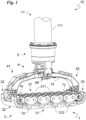
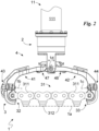
- Each limb 11, illustrated in Figs. 1 and 2 can comprise an anchoring body 111 of the robotic foot 1 to the rest of the lower limb 11 and therefore of the robot 10.
- the robot 10 can comprise, in addition to modules identifying a limb 11, modules configured to perform other functions such as identifying additional limbs such as gripping and/or handling of an object.
- the robot 10 can comprise two modules each identifying a limb 11; two modules each identifying an additional limb (in detail an upper limb); a module identifying the torso and a module identifying the head of said robot 10.
- the robot 10 can comprise at least one motor 12 for actuating said module.
- the motor 12 can be configured to move the module with respect to a different module and in particular at least one module identifying the limb 11 with respect to the rest of the robot 10 so as to allow said robot 10 to move on said support surface.
- the motor 12 can be configured to actuate at least one module allowing it to perform an operation such as a gripping.
- the motor 12 can be electric.
- the robot 10 can comprise a control unit 13 of the robot 10 and in particular of the at least one motor 12.
- the robot 10 can comprise a power supply system 14 of the robot such as a battery and/or a connection to an external network.
- a power supply system 14 of the robot such as a battery and/or a connection to an external network.
- the robotic foot 1 comprises an attachment 2, preferably integral, of the foot 1 to an external object, in detail to the robot 10, in more detail to the limb 11 and more in detail still to the anchoring body 111.
- the robotic foot 1 comprises a contact organ 3 defining the contact area 1a.
- the contact organ 3 is configured to vary the profile of the contact area 1a which can therefore be flat or deformed.
- the contact organ 3 comprises at least one chain 31 defining the contact area 1a.
- it comprises a plurality of chains 31 suitably parallel to each other.
- the member 3 comprises at least three chains 31 and for example four.
- Each chain 31 defines a first end and a second end.
- the axis of rotation between the meshes is substantially parallel to the contact area 1a regardless of the profile of the contact area 1a.
- the meshes 311 belonging to distinct chains 31 may not be constrained to each other so as to allow independent deformation of the chains 31.
- Each chain 31 can comprise for each mesh 311 a cleat 312 defining at least one sector of the contact area 1a.
- the cleat 312 can be made of elastomeric material or other material configured to absorb the forces/impacts upon contact between the contact area 1a and the support surface.
- the contact area can be defined by the area enclosing (circumscribed) to the portion of said at least one chain of contact with the support surface, in detail to the meshs 311 in contact with the support surface and in more detail by the cleats 312 and in detail the surfaces of the cleats 312 in contact with the support surface.
- the contact organ 3 can comprise a first support 32 constrained to each chain 31 at the first end and a second support 33 constrained to each chain 31 at the second end.
- the first support 32 can be placed in correspondence with the front face.
- the second support 33 can be placed in correspondence with the rear face.
- the supports 32 and 33 enclose the at least one chain 31 between them.
- the supports 32 and 33 identify the only constraints between meshes 311 of different chains 31.
- the first support 32 is hinged to each chain 31 at the mesh 311 defining the first end allowing said meshes 311 to rotate with respect to the first support 32 suitably idly.
- the axis of rotation between the first support 32 and at least one chain 31 is substantially parallel to the contact area 1a.
- the second support 33 is hinged to each chain 31 at the mesh 311 defining the second end allowing said mesh 311 to rotate with respect to the second support 33 suitably idly.
- the axis of rotation between the second support 33 and at least one chain 31 is substantially parallel to the contact area 1a.
- the robotic foot 1 comprises a constraint block 4 of the contact organ 3 to the attachment 2.
- the constraint block 4 is constrained in a compliant way and hinged in detail to the contact organ 3.
- the constraint block 4 comprises a first arm 41 subtended between the first end of the chain 3 and attachment 2 and in detail between the first support 32 and attachment 2; and a second arm 42 subtended between the second end of the chain 3 and the attachment 2 and in detail between the second support 33 and the attachment 2.
- the first arm 41 is constrained, suitably not directly, to the chain 3 at the first end. In detail, it is hinged to the chain 3 and to be more precise to the first support 32.
- the second arm 42 is suitably not directly connected to the chain 3 at the second end. In detail, it is hinged to the chain 3 and to be more precise to the second support 33.
- the constraint block 4 can comprise a first hinge 43 defining a first axis of rotation 1b.
- the first hinge 43 is configured to allow a first rotation, suitably idle, between the contact organ 3 and the constraint block 4. In particular, between the first arm 41 and the contact organ 3.
- the first rotation is between the first arm 41 and the first support 32 and therefore between the first arm 41 and at least the chain 31.
- the first axis of rotation 1b can be practically transverse to the support area 1a and preferably incident to the support area 1a suitably at least in a flat profile.
- the first axis 1b can define with respect to the support area 1a a first angle of inclination with an amplitude almost lower than 30° in detail substantially comprised between 30° and 1°, preferably between 10° and 3°.
- the width of the first angle can be almost equal to 6°.
- the constraint block 4 can comprise a second hinge 44 defining a second axis of rotation 1c.
- the second hinge 44 is configured to allow a second rotation, suitably idle, between the contact organ 3 and the constraint block 4, in particular, between the second arm 42 and the contact organ 3.
- a second rotation is between the second arm 41 and the second support 33 and therefore between second arm 41 and at least chain 31.
- the second hinge 44 can be placed in correspondence with the rear face and preferably external to the projection of the contact area 1a, said projection being almost perpendicular to the contact area 1a having flat profile.
- the second hinge 44 can be on the opposite side to the first hinge 43 with respect to the contact organ 3 and, to be more precise, to the contact area 1a.
- the second axis of rotation 1c can have an inclination opposite to the first axis 1b.
- the first axis 1b and the second axis 1c are substantially coplanar and to be precise, incident with each other.
- the second axis 1c can be substantially transverse to the area 1a and in detail incident to the support area 1a suitably at least in a flat profile.
- the width of the second angle can be almost equal to 6°.
- first hinge 43 and the second hinge 44 are configured to allow distinct rotations around the first axis of rotation 1b and the second axis of rotation 1c causing a variation in the profile of the contact area 1a.
- the constraint block 4 can comprise an additional hinge 45 defining an additional axis of rotation 1d.
- the additional hinge 45 is configured to allow an additional rotation, suitably idle, between the attachment 2 and the constraint block 4 and in particular between the attachment 2 and each arm 41 and 42.
- the additional axis of rotation 1d can be practically parallel to the support area 1a and substantially incident in detail the projection of the centre of gravity of the contact area 1a having a flat profile.
- the additional axis of rotation 1d can be substantially perpendicular to the first axis of rotation 1b.
- First axis 1b and additional axis 1d can be skewed.
- first arm 41 can be configured to distance the first hinge 43 and the additional hinge 45 and then the first axis 1b and the additional axis 1d from each other.
- the minimum distance, calculated along the perpendicular to the contact area 1a when in flat profile, between said axes 1b and 1d is at least equal to 0.5 cm and in detail to 1 cm. It can be substantially comprised between 1 cm and 10 cm in detail between 2 cm and 5 cm and more precisely between 3 cm and 4 cm.
- the additional rotation axis 1d can be substantially perpendicular to the second rotation axis 1c.
- the second arm 42 can be configured to distance the second hinge 44 and the additional hinge 45 and therefore the second axis 1c and the additional axis 1d from each other.
- the minimum distance, calculated along the perpendicular to the contact area 1a when in flat profile, between said axes 1c and 1d is at least equal to 0.5 cm and in detail to 1 cm. It can be substantially comprised between 1 cm and 10 cm in detail between 2 cm and 5 cm and more precisely between 3 cm and 4 cm.
- the additional axis 1d can be equidistant from the ends of the chains 31 in detail from the supports 32 and 33.
- the constraint block 4 comprises elastic means 46 adapted to mutually spread the arms 41 and 42 keeping the at least one chain 31 under tension and therefore opposing a deformation of said chain 31 when in contact with an irregular and/or non-flat support surface.
- the elastic means 46 can be associated with the additional hinge 45 so as to oppose a variation (in detail a decrease) in the spreading angle between the arms 41 and 42.
- the angle of spread can be centred on the additional axis of rotation 1d.
- the constraint block 4 comprises a first limit switch 47 for the first arm 41 and a second limit switch 48 for the second arm 42.
- Each limit switch 47 and 48 is configured to limit the mutual approach of the arms 41 and 42 and therefore defines a minimum value of the spreading angle between arms 41 and 42.
- Said minimum value of the spreading angle is between 30° and 50° and for example substantially equal to 40°.
- the robotic foot 1 can comprise a sensor for measuring the deformation of the contact area 1a and therefore configured to detect the profile of the contact area 1a, or rather if the contact area 1a is flat or irregular.
- the sensors can comprise at least one sensor for measuring at least one between a first rotation around the first rotation axis 1b and a second rotation around the first axis of rotation 1c.
- the at least one sensor can be in data connection with the control unit 13.
- Said sensor system can comprise at least a first sensor 5 for measuring the first rotation around the first axis of rotation 1b in data connection with the aforementioned control unit 13.
- the control unit 13 is therefore configured to control the robot 10 according to the size of the first rotation.
- the first sensor 5 is configured to measure the rotation between the first arm 41 and the contact organ 3.
- the first sensor 5 can be an inertial sensor.
- It can be integrated in the first arm 41 and/or integrated in the contact organ 3 and in detail in the first support 32.
- the sensors can comprise only one first sensor 5.
- the sensors can comprise two first sensors 5, one integrated in the first support 32 and one in the first arm 41 to estimate the relative angle between said components.
- a sensor placed as 5 in Fig. 3 will hardly be able to measure the relative angle between 41 and 3, even more so an inertial sensor cannot.
- At least two (inertial) sensors are needed, one on 41 and the other on 32 to estimate the relative angle.
- the measure of the first rotation can be stored in the robot database.
- the sensors can comprise at least a second sensor 6 for measuring the second rotation around the second axis of rotation 1c in data connection with the control unit 13.
- the control unit 13 is therefore configured to control the robot 10 according to the measurement of the second rotation.
- the second sensor 6 is configured to measure the rotation between the second arm 42 and the contact organ 3.
- the measurement of the second rotation can be stored in the robot database.
- the sensors can comprise at least one additional sensor for measuring the additional rotation around the additional rotation axis 1d in data connection with said control unit 13.
- the second sensor 6 can be an inertial sensor.
- It can be integrated in the second arm 42 and/or integrated in the contact organ 3 and in detail in the first support 33.
- the sensors can comprise only one second sensor 6.
- the sensors can comprise two second sensors 6, one integrated in the second support 33 and one in the second arm 42 to estimate the relative angle between said components.
- the control unit 13 is therefore configured to control the robot 10 according to the extent of the additional rotation.
- the additional sensor is configured to measure the rotation between the attachment 2 and at least one arm 41 and/or 42 and optionally between the arms 41 and 42.
- the additional sensor can be an inertial sensor.
- the sensors can comprise an additional sensor for each arm in data connection with the control unit 13.
- the measurement of each additional rotation can be stored in the robot database. It can thus comprise a first additional sensor 7a for measuring the additional first rotation between the first arm 41 and attachment 2 around the additional rotation axis 1d; and a second additional sensor 7b for measuring the additional second rotation between second arm 42 and attachment 2 around the additional rotation axis 1d.
- the first additional sensor 7a can be integrated into the first arm 41.
- It can be an inertial sensor.
- the control unit 13 is configured to control the motor 12 of the robot 10 and therefore the movement of at least one limb 11 (or rather the movements of the robot 10 on the support surface) as a function of at least one measured measurement from the first sensor 5, from the at least one additional sensor (in detail both the additional sensors 7a and 7b) and preferably from the second sensor 6.
- the control unit 13 is configured to control the movement of at least one limb 11 defining for the robot a condition of equilibrium on the support surface.
- it can comprise a robot database comprising the physical and/or mechanical characteristics of the robot 10 (in detail of each module) so as to allow the unit to determine which movement to perform to define an equilibrium condition.
- the robotic foot 1 can be passive and therefore devoid of motors.
- the contact area 1a is therefore configured to remain flat (thanks to the elastic means 46) and deform only when pressed against a suitably non-flat and therefore irregular support surface.
- control unit 13 commands, for example, the lifting of the foot 10 from the support surface and its resting in a different point of the support surface.
- the rotation of the arms 41 and 42, measured by at least the additional sensors 7a and 7b, is detected by the control unit 13 which can thus identify the flat profile of the area 1a.
- This condition can be identified by the unit by means of special sensors of the robot and/or by detecting a rotation by the sensors of at least a second foot 1 of the robot 10 different from the one being moved and still in contact with the support surface.
- control unit 13 defines, for example thanks to the robot database, a new equilibrium condition and therefore the profile that the contact areas 1a must assume in order to obtain said configuration.
- the unit commands a displacement of a module, such as to vary the shape of the contact area 1a of at least one said second foot 1.
- a displacement of a module such as to vary the shape of the contact area 1a of at least one said second foot 1.
- it can command the motor 12 to move the limb 11 corresponding to the second foot 1 so as to alter the profile of the area 1a (corresponding to a modification of the interaction and therefore of the forces exchanged between area 1a and the contact surface) until the profile suitable for the new equilibrium condition is obtained.
- the contact area 1a of this foot 1 can acquire a deformed profile due to the pressure given by the unloading of the weight of the robot 10 in said contact area 1a against the support surface.
- This deformation of the area 1a involves a rotation of the constraint block 4 with respect to the attachment 2 (for example an approach of the arms 41 and 42 in opposition to the elastic means 46) and/or a rotation of the contact organ 3 with respect to the block constraint 4.
- the stability is also given by the fact that the robotic foot 1, thanks to said sensors, is able to detect the profile of the contact area 1a and therefore to determine the reaction of the ground (in the direction towards and suitably in module thanks to the database robot).
- This aspect translates into the possibility of adapting the profile of the contact area 1a in such a way as to have a reaction with the support surface suitable for creating a condition of equilibrium for the robot 10.
Landscapes
- Engineering & Computer Science (AREA)
- Chemical & Material Sciences (AREA)
- Combustion & Propulsion (AREA)
- Transportation (AREA)
- Mechanical Engineering (AREA)
- Manipulator (AREA)
Description
- The present invention relates to an adaptive robotic foot of the type specified in the preamble of the first claim.
- The object of the present invention is to be identified in a foot that functionally adapts to the actions of a robot in order to give balance and stability to the robot. Currently, most robotic feet, such as flat ones with activated ankles, favour simplicity and robustness at the expense of a reduction in functionality.
- In recent years, adaptive robotic feet have been developed, or rather able to change the shape of the foot to adapt to the ground, capable of giving greater stability and better perception of the ground.
- A prime example of an adaptive robotic foot involves the use of inflatable balls or other delicate soft components. For example,
CN202624435 introduces the possibility of making a flexible foot consisting of a flat part with rubber pads to absorb impacts;US2018311837 shows a mechanical embodiment of the sole of the foot divided into two parts; other examples involve the use of an airtight bag filled with granular material to be placed between the foot and the ground. The article "HRP-4 Walks on Soft Feet" of M. Catalano et al. discloses another type of adaptive robotic foot, provided with a deformable plantar surface. - The known technique described includes some important drawbacks.
- In detail, the known adaptive feet are difficult to use in difficult external environments and/or on soft and deformable ground such as sand or snow. Therefore, the adaptive feet are not currently able to work on all terrains guaranteeing adequate stability.
- Other drawbacks of the known adaptive robotic feet are, for example, to be identified in the mechanical complexity which determines high costs, high weights and design difficulties; in the complicated modelling that complicates their cleaty; in the complexities of control.
- In this situation, the technical task underlying the present invention is to devise an adaptive robotic foot capable of substantially obviating at least part of the aforementioned drawbacks.
- Within the scope of said technical task, an important object of the invention is to obtain an adaptive robotic foot that can be used in any condition.
- Another important object of the invention is to provide an adaptive robotic foot which has relatively simple mechanics and therefore reduced costs, low weight and limited design and control difficulties.
- The technical task and the specified aims are achieved by an adaptive robotic foot as claimed in the annexed
claim 1. Examples of preferred embodiment are described in the dependent claims. - The characteristics and advantages of the invention are clarified below by the detailed description of preferred embodiments of the invention, with reference to the accompanying drawings, in which:
- the
Fig. 1 shows, in scale, a possible application of the robotic foot according to the invention; - the
Fig. 2 illustrates, in scale, a second view ofFig. 1 ; - the
Fig. 3 shows, in scale, an exploded view of the robot foot according to the invention; - the
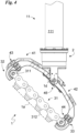
Fig. 4 shows, in scale, the robotic foot in a different position; - the
Fig. 5 illustrates, in scale, the robotic foot in a further position; - the
Fig. 6 shows, in scale, the robotic foot in a third position; and - the
Fig. 7 shows, in scale, a possible robot comprising more robotic foot according to the invention. - In the present document, the measurements, values, shapes and geometric references (such as perpendicularity and parallelism), when associated with words like "about" or other similar terms such as "approximately" or "substantially", are to be considered as except for measurement errors or inaccuracies due to production and/or manufacturing errors, and, above all, except for a slight divergence from the value, measurements, shape, or geometric reference with which it is associated. For instance, these terms, if associated with a value, preferably indicate a divergence of not more than 10% of the value.
- Moreover, when used, terms such as "first", "second", "higher", "lower", "main" and "secondary" do not necessarily identify an order, a priority of relationship or a relative position, but can simply be used to clearly distinguish between their different components.
- The measurements and data reported in this text are to be considered, unless otherwise indicated, as performed in the International Standard Atmosphere ICAO (ISO 2533:1975).
- Unless otherwise specified, as results in the following discussions, terms such as "treatment", "computing", "determination", "calculation", or similar, refer to the action and/or processes of a computer or similar electronic calculation device that manipulates and/or transforms data represented as physical, such as electronic quantities of registers of a computer system and/or memories in, other data similarly represented as physical quantities within computer systems, registers or other storage, transmission or information displaying devices.
- With reference to the figures, the adaptive robotic foot according to the invention is globally indicated with the
number 1. - It is adapted to be constrained to an external object and preferably to a
robot 10. Therobotic foot 1 defines acontact area 1a of thefoot 1 and therefore of said object external to a support surface. The support surface can be defined by a ground, a rock, a road or other structure on which thefoot 1 can rest. - As described in detail below, the
contact area 1a can have a flat profile (or rather be flat) or a deformed profile or rather be bent and/or curved due, for example, to its contact with an irregular support surface. - The
robotic foot 1 defines a front face and a rear face. Thecontact area 1a extends from said front face to said rear face. In detail, it mainly extends from the front to the rear face. - Preferably the
robotic foot 1 can be used in robotics. It can therefore be part of arobot 10. - The
robot 10 can comprise at least one module and in detail a plurality of mutually movable modules so as to allow saidrobot 10 to perform at least one operation and/or to move on a support surface. - In particular, the
robot 10 can comprise at least one module identifying alimb 11 configured to rest and therefore unload the weight of therobot 10 on a support surface and/or to allow said robot to move along said support surface. - Preferably, the
robot 10 can comprise severalmodules identifying limbs 11. For example,Fig. 7 shows arobot 10 comprising four modules each identifying alimb 11 and a fifth module identifying the central body of therobot 10 to which saidlimbs 11 are connected. - Each
limb 11 can comprise at least onerobotic foot 1. - Each
limb 11, illustrated inFigs. 1 and2 , can comprise ananchoring body 111 of therobotic foot 1 to the rest of thelower limb 11 and therefore of therobot 10. - It is highlighted how the
robot 10 can comprise, in addition to modules identifying alimb 11, modules configured to perform other functions such as identifying additional limbs such as gripping and/or handling of an object. For example, in an anthropomorphic robot therobot 10 can comprise two modules each identifying alimb 11; two modules each identifying an additional limb (in detail an upper limb); a module identifying the torso and a module identifying the head of saidrobot 10. - The
robot 10 can comprise at least onemotor 12 for actuating said module. - The
motor 12 can be configured to move the module with respect to a different module and in particular at least one module identifying thelimb 11 with respect to the rest of therobot 10 so as to allow saidrobot 10 to move on said support surface. In some cases, themotor 12 can be configured to actuate at least one module allowing it to perform an operation such as a gripping. - The
motor 12 can be electric. - The
robot 10 can comprise acontrol unit 13 of therobot 10 and in particular of the at least onemotor 12. - The
robot 10 can comprise apower supply system 14 of the robot such as a battery and/or a connection to an external network. - The
robotic foot 1 comprises anattachment 2, preferably integral, of thefoot 1 to an external object, in detail to therobot 10, in more detail to thelimb 11 and more in detail still to theanchoring body 111. - The
robotic foot 1 comprises acontact organ 3 defining thecontact area 1a. - The
contact organ 3 is configured to vary the profile of thecontact area 1a which can therefore be flat or deformed. - The
contact organ 3 comprises at least onechain 31 defining thecontact area 1a. In detail, it comprises a plurality ofchains 31 suitably parallel to each other. More in detail, themember 3 comprises at least threechains 31 and for example four. Eachchain 31 defines a first end and a second end. - Preferably each
chain 31 is an articulated chain. It can comprise at least onemesh 311 and in detail a plurality ofmeshs 311 mutually constrained so as to suitably rotate idly. - The axis of rotation between the meshes is substantially parallel to the
contact area 1a regardless of the profile of thecontact area 1a. - The
meshes 311 belonging todistinct chains 31 may not be constrained to each other so as to allow independent deformation of thechains 31. - Each
chain 31 can comprise for each mesh 311 acleat 312 defining at least one sector of thecontact area 1a. - The
cleat 312 can be made of elastomeric material or other material configured to absorb the forces/impacts upon contact between thecontact area 1a and the support surface. - The contact area can be defined by the area enclosing (circumscribed) to the portion of said at least one chain of contact with the support surface, in detail to the
meshs 311 in contact with the support surface and in more detail by thecleats 312 and in detail the surfaces of thecleats 312 in contact with the support surface. - The
contact organ 3 can comprise afirst support 32 constrained to eachchain 31 at the first end and asecond support 33 constrained to eachchain 31 at the second end. - The
first support 32 can be placed in correspondence with the front face. - The
second support 33 can be placed in correspondence with the rear face. - The supports 32 and 33 enclose the at least one
chain 31 between them. - The supports 32 and 33 identify the only constraints between
meshes 311 ofdifferent chains 31. - The
first support 32 is hinged to eachchain 31 at themesh 311 defining the first end allowing saidmeshes 311 to rotate with respect to thefirst support 32 suitably idly. The axis of rotation between thefirst support 32 and at least onechain 31 is substantially parallel to thecontact area 1a. - The
second support 33 is hinged to eachchain 31 at themesh 311 defining the second end allowing saidmesh 311 to rotate with respect to thesecond support 33 suitably idly. - The axis of rotation between the
second support 33 and at least onechain 31 is substantially parallel to thecontact area 1a. - The
robotic foot 1 comprises aconstraint block 4 of thecontact organ 3 to theattachment 2. - The
constraint block 4 is constrained in a compliant way and hinged in detail to thecontact organ 3. - It is constrained in a compliant way and hinged in detail to the
attachment 2. - The
constraint block 4 comprises afirst arm 41 subtended between the first end of thechain 3 andattachment 2 and in detail between thefirst support 32 andattachment 2; and asecond arm 42 subtended between the second end of thechain 3 and theattachment 2 and in detail between thesecond support 33 and theattachment 2. - The
first arm 41 is constrained, suitably not directly, to thechain 3 at the first end. In detail, it is hinged to thechain 3 and to be more precise to thefirst support 32. - The
second arm 42 is suitably not directly connected to thechain 3 at the second end. In detail, it is hinged to thechain 3 and to be more precise to thesecond support 33. - The
constraint block 4 can comprise afirst hinge 43 defining a first axis ofrotation 1b. - The
first hinge 43 can be placed in correspondence with the front face and preferably external to the projection of thecontact area 1a, said projection being almost perpendicular to thecontact area 1a having a flat profile. - The
first hinge 43 is configured to allow a first rotation, suitably idle, between thecontact organ 3 and theconstraint block 4. In particular, between thefirst arm 41 and thecontact organ 3. Preferably the first rotation is between thefirst arm 41 and thefirst support 32 and therefore between thefirst arm 41 and at least thechain 31. The first axis ofrotation 1b can be practically transverse to thesupport area 1a and preferably incident to thesupport area 1a suitably at least in a flat profile. - The
first axis 1b can define with respect to thesupport area 1a a first angle of inclination with an amplitude almost lower than 30° in detail substantially comprised between 30° and 1°, preferably between 10° and 3°. The width of the first angle can be almost equal to 6°. - The
constraint block 4 can comprise asecond hinge 44 defining a second axis ofrotation 1c. - The
second hinge 44 is configured to allow a second rotation, suitably idle, between thecontact organ 3 and theconstraint block 4, in particular, between thesecond arm 42 and thecontact organ 3. Preferably the second rotation is between thesecond arm 41 and thesecond support 33 and therefore betweensecond arm 41 and atleast chain 31. - The
second hinge 44 can be placed in correspondence with the rear face and preferably external to the projection of thecontact area 1a, said projection being almost perpendicular to thecontact area 1a having flat profile. - The
second hinge 44 can be on the opposite side to thefirst hinge 43 with respect to thecontact organ 3 and, to be more precise, to thecontact area 1a. - The second axis of
rotation 1c can have an inclination opposite to thefirst axis 1b. Preferably, thefirst axis 1b and thesecond axis 1c are substantially coplanar and to be precise, incident with each other. - The
second axis 1c can be substantially transverse to thearea 1a and in detail incident to thesupport area 1a suitably at least in a flat profile. - It can define with respect to the
contact area 1a a second angle of inclination substantially less than 30° in detail substantially comprised between 30° and 1°, preferably between 10° and 3°. The width of the second angle can be almost equal to 6°. - It should be noted that the
hinges contact organ 3 around thefirst axis 1b and thesecond axis 1c can be mutually independent. Therefore, thefirst hinge 43 and thesecond hinge 44 are configured to allow distinct rotations around the first axis ofrotation 1b and the second axis ofrotation 1c causing a variation in the profile of thecontact area 1a. - The
constraint block 4 can comprise anadditional hinge 45 defining an additional axis ofrotation 1d. - The
additional hinge 45 is configured to allow an additional rotation, suitably idle, between theattachment 2 and theconstraint block 4 and in particular between theattachment 2 and eacharm - The
additional hinge 45 is configured to allow rotation between thearms - The additional axis of
rotation 1d can be practically parallel to thesupport area 1a and substantially incident in detail the projection of the centre of gravity of thecontact area 1a having a flat profile. - The additional axis of
rotation 1d can be substantially perpendicular to the first axis ofrotation 1b. -
First axis 1b andadditional axis 1d can be skewed. - It should be noted that the
first arm 41 can be configured to distance thefirst hinge 43 and theadditional hinge 45 and then thefirst axis 1b and theadditional axis 1d from each other. The minimum distance, calculated along the perpendicular to thecontact area 1a when in flat profile, between saidaxes additional rotation axis 1d can be substantially perpendicular to thesecond rotation axis 1c. -
Second axis 1c andadditional axis 1d can be skewed. - The
second arm 42 can be configured to distance thesecond hinge 44 and theadditional hinge 45 and therefore thesecond axis 1c and theadditional axis 1d from each other. The minimum distance, calculated along the perpendicular to thecontact area 1a when in flat profile, between saidaxes contact area 1a is in a flat profile, theadditional axis 1d can be equidistant from the ends of thechains 31 in detail from thesupports - The
constraint block 4 comprises elastic means 46 adapted to mutually spread thearms chain 31 under tension and therefore opposing a deformation of saidchain 31 when in contact with an irregular and/or non-flat support surface. - The elastic means 46 can be associated with the
additional hinge 45 so as to oppose a variation (in detail a decrease) in the spreading angle between thearms - They can comprise a torsional spring connecting the two
arms 41 to each other and 42. - The angle of spread can be centred on the additional axis of
rotation 1d. - The
constraint block 4 comprises afirst limit switch 47 for thefirst arm 41 and asecond limit switch 48 for thesecond arm 42. - Each
limit switch arms arms - Said minimum value of the spreading angle is between 30° and 50° and for example substantially equal to 40°.
- The
robotic foot 1 can comprise a sensor for measuring the deformation of thecontact area 1a and therefore configured to detect the profile of thecontact area 1a, or rather if thecontact area 1a is flat or irregular. - The sensors can comprise at least one sensor for measuring at least one between a first rotation around the
first rotation axis 1b and a second rotation around the first axis ofrotation 1c. - The at least one sensor can be in data connection with the
control unit 13. - Said sensor system can comprise at least a
first sensor 5 for measuring the first rotation around the first axis ofrotation 1b in data connection with theaforementioned control unit 13. Thecontrol unit 13 is therefore configured to control therobot 10 according to the size of the first rotation. - The
first sensor 5 is configured to measure the rotation between thefirst arm 41 and thecontact organ 3. - The
first sensor 5 can be an inertial sensor. - It can be integrated in the
first arm 41 and/or integrated in thecontact organ 3 and in detail in thefirst support 32. - Preferably the sensors can comprise only one
first sensor 5. Alternatively, the sensors can comprise twofirst sensors 5, one integrated in thefirst support 32 and one in thefirst arm 41 to estimate the relative angle between said components. To be precise, a sensor placed as 5 inFig. 3 will hardly be able to measure the relative angle between 41 and 3, even more so an inertial sensor cannot. At least two (inertial) sensors are needed, one on 41 and the other on 32 to estimate the relative angle. - The measure of the first rotation can be stored in the robot database.
- The sensors can comprise at least a
second sensor 6 for measuring the second rotation around the second axis ofrotation 1c in data connection with thecontrol unit 13. Thecontrol unit 13 is therefore configured to control therobot 10 according to the measurement of the second rotation. - The
second sensor 6 is configured to measure the rotation between thesecond arm 42 and thecontact organ 3. - The measurement of the second rotation can be stored in the robot database. The sensors can comprise at least one additional sensor for measuring the additional rotation around the
additional rotation axis 1d in data connection with saidcontrol unit 13. - The
second sensor 6 can be an inertial sensor. - It can be integrated in the
second arm 42 and/or integrated in thecontact organ 3 and in detail in thefirst support 33. - Preferably the sensors can comprise only one
second sensor 6. Alternatively, the sensors can comprise twosecond sensors 6, one integrated in thesecond support 33 and one in thesecond arm 42 to estimate the relative angle between said components. - The
control unit 13 is therefore configured to control therobot 10 according to the extent of the additional rotation. - The additional sensor is configured to measure the rotation between the
attachment 2 and at least onearm 41 and/or 42 and optionally between thearms - Preferably the sensors can comprise an additional sensor for each arm in data connection with the
control unit 13. - The measurement of each additional rotation can be stored in the robot database. It can thus comprise a first
additional sensor 7a for measuring the additional first rotation between thefirst arm 41 andattachment 2 around theadditional rotation axis 1d; and a secondadditional sensor 7b for measuring the additional second rotation betweensecond arm 42 andattachment 2 around theadditional rotation axis 1d. - The first
additional sensor 7a can be integrated into thefirst arm 41. - It can be an inertial sensor.
- The second
additional sensor 7b can be integrated into thesecond arm 42. - It can be an inertial sensor.
- The
control unit 13 is configured to control therobot 10 as a function of the extent of the additional rotation of thesecond arm 42 with respect to theattachment 2. It is therefore configured to control therobot 10 as a function of the extent of the additional rotation of thefirst arm 41 with respect toattachment 2. - The
control unit 13 is configured to control themotor 12 of therobot 10 and therefore the movement of at least one limb 11 (or rather the movements of therobot 10 on the support surface) as a function of at least one measured measurement from thefirst sensor 5, from the at least one additional sensor (in detail both theadditional sensors second sensor 6. - In detail it is configured to define the profile of the
contact area 1a of each of the at least onefoot 1 of arobot 10 according to the measurements obtained from the sensors of saidfoot 1 and therefore controlling therobot 10 according to the profile of said atleast area 1a. - The
control unit 13 is configured to control the movement of at least onelimb 11 defining for the robot a condition of equilibrium on the support surface. - For this purpose, it can comprise a robot database comprising the physical and/or mechanical characteristics of the robot 10 (in detail of each module) so as to allow the unit to determine which movement to perform to define an equilibrium condition.
- Finally, it should be noted that the
robotic foot 1 can be passive and therefore devoid of motors. Thecontact area 1a is therefore configured to remain flat (thanks to the elastic means 46) and deform only when pressed against a suitably non-flat and therefore irregular support surface. - The operation of the
robotic foot 1 and therefore of therobot 10 previously described in structural terms is as follows. - When the
robot 10 moves along asupport surface 1a, thecontrol unit 13 commands, for example, the lifting of thefoot 10 from the support surface and its resting in a different point of the support surface. - Upon lifting, the
contact area 1a detaches from the support surface and therefore the weight of therobot 10 no longer presses thecontact area 1a against the support surface. Consequently, thechains 31 are subject only to the action of the elastic means 46 which, by spreading thearms chains 31 which therefore define acontact area 1a with a flat profile. - The rotation of the
arms additional sensors control unit 13 which can thus identify the flat profile of thearea 1a. - It is highlighted how the lifting of the
foot 1, removing a support from therobot 10, can bring therobot 10 to a non-equilibrium condition. This condition can be identified by the unit by means of special sensors of the robot and/or by detecting a rotation by the sensors of at least asecond foot 1 of therobot 10 different from the one being moved and still in contact with the support surface. - Once the non-equilibrium condition has been detected, the
control unit 13 defines, for example thanks to the robot database, a new equilibrium condition and therefore the profile that thecontact areas 1a must assume in order to obtain said configuration. - Then the unit commands a displacement of a module, such as to vary the shape of the
contact area 1a of at least one saidsecond foot 1. For example, it can command themotor 12 to move thelimb 11 corresponding to thesecond foot 1 so as to alter the profile of thearea 1a (corresponding to a modification of the interaction and therefore of the forces exchanged betweenarea 1a and the contact surface) until the profile suitable for the new equilibrium condition is obtained. - When the
foot 1 rests on said new point of the support surface, thecontact area 1a of thisfoot 1 can acquire a deformed profile due to the pressure given by the unloading of the weight of therobot 10 in saidcontact area 1a against the support surface. This deformation of thearea 1a involves a rotation of theconstraint block 4 with respect to the attachment 2 (for example an approach of thearms contact organ 3 with respect to theblock constraint 4. - The amplitude of these rotations, detected by the
sensors present 6, can be exploited by thecontrol unit 13 to acquire the profile of thecontact area 1a and/or command a new movement ofrobot 10. - It can be seen how the support of
foot 1 can define a condition of non-equilibrium and impose the assumption of a new condition of equilibrium. - The
robotic foot 1 and therefore therobot 10 according to the invention achieve important advantages. - In fact, the
robotic foot 1 is able to guarantee excellent stability on any type of support surface and therefore also in difficult external environments and/or on soft and deformable ground such as sand or snow. - In fact, the adoption of one or
more chains 31, suitably withmeshes 311 of differentseparate chains 31, allows thecontact area 1a to perfectly adapt its shape to each support surface and therefore to all terrains. In particular, this adjustment allows thefoot 1 to maximize thecontact area 1a actually in contact with the support surface and therefore guarantees a greater grip. - The stability is also given by the fact that the
robotic foot 1, thanks to said sensors, is able to detect the profile of thecontact area 1a and therefore to determine the reaction of the ground (in the direction towards and suitably in module thanks to the database robot). This aspect translates into the possibility of adapting the profile of thecontact area 1a in such a way as to have a reaction with the support surface suitable for creating a condition of equilibrium for therobot 10. - It is evident that this result was obtained with extremely reduced sensors and therefore easy to manage.
- Another important advantage is represented by the constructive simplicity and therefore by the reduced costs and design simplicity of the
foot 1 and consequently of therobot 10. - The aforementioned advantages also result in a high ability of the
foot 1 to imitate the compliance and adaptability of the human feet thus giving therobot 10 high capabilities. - The invention is susceptible of variants falling within the scope of the inventive concept defined by the claims. In this context, all the details can be replaced by equivalent elements and the materials, shapes and dimensions can be any.
Claims (9)
- Robotic foot (1) configured to be placed on a support surface and comprising:- an attachment (2) of said robotic foot (1) to an external object;- at least one chain (31) defining a contact area (1a) of said robotic foot (1) with said support surface;- a first arm (41) joined to said chain (31) in correspondence of a first end of said chain (31) and hinged to said attachment (2);- a second arm (42) hinged to said attachment (2) and joined to said chain (31) in correspondence of a second end of said chain (31); and characterised by comprising:a first limit switch (47) for said first arm (41) and a second limit switch (48) for said second arm (42), wherein said limit switches (47, 48) are configured to limit the mutual combination of said arms (41, 42) defining a minimum value of the spreading angle between said arms (41, 42) substantially comprised between 30 ° and 50 °.- elastic means (46) suitable for mutually spread said arms (41,42) while keeping said chain (31) tense and by opposing to a deformation of said chain (31) when in contact with said irregular supporting surface;
and - Robotic foot (1) according to claim 1, comprising a supplementary hinge (45) defining an additional axis of rotation (1d) between said arms (41,42) and said attachment (2); wherein said supplementary axis of rotation (1d) is parallel to said contact area (1a).
- Robotic foot (1) according to at least one preceding claim, comprising at least three of said chain (31).
- Robotic foot (1) according to the preceding claim, wherein said chains (31) are articulated chains and each of them comprises a plurality of meshes (311) mutually joined so as to rotate among themselves.
- Robotic foot (1) according to previous claim, wherein the axis of rotation between said meshes (311) is substantially parallel to said contact area (1a).
- Robotic foot (1) according to at least one claim 4-5, wherein said meshes (311) belonging to different chains (31) are not joined among themselves so as to allow independent deformation of said chains (31).
- Robotic foot (1) according to at least one claim 4-6, wherein each of said chains (319) comprises for each of said meshes (311) a cleat (312) defining at least one sector of said contact area (1a) made in elastomeric material.
- Robotic foot (1) according to at least one preceding claim, wherein said contact organ (3) comprises a first support (32) joined to said chain (31) in correspondence of said first end and a second support (33) joined to each said chain (31) in correspondence of said second end; wherein said first arm (41) is joined to said first support (32) which therefore is interposed between said chain (31) and said first arm (41); and wherein said second arm (42) is joined to said first support (32) which therefore is interposed between said chain (31) and said second arm (42).
- Robot comprising at least one robotic foot (1) according to at least one preceding claim.
Applications Claiming Priority (2)
| Application Number | Priority Date | Filing Date | Title |
|---|---|---|---|
| IT202000024721 | 2020-10-20 | ||
| PCT/IB2021/059608 WO2022084845A1 (en) | 2020-10-20 | 2021-10-19 | Adaptive robotic foot |
Publications (3)
| Publication Number | Publication Date |
|---|---|
| EP4232347A1 EP4232347A1 (en) | 2023-08-30 |
| EP4232347B1 true EP4232347B1 (en) | 2024-07-10 |
| EP4232347C0 EP4232347C0 (en) | 2024-07-10 |
Family
ID=74194835
Family Applications (1)
| Application Number | Title | Priority Date | Filing Date |
|---|---|---|---|
| EP21806362.6A Active EP4232347B1 (en) | 2020-10-20 | 2021-10-19 | Adaptive robotic foot |
Country Status (3)
| Country | Link |
|---|---|
| US (1) | US20230391410A1 (en) |
| EP (1) | EP4232347B1 (en) |
| WO (1) | WO2022084845A1 (en) |
Families Citing this family (2)
| Publication number | Priority date | Publication date | Assignee | Title |
|---|---|---|---|---|
| US12466502B1 (en) * | 2022-09-28 | 2025-11-11 | Agility Robotics, Inc. | Method and system for improving stability in a legged robot |
| US12623412B2 (en) * | 2024-02-12 | 2026-05-12 | The Boeing Company | Forming end effector and methods of use |
Family Cites Families (3)
| Publication number | Priority date | Publication date | Assignee | Title |
|---|---|---|---|---|
| CN104590417B (en) * | 2014-12-26 | 2016-11-23 | 合肥工业大学 | A humanoid robot foot |
| CN108927796B (en) * | 2018-06-07 | 2023-04-21 | 长安大学 | A quadruped bionic robot platform based on biological characteristics |
| CN111439317B (en) * | 2020-04-24 | 2021-05-18 | 深圳国信泰富科技有限公司 | Robot track operation protection architecture |
-
2021
- 2021-10-19 EP EP21806362.6A patent/EP4232347B1/en active Active
- 2021-10-19 US US18/249,578 patent/US20230391410A1/en active Pending
- 2021-10-19 WO PCT/IB2021/059608 patent/WO2022084845A1/en not_active Ceased
Also Published As
| Publication number | Publication date |
|---|---|
| EP4232347A1 (en) | 2023-08-30 |
| WO2022084845A1 (en) | 2022-04-28 |
| US20230391410A1 (en) | 2023-12-07 |
| EP4232347C0 (en) | 2024-07-10 |
Similar Documents
| Publication | Publication Date | Title |
|---|---|---|
| US11300397B2 (en) | Compliant force sensing system | |
| US6992455B2 (en) | Leg device for leg type movable robot, and method of controlling leg type movable robot | |
| US20230391410A1 (en) | Adaptive robotic foot | |
| US9346165B1 (en) | Robotic devices with multi-degree of freedom (DOF) load cell for shear beam sensing | |
| US7093497B2 (en) | Legged mobile robot and floor reaction force detection system thereof | |
| EP0389243A3 (en) | Robot devices | |
| EP1475194B1 (en) | Leg-type moving robot and floor reaction force detection device therefor | |
| EP2895834A1 (en) | Compliant tactile sensor with fluid-filled, sponge-like material | |
| US11891288B2 (en) | Sensors having a deformable layer and a rugged cover layer and robots incorporating the same | |
| EP4232346B1 (en) | Robot with an adaptive robotic foot | |
| JP7126181B2 (en) | FOOT STRUCTURE OF LEGED MOBILE ROBOT, AND LEGED MOBILE ROBOT | |
| US11813742B2 (en) | Foot structure of legged mobile robot and legged mobile robot | |
| US20250296235A1 (en) | Robotic end effector with tactile sensing | |
| Kinoshita et al. | Dynamic sensing experiments of reaction force distributions on the sole of a walking humanoid robot | |
| EP1659378A2 (en) | Load cell protection apparatus and load detection apparatus incorporating the same. | |
| Sugaiwa et al. | A methodology for setting grasping force for picking up an object with unknown weight, friction, and stiffness | |
| JP2018167381A (en) | robot | |
| Wasserfall et al. | 3D-printed low-cost modular force sensors | |
| KR20050073861A (en) | Shoes multipurpose function test machine | |
| TWI900066B (en) | Robotic hand with micro adjustment | |
| Cordes et al. | Towards an intelligent foot for walking and climbing robots | |
| RU2675327C1 (en) | Leg foot for the walking space micro robot | |
| JPH01273755A (en) | Safety against overturning for machine |
Legal Events
| Date | Code | Title | Description |
|---|---|---|---|
| STAA | Information on the status of an ep patent application or granted ep patent |
Free format text: STATUS: UNKNOWN |
|
| STAA | Information on the status of an ep patent application or granted ep patent |
Free format text: STATUS: THE INTERNATIONAL PUBLICATION HAS BEEN MADE |
|
| PUAI | Public reference made under article 153(3) epc to a published international application that has entered the european phase |
Free format text: ORIGINAL CODE: 0009012 |
|
| STAA | Information on the status of an ep patent application or granted ep patent |
Free format text: STATUS: REQUEST FOR EXAMINATION WAS MADE |
|
| 17P | Request for examination filed |
Effective date: 20230418 |
|
| AK | Designated contracting states |
Kind code of ref document: A1 Designated state(s): AL AT BE BG CH CY CZ DE DK EE ES FI FR GB GR HR HU IE IS IT LI LT LU LV MC MK MT NL NO PL PT RO RS SE SI SK SM TR |
|
| DAV | Request for validation of the european patent (deleted) | ||
| DAX | Request for extension of the european patent (deleted) | ||
| GRAP | Despatch of communication of intention to grant a patent |
Free format text: ORIGINAL CODE: EPIDOSNIGR1 |
|
| STAA | Information on the status of an ep patent application or granted ep patent |
Free format text: STATUS: GRANT OF PATENT IS INTENDED |
|
| INTG | Intention to grant announced |
Effective date: 20240209 |
|
| GRAS | Grant fee paid |
Free format text: ORIGINAL CODE: EPIDOSNIGR3 |
|
| GRAA | (expected) grant |
Free format text: ORIGINAL CODE: 0009210 |
|
| STAA | Information on the status of an ep patent application or granted ep patent |
Free format text: STATUS: THE PATENT HAS BEEN GRANTED |
|
| AK | Designated contracting states |
Kind code of ref document: B1 Designated state(s): AL AT BE BG CH CY CZ DE DK EE ES FI FR GB GR HR HU IE IS IT LI LT LU LV MC MK MT NL NO PL PT RO RS SE SI SK SM TR |
|
| REG | Reference to a national code |
Ref country code: CH Ref legal event code: EP |
|
| REG | Reference to a national code |
Ref country code: DE Ref legal event code: R096 Ref document number: 602021015606 Country of ref document: DE |
|
| U01 | Request for unitary effect filed |
Effective date: 20240806 |
|
| U07 | Unitary effect registered |
Designated state(s): AT BE BG DE DK EE FI FR IT LT LU LV MT NL PT SE SI Effective date: 20240823 |
|
| PG25 | Lapsed in a contracting state [announced via postgrant information from national office to epo] |
Ref country code: NO Free format text: LAPSE BECAUSE OF FAILURE TO SUBMIT A TRANSLATION OF THE DESCRIPTION OR TO PAY THE FEE WITHIN THE PRESCRIBED TIME-LIMIT Effective date: 20241010 |
|
| PG25 | Lapsed in a contracting state [announced via postgrant information from national office to epo] |
Ref country code: GR Free format text: LAPSE BECAUSE OF FAILURE TO SUBMIT A TRANSLATION OF THE DESCRIPTION OR TO PAY THE FEE WITHIN THE PRESCRIBED TIME-LIMIT Effective date: 20241011 Ref country code: PL Free format text: LAPSE BECAUSE OF FAILURE TO SUBMIT A TRANSLATION OF THE DESCRIPTION OR TO PAY THE FEE WITHIN THE PRESCRIBED TIME-LIMIT Effective date: 20240710 |
|
| PG25 | Lapsed in a contracting state [announced via postgrant information from national office to epo] |
Ref country code: IS Free format text: LAPSE BECAUSE OF FAILURE TO SUBMIT A TRANSLATION OF THE DESCRIPTION OR TO PAY THE FEE WITHIN THE PRESCRIBED TIME-LIMIT Effective date: 20241110 |
|
| PG25 | Lapsed in a contracting state [announced via postgrant information from national office to epo] |
Ref country code: HR Free format text: LAPSE BECAUSE OF FAILURE TO SUBMIT A TRANSLATION OF THE DESCRIPTION OR TO PAY THE FEE WITHIN THE PRESCRIBED TIME-LIMIT Effective date: 20240710 |
|
| PG25 | Lapsed in a contracting state [announced via postgrant information from national office to epo] |
Ref country code: ES Free format text: LAPSE BECAUSE OF FAILURE TO SUBMIT A TRANSLATION OF THE DESCRIPTION OR TO PAY THE FEE WITHIN THE PRESCRIBED TIME-LIMIT Effective date: 20240710 Ref country code: RS Free format text: LAPSE BECAUSE OF FAILURE TO SUBMIT A TRANSLATION OF THE DESCRIPTION OR TO PAY THE FEE WITHIN THE PRESCRIBED TIME-LIMIT Effective date: 20241010 |
|
| PG25 | Lapsed in a contracting state [announced via postgrant information from national office to epo] |
Ref country code: RS Free format text: LAPSE BECAUSE OF FAILURE TO SUBMIT A TRANSLATION OF THE DESCRIPTION OR TO PAY THE FEE WITHIN THE PRESCRIBED TIME-LIMIT Effective date: 20241010 Ref country code: PL Free format text: LAPSE BECAUSE OF FAILURE TO SUBMIT A TRANSLATION OF THE DESCRIPTION OR TO PAY THE FEE WITHIN THE PRESCRIBED TIME-LIMIT Effective date: 20240710 Ref country code: NO Free format text: LAPSE BECAUSE OF FAILURE TO SUBMIT A TRANSLATION OF THE DESCRIPTION OR TO PAY THE FEE WITHIN THE PRESCRIBED TIME-LIMIT Effective date: 20241010 Ref country code: IS Free format text: LAPSE BECAUSE OF FAILURE TO SUBMIT A TRANSLATION OF THE DESCRIPTION OR TO PAY THE FEE WITHIN THE PRESCRIBED TIME-LIMIT Effective date: 20241110 Ref country code: HR Free format text: LAPSE BECAUSE OF FAILURE TO SUBMIT A TRANSLATION OF THE DESCRIPTION OR TO PAY THE FEE WITHIN THE PRESCRIBED TIME-LIMIT Effective date: 20240710 Ref country code: GR Free format text: LAPSE BECAUSE OF FAILURE TO SUBMIT A TRANSLATION OF THE DESCRIPTION OR TO PAY THE FEE WITHIN THE PRESCRIBED TIME-LIMIT Effective date: 20241011 Ref country code: ES Free format text: LAPSE BECAUSE OF FAILURE TO SUBMIT A TRANSLATION OF THE DESCRIPTION OR TO PAY THE FEE WITHIN THE PRESCRIBED TIME-LIMIT Effective date: 20240710 |
|
| PG25 | Lapsed in a contracting state [announced via postgrant information from national office to epo] |
Ref country code: SM Free format text: LAPSE BECAUSE OF FAILURE TO SUBMIT A TRANSLATION OF THE DESCRIPTION OR TO PAY THE FEE WITHIN THE PRESCRIBED TIME-LIMIT Effective date: 20240710 |
|
| PG25 | Lapsed in a contracting state [announced via postgrant information from national office to epo] |
Ref country code: CZ Free format text: LAPSE BECAUSE OF FAILURE TO SUBMIT A TRANSLATION OF THE DESCRIPTION OR TO PAY THE FEE WITHIN THE PRESCRIBED TIME-LIMIT Effective date: 20240710 |
|
| PG25 | Lapsed in a contracting state [announced via postgrant information from national office to epo] |
Ref country code: SK Free format text: LAPSE BECAUSE OF FAILURE TO SUBMIT A TRANSLATION OF THE DESCRIPTION OR TO PAY THE FEE WITHIN THE PRESCRIBED TIME-LIMIT Effective date: 20240710 |
|
| PLBE | No opposition filed within time limit |
Free format text: ORIGINAL CODE: 0009261 |
|
| STAA | Information on the status of an ep patent application or granted ep patent |
Free format text: STATUS: NO OPPOSITION FILED WITHIN TIME LIMIT |
|
| REG | Reference to a national code |
Ref country code: CH Ref legal event code: PL |
|
| U21 | Renewal fee for the european patent with unitary effect paid with additional fee |
Year of fee payment: 4 Effective date: 20250430 |
|
| 26N | No opposition filed |
Effective date: 20250411 |
|
| PG25 | Lapsed in a contracting state [announced via postgrant information from national office to epo] |
Ref country code: MC Free format text: LAPSE BECAUSE OF FAILURE TO SUBMIT A TRANSLATION OF THE DESCRIPTION OR TO PAY THE FEE WITHIN THE PRESCRIBED TIME-LIMIT Effective date: 20240710 |
|
| PG25 | Lapsed in a contracting state [announced via postgrant information from national office to epo] |
Ref country code: CH Free format text: LAPSE BECAUSE OF NON-PAYMENT OF DUE FEES Effective date: 20241031 |
|
| PG25 | Lapsed in a contracting state [announced via postgrant information from national office to epo] |
Ref country code: IE Free format text: LAPSE BECAUSE OF NON-PAYMENT OF DUE FEES Effective date: 20241019 |
|
| PG25 | Lapsed in a contracting state [announced via postgrant information from national office to epo] |
Ref country code: RO Free format text: LAPSE BECAUSE OF FAILURE TO SUBMIT A TRANSLATION OF THE DESCRIPTION OR TO PAY THE FEE WITHIN THE PRESCRIBED TIME-LIMIT Effective date: 20240710 |
|
| PG25 | Lapsed in a contracting state [announced via postgrant information from national office to epo] |
Ref country code: CY Free format text: LAPSE BECAUSE OF FAILURE TO SUBMIT A TRANSLATION OF THE DESCRIPTION OR TO PAY THE FEE WITHIN THE PRESCRIBED TIME-LIMIT; INVALID AB INITIO Effective date: 20211019 |
|
| PG25 | Lapsed in a contracting state [announced via postgrant information from national office to epo] |
Ref country code: HU Free format text: LAPSE BECAUSE OF FAILURE TO SUBMIT A TRANSLATION OF THE DESCRIPTION OR TO PAY THE FEE WITHIN THE PRESCRIBED TIME-LIMIT; INVALID AB INITIO Effective date: 20211019 |