EP4231790A1 - Housing assembly and electronic device - Google Patents
Housing assembly and electronic device Download PDFInfo
- Publication number
- EP4231790A1 EP4231790A1 EP22871787.2A EP22871787A EP4231790A1 EP 4231790 A1 EP4231790 A1 EP 4231790A1 EP 22871787 A EP22871787 A EP 22871787A EP 4231790 A1 EP4231790 A1 EP 4231790A1
- Authority
- EP
- European Patent Office
- Prior art keywords
- housing
- support
- support structure
- close
- assembly according
- Prior art date
- Legal status (The legal status is an assumption and is not a legal conclusion. Google has not performed a legal analysis and makes no representation as to the accuracy of the status listed.)
- Granted
Links
Images





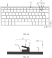
Classifications
-
- H—ELECTRICITY
- H05—ELECTRIC TECHNIQUES NOT OTHERWISE PROVIDED FOR
- H05K—PRINTED CIRCUITS; CASINGS OR CONSTRUCTIONAL DETAILS OF ELECTRIC APPARATUS; MANUFACTURE OF ASSEMBLAGES OF ELECTRICAL COMPONENTS
- H05K5/00—Casings, cabinets or drawers for electric apparatus
- H05K5/02—Details
- H05K5/0217—Mechanical details of casings
-
- G—PHYSICS
- G06—COMPUTING OR CALCULATING; COUNTING
- G06F—ELECTRIC DIGITAL DATA PROCESSING
- G06F1/00—Details not covered by groups G06F3/00 - G06F13/00 and G06F21/00
- G06F1/16—Constructional details or arrangements
- G06F1/1613—Constructional details or arrangements for portable computers
- G06F1/1633—Constructional details or arrangements of portable computers not specific to the type of enclosures covered by groups G06F1/1615 - G06F1/1626
- G06F1/1662—Details related to the integrated keyboard
-
- H—ELECTRICITY
- H01—ELECTRIC ELEMENTS
- H01H—ELECTRIC SWITCHES; RELAYS; SELECTORS; EMERGENCY PROTECTIVE DEVICES
- H01H13/00—Switches having rectilinearly-movable operating part or parts adapted for pushing or pulling in one direction only, e.g. push-button switch
- H01H13/70—Switches having rectilinearly-movable operating part or parts adapted for pushing or pulling in one direction only, e.g. push-button switch having a plurality of operating members associated with different sets of contacts, e.g. keyboard
-
- H—ELECTRICITY
- H01—ELECTRIC ELEMENTS
- H01H—ELECTRIC SWITCHES; RELAYS; SELECTORS; EMERGENCY PROTECTIVE DEVICES
- H01H13/00—Switches having rectilinearly-movable operating part or parts adapted for pushing or pulling in one direction only, e.g. push-button switch
- H01H13/70—Switches having rectilinearly-movable operating part or parts adapted for pushing or pulling in one direction only, e.g. push-button switch having a plurality of operating members associated with different sets of contacts, e.g. keyboard
- H01H13/86—Switches having rectilinearly-movable operating part or parts adapted for pushing or pulling in one direction only, e.g. push-button switch having a plurality of operating members associated with different sets of contacts, e.g. keyboard characterised by the casing, e.g. sealed casings or casings reducible in size
-
- H—ELECTRICITY
- H05—ELECTRIC TECHNIQUES NOT OTHERWISE PROVIDED FOR
- H05K—PRINTED CIRCUITS; CASINGS OR CONSTRUCTIONAL DETAILS OF ELECTRIC APPARATUS; MANUFACTURE OF ASSEMBLAGES OF ELECTRICAL COMPONENTS
- H05K5/00—Casings, cabinets or drawers for electric apparatus
- H05K5/02—Details
- H05K5/0204—Mounting supporting structures on the outside of casings
-
- H—ELECTRICITY
- H05—ELECTRIC TECHNIQUES NOT OTHERWISE PROVIDED FOR
- H05K—PRINTED CIRCUITS; CASINGS OR CONSTRUCTIONAL DETAILS OF ELECTRIC APPARATUS; MANUFACTURE OF ASSEMBLAGES OF ELECTRICAL COMPONENTS
- H05K5/00—Casings, cabinets or drawers for electric apparatus
- H05K5/02—Details
- H05K5/0217—Mechanical details of casings
- H05K5/0243—Mechanical details of casings for decorative purposes
-
- H—ELECTRICITY
- H05—ELECTRIC TECHNIQUES NOT OTHERWISE PROVIDED FOR
- H05K—PRINTED CIRCUITS; CASINGS OR CONSTRUCTIONAL DETAILS OF ELECTRIC APPARATUS; MANUFACTURE OF ASSEMBLAGES OF ELECTRICAL COMPONENTS
- H05K9/00—Screening of apparatus or components against electric or magnetic fields
- H05K9/0007—Casings
-
- G—PHYSICS
- G06—COMPUTING OR CALCULATING; COUNTING
- G06F—ELECTRIC DIGITAL DATA PROCESSING
- G06F1/00—Details not covered by groups G06F3/00 - G06F13/00 and G06F21/00
- G06F1/16—Constructional details or arrangements
- G06F1/1613—Constructional details or arrangements for portable computers
- G06F1/1615—Constructional details or arrangements for portable computers with several enclosures having relative motions, each enclosure supporting at least one I/O or computing function
- G06F1/1616—Constructional details or arrangements for portable computers with several enclosures having relative motions, each enclosure supporting at least one I/O or computing function with folding flat displays, e.g. laptop computers or notebooks having a clamshell configuration, with body parts pivoting to an open position around an axis parallel to the plane they define in closed position
-
- H—ELECTRICITY
- H01—ELECTRIC ELEMENTS
- H01H—ELECTRIC SWITCHES; RELAYS; SELECTORS; EMERGENCY PROTECTIVE DEVICES
- H01H2223/00—Casings
- H01H2223/034—Bezel
-
- H—ELECTRICITY
- H01—ELECTRIC ELEMENTS
- H01H—ELECTRIC SWITCHES; RELAYS; SELECTORS; EMERGENCY PROTECTIVE DEVICES
- H01H2227/00—Dimensions; Characteristics
- H01H2227/036—Minimise height
-
- H—ELECTRICITY
- H01—ELECTRIC ELEMENTS
- H01H—ELECTRIC SWITCHES; RELAYS; SELECTORS; EMERGENCY PROTECTIVE DEVICES
- H01H2229/00—Manufacturing
- H01H2229/034—Positioning of layers
Definitions
- This application relates to the field of communication technologies, and in particular, to a housing assembly and an electronic device.
- Keys are usually disposed on an electronic device, and a user can quickly implement man-machine interaction with the electronic device by pressing the keys.
- a key module including keys is assembled from inside to outside of the electronic device, is fastened to a housing of the electronic device, and the keys are exposed out of the housing.
- this application provides a housing assembly and an electronic device, so as to reduce a thickness of the electronic device.
- the housing assembly includes: a housing, where at least one hollowed-out portion is disposed on the housing, and the hollowed-out portion penetrates through the housing; at least one fastening structure, where the fastening structure is fastened to the housing, and a notched portion is disposed on the fastening structure; a support structure, where at least one support hole is disposed on the support structure, the support hole penetrates through the support structure, at least a part of the fastening structure passes through the support hole, and a part of the support structure close to the support hole is fastened in a notched portion;
- the fastening structure includes a protrusion portion and a first part and a second part that are located on one side of the protrusion portion that is away from the housing; one end of the first part is connected to the protrusion portion, and the other end of the first part is connected to the second part; an extension direction of the first part is the same as that of the protrusion portion, and are both parallel to a plane in which the housing is located; the
- a fastening structure is disposed on the housing, and the fastening structure includes a notched portion. A part of the support structure that is close to the support hole is fastened to the notched portion in the fastening structure, so that the support structure is fastened to the housing.
- a key module is disposed on the support structure, so that the key module can be fastened to the housing.
- no plastic bracket needs to be disposed, that is, a structure is reduced, a thickness of an electronic device is reduced, and a weight of the electronic device is reduced.
- the process procedure may be further simplified, preparation efficiency is improved, and costs are reduced.
- a material of the housing includes metal material. When the housing assembly is applied to the electronic device, the electronic device has higher quality and is more beautiful.
- the metal housing may further shield interference from environment electromagnetism to the electronic device, and heat dissipation of the electronic device is facilitated.
- a distance from a surface on one side of at least a part of the second part that is close to the housing to the housing gradually decreases. That is, in a direction perpendicular to a plane in which the housing is located, a size of an opening of the notched portion gradually decreases. In this way, the support structure may be firmly fastened in the notched portion.
- the second part in a case in which the distance from the surface on one side of at least a part of the second part that is close to the housing to the housing gradually decreases, the second part includes a first subpart and a second subpart that are continuous. One end of the first subpart is connected to the first part, and the other end of the first subpart is connected to the second part.
- a distance from a surface on one side of the first subpart that is close to the housing to the housing gradually decreases until the distance is equal to a distance from a surface on one side of the second subpart that is close to the housing to the housing.
- a distance from a surface on one side of the second part that is close to the housing to the housing gradually decreases; a distance from a surface on one side of a part of the support structure located at the notched portion that is away from the housing to the housing gradually decreases; and a surface on one side of the second part that is close to the housing is in direct contact with the surface on one side of the part of the support structure located at the notched portion that is away from the housing. In this way, the support structure can be clamped in the notched portion more stably.
- a surface on one side of the second part that is close to the housing includes an uneven surface.
- a shape of a surface of a part on one side of the support structure that is located in the notched portion and that is away from the housing matches a shape of the surface on one side of the second part that is close to the housing, so as to avoid moving of the support structure in a direction parallel to a plane in which the housing is located, thereby improving stability between the support structure and the housing.
- a protrusion structure is disposed on a surface on one side of the second part that is close to the housing; a groove is disposed on the surface on one side of the part of the support structure that is located in the notched portion and that is away from the housing; and the protrusion structure is embedded in the groove, so as to prevent the support structure from moving out of the notched portion, thereby improving stability between the support structure and the housing.
- a surface on one side of the second part that is close to the housing is a bumpy surface. This further improves stability between the support structure and the housing.
- the surface on one side of the second part that is close to the housing is the bumpy surface
- the surface on one side of the second part that is close to the housing includes a serrated surface
- an annular blind hole is disposed on a surface on one side of the support structure that is away from the housing, and the annular blind hole does not penetrate through the support structure.
- the annular blind hole is disposed around the support hole, and communicates with the support hole.
- the support structure includes a step portion, and the step portion is exposed out of the annular blind hole in a direction perpendicular to a plane in which the housing is located. At least a part of the step portion is fastened to the notched portion. This may further reduce a thickness of the housing assembly in a direction perpendicular to the plane in which the housing is located.
- the support structure includes a support portion, a connection portion, and a step portion.
- the step portion is located on one side of the connection part that is away from the support portion; and one end of the connection portion is connected to the support portion, and the other end of the connection portion is connected to the step portion.
- An extension direction of the support portion and that of the step portion are both parallel to the plane in which the housing is located; and the extension direction of the connection portion is different from the extension direction of the support portion.
- a distance from a surface on one side of the support portion that is away from the housing to the housing is greater than a distance from a surface on one side of the step portion that is away from the housing to the housing. This further reduces a thickness of the housing assembly in a direction perpendicular to the plane in which the housing is located, and expands a volume of an area enclosed by the housing and the support structure, so that some structures in the key module are disposed in the accommodating cavity.
- a material of the housing includes stainless steel, aluminum alloy, magnesium alloy, titanium alloy, or the like, which can further shield interference from environment electromagnetism to the electronic device, and facilitate heat dissipation of the electronic device.
- the housing and the fastening structure are formed integrally.
- process steps are simplified, the fastening structure and the housing do not need to be disposed separately, and the fastening structure and the housing do not need to be bonded, thereby improving preparation efficiency of the housing assembly.
- the housing and the fastening structure are formed separately.
- a location in which the fastening structure is disposed on the housing is more flexible.
- This application provides an electronic device, including any one of the foregoing housing assemblies, and can implement all effects of the housing assembly.
- a and/or B may indicate the following: Only A exists, both A and B exist, and only B exists.
- first, second, third, “fourth”, and the like are intended to distinguish between different objects but do not indicate a particular order of the objects.
- a first target object and a second target object are used to distinguish between different target objects, and are not used to describe a specific order of the target objects.
- the word such as “as an example” or “for example” is used to represent giving an example, an illustration, or a description.
- any embodiment or design solution described as “as an example” or “for example” shall not be explained as being preferred or advantageous over other embodiments or design solutions.
- the use of the word such as “as an example” or “for example” is intended to present a related concept in a specific manner.
- a plurality of means two or more than two.
- a plurality of processing units refer to two or more processing units.
- a plurality of systems refer to two or more systems; and a plurality of systems refer to two or more systems.
- the electronic device may be, for example, an electronic device with a key module, such as a keyboard, a notebook computer, an industrial computer, a personal digital assistant (personal digital assistant, PDA), a router, or a television set.
- the electronic device includes a housing.
- the housing is provided with at least one hollowed-out portion.
- a key module is located in the electronic device, is assembled from inside to outside of the electronic device, is fastened to the housing of the electronic device, and a key of the key module is exposed out of the hollowed-out portion.
- a plurality of hollowed-out portions are disposed on the housing.
- the keys on the key modules also referred to as keycaps of the keyboard
- the keyboard may be used together with the electronic device as an external input device of the electronic device.
- a keyboard serving as an external input device may include a wireless keyboard such as a Bluetooth keyboard, or may include a wired keyboard such as a keyboard connected to an electronic device such as a computer through a USB interface.
- a keyboard serving as an external input device may include a wireless keyboard such as a Bluetooth keyboard, or may include a wired keyboard such as a keyboard connected to an electronic device such as a computer through a USB interface.
- PDA personal digital assistant
- a plurality of hollowed-out portions are disposed on the housing.
- the keys on the key modules are exposed out of the plurality of hollowed-out portions.
- the electronic device is a router, a television set, or the like, for example, one hollowed-out portion is disposed on the housing.
- Akey on the key module also referred to as an appearance key or a power on key
- a specific form of the foregoing electronic device is not specifically limited in this embodiment of this application. As shown in FIG. 1 , for ease of description, that the electronic device is a notebook computer is used as an example for description below.
- the notebook computer includes a first body 10 and a second body 20.
- the first body 10 includes a housing 11, and the housing 11 includes a plurality of hollowed-out portions 111.
- the first body 10 further includes a key module 12.
- the key module 12 is located in the first body 10.
- the key module 12 includes a structure such as a key 121 (also referred to as a key cap). In some possible implementations, the key module 12 further includes a structure such as a connection connected to the key 121.
- a support structure (not shown in FIG. 1 ) is further disposed in the first body 10.
- the key module 12 is located on the support structure.
- the support structure supports the key module 12, and fastens the key module 12 to the housing 11.
- the key 121 is exposed out of the hollowed-out portion 111.
- a display 21 is disposed on the second body 20.
- a location relationship between structures in the notebook computer is specified by using an X-axis direction, a Y-axis direction, and a Z-axis direction.
- the X-axis direction is a length direction of the first body 10 of the notebook computer
- the Y-axis direction is a width direction of the first body 10 of the notebook computer
- the Z-axis direction (also referred to as a first direction) is a thickness direction of the first body 10 of the notebook computer.
- a plastic bracket 13 is disposed on the housing 11.
- the plastic bracket 13 includes a plastic column 131 protruding from one side of the plastic bracket 13 that is away from the housing 11.
- the plastic bracket 13 is formed by an adhesive dispensing process.
- the support structure 14 is fastened to the housing 11 by hot-melting the plastic column 131, and therefore further fastens the keyboard module 12 to the housing 11.
- the key 121 of the key module 12 is exposed out of the hollowed-out portion 111.
- an increased weight of the notebook computer is approximately greater than or equal to 10 g and less than or equal to 20 g.
- An increased thickness of the notebook computer in the Z-axis direction is about 0.4 mm or more and is less than or equal to 0.6 mm.
- disposing the plastic bracket 13 by an adhesive dispensing process not only makes a process procedure complex, but also increases costs.
- an embodiment of this application provides a housing assembly.
- the housing assembly includes a support structure, a housing, and a fastening structure fastened to the housing.
- the housing is provided with at least one hollowed-out portion.
- a key module is located on the support structure.
- the key module is fastened to the housing by using a support structure, and a key of the key module is exposed out of a hollowed-out portion on the housing. It may be understood that when the housing assembly is applied to a keyboard, a notebook computer, an industrial computer, and a PDA, there may be a quantity of hollowed-out portions in the housing assembly, so as to expose a plurality of key caps.
- the housing assembly When the housing assembly is applied to a router, a television set, or the like, there may be one hollowed-out parts in the housing assembly is, for example, one, so as to expose an appearance key or a power switch key.
- a support structure is directly fastened by using a fastening structure formed on the housing, so that a key module located on the support structure is fastened to the housing, no plastic bracket needs to be disposed, a thickness of the electronic device in the Z-axis direction is reduced, and a weight of the electronic device is reduced.
- an assembly process may be simplified, preparation efficiency is improved, and costs are reduced.
- the following describes the structure of the housing assembly in detail with reference to the electronic device. To describe the subsequent solution more easily and clearly, the following describes a specific structure of a housing assembly by using a housing assembly that is applied to a notebook computer as an example.
- the following content does not constitute a limitation of this application. It may be understood that when the housing assembly is applied to an electronic device such as a keyboard, a router, or a television set, an effect generated by the housing assembly is the same as the following examples in which the housing assembly is applied to a notebook computer, and a specific structure when the housing assembly is applied to an electronic device such as a keyboard, a router, or a television set is not described below.
- a housing assembly includes a housing 11 and a support structure 14.
- the housing 11 is provided with at least one hollowed-out portion 111. In the Z-axis direction, the hollowed-out portion 111 penetrates through the housing 11.
- a housing assembly further includes at least one fastening structure 15 fastened to the housing 11.
- a notched portion 151 is disposed on the fastening structure 15.
- at least one support hole 141 is disposed on a support structure 14. In the Z-axis direction, the support hole 141 penetrates through the support structure 14.
- FIG. 7 In the Z-axis direction, at least a part of the fastening structure 15 is located in the support hole 141. In addition, a part of the support structure 14 that is close to the support hole 141 is fastened to the notched portion 151, so that the support structure 14 is fastened to the fastening structure 15. Because the fastening structure 15 is fastened to the housing 11, the support structure 14 is fastened to the housing 12. Refer to FIG. 8 . Because a key module 12 is fastened to the support structure 14, the key module 12 may be fastened to the housing 11, and a key 121 of the key module 12 may be exposed out of the hollowed-out portion 111.
- a specific structure of the key module 12 and a location of the key module 12 on the support structure 14 are not specifically limited in this embodiment. Provided that the key module 12 is fastened to the housing 11 by using the support structure 14, this falls within the protection scope of this application.
- a structure for example, a connector connecting the key 121 other than the key 121 in the key module 12 is located between the housing 11 and the support structure 14. The key 121 is exposed out of the hollowed-out portion 111.
- fastening structures 15 there may be one or more fastening structures 15. This is not limited in this embodiment of this application. In this embodiment of this application, that there is one fastening structure 15 is used as an example for description.
- At least one fastening structure 15 is disposed on the housing 11, and a part of the supporting structure 14 that is close to the supporting hole 141 is fastened to a notched portion 151 in the fastening structure 15, so that the supporting structure 14 is fastened to the housing 11, and a key module is fastened to the housing 11.
- No plastic bracket needs to be disposed, a thickness of the thin electronic device in the Z-axis direction is reduced, and a weight of the electronic device is reduced.
- the process procedure may be further simplified, preparation efficiency is improved, and costs are reduced.
- a shape of the fastening structure is not limited in this embodiment, provided that the keyboard module 12 may be fastened to the housing 11 by using the fastening structure 15 and the support structure 14 together.
- the fastening structure 15 includes a protrusion portion 152 and a first part 153 and a second part 154 that are located on one side of the protrusion portion 152 that is away from the housing 11.
- One end of the first part 153 is connected to the protrusion portion 152, and the other end of the first part 153 is connected to the second part 154.
- An extension direction of the second part 154 is the same as an extension direction of the protrusion portion 152, and the extension directions are both parallel to an XY plane formed by the X-axis direction and the Y-axis direction.
- An extension direction of the first part 153 is different from the extension direction of the second part 154.
- the first part 153 extends in the Z-axis direction. Therefore, the protrusion portion 152, the first part 153, and the second part 154 are combined to form the notched portion 151.
- a material of the housing 11 is not specifically limited in this embodiment of this application.
- the material of the housing 11 includes, for example, metal.
- the material of the housing 11 may include, for example, metal material such as stainless steel, aluminum alloy, magnesium alloy, or titanium alloy.
- the metal housing may further shield interference from environment electromagnetism to the electronic device, and heat dissipation of the electronic device is facilitated.
- a material of the fastening structure 15 is not specifically limited in this embodiment of this application.
- the material of the fastening structure 15 includes, for example, metal.
- the material of the fastening structure 15 may include, for example, metal material such as stainless steel, aluminum alloy, magnesium alloy, or titanium alloy.
- the material of the fastening structure 15 is metal material, difficulty in preparing the fastening structure 15 is reduced, and preparation efficiency of the fixed structure 15 is improved.
- a material of the support structure 14 is not specifically limited in this embodiment of this application.
- the material of the support structure 14 includes, for example, metal.
- the material of the support structure 14 may be, for example, steel. When the material of the support structure 14 is steel, a support effect for the key module 12 is good, which prevents a collapse of the key module 12 that affects normal use.
- fastening structure 15 and the housing 11 may be formed separately or integrally.
- FIG. 7 is an example in which the fastening structure 15 and the housing 11 are formed separately.
- the fastening structure 15 and the housing 11 are formed separately, so that a location in which the fastening structure 15 is disposed on the housing 11 is more flexible.
- a location in which the fixed structure 15 is disposed on the housing 11 may be between two adjacent hollowed-out portions 111, and may alternatively be between four adjacent hollowed-out portions 111, for example, in an FF area in FIG. 5 .
- the fastening structure 15 is located on an edge of the housing 11, such as GG in FIG. 4 .
- connection layer 16 includes but is not limited to a double-sided adhesive tape.
- FIG. 9 is an example in which the fastening structure 15 and the housing 11 are formed integrally.
- the fastening structure 15 and the housing 11 are formed integrally, that is, the fastening structure 15 is formed while the housing 11 is formed.
- process steps are simplified, the fastening structure 15 and the housing 11 do not need to be disposed separately, and the fastening structure 15 and the housing 11 do not need to be bonded, thereby improving preparation efficiency of the housing assembly.
- fastening structure 15 and the housing 11 may be formed separately or integrally.
- the following uses an example in which the fastening structure 15 and the housing 11 are formed integrally for description.
- the foregoing example shows only a specific structure of the support structure 14, that is, as shown in FIG. 6 , at least one support hole 141 is disposed on the support structure 14. In the Z-axis direction, the support hole 141 penetrates through the support structure 14.
- this does not constitute a limitation of this application, provided that the key module 12 can be fastened to the housing 11 by using the fastening structure 15 and the support structure 14 together.
- the support structure 14 is provided with the support hole 141, and an annular blind hole 142 is further disposed on a surface on one side that is away from the housing 11. In the Z-axis direction, the annular blind hole 142 does not penetrate through the support structure 14.
- the annular blind hole 142 is disposed around the support hole 141, and communicates with the support hole 141.
- a part that the ring blind hole 142 does not penetrate is a step portion 143. At least a part of the step portion 143 is fastened to the notched portion 151, so that at least a part of the second part 154 is located in the annular blind hole 142.
- a surface of the fastening structure 15 that is away from one side of the housing 11 is flush with a surface on one side of the support structure 14 that is away from the housing 11. In this way, the thickness of the housing assembly in the Z-axis direction can be further reduced.
- the support structure 14 includes a support portion 144, a connection portion 145, and a step portion 143.
- the step portion 143 is located on one side of the connection portion 145 that is away from the support portion 144.
- One end of the connection portion 145 is connected to the support portion 144, and the other end of the connection portion 145 is connected to the step portion 143.
- An extension direction of the support portion 144 and an extension direction of the step portion 143 are both parallel to the XY plane.
- An extension direction of the connection portion 145 is different from the extension direction of the support portion 144.
- a distance H1 from a surface on one side of the support portion 144 that is away from the housing 11 to the housing 11 is greater than a distance H2 from a surface on one side of the step portion 143 that is away from the housing 11 to the housing 11.
- At least a part of the step portion 143 is fastened to the notched portion 151, and at least a part of the second part 154 is located on one side of the step portion 143 that is away from the housing 11.
- a surface on one side of the fastening structure 15 that is away from the housing 11 is flush with a surface on one side of the support structure 144 that is away from the housing 11.
- the thickness of the housing assembly in the Z-axis direction can be further reduced, and a volume of an area enclosed by the housing 11 and the support structure 143 can be expanded, so that some structures (for example, a connector connecting the key 121) in the key module 12 are disposed in the accommodating cavity.
- the support structure 14 includes the support portion 144, the connection portion 145, and the step portion 143 for description.
- the second part 154 includes a first subpart 1541 and a second subpart 1542.
- One end of the first subpart 1541 is connected to the first part 153, and the other end of the first subpart 1542 is connected to the second subpart 1542.
- a distance from a surface on one side of the first subpart 1541 that is close to the housing 12 to the housing 11 gradually decreases until the distance is equal to a distance from a surface on one side of the second subpart 1542 that is close to the housing 12 to the housing 11.
- a size of an opening of the notched portion 151 in the Z-axis direction decreases. In this way, the step portion 143 can be firmly fastened to the notched portion 151.
- FIG. 14 In still some other possible implementations, refer to FIG. 14 .
- a distance from a surface on one side of the second part 154 that is away from the housing 12 to the housing 11 gradually decreases; and a distance from a surface on one side of the step portion 143 that is away from the housing 12 to the housing 11 gradually decreases.
- the surface on one side of the second part 154 that is close to the housing 12 is in direct contact with the surface on one side of the step portion 143 that is away from the housing 12. That is, in the Z-axis direction, a size of an opening of the notched portion 151 is less than a thickness of the step portion 143. In this way, the step portion 143 can be clamped in the notched portion 151 more stably.
- a protrusion structure 155 is disposed on a surface on one side of the second part 154 that is close to the housing 11.
- a groove 1431 is disposed on a surface on one side of the step portion 143 that is away from the housing 12.
- the protrusion structure 155 is embedded in the groove 1431. In this way, the support structure 14 can be prevented from moving in a direction parallel to the XY plane, thereby improving stability between the support structure 14 and the housing 11.
- the groove 1431 may penetrate through the step portion 143, or may not penetrate through the step portion 143.
- a surface on one side of the second part 154 that is close to the housing 11 is a bumpy surface. In some possible implementations, the surface on one side of the second part 154 that is close to the housing 11 is a serrated surface.
- a shape of a surface on one side of the step portion 143 that is away from the housing 12 matches a shape of the surface on one side of the second part 154 that is close to the housing 11. In this way, the support structure 14 can be prevented from moving in a direction parallel to the XY plane, thereby improving stability between the support structure 14 and the housing 11.
- This application further provides a method for preparing a housing assembly.
- the method may be used to prepare, for example, the housing assembly shown in FIG. 13 .
- the method may be specifically implemented in the following steps: S161:
- As shown in FIG. 18 at least one hollowed-out portion 111 is disposed on a flat plate-shaped housing 11, and a fastener 15' is formed.
- the fastener 15' includes a protrusion portion 152, a first part 153, and a second subcomponent 154'.
- the flat plate-shaped housing 11 is cut by performing a cutting process, to form at least one hollowed-out portion 111 and a fastener 15'.
- the second subcomponent 154' of the fastener 15' has a different shape from that of the second part 154 in the fastening structure 15 shown in FIG. 13 .
- the fastener 15' may be disposed on the housing 11 by performing a stamping process, and is perpendicular to a plane in which the housing 11 is located.
- a support structure 14 is disposed on the housing 11, where the fastener 15' passes through a support hole 141 of the support structure 14, the support structure 14 includes a step portion 143 that is adjacent to the support hole 141, and at least a part of the step portion 143 is in contact with a surface on one side of the protrusion portion 152 that is away from the hou sing.
- S164 As shown in FIG. 21 , at least a part of the step portion 143 is fastened between the protrusion portion 152 and the second part 154 through riveting, so that the support structure 14 is fastened to the housing 11.
- At least a part of the step portion 143 is fastened between the protru sion portion 152 and the second part 154 through riveting, so that the support structure 14 is fastened to the housing 11.
- the formed structure is the fastening structure 15 in FIG. 13 .
Landscapes
- Engineering & Computer Science (AREA)
- Computer Hardware Design (AREA)
- Theoretical Computer Science (AREA)
- Physics & Mathematics (AREA)
- Microelectronics & Electronic Packaging (AREA)
- Human Computer Interaction (AREA)
- General Engineering & Computer Science (AREA)
- General Physics & Mathematics (AREA)
- Mathematical Physics (AREA)
- Casings For Electric Apparatus (AREA)
- Telephone Set Structure (AREA)
- Shielding Devices Or Components To Electric Or Magnetic Fields (AREA)
Abstract
Description
- This application claims priority to
Chinese Patent Application No. 202111123303.9, filed with the China National Intellectual Property Administration on September 24, 2021 - This application relates to the field of communication technologies, and in particular, to a housing assembly and an electronic device.
- With continuous development of electronic technologies, electronic devices such as laptop computers, industrial computers, routers, and television sets are widely used in people's daily life and work, which brings great convenience to people's daily life and work.
- Keys are usually disposed on an electronic device, and a user can quickly implement man-machine interaction with the electronic device by pressing the keys. A key module including keys is assembled from inside to outside of the electronic device, is fastened to a housing of the electronic device, and the keys are exposed out of the housing.
- As an electronic device becomes thinner, how to fasten a key module to a housing without increasing a thickness of the electronic device is an urgent problem to be resolved.
- To resolve the foregoing technical problem, this application provides a housing assembly and an electronic device, so as to reduce a thickness of the electronic device.
- The housing assembly includes: a housing, where at least one hollowed-out portion is disposed on the housing, and the hollowed-out portion penetrates through the housing; at least one fastening structure, where the fastening structure is fastened to the housing, and a notched portion is disposed on the fastening structure; a support structure, where at least one support hole is disposed on the support structure, the support hole penetrates through the support structure, at least a part of the fastening structure passes through the support hole, and a part of the support structure close to the support hole is fastened in a notched portion; the fastening structure includes a protrusion portion and a first part and a second part that are located on one side of the protrusion portion that is away from the housing; one end of the first part is connected to the protrusion portion, and the other end of the first part is connected to the second part; an extension direction of the first part is the same as that of the protrusion portion, and are both parallel to a plane in which the housing is located; the extension direction of the first part is different from that of the second part; the protrusion portion, the first part, and the second part are combined to form the notched portion; and a material of the housing includes metal material.
- A fastening structure is disposed on the housing, and the fastening structure includes a notched portion. A part of the support structure that is close to the support hole is fastened to the notched portion in the fastening structure, so that the support structure is fastened to the housing. A key module is disposed on the support structure, so that the key module can be fastened to the housing. In this way, no plastic bracket needs to be disposed, that is, a structure is reduced, a thickness of an electronic device is reduced, and a weight of the electronic device is reduced. In addition, in a process procedure, because a process step of forming the plastic bracket may be omitted, the process procedure may be further simplified, preparation efficiency is improved, and costs are reduced. In addition, a material of the housing includes metal material. When the housing assembly is applied to the electronic device, the electronic device has higher quality and is more beautiful. In addition, the metal housing may further shield interference from environment electromagnetism to the electronic device, and heat dissipation of the electronic device is facilitated.
- In some possible implementations, along an extension direction of the second part, a distance from a surface on one side of at least a part of the second part that is close to the housing to the housing gradually decreases. That is, in a direction perpendicular to a plane in which the housing is located, a size of an opening of the notched portion gradually decreases. In this way, the support structure may be firmly fastened in the notched portion.
- In some possible implementations, in a case in which the distance from the surface on one side of at least a part of the second part that is close to the housing to the housing gradually decreases, the second part includes a first subpart and a second subpart that are continuous. One end of the first subpart is connected to the first part, and the other end of the first subpart is connected to the second part. Along a direction in which the first subpart points to the second part, a distance from a surface on one side of the first subpart that is close to the housing to the housing gradually decreases until the distance is equal to a distance from a surface on one side of the second subpart that is close to the housing to the housing. Distances from all points of a surface on one side of the second subpart that is close to the housing to the housing are the same. In this way, the part of the support structure that is close to the support hole is fastened to the notched portion. In addition, along a direction in which the first subpart points to the second subpart, a distance from a surface on one side of the first subpart that is close to the housing to the housing gradually decreases, so that the support structure may be firmly fastened to the notched portion.
- In some possible implementations, in a case in which the distance from the surface in at least a part on one side of the second part that is close to the housing to the housing gradually decreases, along an extension direction of the second part, a distance from a surface on one side of the second part that is close to the housing to the housing gradually decreases; a distance from a surface on one side of a part of the support structure located at the notched portion that is away from the housing to the housing gradually decreases; and a surface on one side of the second part that is close to the housing is in direct contact with the surface on one side of the part of the support structure located at the notched portion that is away from the housing. In this way, the support structure can be clamped in the notched portion more stably.
- In some possible implementations, a surface on one side of the second part that is close to the housing includes an uneven surface. A shape of a surface of a part on one side of the support structure that is located in the notched portion and that is away from the housing matches a shape of the surface on one side of the second part that is close to the housing, so as to avoid moving of the support structure in a direction parallel to a plane in which the housing is located, thereby improving stability between the support structure and the housing.
- In some possible implementations, in a case in which the surface on one side of the second part that is close to the housing includes the uneven surface, a protrusion structure is disposed on a surface on one side of the second part that is close to the housing; a groove is disposed on the surface on one side of the part of the support structure that is located in the notched portion and that is away from the housing; and the protrusion structure is embedded in the groove, so as to prevent the support structure from moving out of the notched portion, thereby improving stability between the support structure and the housing.
- In some possible implementations, in a case in which the surface on one side of the second part that is close to the housing includes the uneven surface, a surface on one side of the second part that is close to the housing is a bumpy surface. This further improves stability between the support structure and the housing.
- In some possible implementations, in a case in which the surface on one side of the second part that is close to the housing is the bumpy surface, the surface on one side of the second part that is close to the housing includes a serrated surface.
- In some possible implementations, an annular blind hole is disposed on a surface on one side of the support structure that is away from the housing, and the annular blind hole does not penetrate through the support structure. The annular blind hole is disposed around the support hole, and communicates with the support hole. The support structure includes a step portion, and the step portion is exposed out of the annular blind hole in a direction perpendicular to a plane in which the housing is located. At least a part of the step portion is fastened to the notched portion. This may further reduce a thickness of the housing assembly in a direction perpendicular to the plane in which the housing is located.
- In some possible implementations, the support structure includes a support portion, a connection portion, and a step portion. Along a direction parallel to a plane in which the housing is located, the step portion is located on one side of the connection part that is away from the support portion; and one end of the connection portion is connected to the support portion, and the other end of the connection portion is connected to the step portion. An extension direction of the support portion and that of the step portion are both parallel to the plane in which the housing is located; and the extension direction of the connection portion is different from the extension direction of the support portion. In a direction perpendicular to the plane in which the housing is located, a distance from a surface on one side of the support portion that is away from the housing to the housing is greater than a distance from a surface on one side of the step portion that is away from the housing to the housing. This further reduces a thickness of the housing assembly in a direction perpendicular to the plane in which the housing is located, and expands a volume of an area enclosed by the housing and the support structure, so that some structures in the key module are disposed in the accommodating cavity.
- In some possible implementations, a material of the housing includes stainless steel, aluminum alloy, magnesium alloy, titanium alloy, or the like, which can further shield interference from environment electromagnetism to the electronic device, and facilitate heat dissipation of the electronic device.
- In some possible implementations, the housing and the fastening structure are formed integrally. When the fastening structure and the housing are formed integrally, process steps are simplified, the fastening structure and the housing do not need to be disposed separately, and the fastening structure and the housing do not need to be bonded, thereby improving preparation efficiency of the housing assembly.
- In some possible implementations, the housing and the fastening structure are formed separately. When the housing and the fastening structure are formed separately, a location in which the fastening structure is disposed on the housing is more flexible.
- This application provides an electronic device, including any one of the foregoing housing assemblies, and can implement all effects of the housing assembly.
-
-
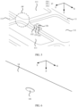
FIG. 1 is a schematic diagram of a structure of an electronic device according to an embodiment of this application; -
FIG. 2 is a sectional view of a related technology ofFIG. 1 in a direction AA'; -
FIG. 3 is a schematic diagram of a structure of a housing assembly according to an embodiment of this application; -
FIG. 4 is an exploded view of a housing assembly according to an embodiment of this application; -
FIG. 5 is an enlarged view of an area BB inFIG. 4 ; -
FIG. 6 is an enlarged view of an area CC inFIG. 4 according to an embodiment; -
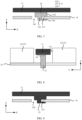
FIG. 7 is a sectional view ofFIG. 3 in a direction DD' according to this application; -
FIG. 8 is a sectional view ofFIG. 3 in a direction EE' according to this application; -
FIG. 9 is another sectional view ofFIG. 3 in the direction DD' according to this application; -
FIG. 10 is another enlarged view of the area CC inFIG. 4 according to an embodiment; -
FIG. 11 is another sectional view ofFIG. 3 in the direction DD' according to this application; -
FIG. 12 is another sectional view ofFIG. 3 in the direction DD' according to this application; -
FIG. 13 is another sectional view ofFIG. 3 in the direction DD' according to this application; -
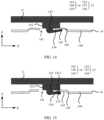
FIG. 14 is another sectional view ofFIG. 3 in the direction DD' according to this application; -
FIG. 15 is another sectional view ofFIG. 3 in the direction DD' according to this application; -
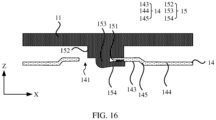
FIG. 16 is another sectional view ofFIG. 3 in the direction DD' according to this application; -
FIG. 17 is a flowchart of preparation of a housing assembly according to an embodiment of this application; -
FIG. 18 is a schematic diagram of a process of preparing a housing assembly according to an embodiment of this application; -
FIG. 19 is a schematic diagram of a process of preparing a housing assembly according to an embodiment of this application; -
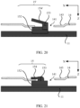
FIG. 20 is a schematic diagram of a process of preparing a housing assembly according to an embodiment of this application; and -
FIG. 21 is a schematic diagram of a process of preparing a housing assembly according to an embodiment of this application. - Reference signs:
- 10-First body; 20-Second body;
- 11-Housing; 12-Key module; 13-Plastic bracket; 14-Support structure; 15-Fastening structure; 16-Connection layer; 15'-FastenerKey;
- 111-Hollowed-out portion;
- 121-Key;
- 131-Plastic column;
- 141-Support hole; 142-Annular blind hole; 143-Step portion; 144-Support portion; 145-Connection portion;
- 151-Notched portion; 152-Protrusion portion; 153-First part; 154-Second part; 155-Protrusion structure; 154'-Second subcomponent;
- 1431-Groove;
- 1541-First subpart; and 1542-Second subpart.
- The following clearly and completely describes technical solutions in embodiments of this application with reference to accompanying drawings in the embodiments of this application. Apparently, the described embodiments are some rather than all of the embodiments of this application. Based on the embodiments of this application, all other embodiments obtained by a person of ordinary skill in the art without creative efforts fall within the protection scope of this application.
- In this specification, the term "and/or" is only used to describe an association relationship between associated objects, and indicates that three relationships may exist. For example, A and/or B may indicate the following: Only A exists, both A and B exist, and only B exists.
- In the specification and claims of this application, the terms "first", "second", "third", "fourth", and the like are intended to distinguish between different objects but do not indicate a particular order of the objects. For example, a first target object and a second target object are used to distinguish between different target objects, and are not used to describe a specific order of the target objects. In embodiments of this application, the word such as "as an example" or "for example" is used to represent giving an example, an illustration, or a description. In embodiments of this application, any embodiment or design solution described as "as an example" or "for example" shall not be explained as being preferred or advantageous over other embodiments or design solutions. To be precise, the use of the word such as "as an example" or "for example" is intended to present a related concept in a specific manner.
- In the descriptions of the embodiments of this application, unless otherwise specified, "a plurality of" means two or more than two. For example, a plurality of processing units refer to two or more processing units. A plurality of systems refer to two or more systems; and a plurality of systems refer to two or more systems.
- An embodiment of this application provides an electronic device. The electronic device may be, for example, an electronic device with a key module, such as a keyboard, a notebook computer, an industrial computer, a personal digital assistant (personal digital assistant, PDA), a router, or a television set. The electronic device includes a housing. The housing is provided with at least one hollowed-out portion. A key module is located in the electronic device, is assembled from inside to outside of the electronic device, is fastened to the housing of the electronic device, and a key of the key module is exposed out of the hollowed-out portion.
- For example, when the electronic device is a keyboard, a plurality of hollowed-out portions are disposed on the housing. The keys on the key modules (also referred to as keycaps of the keyboard) are exposed out of the plurality of hollowed-out portions. The keyboard may be used together with the electronic device as an external input device of the electronic device. In some embodiments, a keyboard serving as an external input device may include a wireless keyboard such as a Bluetooth keyboard, or may include a wired keyboard such as a keyboard connected to an electronic device such as a computer through a USB interface. When the electronic device is a notebook computer, an industrial computer, a personal digital assistant (personal digital assistant, PDA), or the like, a plurality of hollowed-out portions are disposed on the housing. The keys on the key modules (also referred to as keycaps of the keyboard) are exposed out of the plurality of hollowed-out portions. When the electronic device is a router, a television set, or the like, for example, one hollowed-out portion is disposed on the housing. Akey on the key module (also referred to as an appearance key or a power on key) is exposed out of the hollowed-out portion. A specific form of the foregoing electronic device is not specifically limited in this embodiment of this application. As shown in
FIG. 1 , for ease of description, that the electronic device is a notebook computer is used as an example for description below. - As shown in
FIG. 1 , the notebook computer includes afirst body 10 and asecond body 20. Thefirst body 10 includes ahousing 11, and thehousing 11 includes a plurality of hollowed-outportions 111. Thefirst body 10 further includes a key module 12. The key module 12 is located in thefirst body 10. The key module 12 includes a structure such as a key 121 (also referred to as a key cap). In some possible implementations, the key module 12 further includes a structure such as a connection connected to the key 121. - In addition, a support structure (not shown in
FIG. 1 ) is further disposed in thefirst body 10. The key module 12 is located on the support structure. The support structure supports the key module 12, and fastens the key module 12 to thehousing 11. The key 121 is exposed out of the hollowed-outportion 111. Adisplay 21 is disposed on thesecond body 20. - To clearly describe subsequent structural features and a location relationship between the structural features, a location relationship between structures in the notebook computer is specified by using an X-axis direction, a Y-axis direction, and a Z-axis direction. The X-axis direction is a length direction of the
first body 10 of the notebook computer, the Y-axis direction is a width direction of thefirst body 10 of the notebook computer, and the Z-axis direction (also referred to as a first direction) is a thickness direction of thefirst body 10 of the notebook computer. - Refer to
FIG. 2 . In a related technology, aplastic bracket 13 is disposed on thehousing 11. Theplastic bracket 13 includes aplastic column 131 protruding from one side of theplastic bracket 13 that is away from thehousing 11. Theplastic bracket 13 is formed by an adhesive dispensing process. Thesupport structure 14 is fastened to thehousing 11 by hot-melting theplastic column 131, and therefore further fastens the keyboard module 12 to thehousing 11. The key 121 of the key module 12 is exposed out of the hollowed-outportion 111. - However, fastening the
support structure 14 to thehousing 11 by using theplastic bracket 13 increases a weight of the notebook computer and a thickness of thefirst housing 11 in the Z-axis direction. For example, an increased weight of the notebook computer is approximately greater than or equal to 10 g and less than or equal to 20 g. An increased thickness of the notebook computer in the Z-axis direction is about 0.4 mm or more and is less than or equal to 0.6 mm. In addition, disposing theplastic bracket 13 by an adhesive dispensing process not only makes a process procedure complex, but also increases costs. - Based on this, an embodiment of this application provides a housing assembly. The housing assembly includes a support structure, a housing, and a fastening structure fastened to the housing. The housing is provided with at least one hollowed-out portion. A key module is located on the support structure. The key module is fastened to the housing by using a support structure, and a key of the key module is exposed out of a hollowed-out portion on the housing. It may be understood that when the housing assembly is applied to a keyboard, a notebook computer, an industrial computer, and a PDA, there may be a quantity of hollowed-out portions in the housing assembly, so as to expose a plurality of key caps. When the housing assembly is applied to a router, a television set, or the like, there may be one hollowed-out parts in the housing assembly is, for example, one, so as to expose an appearance key or a power switch key. A support structure is directly fastened by using a fastening structure formed on the housing, so that a key module located on the support structure is fastened to the housing, no plastic bracket needs to be disposed, a thickness of the electronic device in the Z-axis direction is reduced, and a weight of the electronic device is reduced. In addition, an assembly process may be simplified, preparation efficiency is improved, and costs are reduced.
- The following describes the structure of the housing assembly in detail with reference to the electronic device. To describe the subsequent solution more easily and clearly, the following describes a specific structure of a housing assembly by using a housing assembly that is applied to a notebook computer as an example. The following content does not constitute a limitation of this application. It may be understood that when the housing assembly is applied to an electronic device such as a keyboard, a router, or a television set, an effect generated by the housing assembly is the same as the following examples in which the housing assembly is applied to a notebook computer, and a specific structure when the housing assembly is applied to an electronic device such as a keyboard, a router, or a television set is not described below.
- As shown in
FIG. 3 and FIG. 4 , a housing assembly includes ahousing 11 and asupport structure 14. Thehousing 11 is provided with at least one hollowed-outportion 111. In the Z-axis direction, the hollowed-outportion 111 penetrates through thehousing 11. With reference toFIG. 5 , a housing assembly further includes at least onefastening structure 15 fastened to thehousing 11. A notchedportion 151 is disposed on thefastening structure 15. With reference toFIG. 6 , at least onesupport hole 141 is disposed on asupport structure 14. In the Z-axis direction, thesupport hole 141 penetrates through thesupport structure 14. - Refer to
FIG. 7 . In the Z-axis direction, at least a part of thefastening structure 15 is located in thesupport hole 141. In addition, a part of thesupport structure 14 that is close to thesupport hole 141 is fastened to the notchedportion 151, so that thesupport structure 14 is fastened to thefastening structure 15. Because thefastening structure 15 is fastened to thehousing 11, thesupport structure 14 is fastened to the housing 12. Refer toFIG. 8 . Because a key module 12 is fastened to thesupport structure 14, the key module 12 may be fastened to thehousing 11, and a key 121 of the key module 12 may be exposed out of the hollowed-outportion 111. - It should be noted that a specific structure of the key module 12 and a location of the key module 12 on the
support structure 14 are not specifically limited in this embodiment. Provided that the key module 12 is fastened to thehousing 11 by using thesupport structure 14, this falls within the protection scope of this application. For example, a structure (for example, a connector connecting the key 121) other than the key 121 in the key module 12 is located between thehousing 11 and thesupport structure 14. The key 121 is exposed out of the hollowed-outportion 111. - It should be noted that there may be one or
more fastening structures 15. This is not limited in this embodiment of this application. In this embodiment of this application, that there is onefastening structure 15 is used as an example for description. - In this application, at least one
fastening structure 15 is disposed on thehousing 11, and a part of the supportingstructure 14 that is close to the supportinghole 141 is fastened to a notchedportion 151 in thefastening structure 15, so that the supportingstructure 14 is fastened to thehousing 11, and a key module is fastened to thehousing 11. No plastic bracket needs to be disposed, a thickness of the thin electronic device in the Z-axis direction is reduced, and a weight of the electronic device is reduced. In addition, in a process procedure, because a proces s step of forming the plastic bracket may be omitted, the process procedure may be further simplified, preparation efficiency is improved, and costs are reduced. - For a shape of the
fastening structure 15, a shape of the fastening structure is not limited in this embodiment, provided that the keyboard module 12 may be fastened to thehousing 11 by using thefastening structure 15 and thesupport structure 14 together. - In some examples, still refer to
FIG. 5 andFIG. 7 . Thefastening structure 15 includes aprotrusion portion 152 and afirst part 153 and asecond part 154 that are located on one side of theprotrusion portion 152 that is away from thehousing 11. One end of thefirst part 153 is connected to theprotrusion portion 152, and the other end of thefirst part 153 is connected to thesecond part 154. An extension direction of thesecond part 154 is the same as an extension direction of theprotrusion portion 152, and the extension directions are both parallel to an XY plane formed by the X-axis direction and the Y-axis direction. An extension direction of thefirst part 153 is different from the extension direction of thesecond part 154. For example, thefirst part 153 extends in the Z-axis direction. Therefore, theprotrusion portion 152, thefirst part 153, and thesecond part 154 are combined to form the notchedportion 151. - A material of the
housing 11 is not specifically limited in this embodiment of this application. In some possible implementations, the material of thehousing 11 includes, for example, metal. For example, the material of thehousing 11 may include, for example, metal material such as stainless steel, aluminum alloy, magnesium alloy, or titanium alloy. When the material of the housing includes metal material, and the housing assembly is applied to the electronic device, the electronic device has higher quality and is more beautiful. In addition, the metal housing may further shield interference from environment electromagnetism to the electronic device, and heat dissipation of the electronic device is facilitated. - A material of the
fastening structure 15 is not specifically limited in this embodiment of this application. In some possible implementations, the material of thefastening structure 15 includes, for example, metal. For example, the material of thefastening structure 15 may include, for example, metal material such as stainless steel, aluminum alloy, magnesium alloy, or titanium alloy. When the material of thefastening structure 15 is metal material, difficulty in preparing thefastening structure 15 is reduced, and preparation efficiency of the fixedstructure 15 is improved. A material of thesupport structure 14 is not specifically limited in this embodiment of this application. In some possible implementations, the material of thesupport structure 14 includes, for example, metal. For example, the material of thesupport structure 14 may be, for example, steel. When the material of thesupport structure 14 is steel, a support effect for the key module 12 is good, which prevents a collapse of the key module 12 that affects normal use. - In addition, in this application, the
fastening structure 15 and thehousing 11 may be formed separately or integrally. - Still refer to
FIG. 7. FIG. 7 is an example in which thefastening structure 15 and thehousing 11 are formed separately. Thefastening structure 15 and thehousing 11 are formed separately, so that a location in which thefastening structure 15 is disposed on thehousing 11 is more flexible. For example, refer toFIG. 5 . A location in which the fixedstructure 15 is disposed on thehousing 11 may be between two adjacent hollowed-outportions 111, and may alternatively be between four adjacent hollowed-outportions 111, for example, in an FF area inFIG. 5 . Alternatively, thefastening structure 15 is located on an edge of thehousing 11, such as GG inFIG. 4 . - It may be understood that when the
fastening structure 15 and thehousing 11 are formed separately, thefastening structure 15 is fastened to thehousing 11, for example, by using aconnection layer 16. For example, theconnection layer 16 includes but is not limited to a double-sided adhesive tape. -
FIG. 9 is an example in which thefastening structure 15 and thehousing 11 are formed integrally. Thefastening structure 15 and thehousing 11 are formed integrally, that is, thefastening structure 15 is formed while thehousing 11 is formed. When thefastening structure 15 and thehousing 11 are formed integrally, process steps are simplified, thefastening structure 15 and thehousing 11 do not need to be disposed separately, and thefastening structure 15 and thehousing 11 do not need to be bonded, thereby improving preparation efficiency of the housing assembly. - It should be noted herein that the following
fastening structure 15 and thehousing 11 may be formed separately or integrally. The following uses an example in which thefastening structure 15 and thehousing 11 are formed integrally for description. - In addition, for a specific structure of the
support structure 14, the foregoing example shows only a specific structure of thesupport structure 14, that is, as shown inFIG. 6 , at least onesupport hole 141 is disposed on thesupport structure 14. In the Z-axis direction, thesupport hole 141 penetrates through thesupport structure 14. However, this does not constitute a limitation of this application, provided that the key module 12 can be fastened to thehousing 11 by using thefastening structure 15 and thesupport structure 14 together. - In some possible implementations, refer to
FIG. 10 and FIG. 11 . Thesupport structure 14 is provided with thesupport hole 141, and an annularblind hole 142 is further disposed on a surface on one side that is away from thehousing 11. In the Z-axis direction, the annularblind hole 142 does not penetrate through thesupport structure 14. The annularblind hole 142 is disposed around thesupport hole 141, and communicates with thesupport hole 141. A part that the ringblind hole 142 does not penetrate is astep portion 143. At least a part of thestep portion 143 is fastened to the notchedportion 151, so that at least a part of thesecond part 154 is located in the annularblind hole 142. Optionally, in the Z-axis direction, a surface of thefastening structure 15 that is away from one side of thehousing 11 is flush with a surface on one side of thesupport structure 14 that is away from thehousing 11. In this way, the thickness of the housing assembly in the Z-axis direction can be further reduced. - In still another possible implementation, refer to
FIG. 12 . Thesupport structure 14 includes asupport portion 144, aconnection portion 145, and astep portion 143. In a direction parallel to the XY plane, thestep portion 143 is located on one side of theconnection portion 145 that is away from thesupport portion 144. One end of theconnection portion 145 is connected to thesupport portion 144, and the other end of theconnection portion 145 is connected to thestep portion 143. An extension direction of thesupport portion 144 and an extension direction of thestep portion 143 are both parallel to the XY plane. An extension direction of theconnection portion 145 is different from the extension direction of thesupport portion 144. In the Z-axis direction, a distance H1 from a surface on one side of thesupport portion 144 that is away from thehousing 11 to thehousing 11 is greater than a distance H2 from a surface on one side of thestep portion 143 that is away from thehousing 11 to thehousing 11. At least a part of thestep portion 143 is fastened to the notchedportion 151, and at least a part of thesecond part 154 is located on one side of thestep portion 143 that is away from thehousing 11. Optionally, in the Z-axis direction, a surface on one side of thefastening structure 15 that is away from thehousing 11 is flush with a surface on one side of thesupport structure 144 that is away from thehousing 11. In this way, the thickness of the housing assembly in the Z-axis direction can be further reduced, and a volume of an area enclosed by thehousing 11 and thesupport structure 143 can be expanded, so that some structures (for example, a connector connecting the key 121) in the key module 12 are disposed in the accommodating cavity. - It should be noted herein that the following uses an example in which the
support structure 14 includes thesupport portion 144, theconnection portion 145, and thestep portion 143 for description. - In addition, this further improves stability between the
support structure 14 and thehousing 11. - In some possible implementations, refer to
FIG. 13 . Thesecond part 154 includes afirst subpart 1541 and asecond subpart 1542. One end of thefirst subpart 1541 is connected to thefirst part 153, and the other end of thefirst subpart 1542 is connected to thesecond subpart 1542. Along a direction in which thefirst subpart 1541 points to thesecond subpart 1542, a distance from a surface on one side of thefirst subpart 1541 that is close to the housing 12 to thehousing 11 gradually decreases until the distance is equal to a distance from a surface on one side of thesecond subpart 1542 that is close to the housing 12 to thehousing 11. That is, in a direction in which thefirst subpart 1541 points to thesecond subpart 1542, a size of an opening of the notchedportion 151 in the Z-axis direction decreases. In this way, thestep portion 143 can be firmly fastened to the notchedportion 151. - In still some other possible implementations, refer to
FIG. 14 . Along a direction in which thesupport portion 144 points to thestep portion 143, a distance from a surface on one side of thesecond part 154 that is away from the housing 12 to thehousing 11 gradually decreases; and a distance from a surface on one side of thestep portion 143 that is away from the housing 12 to thehousing 11 gradually decreases. The surface on one side of thesecond part 154 that is close to the housing 12 is in direct contact with the surface on one side of thestep portion 143 that is away from the housing 12. That is, in the Z-axis direction, a size of an opening of the notchedportion 151 is less than a thickness of thestep portion 143. In this way, thestep portion 143 can be clamped in the notchedportion 151 more stably. - In still some other possible implementations, refer to
FIG. 15 . Aprotrusion structure 155 is disposed on a surface on one side of thesecond part 154 that is close to thehousing 11. Agroove 1431 is disposed on a surface on one side of thestep portion 143 that is away from the housing 12. Theprotrusion structure 155 is embedded in thegroove 1431. In this way, thesupport structure 14 can be prevented from moving in a direction parallel to the XY plane, thereby improving stability between thesupport structure 14 and thehousing 11. - It should be noted herein that, along the Z-axis direction, the
groove 1431 may penetrate through thestep portion 143, or may not penetrate through thestep portion 143. - In still some other possible implementations, refer to
FIG. 16 . A surface on one side of thesecond part 154 that is close to thehousing 11 is a bumpy surface. In some possible implementations, the surface on one side of thesecond part 154 that is close to thehousing 11 is a serrated surface. A shape of a surface on one side of thestep portion 143 that is away from the housing 12 matches a shape of the surface on one side of thesecond part 154 that is close to thehousing 11. In this way, thesupport structure 14 can be prevented from moving in a direction parallel to the XY plane, thereby improving stability between thesupport structure 14 and thehousing 11. - This application further provides a method for preparing a housing assembly. The method may be used to prepare, for example, the housing assembly shown in
FIG. 13 . As shown inFIG. 17 , the method may be specifically implemented in the following steps:
S161: As shown inFIG. 18 , at least one hollowed-outportion 111 is disposed on a flat plate-shapedhousing 11, and a fastener 15' is formed. The fastener 15' includes aprotrusion portion 152, afirst part 153, and a second subcomponent 154'. - For example, the flat plate-shaped
housing 11 is cut by performing a cutting process, to form at least one hollowed-outportion 111 and a fastener 15'. - It should be noted that, in this case, the second subcomponent 154' of the fastener 15' has a different shape from that of the
second part 154 in thefastening structure 15 shown inFIG. 13 . - S162: As shown in
FIG. 19 , pressure is applied to the fastener 15', so that the fastener 15' is perpendicular to a plane in which thehousing 11 is located. - For example, the fastener 15' may be disposed on the
housing 11 by performing a stamping process, and is perpendicular to a plane in which thehousing 11 is located. - S163: As shown in
FIG. 20 , asupport structure 14 is disposed on thehousing 11, where the fastener 15' passes through asupport hole 141 of thesupport structure 14, thesupport structure 14 includes astep portion 143 that is adjacent to thesupport hole 141, and at least a part of thestep portion 143 is in contact with a surface on one side of theprotrusion portion 152 that is away from the hou sing. - For a specific structure of the
support structure 14, reference may be made to the foregoing embodiments, and details are not described again. Only one example is used herein for description. S164: As shown inFIG. 21 , at least a part of thestep portion 143 is fastened between theprotrusion portion 152 and thesecond part 154 through riveting, so that thesupport structure 14 is fastened to thehousing 11. - At least a part of the
step portion 143 is fastened between theprotru sion portion 152 and thesecond part 154 through riveting, so that thesupport structure 14 is fastened to thehousing 11. In this case, the formed structure is thefastening structure 15 inFIG. 13 . - For a specific structure and a specific location of the
fastening structure 15, reference may be made to the foregoing embodiments, and details are not described herein again. - The embodiments of this application are described above with reference to the accompanying drawings. However, this application is not limited to the foregoing specific implementations. The foregoing specific implementations are merely examples, but are not limiting. A person of ordinary skill in the art may make many forms without departing from the objective and the protection scope of the claims of this application, and such forms shall fall within the protection scope of this application.
Claims (14)
- A housing assembly, comprising:a housing, wherein at least one hollowed-out portion is disposed on the housing, and the hollowed-out portion penetrates through the housing;at least one fastening structure, wherein the fastening structure is fastened to the housing; and a notched portion is disposed on the fastening structure; anda support structure, wherein at least one support hole is disposed on the support structure, and the support hole penetrates through the support structure, whereinat least a part of the fastening structure passes through the support hole, and a portion of the support structure close to the support hole is fastened to the notched portion;the fastening structure comprises a protrusion portion and a first part and a second part that are located on one side of the protrusion portion that is away from the housing;one end of the first part is connected to the protrusion portion, and the other end of the first part is connected to the second part;an extension direction of the second part is the same as an extension direction of the protrusion portion, and both are parallel to a plane in which the housing is located;an extension direction of the first part is different from the extension direction of the second part;the protrusion portion, the first part, and the second part are combined to form the notched portion; anda material of the housing comprises a metal material.
- The housing assembly according to claim 1, wherein, along an extension direction of the second part, a distance from a surface on one side of at least a part of the second part that is close to the housing to the housing gradually decreases.
- The housing assembly according to claim 2, wherein the second part comprises a first subpart and a second subpart that are continuous;one end of the first subpart is connected to the first part, and the other end of the first subpart is connected to the second subpart; andalong a direction in which the first subpart points to the second subpart, a distance from a surface on one side of the first subpart that is close to the housing to the housing gradually decreases until the distance is equal to a distance from a surface on one side of the second subpart that is close to the housing to the housing.
- The housing assembly according to claim 2, wherein, along an extension direction of the second part, a distance from a surface on one side of the second part that is close to the housing to the housing gradually decreases;a distance from a surface on one side of a part of the support structure that is located in the notched portion and that is away from the housing to the housing gradually decreases; anda surface on one side of the second part that is close to the housing is in direct contact with the surface on one side of the part of the support structure that is located in the notched portion and that is away from the housing.
- The housing assembly according to claim 1, wherein a surface on one side of the second part that is close to the housing comprises an uneven surface; and
a shape of a surface on one side of a part of the support structure that is located in the notched portion and that is away from the housing matches a shape of the surface on one side of the second part that is close to the housing. - The housing assembly according to claim 5, wherein a protrusion structure is disposed on a surface on one side of the second part that is close to the housing;a groove is disposed on the surface on one side of the part of the support structure that is located in the notched portion and that is away from the housing; andthe protrusion structure is embedded in the groove.
- The housing assembly according to claim 5, wherein a surface on one side of the second part that is close to the housing is a bumpy surface.
- The housing assembly according to claim 7, wherein the surface on one side of the second part that is close to the housing comprises a serrated surface.
- The housing assembly according to any one of claims 1 to 8, wherein an annular blind hole is disposed on a surface on one side of the support structure that is away from the housing, the annular blind hole does not penetrate through the support structure;the annular blind hole is disposed around the support hole, and communicates with the support hole;the support structure comprises a step portion; and the step portion is exposed out of the annular blind hole in a direction perpendicular to a plane in which the housing is located; andat least a part of the step portion is fastened to the notched portion.
- The housing assembly according to any one of claims 1 to 8, wherein the support structure comprises a support portion, a connection portion, and a step portion;along a direction parallel to a plane in which the housing is located, the step portion is located on one side of the connection part that is away from the support portion; and one end of the connection portion is connected to the support portion, and the other end of the connection portion is connected to the step portion;an extension direction of the support portion and that of the step portion are both parallel to the plane in which the housing is located; and the extension direction of the connection portion is different from the extension direction of the support portion; andin a direction perpendicular to the plane in which the housing is located, a distance from a surface on one side of the support portion that is away from the housing to the housing is greater than a distance from a surface on one side of the step portion that is away from the housing to the hou sing.
- The housing assembly according to any one of claims 1 to 10, wherein the material of the housing comprises stainless steel, aluminum alloy, magnesium alloy, titanium alloy, or the like.
- The housing assembly according to any one of claims 1 to 11, wherein the housing and the fastening structure are formed integrally.
- The housing assembly according to any one of claims 1 to 12, wherein the housing and the fastening structure are formed separately.
- An electronic device, comprising the housing assembly according to any one of claims 1 to 13.
Applications Claiming Priority (2)
| Application Number | Priority Date | Filing Date | Title |
|---|---|---|---|
| CN202111123303.9A CN114025523B (en) | 2021-09-24 | 2021-09-24 | Shell assembly and electronic equipment |
| PCT/CN2022/116864 WO2023045737A1 (en) | 2021-09-24 | 2022-09-02 | Housing assembly and electronic device |
Publications (3)
| Publication Number | Publication Date |
|---|---|
| EP4231790A1 true EP4231790A1 (en) | 2023-08-23 |
| EP4231790A4 EP4231790A4 (en) | 2024-05-29 |
| EP4231790B1 EP4231790B1 (en) | 2025-07-09 |
Family
ID=80054827
Family Applications (1)
| Application Number | Title | Priority Date | Filing Date |
|---|---|---|---|
| EP22871787.2A Active EP4231790B1 (en) | 2021-09-24 | 2022-09-02 | Housing assembly and electronic device |
Country Status (4)
| Country | Link |
|---|---|
| US (1) | US12181929B2 (en) |
| EP (1) | EP4231790B1 (en) |
| CN (2) | CN115866938B (en) |
| WO (1) | WO2023045737A1 (en) |
Families Citing this family (1)
| Publication number | Priority date | Publication date | Assignee | Title |
|---|---|---|---|---|
| CN115866938B (en) | 2021-09-24 | 2025-08-29 | 荣耀终端股份有限公司 | Housing components and electronic equipment |
Family Cites Families (20)
| Publication number | Priority date | Publication date | Assignee | Title |
|---|---|---|---|---|
| US5996962A (en) | 1998-05-18 | 1999-12-07 | Chang; Tommy H. C. | Computer card retainer and process for using the same |
| CN101330532A (en) * | 2007-06-22 | 2008-12-24 | 英业达股份有限公司 | Fixing structure and electronic device using same |
| US7817418B2 (en) * | 2008-10-09 | 2010-10-19 | Dell Products, Lp | Electronic device including a support member and a method of fabricating the same |
| TWI393826B (en) | 2010-01-05 | 2013-04-21 | Wistron Corp | The foot pad of a portable electronic device |
| CN102376481B (en) | 2010-08-12 | 2014-03-26 | 富泰华工业(深圳)有限公司 | Button structure and electronic device with same |
| KR20120051169A (en) | 2010-11-12 | 2012-05-22 | 한국단자공업 주식회사 | Pcb fastening apparatus |
| JP5337279B1 (en) * | 2012-05-21 | 2013-11-06 | 株式会社東芝 | Electronics |
| CN102946512B (en) * | 2012-11-30 | 2015-05-13 | 信利光电股份有限公司 | Camera module base |
| CN104112621A (en) * | 2013-04-19 | 2014-10-22 | 鸿富锦精密工业(深圳)有限公司 | Keyboard |
| CN105225872B (en) * | 2015-09-25 | 2017-11-10 | 维沃移动通信有限公司 | A kind of press-key structure and electronic equipment |
| CN205335136U (en) * | 2016-01-24 | 2016-06-22 | 苏州摩比力特电子科技有限公司 | Handheld electronic equipment's button structure |
| CN207216635U (en) * | 2017-08-04 | 2018-04-10 | 珠海市魅族科技有限公司 | Button assembly and terminal |
| JP6669799B2 (en) * | 2018-04-02 | 2020-03-18 | レノボ・シンガポール・プライベート・リミテッド | Keyboard device and electronic equipment |
| CN209767998U (en) * | 2019-01-04 | 2019-12-10 | Oppo广东移动通信有限公司 | Electronic equipment and housing assemblies thereof |
| CN209804493U (en) * | 2019-06-21 | 2019-12-17 | 深圳市兴通铭电子科技有限公司 | Key fixing structure |
| CN110336905B (en) | 2019-07-22 | 2021-05-25 | 上海摩软通讯技术有限公司 | Fingerprint module fixing device with key function |
| CN210403563U (en) * | 2019-10-28 | 2020-04-24 | 维沃移动通信有限公司 | Key assembly and electronic equipment |
| CN112490044A (en) * | 2020-11-25 | 2021-03-12 | Oppo(重庆)智能科技有限公司 | Key assembly and electronic equipment |
| CN112908758A (en) * | 2021-03-15 | 2021-06-04 | 闻泰通讯股份有限公司 | Key mounting structure and electronic equipment |
| CN115866938B (en) | 2021-09-24 | 2025-08-29 | 荣耀终端股份有限公司 | Housing components and electronic equipment |
-
2021
- 2021-09-24 CN CN202210993001.5A patent/CN115866938B/en active Active
- 2021-09-24 CN CN202111123303.9A patent/CN114025523B/en active Active
-
2022
- 2022-09-02 EP EP22871787.2A patent/EP4231790B1/en active Active
- 2022-09-02 US US18/038,069 patent/US12181929B2/en active Active
- 2022-09-02 WO PCT/CN2022/116864 patent/WO2023045737A1/en not_active Ceased
Also Published As
| Publication number | Publication date |
|---|---|
| CN114025523B (en) | 2022-09-13 |
| CN115866938A (en) | 2023-03-28 |
| US20230409089A1 (en) | 2023-12-21 |
| EP4231790B1 (en) | 2025-07-09 |
| US12181929B2 (en) | 2024-12-31 |
| CN114025523A (en) | 2022-02-08 |
| WO2023045737A1 (en) | 2023-03-30 |
| CN115866938B (en) | 2025-08-29 |
| EP4231790A4 (en) | 2024-05-29 |
Similar Documents
| Publication | Publication Date | Title |
|---|---|---|
| AU2011318535B2 (en) | Portable computer with reveal region | |
| US9164551B2 (en) | Tablet computer | |
| CN108648946B (en) | Key assembly and electronic device | |
| EP4231790B1 (en) | Housing assembly and electronic device | |
| US11720187B2 (en) | Touchpad assembly and electronic device | |
| US20130330978A1 (en) | Audio jack for portable computing device | |
| EP4231797A1 (en) | Electronic device comprising vapor chamber | |
| US20140313656A1 (en) | Keyboard | |
| EP4246945A1 (en) | Electronic device | |
| US20240307942A1 (en) | Variable thickness extruded mobile device enclosure covers | |
| CN218243565U (en) | Electronic equipment | |
| CN107608453B (en) | Sheet, method for preparing sheet, case, and mobile terminal | |
| US7427088B1 (en) | Torsional multi-axis constraining latching system | |
| CN101464732A (en) | Keyboard module and electronic device with same | |
| CN112711339A (en) | Touch control panel device | |
| US20090161305A1 (en) | Keyboard module and electronic device having the same | |
| CN106531513A (en) | Side button fixing structure and mobile terminal | |
| CN213958842U (en) | Novel detachable key device | |
| CN112055840A (en) | Electronic subassembly and method of making the same | |
| JP2018073156A (en) | Terminal device | |
| US20030235297A1 (en) | Mobile phone with detachable covers | |
| CN116149432A (en) | clamshell laptop | |
| CN2542021Y (en) | Improved cap | |
| CN113053237A (en) | Electronic device | |
| TW201035814A (en) | Mouse |
Legal Events
| Date | Code | Title | Description |
|---|---|---|---|
| STAA | Information on the status of an ep patent application or granted ep patent |
Free format text: STATUS: THE INTERNATIONAL PUBLICATION HAS BEEN MADE |
|
| PUAI | Public reference made under article 153(3) epc to a published international application that has entered the european phase |
Free format text: ORIGINAL CODE: 0009012 |
|
| STAA | Information on the status of an ep patent application or granted ep patent |
Free format text: STATUS: REQUEST FOR EXAMINATION WAS MADE |
|
| 17P | Request for examination filed |
Effective date: 20230515 |
|
| AK | Designated contracting states |
Kind code of ref document: A1 Designated state(s): AL AT BE BG CH CY CZ DE DK EE ES FI FR GB GR HR HU IE IS IT LI LT LU LV MC MK MT NL NO PL PT RO RS SE SI SK SM TR |
|
| REG | Reference to a national code |
Ref country code: DE Ref legal event code: R079 Free format text: PREVIOUS MAIN CLASS: H05K0005020000 Ipc: G06F0001160000 Ref country code: DE Ref legal event code: R079 Ref document number: 602022017477 Country of ref document: DE Free format text: PREVIOUS MAIN CLASS: H05K0005020000 Ipc: G06F0001160000 |
|
| A4 | Supplementary search report drawn up and despatched |
Effective date: 20240425 |
|
| RIC1 | Information provided on ipc code assigned before grant |
Ipc: H01H 13/86 20060101ALI20240419BHEP Ipc: G06F 1/16 20060101AFI20240419BHEP |
|
| STAA | Information on the status of an ep patent application or granted ep patent |
Free format text: STATUS: EXAMINATION IS IN PROGRESS |
|
| 17Q | First examination report despatched |
Effective date: 20241030 |
|
| DAV | Request for validation of the european patent (deleted) | ||
| DAX | Request for extension of the european patent (deleted) | ||
| GRAP | Despatch of communication of intention to grant a patent |
Free format text: ORIGINAL CODE: EPIDOSNIGR1 |
|
| STAA | Information on the status of an ep patent application or granted ep patent |
Free format text: STATUS: GRANT OF PATENT IS INTENDED |
|
| INTG | Intention to grant announced |
Effective date: 20250205 |
|
| GRAS | Grant fee paid |
Free format text: ORIGINAL CODE: EPIDOSNIGR3 |
|
| GRAA | (expected) grant |
Free format text: ORIGINAL CODE: 0009210 |
|
| STAA | Information on the status of an ep patent application or granted ep patent |
Free format text: STATUS: THE PATENT HAS BEEN GRANTED |
|
| AK | Designated contracting states |
Kind code of ref document: B1 Designated state(s): AL AT BE BG CH CY CZ DE DK EE ES FI FR GB GR HR HU IE IS IT LI LT LU LV MC MK MT NL NO PL PT RO RS SE SI SK SM TR |
|
| REG | Reference to a national code |
Ref country code: GB Ref legal event code: FG4D |
|
| REG | Reference to a national code |
Ref country code: CH Ref legal event code: EP |
|
| REG | Reference to a national code |
Ref country code: IE Ref legal event code: FG4D |
|
| REG | Reference to a national code |
Ref country code: DE Ref legal event code: R096 Ref document number: 602022017477 Country of ref document: DE |
|
| REG | Reference to a national code |
Ref country code: NL Ref legal event code: FP |
|
| PGFP | Annual fee paid to national office [announced via postgrant information from national office to epo] |
Ref country code: NL Payment date: 20250814 Year of fee payment: 4 |
|
| PGFP | Annual fee paid to national office [announced via postgrant information from national office to epo] |
Ref country code: DE Payment date: 20250730 Year of fee payment: 4 |
|
| PGFP | Annual fee paid to national office [announced via postgrant information from national office to epo] |
Ref country code: AT Payment date: 20251020 Year of fee payment: 4 |
|
| PG25 | Lapsed in a contracting state [announced via postgrant information from national office to epo] |
Ref country code: PT Free format text: LAPSE BECAUSE OF FAILURE TO SUBMIT A TRANSLATION OF THE DESCRIPTION OR TO PAY THE FEE WITHIN THE PRESCRIBED TIME-LIMIT Effective date: 20251110 |
|
| REG | Reference to a national code |
Ref country code: AT Ref legal event code: MK05 Ref document number: 1812412 Country of ref document: AT Kind code of ref document: T Effective date: 20250709 |
|
| PG25 | Lapsed in a contracting state [announced via postgrant information from national office to epo] |
Ref country code: IS Free format text: LAPSE BECAUSE OF FAILURE TO SUBMIT A TRANSLATION OF THE DESCRIPTION OR TO PAY THE FEE WITHIN THE PRESCRIBED TIME-LIMIT Effective date: 20251109 |
|
| PG25 | Lapsed in a contracting state [announced via postgrant information from national office to epo] |
Ref country code: NO Free format text: LAPSE BECAUSE OF FAILURE TO SUBMIT A TRANSLATION OF THE DESCRIPTION OR TO PAY THE FEE WITHIN THE PRESCRIBED TIME-LIMIT Effective date: 20251009 |
|
| REG | Reference to a national code |
Ref country code: LT Ref legal event code: MG9D |
|
| PG25 | Lapsed in a contracting state [announced via postgrant information from national office to epo] |
Ref country code: AT Free format text: LAPSE BECAUSE OF FAILURE TO SUBMIT A TRANSLATION OF THE DESCRIPTION OR TO PAY THE FEE WITHIN THE PRESCRIBED TIME-LIMIT Effective date: 20250709 |
|
| PG25 | Lapsed in a contracting state [announced via postgrant information from national office to epo] |
Ref country code: FI Free format text: LAPSE BECAUSE OF FAILURE TO SUBMIT A TRANSLATION OF THE DESCRIPTION OR TO PAY THE FEE WITHIN THE PRESCRIBED TIME-LIMIT Effective date: 20250709 |
|
| PG25 | Lapsed in a contracting state [announced via postgrant information from national office to epo] |
Ref country code: HR Free format text: LAPSE BECAUSE OF FAILURE TO SUBMIT A TRANSLATION OF THE DESCRIPTION OR TO PAY THE FEE WITHIN THE PRESCRIBED TIME-LIMIT Effective date: 20250709 |
|
| PG25 | Lapsed in a contracting state [announced via postgrant information from national office to epo] |
Ref country code: GR Free format text: LAPSE BECAUSE OF FAILURE TO SUBMIT A TRANSLATION OF THE DESCRIPTION OR TO PAY THE FEE WITHIN THE PRESCRIBED TIME-LIMIT Effective date: 20251010 |
|
| PG25 | Lapsed in a contracting state [announced via postgrant information from national office to epo] |
Ref country code: SE Free format text: LAPSE BECAUSE OF FAILURE TO SUBMIT A TRANSLATION OF THE DESCRIPTION OR TO PAY THE FEE WITHIN THE PRESCRIBED TIME-LIMIT Effective date: 20250709 |
|
| PG25 | Lapsed in a contracting state [announced via postgrant information from national office to epo] |
Ref country code: LV Free format text: LAPSE BECAUSE OF FAILURE TO SUBMIT A TRANSLATION OF THE DESCRIPTION OR TO PAY THE FEE WITHIN THE PRESCRIBED TIME-LIMIT Effective date: 20250709 |
|
| PG25 | Lapsed in a contracting state [announced via postgrant information from national office to epo] |
Ref country code: PL Free format text: LAPSE BECAUSE OF FAILURE TO SUBMIT A TRANSLATION OF THE DESCRIPTION OR TO PAY THE FEE WITHIN THE PRESCRIBED TIME-LIMIT Effective date: 20250709 Ref country code: BG Free format text: LAPSE BECAUSE OF FAILURE TO SUBMIT A TRANSLATION OF THE DESCRIPTION OR TO PAY THE FEE WITHIN THE PRESCRIBED TIME-LIMIT Effective date: 20250709 |
|
| PG25 | Lapsed in a contracting state [announced via postgrant information from national office to epo] |
Ref country code: RS Free format text: LAPSE BECAUSE OF FAILURE TO SUBMIT A TRANSLATION OF THE DESCRIPTION OR TO PAY THE FEE WITHIN THE PRESCRIBED TIME-LIMIT Effective date: 20251009 |
|
| PG25 | Lapsed in a contracting state [announced via postgrant information from national office to epo] |
Ref country code: ES Free format text: LAPSE BECAUSE OF FAILURE TO SUBMIT A TRANSLATION OF THE DESCRIPTION OR TO PAY THE FEE WITHIN THE PRESCRIBED TIME-LIMIT Effective date: 20250709 |
|
| PG25 | Lapsed in a contracting state [announced via postgrant information from national office to epo] |
Ref country code: RO Free format text: LAPSE BECAUSE OF FAILURE TO SUBMIT A TRANSLATION OF THE DESCRIPTION OR TO PAY THE FEE WITHIN THE PRESCRIBED TIME-LIMIT Effective date: 20250709 |
|
| PG25 | Lapsed in a contracting state [announced via postgrant information from national office to epo] |
Ref country code: SM Free format text: LAPSE BECAUSE OF FAILURE TO SUBMIT A TRANSLATION OF THE DESCRIPTION OR TO PAY THE FEE WITHIN THE PRESCRIBED TIME-LIMIT Effective date: 20250709 |
|
| PG25 | Lapsed in a contracting state [announced via postgrant information from national office to epo] |
Ref country code: DK Free format text: LAPSE BECAUSE OF FAILURE TO SUBMIT A TRANSLATION OF THE DESCRIPTION OR TO PAY THE FEE WITHIN THE PRESCRIBED TIME-LIMIT Effective date: 20250709 |
|
| PG25 | Lapsed in a contracting state [announced via postgrant information from national office to epo] |
Ref country code: IT Free format text: LAPSE BECAUSE OF FAILURE TO SUBMIT A TRANSLATION OF THE DESCRIPTION OR TO PAY THE FEE WITHIN THE PRESCRIBED TIME-LIMIT Effective date: 20250709 |
|
| PG25 | Lapsed in a contracting state [announced via postgrant information from national office to epo] |
Ref country code: CZ Free format text: LAPSE BECAUSE OF FAILURE TO SUBMIT A TRANSLATION OF THE DESCRIPTION OR TO PAY THE FEE WITHIN THE PRESCRIBED TIME-LIMIT Effective date: 20250709 |
|
| PG25 | Lapsed in a contracting state [announced via postgrant information from national office to epo] |
Ref country code: SK Free format text: LAPSE BECAUSE OF FAILURE TO SUBMIT A TRANSLATION OF THE DESCRIPTION OR TO PAY THE FEE WITHIN THE PRESCRIBED TIME-LIMIT Effective date: 20250709 Ref country code: EE Free format text: LAPSE BECAUSE OF FAILURE TO SUBMIT A TRANSLATION OF THE DESCRIPTION OR TO PAY THE FEE WITHIN THE PRESCRIBED TIME-LIMIT Effective date: 20250709 |
|
| REG | Reference to a national code |
Ref country code: CH Ref legal event code: H13 Free format text: ST27 STATUS EVENT CODE: U-0-0-H10-H13 (AS PROVIDED BY THE NATIONAL OFFICE) Effective date: 20260504 |
|
| PLBE | No opposition filed within time limit |
Free format text: ORIGINAL CODE: 0009261 |
|
| STAA | Information on the status of an ep patent application or granted ep patent |
Free format text: STATUS: NO OPPOSITION FILED WITHIN TIME LIMIT |