EP4231601A1 - Verschlüsselung für pusch-wiederholung - Google Patents
Verschlüsselung für pusch-wiederholung Download PDFInfo
- Publication number
- EP4231601A1 EP4231601A1 EP21880629.7A EP21880629A EP4231601A1 EP 4231601 A1 EP4231601 A1 EP 4231601A1 EP 21880629 A EP21880629 A EP 21880629A EP 4231601 A1 EP4231601 A1 EP 4231601A1
- Authority
- EP
- European Patent Office
- Prior art keywords
- bit
- scrambling
- phase
- pusch
- time resource
- Prior art date
- Legal status (The legal status is an assumption and is not a legal conclusion. Google has not performed a legal analysis and makes no representation as to the accuracy of the status listed.)
- Pending
Links
- 238000000034 method Methods 0.000 claims abstract description 153
- 238000004891 communication Methods 0.000 claims description 106
- 230000015654 memory Effects 0.000 claims description 67
- 230000005540 biological transmission Effects 0.000 claims description 54
- 238000013507 mapping Methods 0.000 claims description 19
- 230000010363 phase shift Effects 0.000 claims description 3
- 230000008878 coupling Effects 0.000 claims 1
- 238000010168 coupling process Methods 0.000 claims 1
- 238000005859 coupling reaction Methods 0.000 claims 1
- 239000010410 layer Substances 0.000 description 68
- 230000006870 function Effects 0.000 description 38
- 238000005516 engineering process Methods 0.000 description 29
- 238000013473 artificial intelligence Methods 0.000 description 23
- 238000012545 processing Methods 0.000 description 20
- 230000000694 effects Effects 0.000 description 7
- 238000010586 diagram Methods 0.000 description 6
- 238000007726 management method Methods 0.000 description 6
- 238000005259 measurement Methods 0.000 description 6
- 238000012546 transfer Methods 0.000 description 6
- 230000001133 acceleration Effects 0.000 description 4
- 238000012549 training Methods 0.000 description 4
- 101710112083 Para-Rep C1 Proteins 0.000 description 3
- 125000004122 cyclic group Chemical group 0.000 description 3
- 230000003287 optical effect Effects 0.000 description 3
- 101710084218 Master replication protein Proteins 0.000 description 2
- 101000708578 Milk vetch dwarf virus (isolate N) Para-Rep C3 Proteins 0.000 description 2
- 101710112078 Para-Rep C2 Proteins 0.000 description 2
- 230000005856 abnormality Effects 0.000 description 2
- 238000004873 anchoring Methods 0.000 description 2
- 238000013461 design Methods 0.000 description 2
- 230000007774 longterm Effects 0.000 description 2
- 238000013468 resource allocation Methods 0.000 description 2
- 230000011218 segmentation Effects 0.000 description 2
- 230000011664 signaling Effects 0.000 description 2
- 239000004984 smart glass Substances 0.000 description 2
- 238000005406 washing Methods 0.000 description 2
- 102100022734 Acyl carrier protein, mitochondrial Human genes 0.000 description 1
- 101100335572 Escherichia coli (strain K12) ftsN gene Proteins 0.000 description 1
- 101000678845 Homo sapiens Acyl carrier protein, mitochondrial Proteins 0.000 description 1
- 230000027311 M phase Effects 0.000 description 1
- 230000003044 adaptive effect Effects 0.000 description 1
- 230000002776 aggregation Effects 0.000 description 1
- 238000004220 aggregation Methods 0.000 description 1
- 238000003491 array Methods 0.000 description 1
- 238000013528 artificial neural network Methods 0.000 description 1
- 230000003190 augmentative effect Effects 0.000 description 1
- 239000000969 carrier Substances 0.000 description 1
- 230000001413 cellular effect Effects 0.000 description 1
- 230000006835 compression Effects 0.000 description 1
- 238000007906 compression Methods 0.000 description 1
- 238000012937 correction Methods 0.000 description 1
- 238000007405 data analysis Methods 0.000 description 1
- 238000001514 detection method Methods 0.000 description 1
- 239000003814 drug Substances 0.000 description 1
- 239000000446 fuel Substances 0.000 description 1
- PCHJSUWPFVWCPO-UHFFFAOYSA-N gold Chemical group [Au] PCHJSUWPFVWCPO-UHFFFAOYSA-N 0.000 description 1
- 239000002346 layers by function Substances 0.000 description 1
- 238000010801 machine learning Methods 0.000 description 1
- 239000011159 matrix material Substances 0.000 description 1
- 101150106977 msgA gene Proteins 0.000 description 1
- 238000011017 operating method Methods 0.000 description 1
- 230000015541 sensory perception of touch Effects 0.000 description 1
- 230000008054 signal transmission Effects 0.000 description 1
- 238000012384 transportation and delivery Methods 0.000 description 1
- 230000001960 triggered effect Effects 0.000 description 1
- 230000000007 visual effect Effects 0.000 description 1
Images


Classifications
-
- H—ELECTRICITY
- H04—ELECTRIC COMMUNICATION TECHNIQUE
- H04L—TRANSMISSION OF DIGITAL INFORMATION, e.g. TELEGRAPHIC COMMUNICATION
- H04L27/00—Modulated-carrier systems
- H04L27/26—Systems using multi-frequency codes
-
- H—ELECTRICITY
- H04—ELECTRIC COMMUNICATION TECHNIQUE
- H04L—TRANSMISSION OF DIGITAL INFORMATION, e.g. TELEGRAPHIC COMMUNICATION
- H04L1/00—Arrangements for detecting or preventing errors in the information received
- H04L1/08—Arrangements for detecting or preventing errors in the information received by repeating transmission, e.g. Verdan system
-
- H—ELECTRICITY
- H04—ELECTRIC COMMUNICATION TECHNIQUE
- H04L—TRANSMISSION OF DIGITAL INFORMATION, e.g. TELEGRAPHIC COMMUNICATION
- H04L25/00—Baseband systems
- H04L25/02—Details ; arrangements for supplying electrical power along data transmission lines
- H04L25/03—Shaping networks in transmitter or receiver, e.g. adaptive shaping networks
- H04L25/03828—Arrangements for spectral shaping; Arrangements for providing signals with specified spectral properties
- H04L25/03866—Arrangements for spectral shaping; Arrangements for providing signals with specified spectral properties using scrambling
-
- H—ELECTRICITY
- H04—ELECTRIC COMMUNICATION TECHNIQUE
- H04L—TRANSMISSION OF DIGITAL INFORMATION, e.g. TELEGRAPHIC COMMUNICATION
- H04L27/00—Modulated-carrier systems
- H04L27/32—Carrier systems characterised by combinations of two or more of the types covered by groups H04L27/02, H04L27/10, H04L27/18 or H04L27/26
- H04L27/34—Amplitude- and phase-modulated carrier systems, e.g. quadrature-amplitude modulated carrier systems
- H04L27/36—Modulator circuits; Transmitter circuits
-
- H—ELECTRICITY
- H04—ELECTRIC COMMUNICATION TECHNIQUE
- H04L—TRANSMISSION OF DIGITAL INFORMATION, e.g. TELEGRAPHIC COMMUNICATION
- H04L5/00—Arrangements affording multiple use of the transmission path
- H04L5/003—Arrangements for allocating sub-channels of the transmission path
- H04L5/0044—Allocation of payload; Allocation of data channels, e.g. PDSCH or PUSCH
-
- H—ELECTRICITY
- H04—ELECTRIC COMMUNICATION TECHNIQUE
- H04W—WIRELESS COMMUNICATION NETWORKS
- H04W72/00—Local resource management
- H04W72/12—Wireless traffic scheduling
- H04W72/1263—Mapping of traffic onto schedule, e.g. scheduled allocation or multiplexing of flows
- H04W72/1268—Mapping of traffic onto schedule, e.g. scheduled allocation or multiplexing of flows of uplink data flows
Definitions
- This disclosure relates to wireless communication.
- next-generation communication As a growing number of communication devices require higher communication capacity, there is a need for advanced mobile broadband communication as compared to existing radio access technology (RAT).
- Massive machine-type communication which provides a variety of services anytime and anywhere by connecting a plurality of devices and a plurality of objects, is also one major issue to be considered in next-generation communication.
- designs for communication systems considering services or a user equipment (UE) sensitive to reliability and latency are under discussion.
- UE user equipment
- URLLC ultra-reliable and low-latency communication
- this technology may be referred to as new RAT or new radio (NR).
- PUSCH repetition for coverage enhancement of a UE may be considered.
- PUSCH repetition may include type A and type B.
- the repeated transmission may be performed through the same resource element (RE) using the same scrambling sequence for the same coded bit.
- the repeated transmission may become a burden in terms of inter-cell interference.
- the present specification proposes a method of differently applying scrambling according to time intervals during PUSCH repetition and an apparatus using the method.
- an energy combining gain can be obtained in PUSCH repetition transmission, while reducing the effect of interference on other signals.
- a or B may mean “only A”, “only B” or “both A and B”.
- a or B may be interpreted as “A and/or B”.
- A, B, or C may mean “only A”, “only B”, “only C”, or "any combination of A, B, C”.
- a slash (/) or comma used in the present specification may mean “and/or”.
- A/B may mean “A and/or B”.
- A/B may mean “only A”, “only B”, or “both A and B”.
- A, B, C may mean “A, B, or C”.
- At least one of A and B may mean “only A”, “only B”, or “both A and B”.
- the expression “at least one of A or B” or “at least one of A and/or B” may be interpreted as "at least one of A and B”.
- At least one of A, B, and C may mean “only A”, “only B”, “only C”, or “any combination of A, B, and C”.
- at least one of A, B, or C or “at least one of A, B, and/or C” may mean “at least one of A, B, and C”.
- a parenthesis used in the present specification may mean “for example”.
- control information PDCCH
- PDCCH control information
- a parenthesis used in the present specification may mean “for example”.
- control information i.e., PDCCH
- PDCCH control information
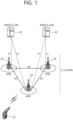
- FIG. 1 shows a wireless communication system to which the present disclosure may be applied.
- the wireless communication system may be referred to as an Evolved-UMTS Terrestrial Radio Access Network (E-UTRAN) or a Long Term Evolution (LTE)/LTE-A system.
- E-UTRAN Evolved-UMTS Terrestrial Radio Access Network
- LTE Long Term Evolution
- LTE-A Long Term Evolution
- the E-UTRAN includes at least one base station (BS) 20 which provides a control plane and a user plane to a user equipment (UE) 10.
- the UE 10 may be fixed or mobile, and may be referred to as another terminology, such as a mobile station (MS), a user terminal (UT), a subscriber station (SS), a mobile terminal (MT), a wireless device, etc.
- the BS 20 is generally a fixed station that communicates with the UE 10 and may be referred to as another terminology, such as an evolved node-B (eNB), a base transceiver system (BTS), an access point, etc.
- eNB evolved node-B
- BTS base transceiver system
- access point etc.
- the BSs 20 are interconnected by means of an X2 interface.
- the BSs 20 are also connected by means of an S1 interface to an evolved packet core (EPC) 30, more specifically, to a mobility management entity (MME) through S1-MME and to a serving gateway (S-GW) through S1-U.
- EPC evolved packet core
- MME mobility management entity
- S-GW serving gateway
- the EPC 30 includes an MME, an S-GW, and a packet data network-gateway (P-GW).
- the MME has access information of the UE or capability information of the UE, and such information is generally used for mobility management of the UE.
- the S-GW is a gateway having an E-UTRAN as an end point.
- the P-GW is a gateway having a PDN as an end point.
- Layers of a radio interface protocol between the UE and the network can be classified into a first layer (L1), a second layer (L2), and a third layer (L3) based on the lower three layers of the open system interconnection (OSI) model that is well-known in the communication system.
- a physical (PHY) layer belonging to the first layer provides an information transfer service by using a physical channel
- a radio resource control (RRC) layer belonging to the third layer serves to control a radio resource between the UE and the network.
- the RRC layer exchanges an RRC message between the UE and the BS.
- FIG. 2 is a diagram showing a wireless protocol architecture for a user plane.
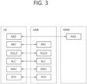
- FIG. 3 is a diagram showing a wireless protocol architecture for a control plane.
- the user plane is a protocol stack for user data transmission.
- the control plane is a protocol stack for control signal transmission.
- the PHY layer is connected to a medium access control (MAC) layer which is an upper layer of the PHY layer through a transport channel.
- MAC medium access control
- Data is transferred between the MAC layer and the PHY layer through the transport channel.
- the transport channel is classified according to how and with what characteristics data is transferred through a radio interface.
- the physical channel may be modulated according to an Orthogonal Frequency Division Multiplexing (OFDM) scheme, and use the time and frequency as radio resources.
- OFDM Orthogonal Frequency Division Multiplexing
- the functions of the MAC layer include mapping between a logical channel and a transport channel and multiplexing and demultiplexing to a transport block that is provided through a physical channel on the transport channel of a MAC Service Data Unit (SDU) that belongs to a logical channel.
- SDU MAC Service Data Unit
- the MAC layer provides service to a Radio Link Control (RLC) layer through the logical channel.
- RLC Radio Link Control
- the functions of the RLC layer include the concatenation, segmentation, and reassembly of an RLC SDU.
- QoS Quality of Service
- RB Radio Bearer
- the RLC layer provides three types of operation mode: Transparent Mode (TM), Unacknowledged Mode (UM), and Acknowledged Mode (AM).
- TM Transparent Mode
- UM Unacknowledged Mode
- AM Acknowledged Mode
- AM RLC provides error correction through an Automatic Repeat Request (ARQ).
- ARQ Automatic Repeat Request
- the RRC layer is defined only on the control plane.
- the RRC layer is related to the configuration, reconfiguration, and release of radio bearers, and is responsible for control of logical channels, transport channels, and PHY channels.
- An RB means a logical route that is provided by the first layer (PHY layer) and the second layers (MAC layer, the RLC layer, and the PDCP layer) in order to transfer data between UE and a network.
- the function of a Packet Data Convergence Protocol (PDCP) layer on the user plane includes the transfer of user data and header compression and ciphering.
- the function of the PDCP layer on the user plane further includes the transfer and encryption/integrity protection of control plane data.
- PDCP Packet Data Convergence Protocol
- What an RB is configured means a process of defining the characteristics of a wireless protocol layer and channels in order to provide specific service and configuring each detailed parameter and operating method.
- An RB can be divided into two types of a Signaling RB (SRB) and a Data RB (DRB).
- SRB Signaling RB
- DRB Data RB
- the SRB is used as a passage through which an RRC message is transmitted on the control plane
- the DRB is used as a passage through which user data is transmitted on the user plane.
- the UE If RRC connection is established between the RRC layer of UE and the RRC layer of an E-UTRAN, the UE is in the RRC connected state. If not, the UE is in the RRC idle state.
- a downlink transport channel through which data is transmitted from a network to UE includes a broadcast channel (BCH) through which system information is transmitted and a downlink shared channel (SCH) through which user traffic or control messages are transmitted. Traffic or a control message for downlink multicast or broadcast service may be transmitted through the downlink SCH, or may be transmitted through an additional downlink multicast channel (MCH).
- BCH broadcast channel
- SCH downlink shared channel
- Traffic or a control message for downlink multicast or broadcast service may be transmitted through the downlink SCH, or may be transmitted through an additional downlink multicast channel (MCH).
- MCH downlink multicast channel
- an uplink transport channel through which data is transmitted from UE to a network includes a random access channel (RACH) through which an initial control message is transmitted and an uplink shared channel (SCH) through which user traffic or control messages are transmitted.
- RACH random access channel
- SCH uplink shared channel
- Logical channels that are placed over the transport channel and that are mapped to the transport channel include a broadcast control channel (BCCH), a paging control channel (PCCH), a common control channel (CCCH), a multicast control channel (MCCH), and a multicast traffic channel (MTCH).
- BCCH broadcast control channel
- PCCH paging control channel
- CCCH common control channel
- MCCH multicast control channel
- MTCH multicast traffic channel
- the physical channel includes several OFDM symbols in the time domain and several subcarriers in the frequency domain.
- One subframe includes a plurality of OFDM symbols in the time domain.
- An RB is a resources allocation unit, and includes a plurality of OFDM symbols and a plurality of subcarriers.
- each subframe may use specific subcarriers of specific OFDM symbols (e.g., the first OFDM symbol) of the corresponding subframe for a physical downlink control channel (PDCCH), that is, an L1/L2 control channel.
- PDCCH physical downlink control channel
- a Transmission Time Interval (TTI) is a unit time of transmission, and may be, for example, a subframe or a slot.
- new radio access technology new RAT, NR
- next generation radio access technology considering enhanced mobile broadband communication (eMBB), massive MTC (mMTC), ultrareliable and low latency communication (URLLC) is discussed.
- eMBB enhanced mobile broadband communication
- mMTC massive MTC
- URLLC ultrareliable and low latency communication
- This new technology may be called new radio access technology (new RAT or NR) in the present disclosure for convenience.
- FIG. 4 illustrates another example of a wireless communication system to which technical features of the present disclosure are applicable.
- FIG. 4 shows system architecture based on a 5G new radio access technology (NR) system.
- Entities used in the 5G NR system may absorb some or all functions of the entities (e.g., the eNB, the MME, and the S-GW) introduced in FIG. 1 .
- the entities used in the NR system may be identified by terms with "NG" to be distinguished from LTE entities.
- the wireless communication system includes at least one UE 11, a next-generation RAN (NG-RAN), and a 5G core network (5GC).
- the NG-RAN includes at least one NG-RAN node.
- the NG-RAN node is an entity corresponding to the BS 20 illustrated in FIG. 5 .
- the NG-RAN node includes at least one gNB 21 and/or at least one ng-eNB 22.
- the gNB 21 provides an end point of NR control-plane and user-plane protocols to the UE 11.
- the ng-eNB 22 provides an end point of E-UTRA user-plane and control-plane protocols to the UE 11.
- the 5GC includes an access and mobility management function (AMF), a user plane function (UPF), and a session management function (SMF).
- AMF access and mobility management function
- UPF user plane function
- SMF session management function
- the AMF hosts functions of NAS security and idle-state mobility processing.
- the AMF is an entity that includes the functions of a conventional MME.
- the UPF hosts functions of mobility anchoring function and protocol data unit (PDU) processing.
- PDU protocol data unit
- the UPF is an entity that includes the functions of a conventional S-GW.
- the SMF hosts functions of UE IP address allocation and PDU session control.
- the gNB and the ng-eNB are connected to each other via an Xn interface.
- the gNB and the ng-eNB are also connected to the 5GC through an NG interface.
- the gNB and the ng-eNB are connected to the AMF through an NG-C interface, and to the UPF through an NG-U interface.
- FIG. 5 illustrates a functional division between an NG-RAN and a 5GC.
- the gNB may provide functions such as an inter-cell radio resource management (Inter Cell RRM), radio bearer management (RB control), connection mobility control, radio admission control, measurement configuration & provision, dynamic resource allocation, and the like.
- the AMF may provide functions such as NAS security, idle state mobility handling, and so on.
- the UPF may provide functions such as mobility anchoring, PDU processing, and the like.
- the SMF may provide functions such as UE IP address assignment, PDU session control, and so on.
- FIG. 6 illustrates an example of a frame structure that may be applied in NR.
- a frame may be configured in 10 milliseconds (ms), and may include 10 subframes configured in 1 ms.
- uplink and downlink transmission may be composed of frames.
- a radio frame has a length of 10 ms and may be defined as two 5 ms half-frames (HF).
- the HF may be defined as five 1ms subframes (SFs).
- the SF may be divided into one or more slots, and the number of slots within the SF depends on a subcarrier spacing (SCS).
- SCS subcarrier spacing
- Each slot includes 12 or 14 OFDM(A) symbols according to a cyclic prefix (CP). In case of using a normal CP, each slot includes 14 symbols. In case of using an extended CP, each slot includes 12 symbols.
- a symbol may include an OFDM symbol (or CP-OFDM symbol) and a Single Carrier-FDMA (SC-FDMA) symbol (or Discrete Fourier Transform-spread-OFDM (DFT-s-OFDM) symbol).
- OFDM symbol or CP-OFDM symbol
- SC-FDMA Single Carrier-FDMA
- DFT-s-OFDM Discrete Fourier Transform-spread-OFDM
- One or a plurality of slots may be included in the subframe according to subcarrier spacing.
- the following table 2 illustrates the number of slots in a frame (N frame, ⁇ slot ), the number of slots in a subframe (N subframe, ⁇ slot ), the number of symbols in a slot (N slot symb ), and the like, according to subcarrier spacing configurations ⁇ .
- [Table 2] ⁇ N symb slot N slot frame , ⁇ N slot subframe , ⁇ 0 14 10 1 1 14 20 2 2 14 40 4 3 14 80 8 4 14 160 16
- NR supports a plurality of numerologies (or a plurality of ranges of subcarrier spacing (SCS)) in order to support a variety of 5G services. For example, when SCS is 15 kHz, a wide area in traditional cellular bands is supported; when SCS is 30 kHz/60 kHz, a dense-urban, lower-latency, and wider-carrier bandwidth is supported; when SCS is 60 kHz or higher, a bandwidth greater than 24.25 GHz is supported to overcome phase noise.
- SCS subcarrier spacing
- NR frequency bands may be defined as frequency ranges of two types (FR1 and FR2).
- the values of the frequency ranges may be changed.
- the frequency ranges of the two types (FR1 and FR2) may be as shown in Table 4.
- FR1 of the frequency ranges used for an NR system may refer to a "sub 6 GHz range”
- FR2 may refer to an "above 6 GHz range” and may be referred to as a millimeter wave (mmW).
- mmW millimeter wave
- FR1 may include a band from 410 MHz to 7125 MHz as shown in Table 5. That is, FR1 may include a frequency band of 6 GHz (or 5850, 5900, 5925 MHz, or the like) or greater. For example, the frequency band of 6 GHz (or 5850, 5900, 5925 MHz, or the like) or greater included in FR1 may include an unlicensed band. The unlicensed bands may be used for a variety of purposes, for example, for vehicular communication (e.g., autonomous driving). [Table 5] Frequency range designation Corresponding frequency range Subcarrier spacing FR1 410 MHz - 7125 MHz 15, 30, 60 kHz FR2 24250 MHz - 52600 MHz 60, 120, 240 kHz
- OFDM(A) numerologies e.g., SCS, CP length, and so on
- OFDM(A) numerologies may be differently configured between a plurality of cells integrated to one UE.
- an (absolute time) duration of a time resource e.g., SF, slot or TTI
- a time unit e.g., TU
- FIG. 7 illustrates a slot structure
- a slot may include a plurality of symbols in a time domain. For example, in case of a normal CP, one slot may include 14 symbols. However, in case of an extended CP, one slot may include 12 symbols. Or, in case of a normal CP, one slot may include 7 symbols. However, in case of an extended CP, one slot may include 6 symbols.
- a carrier may include a plurality of subcarriers in a frequency domain.
- a resource block (RB) may be defined as a plurality of consecutive subcarriers (e.g., 12 subcarriers) in the frequency domain.
- a bandwidth part (BWP) may be defined as a plurality of consecutive (physical) resource blocks ((P)RBs) in the frequency domain, and the BWP may correspond to one numerology (e.g., SCS, CP length, and so on).
- the carrier may include up to N (e.g., 5) BWPs. Data communication may be performed via an activated BWP.
- each element may be referred to as a resource element (RE), and one complex symbol may be mapped thereto.
- RE resource element
- a physical downlink control channel may include one or more control channel elements (CCEs) as illustrated in the following table.
- CCEs control channel elements
- the PDCCH may be transmitted through a resource including 1, 2, 4, 8, or 16 CCEs.
- the CCE includes six resource element groups (REGs), and one REG includes one resource block in a frequency domain and one orthogonal frequency division multiplexing (OFDM) symbol in a time domain.
- REGs resource element groups
- OFDM orthogonal frequency division multiplexing
- a new unit called a control resource set may be introduced in the NR.
- the UE may receive a PDCCH in the CORESET.
- PUSCH physical uplink shared channel
- PUSCH repetition for coverage enhancement of a UE may be considered.
- PUSCH repetition may include type A and type B.
- FIG. 8 illustrates an example in which PUSCH is transmitted based on PUSCH repetition type A.
- PUSCH repetition type A is a slot-based repetition method. As shown in FIG. 8 , repetition is performed with the same PUSCH transmission start symbol position and PUSCH transmission symbol length for each slot. At this time, if an invalid symbol that cannot be used for PUSCH transmission exists among symbol resources constituting a specific PUSCH repetition, transmission of the corresponding PUSCH repetition is dropped and is not performed. For example, when a total of 4 repeated PUSCH transmissions of Rep0, Rep1, Rep2, and Rep3 are to be performed, if an invalid symbol is included in symbol resources constituting Rep1, transmission of Rep1 is dropped, and only transmissions of Rep0, Rep2, and Rep3 are performed. Thus, the actual number of repetitions performed may be less than the configured number of repetitions.
- the UE may be configured with a frequency hopping by higher layer parameters.
- One of two frequency hopping modes can be set:
- Intra-slot frequency hopping applicable to single slot and multi-slot PUSCH transmission.
- Inter-slot frequency hopping applicable to multi-slot PUSCH transmission.
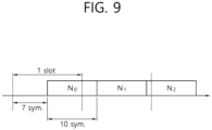
- FIG. 9 illustrates an example in which PUSCH is transmitted based on PUSCH repetition type B.
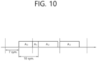
- FIG. 10 illustrates another example in which PUSCH is transmitted based on PUSCH repetition type B.
- repetition is performed in units of a symbol length in which an actual PUSCH is transmitted. That is, when the PUSCH is transmitted in 10 symbols as shown in FIG. 9 , PUSCH repetition is performed in units of 10 consecutive symbols. Repetition for determining PUSCH repetition transmission time resources without considering slot boundaries, invalid symbols, etc. is called nominal repetition. However, in case of actual PUSCH repetition, one PUSCH cannot be transmitted on a slot boundary. When the PUSCH transmission includes a slot boundary, two actual repetitions are performed across the slot boundary as shown in FIG. 10 . In addition, one PUSCH transmission can be performed only through consecutive symbols.
- actual repetitions are configured using consecutive symbols with the invalid symbol as a boundary. For example, if symbols #0 to #9 constitute one nominal repetition and symbols #3 to #5 are invalid symbols, i) symbols #0 to #2 and ii) symbols #6 to #9, excluding invalid symbols, each constitute one actual repetition.
- a symbol (e.g., a downlink symbol indicated by DCI format 2_0) that cannot be used for PUSCH transmission is included in one actual repetition resource, the actual repetition transmission is dropped and not performed.
- the UE may be configured with a frequency hopping by higher layer parameters.
- the frequency hopping mode for PUSCH transmission configured in type 2 follows the configuration of the active DCI format.
- One of two frequency hopping modes can be set:
- new service types such as extended reality (XR), AI-based services, and selfdriving cars are emerging, which are characterized by dynamically changing traffic in both DL and UL directions and low latency requirements for packet delivery.
- traffic load will increase explosively to support these various new use cases.
- the existing semi-static or dynamic TDD UL/DL configuration has limitations such as transmission time delay and interference between operators.
- Existing FDD schemes have limitations in terms of efficient frequency resource utilization for DL/UL directions.
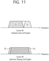
- FIG. 11 schematically illustrates an example of SB-FD and SS-FD.
- SB-FD subband-wise full duplex
- SS-FD spectrum-sharing full duplex
- FIG. 6 transmission and reception of DL and UL are performed using different frequency resources in the same carrier. That is, DL and UL have different frequency resources for the same time resource.
- transmission and reception of DL and UL are performed through the same frequency resource or overlapped frequency resources in the same carrier. That is, DL and UL may have the same or overlapping frequency resources for the same time resource.
- This full-duplex operation may be used in combination with a conventional half-duplex operation.
- a conventional half-duplex-based TDD operation only some time resources can be used for full-duplex operation.
- An SB-FD or SS-FD operation may be performed on a time resource for performing a full duplex operation.
- FIG. 12 schematically illustrates an example in which time resources operating in half duplex (HD) and time resources operating in full duplex (FD) such as SB-FD or SS-FD coexist.
- HD half duplex
- FD full duplex
- some time resources operate in SB-FD and the remaining time resources operate in HD.
- some time resources operate in SS-FD and the remaining time resources operate in HD.
- the unit of time resource may be, for example, a slot or a symbol.
- some frequency resources are used as DL resources and some frequency resources are used as UL resources. Between DL and UL frequency resources, there may be a guard sub-band (or guard frequency resource or guard subcarrier(s)) that is not used in both DL and UL and becomes empty.
- time resources operating with SF-FD all frequency resources can be used for both DL and UL.
- some frequency resources at one or both ends of the carrier may not be used for DL and/or UL in order to reduce the influence of interference from other adjacent carriers (i.e. ACI (adjacent carrier interference)). That is, one or both ends of the carrier may be used as a guard band that is not used for both DL and UL.
- ACI adjacent carrier interference
- one or both ends of the carrier may be used only for DL transmission.
- a frequency resource operating in DL among all frequency resources in time resources operating in FD is referred to as a DL sub-band
- a frequency resource operating in UL is referred to as a UL sub-band.
- the full duplex operation can be performed both in terms of the gNB and the UE. That is, both the gNB and the UE can simultaneously perform transmission and reception of DL and UL using the same or different frequency resources in the same time resource.
- the gNB may perform full-duplex operation, and the UE may perform half-duplex operation.
- the gNB may transmit/receive DL and UL at the same time using the same or different frequency resources in the same time resource, but the UE performs only DL reception or UL transmission in a specific time resource. In this case, the gNB performs full duplex operation by performing DL transmission and UL reception with different UEs at the same time.
- the scrambling sequence applied to the PUSCH changes according to the slot/subframe index in which the PUSCH is transmitted, but in NR, the scrambling sequence applied to the PUSCH is not affected by the slot index. That is, if the values of n RNTI and n ID are the same, the same scrambling sequence is applied to PUSCHs transmitted in different slots.
- the same n RNTI and n ID values are applied for a scrambling sequence between PUSCH repetitions transmitted in different slots. Therefore, the same scrambling sequence is applied between PUSCH repetitions.
- the same coded bit should be transmitted between PUSCH repetitions.
- the same RV value should be applied between PUSCH repetitions so that the same coded bits are transmitted.
- the same resource element (RE) resources are used by using the same scrambling sequence for the same coded bits. Such transmission may cause a problem of giving neighboring cells the same interference during the PUSCH repetition period.
- the content of this specification is described from the viewpoint of transmission of PUSCH, but the content of this specification includes not only PUSCH but also transmission of other channels such as PUCCH, PDSCH, and PDCCH.
- FIG. 13 shows an example of processing of a UL-SCH transport block. Specifically, FIG. 13 illustrates an example of a process from generation of a UL-SCH transport block, which is an information bit transmitted through a PUSCH, to mapping to a physical resource through which the PUSCH is transmitted.
- the UE generates coded bits of the UL-SCH through a coded bit generation process using the UL-SCH transport block.
- the coded bit generation process may include, for example, transport block CRC attachment, code block segmentation and code block CRC attachment, channel coding, rate matching, code block concatenation, data and control multiplexing, and the like in the NR standard.
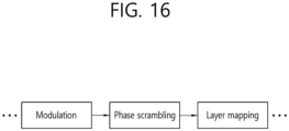
- the coded bits of these UL-SCHs are mapped to physical resources through a process of scrambling, modulation, layer mapping, transform precoding, and precoding.
- the same scrambling sequence is applied to the slots where PUSCH repetitions are performed, which may not provide inter-cell interference randomization.
- the inter-cell interference problem may be further increased.
- an operation of differently applying scrambling according to time intervals while PUSCH repetition is performed is required.
- a scrambling sequence applied to coded bits transmitted through the PUSCH may be changed according to time units.
- a scrambling sequence applied to the PUSCH may be different for each slot or slot group in which the PUSCH is transmitted.
- the value of c init for determining the scrambling sequence may be determined differently according to a slot index through which a PUSCH is transmitted or (slot index mod X).
- the scrambling sequence be changed as follows.
- c init n RNTI ⁇ 2 15 + n ID
- the value of conventional c init is determined dependently on n RNTI and n ID .
- n ID consists of 10 bits, so currently values in the [2 10 , 2 15 -1] range are not used as c init .
- a generic pseudo-random sequence may be defined as a length-31 Gold sequence.
- An output sequence c(n) of length M PN can be defined as below equation.
- n is 0, 1, ..., M PN -1.
- Nc 1600
- the initialization of the second m-sequence x 2 (n) can be expressed as the following equation together with values according to the application of the sequence.
- Equation 3 the value of c ini can be determined dependently on n RNTI , n ID , and a new parameter (hereafter referred to as an index). New parameters can contribute to randomization.
- c init can be defined as the following equation, and the index value can be applied differently depending on the time range.
- the index may have a value within the range of [0, 2 5 -1].
- n ID (n ID ⁇ ⁇ 0, 1, ..., 1023 ⁇ ) may equal the higher-layer parameter dataScramblingIdentityPUSCH if configured and the RNTI equals the C-RNTI, MCS-C-RNTI, SP-CSI-RNTI or CS-RNTI, and the transmission is not scheduled using DCI format 0_0 in a common search space.
- n ID may equal the higher-layer parameter msgA-dataScramblingIdentity if configured and the PUSCH transmission is triggered by a Type-2 random access procedure.
- n ID N cell ID .
- n RNTI may equal the RA-RNTI for msgA and otherwise corresponds to the RNTI associated with the PUSCH transmission.
- the index value may mean at least one of the following.
- the index value may mean a slot index, more specifically, a slot index within a frame. Considering the case where the slot index is greater than 2 5 -1, the value of the index may be equal to (slot index mod 2 5 ).
- the index value may mean floor (slot index/X). This is to make the scrambling sequence applied to the PUSCH different according to the slot group. More specifically, the slot index may mean a slot index within a frame. Considering the case where the slot index is greater than 2 5 -1, the value of the index may be equal to (floor(slot index/X) mod 2 5 ).
- the index value means the repetition number of the currently transmitted PUSCH. That is, when PUSCH repetitions are performed a total of N times, the index may mean n for the n-th (n is an integer less than or equal to N) PUSCH repetition.
- the index in the PUSCH transmission at the nth slot can mean n for the entire N slots over which the PUSCH repetition is performed.
- the index at the nth nominal repetition means n for all N nominal repetitions in which PUSCH repetitions are performed.
- the index at the n'th actual repetition may mean n'.
- the receiver may not be able to receive the repetitively transmitted PUSCH by symbol/RE-level combining.
- Quadrature Amplitude Modulation such as 16 QAM, 64 QAM, etc.
- the receiver may not be able to perform combining between modulated symbols of different PUSCH repetitions because not only the phase of the modulated symbols but also their magnitude can be changed according to the scrambling sequence.
- phase-shift keying PSK
- FIG. 14 shows an example of a constellation diagram of BPSK, QPSK, and 8-PSK.
- FIG. 15 shows an example of a constellation of 16 QAM.
- this scrambling method can be limitedly applied when PSK-based modulation is used.
- the amount of information bits for coverage enhancement since it is effective to reduce the amount of information bits for coverage enhancement, it may be limited to apply only a PSK-based modulation when PUSCH repetition is performed. This may mean that when M bits constitute one modulated symbol, M is limited to a value of 8 or less.
- a modulated symbol value may vary according to a scrambling sequence. Accordingly, combining between repeatedly transmitted modulated symbols may not be performed, especially when QAM-based modulation is used. To solve this problem, the following phase scrambling method can be used.
- modulated symbol level phase scrambling can mean the following.
- K modulated symbols d(0), d(1), d(2), ..., d(K-1) can be generated.
- one modulated symbol d(i) can be generated with M bits of b(M*i), b(M ⁇ i+1), b(M*i+2), ..., b(M ⁇ i+M-1).
- the modulation mapper receives binary digits 0 or 1, and can output/generate complex-valued modulation symbols according to a modulation mapping method as in at least one of methods 1) to 6) below.
- bit b(i) may be mapped to a complex-valued modulation symbol d(i) according to the following equation.
- d i e j ⁇ 2 i mod 2 2 1 ⁇ 2 b i + j 1 ⁇ 2 b i
- bit b(i) may be mapped to a complex-valued modulation symbol d(i) according to the following equation.
- d i 1 2 1 ⁇ 2 b i + j 1 ⁇ 2 b i
- bit pair b(2i), b(2i+1) may be mapped to a complex-valued modulation symbol d(i) according to the following equation.
- d i 1 2 1 ⁇ 2 b 2 i + j 1 ⁇ 2 b 2 i + 1
- the quadruplets of bits b(4i), b(4i+1), b(4i+2), and b(4i+3) may be mapped to a complex-valued modulation symbol d(i) according to the following equation.
- d i 1 10 1 ⁇ 2 b 4 i 2 ⁇ 1 ⁇ 2 b 4 i + 2 + j 1 ⁇ 2 b 4 i + 1 2 ⁇ 1 ⁇ 2 b 4 i + 3
- d(i) 1 42 1 ⁇ 2 b 6 i 4 ⁇ 1 ⁇ 2 b 6 i + 2 2 ⁇ 1 ⁇ 2 b 6 i + 4 + j 1 ⁇ 2 b 6 i + 1 4 ⁇ 1 ⁇ 2 b 6 i + 3 2 ⁇ 1 ⁇ 2 b 6 i + 5
- octuplets of bits b(8i), b(8i+1), b(8i+2), b(8i+3), b(8i+4), b(8i+5 ), b(8i+6), and b(8i+7) may be mapped to a complex-valued modulation symbol d(i) according to the following equation.
- d i 1 170 1 ⁇ 2 b 8 i 8 ⁇ 1 ⁇ 2 b 8 i + 2 4 ⁇ 1 ⁇ 2 b 8 i + 4 2 ⁇ 1 ⁇ 2 b 8 i + 6 + j 1 ⁇ 2 b 8 i + 1 8 ⁇ 1 ⁇ 2 b 8 i + 3 4 ⁇ 1 ⁇ 2 b 8 i + 5 2 ⁇ 1 ⁇ 2 b 8 i + 7
- i 0, 1, ..., M layer symb -1
- ⁇ is the number of layers
- M layer symb may be the number of modulation symbols per layer.
- a phase scrambling process may be added between modulation and layer mapping or between layer mapping and transform precoding.
- FIG. 16 shows an example in which a phase scrambling process is added between modulation and layer mapping processes.
- FIG. 17 illustrates an example in which a phase scrambling process is added between layer mapping and transform precoding.
- s(i) may be as follows.
- s(i) may have one of 1, -1, j, and -j. Characteristically, this method may be limited to a case in which modulation with a modulation order M of 2 or more is applied.
- s(i) may have a value of 1 or -1. Characteristically, this method can be limited to the case of applying modulation with a modulation order M of 1.
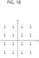
- FIG. 18 shows an example of 16 values of modulated symbols that can be mapped when 16QAM is applied.
- s(i) has a value of 1, -1, j, or j
- d'(i) has one of the values indicated by the same alphabet as the value of d(i).
- d(i) has a value denoted by A
- the value of d(i) has one of four values denoted by A.
- d'(i) has one value among four mapping values having the same magnitude as the value of d(i) and different phases according to the value of s(i). Therefore, even when QAM-based modulation is used, the receiver can perform combining between modulated symbols of different PUSCH repetitions by appropriately changing the phase of the received symbol.
- the method of performing phase scrambling on the modulated symbols before the transform precoding which is a DFT process, may not perform the operation of combining repeated symbols before performing equalization at the receiving end. For this operation, phase scrambling may be performed on symbols after transform precoding.
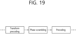
- FIG. 19 illustrates an example in which a phase scrambling process is added between transform precoding and precoding processes.
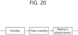
- FIG. 20 illustrates an example in which a phase scrambling process is added between precoding and virtual resource block mapping processes.
- scrambling should be performed so that only the phase of complex symbols is changed. That is, s(i) may have a value that changes only the phase of the modulated symbol.
- the value of s(i) within a PUSCH transmission or within a slot may be determined as follows.
- s(i) may have a different value depending on i. That is, s(i) having a different value for each complex symbol may be multiplied. This may mean that s(i) having a different value is multiplied for each RE position where the complex symbol is transmitted.
- s(i) may have the same value within a slot in which a PUSCH is transmitted or within one PUSCH transmission. That is, within a slot or for one PUSCH transmission, s(i) may have the same value for all i.
- s(i) may have the following values.
- s(i) may have one of 1, -1, j, and -j. Characteristically, this can be applied to a method in which a PAPR issue does not occur by applying the same phase scrambling value in the same OFDM symbol or same slot among the above methods.
- s(i) may have a value of a Zadoff-Chu (ZC) sequence. That is, s(0), s(i), ..., s(M-1) may have the form of a ZC sequence.
- ZC Zadoff-Chu
- s(i) may have different values over time as follows.
- (Alternative a) s(i) may have a different value according to a slot index through which PUSCH is transmitted or a value of floor(slot index/X). That is, for the same value of i, the value of s(i) may have a different value according to the slot index in which the PUSCH is transmitted or floor (slot index/X).
- (Alternative b) s(i) may have a different value according to the repetition number of the currently transmitted PUSCH. That is, when performing all N PUSCH repetitions, s(i) may be determined differently for each PUSCH repetition. When PUSCH transmission is performed using PUSCH repetition type B (i.e., symbol-based repetition), s(i) may have a different value according to nominal PUSCH repetitions or actual PUSCH repetitions.
- phase scrambling can be applied independently of scrambling performed on existing coded bits. Alternatively, when phase scrambling is applied, scrambling performed on the existing coded bits may not be performed.
- phase scrambling can be limitedly applied when QAM-based modulation is used or when the modulation order is 16 or more.
- method A when PSK-based modulation is applied (or when the modulation order M is 8 or less), method A is applied, and when QAM-based modulation is applied (or when the modulation order M is greater than 8), method B may be applied.
- the UE can determine whether bit-level scrambling and/or phase scrambling are applied through the following method.
- Method 1 It may be indicated that bit level scrambling or phase scrambling is applied for PUSCH transmission through higher layer signaling or DCI indication.
- Method 2 When PUSCH transmission time resources are configured to perform PUSCH repetitions, including time resources (e.g., slots) for performing full duplex (SS-FD, SB-FD) operations, the UE may determine that bit-level scrambling or phase scrambling is applied for transmission of the PUSCH.
- time resources e.g., slots
- SB-FD full duplex
- Method 3 When a full duplex (SS-FD, SB-FD) operation is performed in a serving cell transmitting a PUSCH using PUSCH repetition, or, if time resources (e.g., slots) to perform full duplex (SS-FD, SB-FD) operation is included, the UE may determine that bit-level scrambling or phase scrambling is applied for transmission of the PUSCH.
- time resources e.g., slots
- the UE may perform PUSCH repetition by applying the corresponding scrambling scheme, and otherwise may perform PUSCH repetition by applying the conventional scrambling scheme.
- FIG. 21 is a flowchart of an example of a method for performing repeated PUSCH transmissions by a UE according to some implementations of the present specification.
- the UE performs scrambling on coded bits (S2110).
- the scrambling may include scrambling based on Method A and Method B described above.
- the coded bits may be generated by the UE performing channel coding on the transport block.
- the UE transmits the first bit and the second bit generated based on the scrambling to the base station through the PUSCH (S2120).
- the first bit is transmitted through a first time resource
- the second bit is transmitted through a second time resource.
- the first bit and the second bit may be generated by performing scrambling independently on the coded bit. That is, the first bit and the second bit may be generated by independently performing scrambling on the same transport block.
- the first bit may be generated based on a first scrambling sequence
- the second bit may be generated based on a second scrambling sequence.
- the first scrambling sequence may be generated based on the index of the first time resource
- the second scrambling sequence may be generated based on the index of the second time resource.
- the UE may generate a scrambled bit based on the scrambling and perform phase scrambling on the scrambled bit to generate a first bit and a second bit. That is, the phase of the first bit may be different from the phase of the second bit.
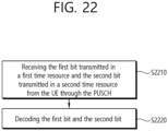
- FIG. 22 is a flowchart of an example of a method of repeatedly receiving a PUSCH by a base station according to some implementations of the present specification.
- the base station receives the first bit transmitted in a first time resource and the second bit transmitted in a second time resource from the UE through the PUSCH (S2210).
- the base station decodes the first bit and the second bit (S2220).
- the first bit and the second bit may be generated by performing scrambling independently on the coded bit. That is, the first bit and the second bit may be generated by independently performing scrambling on the same transport block.
- the first bit may be generated based on a first scrambling sequence
- the second bit may be generated based on a second scrambling sequence.
- the first scrambling sequence may be generated based on the index of the first time resource
- the second scrambling sequence may be generated based on the index of the second time resource.
- the UE may generate a scrambled bit based on the scrambling and perform phase scrambling on the scrambled bit to generate a first bit and a second bit. That is, the phase of the first bit may be different from the phase of the second bit.
- the methods proposed in this specification can be performed not only by a UE, but also by at least one computer readable medium containing instructions based on being executed by at least one processor and a device (apparatus) set to control a UE and including one or more processors and one or more memories operably connected by the one or more processors and storing instructions, wherein the one or more processors execute the instructions to perform the methods proposed herein.
- a device apparatus
- the one or more processors execute the instructions to perform the methods proposed herein.
- an operation by a base station corresponding to an operation performed by a UE can be considered.
- FIG. 23 illustrates a communication system 1 applied to the present disclosure.
- the communication system 1 applied to the present disclosure includes a wireless device, a base station, and a network.
- the wireless device refers to a device that performs communication using a wireless access technology (e.g., 5G NR (New RAT), LTE (Long Term Evolution)), and may be referred to as a communication/wireless/5G device.
- a wireless access technology e.g., 5G NR (New RAT), LTE (Long Term Evolution)
- the wireless device may include a robot 100a, a vehicle 100b-1, 100b-2, an extended Reality (XR) device 100c, a hand-held device 100d, and a home appliance 100e. ), an Internet of Things (IoT) device 100f, and an AI device/server 400.
- a wireless access technology e.g., 5G NR (New RAT), LTE (Long Term Evolution)
- the wireless device may include a robot 100a, a vehicle 100b-1, 100b-2, an extended Reality (X
- the vehicle may include a vehicle equipped with a wireless communication function, an autonomous driving vehicle, a vehicle capable of performing inter-vehicle communication, and the like.
- the vehicle may include an Unmanned Aerial Vehicle (UAV) (e.g., a drone).
- UAV Unmanned Aerial Vehicle
- XR devices include AR (Augmented Reality)/VR (Virtual Reality)/MR (Mixed Reality) devices, and it may be implemented in the form of a Head-Mounted Device (HMD), a Head-Up Display (HUD) provided in a vehicle, a television, a smartphone, a computer, a wearable device, a home appliance, a digital signage, a vehicle, a robot, and the like.
- HMD Head-Mounted Device
- HUD Head-Up Display
- the portable device may include a smart phone, a smart pad, a wearable device (e.g., a smart watch, smart glasses), a computer (e.g., a laptop computer), and the like.
- Home appliances may include a TV, a refrigerator, a washing machine, and the like.
- the IoT device may include a sensor, a smart meter, and the like.
- the base station and the network may be implemented as a wireless device, and a specific wireless device 200a may operate as a base station/network node to other wireless devices.
- the wireless communication technology implemented in the wireless device of the present specification may include Narrowband Internet of Things for low power communication as well as LTE, NR, and 6G.
- NB-IoT technology may be an example of Low Power Wide Area Network (LPWAN) technology, and may be implemented in standards such as LTE Cat NB1 and/or LTE Cat NB2, without limitation.
- LPWAN Low Power Wide Area Network
- the wireless communication technology implemented in the wireless devices of this disclosure may perform communications based on LTE-M technology.
- LTE-M technology may be an example of LPWAN technology and may be referred to by various names, such as enhanced Machine Type Communication (eMTC).
- eMTC enhanced Machine Type Communication
- LTE-M technology may be implemented in at least one of various specifications, such as 1) LTE CAT 0, 2) LTE Cat M1, 3) LTE Cat M2, 4) LTE non-Bandwidth Limited (non-BL), 5) LTE-MTC, 6) LTE Machine Type Communication, and/or 7) LTE M, and is not limited to the above designations.
- the wireless communication technologies implemented in the wireless devices of this disclosure may include at least one of ZigBee, Bluetooth, and Low Power Wide Area Network (LPWAN), which contemplate low power communication, and are not limited to the designations described above.
- ZigBee technology can create personal area networks (PANs) for small, low-power digital communications based on various specifications, such as IEEE 802.15.4, and may be referred to by various names.
- PANs personal area networks
- the wireless devices 100a-100f may be connected to the network 300 via the base station 200.
- the wireless devices 100a-100f may be equipped with artificial intelligence (AI) technology, and the wireless devices 100a-100f may be connected to an AI server 400 via the network 300.
- the network 300 may be organized using a 3G network, a 4G (e.g., LTE) network, or a 5G (e.g., NR) network, or the like.
- the wireless devices 100a-100f may communicate with each other via the base station 200/network 300, but may also communicate directly (e.g., sidelink communication) without going through the base station/network.
- vehicles 100b-1, 100b-2 may communicate directly (e.g., vehicle to vehicle (V2V)/vehicle to everything (V2X) communication).
- IoT devices e.g., sensors
- IoT devices may communicate directly with other IoT devices (e.g., sensors) or other wireless devices 100a-100f.
- Wireless communications/connections 150a, 150b, 150c may be established between wireless devices 100a-100f, base station 200, and base station 200.
- the wireless communications/connections may be accomplished via various wireless access technologies (e.g., 5G NR), such as uplink/downlink communications 150a, sidelink communications 150b (or, D2D communications), and base station-to-base station communications 150c (e.g., relay, integrated access backhaul (IAB)).
- the wireless communications/connections 150a, 150b, 150c may enable the wireless device and the base station/the wireless device, and the base station and the wireless device to transmit/receive wireless signals to each other.
- the wireless communications/connections 150a, 150b, 150c may transmit/receive signals via various physical channels.
- various configuration information setting processes for transmitting/receiving wireless signals various signal processing processes (e.g., channel encoding/decoding, modulation/demodulation, resource mapping/demapping, etc.), resource allocation processes, etc.
- signal processing processes e.g., channel encoding/decoding, modulation/demodulation, resource mapping/demapping, etc.
- resource allocation processes etc.
- FIG. 24 illustrates a wireless device applicable to the present disclosure.
- the first wireless device 100 and the second wireless device 200 may transmit and receive wireless signals through various wireless access technologies (e.g., LTE, NR).
- ⁇ first wireless device 100, second wireless device 200 ⁇ may correspond to ⁇ wireless device 100x, base station 200 ⁇ and/or ⁇ wireless device 100x, wireless device 100x ⁇ of FIG. 23 .
- the first wireless device 100 may include one or more processors 102 and one or more memories 104 and additionally further include one or more transceivers 106 and/or one or more antennas 108.
- the processors 102 may control the memory 104 and/or the transceivers 106 and may be configured to implement the descriptions, functions, procedures, proposals, methods, and/or operational flowcharts disclosed in this document.
- the processors 102 may process information within the memory 104 to generate first information/signals and then transmit radio signals including the first information/signals through the transceivers 106.
- the processor 102 may receive radio signals including second information/signals through the transceiver 106 and then store information obtained by processing the second information/signals in the memory 104.
- the memory 104 may be connected to the processory102 and may store a variety of information related to operations of the processor 102.
- the memory 104 may store software code including commands for performing a part or the entirety of processes controlled by the processor 102 or for performing the descriptions, functions, procedures, proposals, methods, and/or operational flowcharts disclosed in this document.
- the processor 102 and the memory 104 may be a part of a communication modem/circuit/chip designed to implement RAT (e.g., LTE or NR).
- the transceiver 106 may be connected to the processor 102 and transmit and/or receive radio signals through one or more antennas 108.
- the transceiver 106 may include a transmitter and/or a receiver.
- the transceiver 106 may be interchangeably used with a radio frequency (RF) unit.
- the wireless device may represent a communication modem/circuit/chip.
- the second wireless device 200 may include one or more processors 202 and one or more memories 204 and additionally further include one or more transceivers 206 and/or one or more antennas 208.
- the processor 202 may control the memory 204 and/or the transceiver 206 and may be configured to implement the descriptions, functions, procedures, proposals, methods, and/or operational flowcharts disclosed in this document.
- the processor 202 may process information within the memory 204 to generate third information/signals and then transmit radio signals including the third information/signals through the transceiver 206.
- the processor 202 may receive radio signals including fourth information/signals through the transceiver 106 and then store information obtained by processing the fourth information/signals in the memory 204.
- the memory 204 may be connected to the processor 202 and may store a variety of information related to operations of the processor 202.
- the memory 204 may store software code including commands for performing a part or the entirety of processes controlled by the processor 202 or for performing the descriptions, functions, procedures, proposals, methods, and/or operational flowcharts disclosed in this document.
- the processor 202 and the memory 204 may be a part of a communication modem/circuit/chip designed to implement RAT (e.g., LTE or NR).
- the transceiver 206 may be connected to the processor 202 and transmit and/or receive radio signals through one or more antennas 208.
- the transceiver 206 may include a transmitter and/or a receiver.
- the transceiver 206 may be interchangeably used with an RF unit.
- the wireless device may represent a communication modem/circuit/chip.
- One or more protocol layers may be implemented by, without being limited to, one or more processors 102 and 202.
- the one or more processors 102 and 202 may implement one or more layers (e.g., functional layers such as PHY, MAC, RLC, PDCP, RRC, and SDAP).
- the one or more processors 102 and 202 may generate one or more Protocol Data Units (PDUs) and/or one or more Service Data Unit (SDUs) according to the descriptions, functions, procedures, proposals, methods, and/or operational flowcharts disclosed in this document.
- PDUs Protocol Data Units
- SDUs Service Data Unit
- the one or more processors 102 and 202 may generate messages, control information, data, or information according to the descriptions, functions, procedures, proposals, methods, and/or operational flowcharts disclosed in this document.
- the one or more processors 102 and 202 may generate signals (e.g., baseband signals) including PDUs, SDUs, messages, control information, data, or information according to the descriptions, functions, procedures, proposals, methods, and/or operational flowcharts disclosed in this document and provide the generated signals to the one or more transceivers 106 and 206.
- the one or more processors 102 and 202 may receive the signals (e.g., baseband signals) from the one or more transceivers 106 and 206 and acquire the PDUs, SDUs, messages, control information, data, or information according to the descriptions, functions, procedures, proposals, methods, and/or operational flowcharts disclosed in this document.
- signals e.g., baseband signals
- the one or more processors 102 and 202 may be referred to as controllers, microcontrollers, microprocessors, or microcomputers.
- the one or more processors 102 and 202 may be implemented by hardware, firmware, software, or a combination thereof.
- ASICs Application Specific Integrated Circuits
- DSPs Digital Signal Processors
- DSPDs Digital Signal Processing Devices
- PLDs Programmable Logic Devices
- FPGAs Field Programmable Gate Arrays
- the descriptions, functions, procedures, proposals, methods, and/or operational flowcharts disclosed in this document may be implemented using firmware or software and the firmware or software may be configured to include the modules, procedures, or functions.
- Firmware or software configured to perform the descriptions, functions, procedures, proposals, methods, and/or operational flowcharts disclosed in this document may be included in the one or more processors 102 and 202 or stored in the one or more memories 104 and 204 so as to be driven by the one or more processors 102 and 202.
- the descriptions, functions, procedures, proposals, methods, and/or operational flowcharts disclosed in this document may be implemented using firmware or software in the form of code, commands, and/or a set of commands.
- the one or more memories 104 and 204 may be connected to the one or more processors 102 and 202 and store various types of data, signals, messages, information, programs, code, instructions, and/or commands.
- the one or more memories 104 and 204 may be configured by Read-Only Memories (ROMs), Random Access Memories (RAMs), Electrically Erasable Programmable Read-Only Memories (EPROMs), flash memories, hard drives, registers, cash memories, computer-readable storage media, and/or combinations thereof.
- the one or more memories 104 and 204 may be located at the interior and/or exterior of the one or more processors 102 and 202.
- the one or more memories 104 and 204 may be connected to the one or more processors 102 and 202 through various technologies such as wired or wireless connection.
- the one or more transceivers 106 and 206 may transmit user data, control information, and/or radio signals/channels, mentioned in the methods and/or operational flowcharts of this document, to one or more other devices.
- the one or more transceivers 106 and 206 may receive user data, control information, and/or radio signals/channels, mentioned in the descriptions, functions, procedures, proposals, methods, and/or operational flowcharts disclosed in this document, from one or more other devices.
- the one or more transceivers 106 and 206 may be connected to the one or more processors 102 and 202 and transmit and receive radio signals.
- the one or more processors 102 and 202 may perform control so that the one or more transceivers 106 and 206 may transmit user data, control information, or radio signals to one or more other devices.
- the one or more processors 102 and 202 may perform control so that the one or more transceivers 106 and 206 may receive user data, control information, or radio signals from one or more other devices.
- the one or more transceivers 106 and 206 may be connected to the one or more antennas 108 and 208 and the one or more transceivers 106 and 206 may be configured to transmit and receive user data, control information, and/or radio signals/channels, mentioned in the descriptions, functions, procedures, proposals, methods, and/or operational flowcharts disclosed in this document, through the one or more antennas 108 and 208.
- the one or more antennas may be a plurality of physical antennas or a plurality of logical antennas (e.g., antenna ports).
- the one or more transceivers 106 and 206 may convert received radio signals/channels etc.
- the one or more transceivers 106 and 206 may convert the user data, control information, radio signals/channels, etc. processed using the one or more processors 102 and 202 from the base band signals into the RF band signals.
- the one or more transceivers 106 and 206 may include (analog) oscillators and/or filters.
- FIG. 25 exemplifies a signal processing circuit for a transmission signal.
- a signal processing circuit 1000 includes a scrambler 1010, a modulator 1020, a layer mapper 1030, a precoder 1040, a resource mapper 1050, and a signal generator 1060.
- the operations/functions of FIG. 25 may be performed in the processors 102 and 202 and/or the transceivers 106 and 206 of FIG. 24 but are not limited thereto.
- the hardware elements of FIG. 25 may be implemented in the processors 102 and 202 and/or the transceivers 106 and 206 of FIG. 24 .
- blocks 1010 to 1060 may be implemented in the processors 102 and 202 of FIG. 24 .
- blocks 1010 to 1050 may be implemented in the processors 102 and 202 of FIG. 24
- block 1060 may be implemented in the transceivers 106 and 206 of FIG. 24 .
- a codeword may be converted into a wireless signal through the signal processing circuit 1000 of FIG. 25 .
- the codeword is an encoded bit sequence of an information block.
- the information block may include a transport block (e.g., a UL-SCH transport block or a DL-SCH transport block).
- the wireless signal may be transmitted through various physical channels (e.g., PUSCH or PDSCH).
- the codeword may be converted into a scrambled bit sequence by the scrambler 1010.
- the scramble sequence used for scrambling is generated based on an initialization value, and the initialization value may include ID information of a wireless device.
- the scrambled bit sequence may be modulated by the modulator 1020 into a modulation symbol sequence.
- the modulation scheme may include pi/2-binary phase shift keying (pi/2-BPSK), m-phase shift keying (m-PSK), m-quadrature amplitude modulation (m-QAM), and the like.
- the complex modulation symbol sequence may be mapped to one or more transport layers by the layer mapper 1030.
- the modulation symbols of each transport layer may be mapped to the corresponding antenna port(s) by the precoder 1040 (precoding).
- An output z of the precoder 1040 may be obtained by multiplying an output y of the layer mapper 1030 by an N*M precoding matrix W.
- N is the number of antenna ports and M is the number of transmission layers.
- the precoder 1040 may perform precoding after performing transform precoding (e.g., DFT transform) on complex modulation symbols. Also, the precoder 1040 may perform precoding without performing transform precoding.
- the resource mapper 1050 may map modulation symbols of each antenna port to a time-frequency resource.
- the time-frequency resource may include a plurality of symbols (e.g., CP-OFDMA symbols or DFT-s-OFDMA symbols) in a time domain and may include a plurality of subcarriers in a frequency domain.
- the signal generator 1060 may generate a wireless signal from the mapped modulation symbols, and the generated wireless signal may be transmitted to another device through each antenna. To this end, the signal generator 1060 may include an inverse fast Fourier transform (IFFT) module, a cyclic prefix (CP) inserter, a digital-to-analog converter (DAC), a frequency uplink converter, and the like.
- IFFT inverse fast Fourier transform
- CP cyclic prefix
- DAC digital-to-analog converter
- a signal processing process for a received signal in the wireless device may be configured as the reverse of the signal processing process (1010 to 1060) of FIG. 25 .
- a wireless device e.g., 100 or 200 in FIG. 24
- the received wireless signal may be converted into a baseband signal through a signal restorer.
- the signal restorer may include a frequency downlink converter, an analog-to-digital converter (ADC), a CP canceller, and a fast Fourier transform (FFT) module.
- ADC analog-to-digital converter
- FFT fast Fourier transform
- the baseband signal may be restored into a codeword through a resource de-mapper process, a postcoding process, a demodulation process, and a de-scramble process.
- the codeword may be restored to an original information block through decoding.
- a signal processing circuit (not shown) for a received signal may include a signal restorer, a resource demapper, a postcoder, a demodulator, a descrambler, and a decoder.
- FIG. 26 shows another example of a wireless device applied to the present disclosure.
- the wireless device can be implemented in various forms according to use-examples/services.
- wireless devices (100, 200) may correspond to the wireless devices (100, 200) of FIG. 24 and may be configured by various elements, components, units/portions, and/or modules.
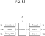
- each of the wireless devices (100, 200) may include a communication unit (110), a control unit (120), a memory unit (130), and additional components (140).
- the communication unit may include a communication circuit (112) and transceiver(s) (114).
- the communication circuit (112) may include the one or more processors (102, 202) and/or the one or more memories (104, 204) of FIG. 24 .
- the transceiver(s) (114) may include the one or more transceivers (106, 206) and/or the one or more antennas (108, 208) of FIG. 24 .
- the control unit (120) is electrically connected to the communication unit (110), the memory (130), and the additional components (140) and controls overall operation of the wireless devices.
- the control unit (120) may control an electric/mechanical operation of the wireless device based on programs/code/instructions/information stored in the memory unit (130).
- the control unit (120) may transmit the information stored in the memory unit (130) to the exterior (e.g., other communication devices) via the communication unit (110) through a wireless/wired interface or store, in the memory unit (130), information received through the wireless/wired interface from the exterior (e.g., other communication devices) via the communication unit (110).
- the additional components (140) may be variously configured according to types of wireless devices.
- the additional components (140) may include at least one of a power unit/battery, input/output (I/O) unit, a driving unit, and a computing unit.
- the wireless device may be implemented in the form of, without being limited to, the robot (100a of FIG. 23 ), the vehicles (100b-1, 100b-2 of FIG. 23 ), the XR device (100c of FIG. 23 ), the hand-held device (100d of FIG. 23 ), the home appliance (100e of FIG. 23 ), the IoT device (100f of FIG.
- the wireless device may be used in a mobile or fixed place according to a usage-example/service.
- the entirety of the various elements, components, units/portions, and/or modules in the wireless devices (100, 200) may be connected to each other through a wired interface or at least a part thereof may be wirelessly connected through the communication unit (110).
- the control unit (120) and the communication unit (110) may be connected by wire and the control unit (120) and first units (e.g., 130, 140) may be wirelessly connected through the communication unit (110).
- Each element, component, unit/portion, and/or module within the wireless devices (100, 200) may further include one or more elements.
- the control unit (120) may be configured by a set of one or more processors.
- control unit (120) may be configured by a set of a communication control processor, an application processor, an Electronic Control Unit (ECU), a graphical processing unit, and a memory control processor.
- the memory (130) may be configured by a Random Access Memory (RAM), a Dynamic RAM (DRAM), a Read Only Memory (ROM)), a flash memory, a volatile memory, a non-volatile memory, and/or a combination thereof.
- FIG. 26 An example of implementing FIG. 26 will be described in detail with reference to the drawings.
- FIG. 27 illustrates a portable device applied to the present disclosure.
- the portable device may include a smartphone, a smart pad, a wearable device (e.g., smart watch or smart glasses), a portable computer (e.g., a notebook), etc.
- the portable device may be referred to as a mobile station (MS), a user terminal (UT), a mobile subscriber station (MSS), a subscriber station (SS), an advanced mobile station (AMS), or a wireless terminal (WT).
- MS mobile station
- UT user terminal
- MSS mobile subscriber station
- SS subscriber station
- AMS advanced mobile station
- WT wireless terminal
- the portable device 100 may include an antenna unit 108, a communication unit 110, a controller 120, a memory unit 130, a power supply unit 140a, an interface unit 140b, and input/output unit 140c.
- the antenna unit 108 may be configured as a part of the communication unit 110.
- Blocks 110 to 130/140a to 140c correspond to blocks 110 to 130/140 of FIG. 26 , respectively.
- the communication unit 110 may transmit and receive signals (e.g., data, control signals, etc.) with other wireless devices and BSs.
- the controller 120 may perform various operations by controlling components of the portable device 100.
- the controller 120 may include an application processor (AP).
- the memory unit 130 may store data/parameters/programs/codes/commands required for driving the portable device 100. Also, the memory unit 130 may store input/output data/information, and the like.
- the power supply unit 140a supplies power to the portable device 100 and may include a wired/wireless charging circuit, a battery, and the like.
- the interface unit 140b may support connection between the portable device 100 and other external devices.
- the interface unit 140b may include various ports (e.g., audio input/output ports or video input/output ports) for connection with external devices.
- the input/output unit 140c may receive or output image information/signal, audio information/signal, data, and/or information input from a user.
- the input/output unit 140c may include a camera, a microphone, a user input unit, a display unit 140d, a speaker, and/or a haptic module.
- the input/output unit 140c acquires information/signals (e.g., touch, text, voice, image, or video) input from the user, and the acquired information/signals may be stored in the memory unit 130.
- the communication unit 110 may convert information/signals stored in the memory into wireless signals and may directly transmit the converted wireless signals to other wireless devices or to a BS.
- the communication unit 110 may restore the received wireless signal to the original information/signal.
- the restored information/signal may be stored in the memory unit 130 and then output in various forms (e.g., text, voice, image, video, or haptic) through the input/output unit 140c.
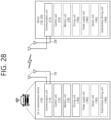
- FIG. 28 illustrates a vehicle or an autonomous vehicle applied to the present disclosure.
- a vehicle or an autonomous vehicle may be implemented as a moving robot, a vehicle, a train, a manned/unmanned aerial vehicle (AV), a ship, or the like.
- AV manned/unmanned aerial vehicle
- a vehicle or autonomous vehicle 100 includes an antenna unit 108, a communication unit 110, a control unit 120, a driving unit 140a, a power supply unit 140b, and a sensor unit 140c, and an autonomous driving unit 140d.
- the antenna unit 108 may be configured as a portion of the communication unit 110.
- Blocks 110/130/140a to 140d correspond to blocks 110/130/140 of FIG. 26 , respectively.
- the communication unit 110 may transmit and receive signals (e.g., data, control signals, etc.) with external devices such as other vehicles, base stations (BSs) (e.g. base station, roadside unit, etc.), and servers.
- the control unit 120 may perform various operations by controlling elements of the vehicle or the autonomous vehicle 100.
- the control unit 120 may include an electronic control unit (ECU).
- the driving unit 140a may cause the vehicle or the autonomous vehicle 100 to travel on the ground.
- the driving unit 140a may include an engine, a motor, a power train, a wheel, a brake, a steering device, and the like.
- the power supply unit 140b supplies power to the vehicle or the autonomous vehicle 100, and may include a wired/wireless charging circuit, a battery, and the like.
- the sensor unit 140c may obtain vehicle status, surrounding environment information, user information, and the like.
- the sensor unit 140c may include an inertial measurement unit (IMU) sensor, a collision sensor, a wheel sensor, a speed sensor, an inclination sensor, a weight detection sensor, a heading sensor, a position module, a vehicle forward/reverse sensor, a battery sensor, a fuel sensor, a tire sensor, a steering sensor, a temperature sensor, a humidity sensor, an ultrasonic sensor, an illuminance sensor, a pedal position sensor, etc.
- IMU inertial measurement unit
- the autonomous driving unit 140d may implement a technology of maintaining a driving lane, a technology of automatically adjusting a speed such as adaptive cruise control, a technology of automatically traveling along a predetermined route, and a technology of automatically setting a route and traveling when a destination is set.
- the communication unit 110 may receive map data, traffic information data, and the like from an external server.
- the autonomous driving unit 140d may generate an autonomous driving route and a driving plan based on the acquired data.
- the control unit 120 may control the driving unit 140a so that the vehicle or the autonomous vehicle 100 moves along the autonomous driving route according to the driving plan (e.g., speed/direction adjustment).
- the communication unit 110 may asynchronously/periodically acquire the latest traffic information data from an external server and may acquire surrounding traffic information data from surrounding vehicles.
- the sensor unit 140c may acquire vehicle state and surrounding environment information.
- the autonomous driving unit 140d may update the autonomous driving route and the driving plan based on newly acquired data/information.
- the communication unit 110 may transmit information on a vehicle location, an autonomous driving route, a driving plan, and the like to the external server.
- the external server may predict traffic information data in advance using AI technology or the like based on information collected from the vehicle or autonomous vehicles and may provide the predicted traffic information data to the vehicle or autonomous vehicles.
- FIG. 29 illustrates a vehicle applied to the present disclosure. Vehicles may also be implemented as means of transportation, trains, aircraft, and ships.
- the vehicle 100 may include a communication unit 110, a control unit 120, a memory unit 130, an input/output unit 140a, and a position measurement unit 140b.
- blocks 110 to 130/140a to 140d correspond to blocks 110 to 130/140 of FIG. 26 , respectively.
- the communication unit 110 may transmit and receive signals (e.g., data, control signals, etc.) with other vehicles or external devices such as a BS.
- the control unit 120 may perform various operations by controlling components of the vehicle 100.
- the memory unit 130 may store data/parameters/programs/codes/commands supporting various functions of the vehicle 100.
- the input/output unit 140a may output an AR/VR object based on information in the memory unit 130.
- the input/output unit 140a may include a HUD.
- the location measurement unit 140b may acquire location information of the vehicle 100.
- the location information may include absolute location information of the vehicle 100, location information within a driving line, acceleration information, location information with surrounding vehicles, and the like.
- the location measurement unit 140b may include a GPS and various sensors.
- the communication unit 110 of the vehicle 100 may receive map information, traffic information, etc., from an external server and store the information in the memory unit 130.
- the location measurement unit 140b may acquire vehicle location information through GPS and various sensors and store the vehicle location information in the memory unit 130.
- the control unit 120 may generate a virtual object based the on map information, the traffic information, the vehicle location information, and the like, and the input/output unit 140a may display the generated virtual object on a window of the vehicle (1410, 1420).
- the control unit 120 may determine whether the vehicle 100 is operating normally within a driving line based on vehicle location information. When the vehicle 100 deviates from the driving line abnormally, the control unit 120 may display a warning on a windshield of the vehicle through the input/output unit 140a.
- control unit 120 may broadcast a warning message regarding a driving abnormality to nearby vehicles through the communication unit 110.
- control unit 120 may transmit location information of the vehicle and information on driving/vehicle abnormalities to related organizations through the communication unit 110.
- FIG. 30 illustrates an XR device applied to the present disclosure.
- the XR device may be implemented as an HMD, a head-up display (HUD) provided in a vehicle, a television, a smartphone, a computer, a wearable device, a home appliance, a digital signage, a vehicle, a robot, and the like.
- HMD head-up display
- FIG. 30 illustrates an XR device applied to the present disclosure.
- the XR device may be implemented as an HMD, a head-up display (HUD) provided in a vehicle, a television, a smartphone, a computer, a wearable device, a home appliance, a digital signage, a vehicle, a robot, and the like.
- HUD head-up display
- the XR device 100a may include a communication unit 110, a control unit 120, a memory unit 130, an input/output unit 140a, a sensor unit 140b, and a power supply unit 140c.
- blocks 110 to 130/140a to 140c correspond to blocks 110 to 130/140 of FIG. 26 , respectively.
- the communication unit 110 may transmit and receive signals (e.g., media data, control signals, etc.) with external devices such as other wireless devices, portable devices, media servers.
- Media data may include images, sounds, and the like.
- the control unit 120 may perform various operations by controlling components of the XR device 100a.
- the control unit 120 may be configured to control and/or perform procedures such as video/image acquisition, (video/image) encoding, and metadata generating and processing.
- the memory unit 130 may store data/parameters/programs/codes/commands required for driving the XR device 100a/generating an XR object.
- the input/output unit 140a may obtain control information, data, etc. from the outside and may output the generated XR object.
- the input/output unit 140a may include a camera, a microphone, a user input unit, a display unit, a speaker, and/or a haptic module.
- the sensor unit 140b may obtain XR device status, surrounding environment information, user information, and the like.
- the sensor unit 140b may include a proximity sensor, an illuminance sensor, an acceleration sensor, a magnetic sensor, a gyro sensor, an inertial sensor, an RGB sensor, an IR sensor, a fingerprint recognition sensor, an ultrasonic sensor, an optical sensor, a microphone, and/or a radar.
- the power supply unit 140c may supply power to the XR device 100a and may include a wired/wireless charging circuit, a battery, and the like.
- the memory unit 130 of the XR device 100a may include information (e.g., data, etc.) necessary for generating an XR object (e.g., AR/VR/MR object).
- the input/output unit 140a may acquire a command to manipulate the XR device 100a from a user, and the control unit 120 may drive the XR device 100a according to the user's driving command. For example, when the user tries to watch a movie, news, etc., through the XR device 100a, the control unit 120 may transmit content request information through the communication unit 130 to another device (for example, the portable device 100b) or to a media server.
- another device for example, the portable device 100b
- the communication unit 130 may download/stream content such as movies and news from another device (e.g., the portable device 100b) or the media server to the memory unit 130.
- the control unit 120 may control and/or perform procedures such as video/image acquisition, (video/image) encoding, and metadata generating/processing for the content, and generate/output an XR object based on information on a surrounding space or a real object through the input/output unit 140a/sensor unit 140b.
- the XR device 100a may be wirelessly connected to the portable device 100b through the communication unit 110, and an operation of the XR device 100a may be controlled by the portable device 100b.
- the portable device 100b may operate as a controller for the XR device 100a.
- the XR device 100a may acquire 3D location information of the portable device 100b, generate an XR entity corresponding to the portable device 100b, and output the generated XR entity.
- FIG. 31 illustrates a robot applied to the present disclosure.
- Robots may be classified as industrial, medical, household, military, etc. depending on the purpose or field of use.
- a robot 100 may include a communication unit 110, a control unit 120, a memory unit 130, an input/output unit 140a, a sensor unit 140b, and a driving unit 140c.
- blocks 110 to 130/140a to 140d correspond to blocks 110 to 130/140 of FIG. 26 , respectively.
- the communication unit 110 may transmit and receive signals (e.g., driving information, control signals, etc.) with other wireless devices, other robots, or external devices such as a control server.
- the control unit 120 may perform various operations by controlling components of the robot 100.
- the memory unit 130 may store data/parameters/programs/codes/commands supporting various functions of the robot 100.
- the input/output unit 140a may acquire information from the outside of the robot 100 and may output the information to the outside of the robot 100.
- the input/output unit 140a may include a camera, a microphone, a user input unit, a display unit, a speaker, and/or a haptic module.
- the sensor unit 140b may obtain internal information, surrounding environment information, user information, and the like of the robot 100.
- the sensor unit 140b may include a proximity sensor, an illuminance sensor, an acceleration sensor, a magnetic sensor, a gyro sensor, an inertial sensor, an IR sensor, a fingerprint recognition sensor, an ultrasonic sensor, an optical sensor, a microphone, a radar, and the like.
- the driving unit 140c may perform various physical operations such as moving a robot joint. In addition, the driving unit 140c may cause the robot 100 to travel on the ground or fly in the air.
- the driving unit 140c may include an actuator, a motor, a wheel, a brake, a propeller, and the like.
- FIG. 32 illustrates an AI device applied to the present disclosure.
- AI devices may be implemented as fixed devices or moving devices such as TVs, projectors, smartphones, PCs, notebooks, digital broadcasting UEs, tablet PCs, wearable devices, set-top boxes (STBs), radios, washing machines, refrigerators, digital signage, robots, vehicles, etc.
- STBs set-top boxes
- the AI device 100 may include a communication unit 110, a control unit 120, a memory unit 130, an input/output unit 140a/140b, a learning processor unit 140c, and a sensor unit.
- Blocks 110 to 130/140a to 140d correspond to blocks 110 to 130/140 of FIG. 26 , respectively.
- the communication unit 110 may transmit and receive wireless signals (e.g., sensor information, user input, learning model, control signals, etc.) with external devices such as another AI device (e.g., FIG. 46, 100x, 200, or 400) or an AI server (e.g., 400 in FIG. 46) using wired/wireless communication technology.
- the communication unit 110 may transmit information in the memory unit 130 to an external device or may transfer a signal received from the external device to the memory unit 130.
- the control unit 120 may determine at least one executable operation of the AI device 100 based on information determined or generated using a data analysis algorithm or a machine learning algorithm. In addition, the control unit 120 may perform a determined operation by controlling the components of the AI device 100. For example, the control unit 120 may request, search, receive, or utilize data from the learning processor unit 140c or the memory unit 130, and may control components of the AI device 100 to execute a predicted operation among at least one an executable operation or an operation determined to be desirable. In addition, the control unit 120 may collect history information including operation content of the AI device 100 or the user's feedback on the operation, and store the collected information in the memory unit 130 or the learning processor unit 140c or transmit the information to an external device such as an AI server (400 of FIG. 46). The collected historical information may be used to update a learning model.
- an AI server 400 of FIG. 46
- the memory unit 130 may store data supporting various functions of the AI device 100.
- the memory unit 130 may store data obtained from the input unit 140a, data obtained from the communication unit 110, output data from the learning processor unit 140c, and data obtained from the sensing unit 140.
- the memory unit 130 may store control information and/or software codes necessary for the operation/execution of the control unit 120.
- the input unit 140a may acquire various types of data from the outside of the AI device 100.
- the input unit 140a may acquire training data for model training and input data to which the training model is applied.
- the input unit 140a may include a camera, a microphone, and/or a user input unit.
- the output unit 140b may generate output related to visual, auditory, or tactile sense.
- the output unit 140b may include a display unit, a speaker, and/or a haptic module.
- the sensing unit 140 may obtain at least one of internal information of the AI device 100, surrounding environment information of the AI device 100, and user information by using various sensors.
- the sensing unit 140 may include a proximity sensor, an illuminance sensor, an acceleration sensor, a magnetic sensor, a gyro sensor, an inertial sensor, an RGB sensor, an IR sensor, a fingerprint recognition sensor, an ultrasonic sensor, an optical sensor, a microphone, and/or a radar.
- the learning processor unit 140c may train a model configured as an artificial neural network using training data.
- the learning processor unit 140c may perform AI processing together with the learning processor unit (400 in FIG. 46) of the AI server.
- the learning processor unit 140c may process information received from an external device through the communication unit 110 and/or information stored in the memory unit 130.
- an output value of the learning processor unit 140c may be transmitted to an external device through the communication unit 110 and/or may be stored in the memory unit 130.
Landscapes
- Engineering & Computer Science (AREA)
- Signal Processing (AREA)
- Computer Networks & Wireless Communication (AREA)
- Physics & Mathematics (AREA)
- Spectroscopy & Molecular Physics (AREA)
- Power Engineering (AREA)
- Mobile Radio Communication Systems (AREA)
Applications Claiming Priority (2)
| Application Number | Priority Date | Filing Date | Title |
|---|---|---|---|
| KR20200134122 | 2020-10-16 | ||
| PCT/KR2021/014449 WO2022080983A1 (ko) | 2020-10-16 | 2021-10-18 | Pusch 반복을 위한 스크램블링 |
Publications (2)
| Publication Number | Publication Date |
|---|---|
| EP4231601A1 true EP4231601A1 (de) | 2023-08-23 |
| EP4231601A4 EP4231601A4 (de) | 2024-11-13 |
Family
ID=81207413
Family Applications (1)
| Application Number | Title | Priority Date | Filing Date |
|---|---|---|---|
| EP21880629.7A Pending EP4231601A4 (de) | 2020-10-16 | 2021-10-18 | Verschlüsselung für pusch-wiederholung |
Country Status (3)
| Country | Link |
|---|---|
| EP (1) | EP4231601A4 (de) |
| KR (1) | KR102695895B1 (de) |
| WO (1) | WO2022080983A1 (de) |
Cited By (2)
| Publication number | Priority date | Publication date | Assignee | Title |
|---|---|---|---|---|
| EP4637064A4 (de) * | 2022-12-16 | 2026-02-18 | Beijing Xiaomi Mobile Software Co Ltd | Verfahren und vorrichtung zur kapazitätsanzeige, verfahren und vorrichtung zur kapazitätsbestimmung sowie kommunikationsvorrichtung und speichermedium |
| EP4625867A4 (de) * | 2023-04-23 | 2026-03-18 | Zte Corp | Datenübertragungsverfahren und -vorrichtung sowie speichermedium |
Families Citing this family (3)
| Publication number | Priority date | Publication date | Assignee | Title |
|---|---|---|---|---|
| US20260025820A1 (en) * | 2022-07-25 | 2026-01-22 | Lg Electronics Inc. | Method and device for uplink transmission and reception in wireless communication system |
| US12170966B2 (en) | 2022-07-29 | 2024-12-17 | Qualcomm Incorporated | Frequency hopping adaptation for inter-slot physical uplink shared channel repetition |
| CN119923819A (zh) * | 2022-08-12 | 2025-05-02 | 联发科技(新加坡)私人有限公司 | 在子带全双工网络中高效的上行链路信道和程序 |
Family Cites Families (6)
| Publication number | Priority date | Publication date | Assignee | Title |
|---|---|---|---|---|
| CN105210434B (zh) * | 2014-03-21 | 2021-01-15 | 华为技术有限公司 | 控制信息增强传输方法、用户设备、基站及通信系统 |
| JP6785664B2 (ja) * | 2015-01-28 | 2020-11-18 | シャープ株式会社 | 端末装置、基地局装置および方法 |
| US10159077B2 (en) * | 2015-04-14 | 2018-12-18 | Telefonaktiebolaget Lm Ericsson (Publ) | Methods and arrangements relating to sending information repeatedly from a sending node to a receiving node in a cell of a wireless communication network |
| EP3487095B1 (de) * | 2016-07-15 | 2021-03-31 | Sharp Kabushiki Kaisha | Sendevorrichtung, empfangsvorrichtung und kommunikationsverfahren |
| EP3648388B1 (de) * | 2017-06-27 | 2022-03-16 | LG Electronics Inc. | Verfahren und vorrichtung zum senden und empfangen eines drahtlossignals in einem drahtloskommunikationssystem |
| JP2020072421A (ja) * | 2018-11-01 | 2020-05-07 | シャープ株式会社 | 基地局装置、端末装置、通信方法、および、集積回路 |
-
2021
- 2021-10-18 WO PCT/KR2021/014449 patent/WO2022080983A1/ko not_active Ceased
- 2021-10-18 KR KR1020237000647A patent/KR102695895B1/ko active Active
- 2021-10-18 EP EP21880629.7A patent/EP4231601A4/de active Pending
Cited By (2)
| Publication number | Priority date | Publication date | Assignee | Title |
|---|---|---|---|---|
| EP4637064A4 (de) * | 2022-12-16 | 2026-02-18 | Beijing Xiaomi Mobile Software Co Ltd | Verfahren und vorrichtung zur kapazitätsanzeige, verfahren und vorrichtung zur kapazitätsbestimmung sowie kommunikationsvorrichtung und speichermedium |
| EP4625867A4 (de) * | 2023-04-23 | 2026-03-18 | Zte Corp | Datenübertragungsverfahren und -vorrichtung sowie speichermedium |
Also Published As
| Publication number | Publication date |
|---|---|
| EP4231601A4 (de) | 2024-11-13 |
| KR102695895B1 (ko) | 2024-08-19 |
| WO2022080983A1 (ko) | 2022-04-21 |
| KR20230025857A (ko) | 2023-02-23 |
Similar Documents
| Publication | Publication Date | Title |
|---|---|---|
| US11696285B2 (en) | Method and apparatus for transmitting a signal in a wireless communication system | |
| KR102555356B1 (ko) | 커버리지 개선 | |
| US12035283B2 (en) | Method and apparatus for determining reference point in wireless communication system | |
| US11632742B2 (en) | Method and device for determining, with respect to PSFCH resource, time domain for performing sidelink communication in NR V2X | |
| KR102695895B1 (ko) | Pusch 반복을 위한 스크램블링 | |
| US11757573B2 (en) | Method and device for performing HARQ feedback operation in NR V2X | |
| EP3963786B1 (de) | Verfahren und vorrichtung zum anhalten eines konfigurierten grant-timers vor ablauf in einem drahtloskommunikationssystem | |
| US12225523B2 (en) | Coverage enhancement | |
| KR20230049117A (ko) | 전력 헤드룸 보고 방법 | |
| US12010654B2 (en) | Method for V2X operation based on restructuring of plurality of resources in wireless communication system and terminal using same | |
| KR20230035037A (ko) | Iab 노드의 전력 제어 방법 및 상기 방법을 이용하는 장치 | |
| US11855762B2 (en) | Method and device for receiving feedback in group-based communication in NR V2X | |
| EP4123941A1 (de) | Verfahren und vorrichtung zur unterdrückung von phasenrauschen | |
| US12015991B2 (en) | Method and device for generating sidelink synchronization signal block in wireless communication system | |
| US20250151103A1 (en) | Method and apparatus for transmitting mac pdu including at least one mac ce in wireless communication system | |
| US11991002B2 (en) | Method and apparatus for adjusting threshold for determining HARQ feedback in NR V2X | |
| EP4243517A1 (de) | Verfahren zur bestimmung der verfügbarkeit eines vollduplexbetriebs und vorrichtung mit dem verfahren | |
| EP4236487A1 (de) | Leistungsregelung für uplink-übertragung | |
| KR20230048021A (ko) | 무선 장치의 송수신 타이밍 설정 방법 및 상기 방법을 이용하는 장치 | |
| US20220338204A1 (en) | Method and apparatus for performing communication on basis of one or more frequencies | |
| US20220039097A1 (en) | Method and device for carrying out preemption operation in nr v2x | |
| EP4231573B1 (de) | Pucch-übertragung zur abdeckungsverbesserung | |
| US20240314748A1 (en) | Method and device for determining sl resource in nr v2x | |
| US20220294571A1 (en) | Method and device for performing sidelink retransmission in nr v2x on basis of cbg | |
| EP4266803B1 (de) | Verfahren und vorrichtung zur übertragung einer konfigurierten berechtigungsbestätigungsnachricht durch eine benutzervorrichtung in einem drahtloskommunikationssystem |
Legal Events
| Date | Code | Title | Description |
|---|---|---|---|
| STAA | Information on the status of an ep patent application or granted ep patent |
Free format text: STATUS: THE INTERNATIONAL PUBLICATION HAS BEEN MADE |
|
| PUAI | Public reference made under article 153(3) epc to a published international application that has entered the european phase |
Free format text: ORIGINAL CODE: 0009012 |
|
| STAA | Information on the status of an ep patent application or granted ep patent |
Free format text: STATUS: REQUEST FOR EXAMINATION WAS MADE |
|
| 17P | Request for examination filed |
Effective date: 20230512 |
|
| AK | Designated contracting states |
Kind code of ref document: A1 Designated state(s): AL AT BE BG CH CY CZ DE DK EE ES FI FR GB GR HR HU IE IS IT LI LT LU LV MC MK MT NL NO PL PT RO RS SE SI SK SM TR |
|
| DAV | Request for validation of the european patent (deleted) | ||
| DAX | Request for extension of the european patent (deleted) | ||
| A4 | Supplementary search report drawn up and despatched |
Effective date: 20241010 |
|
| RIC1 | Information provided on ipc code assigned before grant |
Ipc: H04W 72/12 20230101ALI20241004BHEP Ipc: H04L 1/08 20060101ALI20241004BHEP Ipc: H04L 25/03 20060101ALI20241004BHEP Ipc: H04L 27/26 20060101ALI20241004BHEP Ipc: H04L 5/00 20060101ALI20241004BHEP Ipc: H04L 27/36 20060101AFI20241004BHEP |