EP4231504A1 - Motor - Google Patents
Motor Download PDFInfo
- Publication number
- EP4231504A1 EP4231504A1 EP21879772.8A EP21879772A EP4231504A1 EP 4231504 A1 EP4231504 A1 EP 4231504A1 EP 21879772 A EP21879772 A EP 21879772A EP 4231504 A1 EP4231504 A1 EP 4231504A1
- Authority
- EP
- European Patent Office
- Prior art keywords
- receiving portion
- fastening
- stator
- core
- fixing
- Prior art date
- Legal status (The legal status is an assumption and is not a legal conclusion. Google has not performed a legal analysis and makes no representation as to the accuracy of the status listed.)
- Pending
Links
- 230000000149 penetrating effect Effects 0.000 abstract description 2
- 238000004519 manufacturing process Methods 0.000 description 51
- 230000000052 comparative effect Effects 0.000 description 23
- 238000010586 diagram Methods 0.000 description 22
- 238000006073 displacement reaction Methods 0.000 description 13
- 238000001514 detection method Methods 0.000 description 6
- 238000005259 measurement Methods 0.000 description 6
- 230000000694 effects Effects 0.000 description 4
- 238000004088 simulation Methods 0.000 description 4
- 229910000838 Al alloy Inorganic materials 0.000 description 3
- 239000012212 insulator Substances 0.000 description 3
- 230000000630 rising effect Effects 0.000 description 3
- 229910052779 Neodymium Inorganic materials 0.000 description 2
- 238000005452 bending Methods 0.000 description 2
- 230000017525 heat dissipation Effects 0.000 description 2
- 229910000576 Laminated steel Inorganic materials 0.000 description 1
- 229910000831 Steel Inorganic materials 0.000 description 1
- 239000003990 capacitor Substances 0.000 description 1
- 238000005266 casting Methods 0.000 description 1
- 230000005669 field effect Effects 0.000 description 1
- 230000004907 flux Effects 0.000 description 1
- 239000000463 material Substances 0.000 description 1
- 239000007769 metal material Substances 0.000 description 1
- 238000012986 modification Methods 0.000 description 1
- 230000004048 modification Effects 0.000 description 1
- 238000000465 moulding Methods 0.000 description 1
- QEFYFXOXNSNQGX-UHFFFAOYSA-N neodymium atom Chemical compound [Nd] QEFYFXOXNSNQGX-UHFFFAOYSA-N 0.000 description 1
- 239000011347 resin Substances 0.000 description 1
- 229920005989 resin Polymers 0.000 description 1
- 239000010959 steel Substances 0.000 description 1
- 229910000859 α-Fe Inorganic materials 0.000 description 1
Images


Classifications
-
- H—ELECTRICITY
- H02—GENERATION; CONVERSION OR DISTRIBUTION OF ELECTRIC POWER
- H02K—DYNAMO-ELECTRIC MACHINES
- H02K5/00—Casings; Enclosures; Supports
- H02K5/04—Casings or enclosures characterised by the shape, form or construction thereof
-
- H—ELECTRICITY
- H02—GENERATION; CONVERSION OR DISTRIBUTION OF ELECTRIC POWER
- H02K—DYNAMO-ELECTRIC MACHINES
- H02K1/00—Details of the magnetic circuit
- H02K1/06—Details of the magnetic circuit characterised by the shape, form or construction
- H02K1/12—Stationary parts of the magnetic circuit
- H02K1/14—Stator cores with salient poles
- H02K1/146—Stator cores with salient poles consisting of a generally annular yoke with salient poles
-
- H—ELECTRICITY
- H02—GENERATION; CONVERSION OR DISTRIBUTION OF ELECTRIC POWER
- H02K—DYNAMO-ELECTRIC MACHINES
- H02K1/00—Details of the magnetic circuit
- H02K1/06—Details of the magnetic circuit characterised by the shape, form or construction
- H02K1/12—Stationary parts of the magnetic circuit
- H02K1/18—Means for mounting or fastening magnetic stationary parts on to, or to, the stator structures
- H02K1/185—Means for mounting or fastening magnetic stationary parts on to, or to, the stator structures to outer stators
-
- H—ELECTRICITY
- H02—GENERATION; CONVERSION OR DISTRIBUTION OF ELECTRIC POWER
- H02K—DYNAMO-ELECTRIC MACHINES
- H02K21/00—Synchronous motors having permanent magnets; Synchronous generators having permanent magnets
- H02K21/12—Synchronous motors having permanent magnets; Synchronous generators having permanent magnets with stationary armatures and rotating magnets
- H02K21/14—Synchronous motors having permanent magnets; Synchronous generators having permanent magnets with stationary armatures and rotating magnets with magnets rotating within the armatures
- H02K21/16—Synchronous motors having permanent magnets; Synchronous generators having permanent magnets with stationary armatures and rotating magnets with magnets rotating within the armatures having annular armature cores with salient poles
-
- B—PERFORMING OPERATIONS; TRANSPORTING
- B60—VEHICLES IN GENERAL
- B60S—SERVICING, CLEANING, REPAIRING, SUPPORTING, LIFTING, OR MANOEUVRING OF VEHICLES, NOT OTHERWISE PROVIDED FOR
- B60S1/00—Cleaning of vehicles
- B60S1/02—Cleaning windscreens, windows or optical devices
- B60S1/04—Wipers or the like, e.g. scrapers
- B60S1/06—Wipers or the like, e.g. scrapers characterised by the drive
- B60S1/16—Means for transmitting drive
- B60S1/166—Means for transmitting drive characterised by the combination of a motor-reduction unit and a mechanism for converting rotary into oscillatory movement
-
- H—ELECTRICITY
- H02—GENERATION; CONVERSION OR DISTRIBUTION OF ELECTRIC POWER
- H02K—DYNAMO-ELECTRIC MACHINES
- H02K5/00—Casings; Enclosures; Supports
- H02K5/24—Casings; Enclosures; Supports specially adapted for suppression or reduction of noise or vibrations
-
- H—ELECTRICITY
- H02—GENERATION; CONVERSION OR DISTRIBUTION OF ELECTRIC POWER
- H02K—DYNAMO-ELECTRIC MACHINES
- H02K7/00—Arrangements for handling mechanical energy structurally associated with dynamo-electric machines, e.g. structural association with mechanical driving motors or auxiliary dynamo-electric machines
- H02K7/10—Structural association with clutches, brakes, gears, pulleys or mechanical starters
- H02K7/116—Structural association with clutches, brakes, gears, pulleys or mechanical starters with gears
Definitions
- the present invention relates to a motor.
- the motor used for a vehicle wiper device or the like there is a motor in which a rotor is arranged on the radial inner side of a stator wound with coils, and the stator and the rotor are accommodated in a frame (see, for example, Patent Literature 1).
- the stator accommodated in the frame is supported by core receiving portions of the frame in a state of being fastened by a pair of fastening screws.
- the stator has an annular core body portion, and a pair of fastening screws are arranged on the outer circumference (that is, the radial outer side) of the core body portion.
- Patent Literature 1 Japanese Patent Laid-Open No. 2019-187132
- the fastening screw is arranged on the outer circumference of the core body portion and fastened, there is a possibility that the radial center portion of the stator may be deformed to rise in the axial direction with the core receiving portion as a fulcrum. Since the radial center portion of the stator rises, for example, the stator tilts in a direction intersecting between two points of the two fastening screws, and it is difficult to ensure the roundness of the inner diameter of the stator. For this reason, the operating noise of the motor deteriorates, and further the rotor and the stator may interfere with each other.
- the present invention provides a motor capable of suppressing the tilt of the stator and further controlling the tilt direction of the stator by preventing the stator from rising.
- a motor includes: a stator around which coils are wound and which forms a rotating magnetic field for rotating a rotor; and a frame which houses the stator.
- the stator includes: a core body portion which forms an annular magnetic path; and a fixing portion which projects toward a radial outer side from an outer circumferential surface of the core body portion.
- the fixing portion has a fixing hole which is formed to penetrate along a rotating axis line direction of the rotor and through which a fixing member for fixing the stator to the frame is inserted.
- the frame includes: a core receiving portion which receives an end portion of the core body portion in the rotating axis line direction; and a fixing receiving portion which receives an end portion of the fixing portion in the rotating axis line direction.
- the tilt of the stator can be suppressed and further the tilt direction of the stator can be controlled.
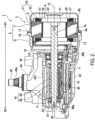
- FIG. 1 is a perspective view of a motor device 1 used in a vehicle.
- FIG. 2 is a cross-sectional view taken along the line II-II of FIG. 1 .
- the motor device 1 is used, for example, as a drive source for a wiper device of the vehicle.
- the motor device 1 includes a motor 2, a decelerator 3 that decelerates and outputs the rotation of the motor 2, and a controller 4 that performs the drive control of the motor 2.
- the term “axial direction” simply means the direction along the rotating axis line direction of a rotating shaft 31 of the motor 2.
- the term “circumferential direction” simply means the circumferential direction of the rotating shaft 31.
- radial direction simply means the radial direction of the rotating shaft 31.
- first direction one end side of the rotating shaft 31 (the side where the arrow points to D1 in FIG. 2 and FIG. 3 )
- second direction the other end side of the rotating shaft 31 (the side where the arrow points to D2 in FIG. 2 and FIG. 3 )
- the motor 2 includes a motor case 5, a substantially cylindrical stator 8 housed in the motor case 5, and a rotor 9 arranged on the radial inner side of the stator 8 and provided rotatably with respect to the stator 8.
- the motor 2 of the present embodiment is a so-called brushless motor that does not require a brush to supply electric power to the stator 8.
- the motor case 5 is made of a material having excellent heat dissipation such as an aluminum alloy.
- the motor case 5 is composed of a first motor case (frame) 6 configured to be divisible in the axial direction, and a second motor case 7.
- the first motor case 6 and the second motor case 7 are each formed in a bottomed cylindrical shape.
- the first motor case 6 is integrally molded with a gear case 40, so that a bottom portion 10 is connected to the gear case 40 of the decelerator 3.
- the first motor case 6 and the gear case 40 are formed into a predetermined shape by casting and molding a molten aluminum alloy or the like.
- a through hole through which the rotating shaft 31 of the motor 2 can be inserted is formed at substantially the center of the bottom portion 10 in the radial direction.
- the motor case 5 and the gear case 40 constitute a casing of the motor device 1.
- outer flange portions 16 and 17 extending toward the radial outer side are respectively formed at the openings 6a and 7a of the first motor case 6 and the second motor case 7.
- the motor case 5 has an internal space formed by abutting the outer flange portions 16 and 17 against each other.
- the stator 8 and the rotor 9 are arranged in the internal space of the motor case 5.
- the stator 8 is press-fitted and fixed to a step portion (first, second, and third core receiving portions 71, 72, and 73 (see FIG. 5 ) described later) formed on an inner circumferential wall 12 of the first motor case 6, and is arranged along the outer circumference of the rotor 9.
- a step portion first, second, and third core receiving portions 71, 72, and 73 (see FIG. 5 ) described later
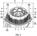
- FIG. 3 is a perspective view of the motor 2 from which the second motor case 7 is removed.
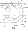
- FIG. 4 is a plan view of the stator 8 as viewed from the axial direction. As shown in FIG. 2 to FIG. 4 , the stator 8 includes a stator core 20 composed of laminated steel plates (electromagnetic steel plates) and a plurality of coils 27 wound around the stator core 20.
- the stator core 20 has an annular core body portion 21, a plurality of (for example, six in the present embodiment) teeth 22 projecting toward the radial inner side from the inner circumferential portion of the core body portion 21, a plurality of (for example, six in the present embodiment) manufacturing error absorbing portions 23 formed on the outer circumferential portion of the core body portion 21, and a plurality of (for example, two in the present embodiment) fastening portions (an example of the fixing portion in the claims) 24.
- the manufacturing error absorbing portion 23 absorbs manufacturing errors between the motor case 5 and the stator 8.
- the manufacturing error absorbing portion 23 is a tongue piece that is made flexible in the radial direction by cutting off a part of the outer circumferential portion of the core body portion 21.
- the manufacturing error absorbing portion 23 is arranged on an extension line of the teeth 22 in the radial direction. Further, the manufacturing error absorbing portion 23 is provided on the inner circumference (that is, the radial inner side) of the outermost diameter of the core body portion 21 (specifically, the outer circumferential edge 21a of the core body portion 21).
- the reason why the manufacturing error absorbing portion 23 is arranged on the extension line of the teeth 22 in the radial direction on the outer circumferential portion of the core body portion 21 is that the stator 8 has increased mechanical strength against an external force in the radial direction at the locations where the teeth 22 are provided and is unlikely to be deformed in the radial direction at the locations where the teeth 22 are provided.
- the manufacturing error absorbing portion 23 is arranged on the extension line of the teeth 22 in the radial direction, the magnetic path formed by the core body portion 21 is not obstructed. Details of this will be described later.
- the three manufacturing error absorbing portions 23 provided at intervals of 120° in the circumferential direction are supported by the first motor case 6 in the radial direction as well as in the axial direction.
- the three manufacturing error absorbing portions 23 supported by the first motor case 6 will be described as the first manufacturing error absorbing portion 23A, the second manufacturing error absorbing portion 23B, and the third manufacturing error absorbing portion 23C.
- Two fastening portions 24 are provided so as to face each other in the radial direction with the rotating axis line (axial center C1) of the rotating shaft 31 as the center.
- the two fastening portions 24 are provided on the outer circumference (that is, the radial outer side) with respect to the outermost diameter of the core body portion 21 (specifically, the outer circumferential edge 21a of the core body portion 21).
- One of the two fastening portions 24 is arranged side by side with the first manufacturing error absorbing portion 23A in the circumferential direction.
- the first fastening portion 24A the one fastening portion 24 arranged side by side with the first manufacturing error absorbing portion 23A in the circumferential direction
- the second fastening portion 24B the one fastening portion 24 provided between the second manufacturing error absorbing portion 23B and the third manufacturing error absorbing portion 23C in the circumferential direction.
- the first fastening portion 24A and the second fastening portion 24B are each formed with an attachment hole (an example of the fixing hole in the claims) 24a penetrating in the axial direction.
- a fastening screw (an example of the fixing member in the claims) 28 is inserted into each attachment hole 24a.
- the first fastening portion 24A and the second fastening portion 24B are arranged on the side of the rotating shaft 31 with respect to the line (tangent line C5) perpendicular to the rotating axis line (axial center C4) of an output shaft 48, among the tangent lines of the outer circumferential edge 21a of the core body portion 21.
- the first fastening portion 24A and the second fastening portion 24B are arranged on the side of the rotating shaft 31 with respect to the line (tangent line C6) parallel to the rotating axis line (axial center C4) of the output shaft 48, among the tangent lines of the outer circumferential edge 21a of the core body portion 21.
- the fastening portions 24A and 24B can be prevented from projecting from the outer surface of the motor device 1 in the directions perpendicular to and parallel to the rotating axis line (axial center C4) of the output shaft 48, so the motor device 1 can be miniaturized.
- the inner circumferential surface and each tooth 22 of the core body portion 21 are covered with an insulator 26 made of resin.
- the coil 27 is wound around the corresponding predetermined teeth 22 from above the insulator 26.
- Each coil 27 generates a magnetic field for rotating the rotor 9 by feeding power from the controller 4.
- the core body portion 21 forms an annular magnetic path. At this time, the magnetic path is formed in an arc shape as viewed from the axial direction across the adjacent teeth 22 in the circumferential direction. Therefore, in the outer circumferential portion of the core body portion 21, almost no magnetic flux is formed on the extension line of the teeth 22 in the radial direction. Therefore, the manufacturing error absorbing portion 23 does not obstruct the magnetic path.
- the rotor 9 is rotatably arranged on the radial inner side of the stator 8 via a minute gap, and rotates by receiving the magnetic field of the stator 8.
- the rotor 9 includes the rotating shaft 31, a substantially cylindrical rotor core 32 having a shaft core hole 69 to which the rotating shaft 31 is press-fitted and fixed on the inner circumferential portion, and four permanent magnets 33 assembled to the outer circumferential portion of the rotor core 32 (see FIG. 3 , FIG. 5 , FIG. 6 , etc.).
- the rotating shaft 31 is integrally formed with a worm shaft 44 that constitutes the decelerator 3.
- the worm shaft 44 is not limited thereto, and may be formed separately from the rotating shaft 31 and connected to the end portion of the rotating shaft 31.
- the rotating shaft 31 and the worm shaft 44 are rotatably supported by a gear case 40 (casing) via bearings 46 and 47.
- the rotating shaft 31 and the worm shaft 44 rotate around the rotating axis line (axial center C1).
- a ferrite magnet for example, is used as the permanent magnet 33.
- the permanent magnet 33 is not limited thereto, and a neodymium bond magnet, a neodymium sintered magnet, or the like can also be used.
- the decelerator 3 includes the gear case 40 integrated with the motor case 5, and a deceleration mechanism 41 housed in the gear case 40.
- the gear case 40 is made of a metal material having excellent heat dissipation such as an aluminum alloy.
- the gear case 40 is formed in a box shape having an opening 40a on one surface.
- the gear case 40 has a gear housing portion 42 that houses the deceleration mechanism 41 inside. Further, on a side wall 40b of the gear case 40, an opening 43 that communicates the gear housing portion 42 with the through hole of the first motor case 6 is formed at a location where the first motor case 6 is integrally formed.
- a bearing boss 49 having a substantially cylindrical shape is provided to project on a bottom wall 40c of the gear case 40.
- the bearing boss 49 is for rotatably supporting the output shaft 48 of the deceleration mechanism 41, and a slide bearing (not shown) is arranged on the inner circumferential side.
- An O-ring (not shown) is mounted on the inner side of the tip portion of the bearing boss 49.
- a plurality of ribs 52 for ensuring rigidity are provided to project on the outer circumferential surface of the bearing boss 49.
- the deceleration mechanism 41 housed in the gear housing portion 42 is composed of the worm shaft 44 and a worm wheel 45 meshed with the worm shaft 44. Two end portions of the worm shaft 44 in the axial direction are rotatably supported by the gear case 40 via the bearings 46 and 47.
- the worm shaft 44 is provided coaxially and integrally with the rotating shaft 31 of the motor 2.
- the output shaft 48 of the deceleration mechanism 41 is coaxially and integrally provided on the worm wheel 45.
- the worm wheel 45 and the output shaft 48 are arranged so that the rotating axis lines thereof are substantially orthogonal to the rotating axis line (axial center C1) of the worm shaft 44 (the rotating shaft 31 of the motor 2).
- the output shaft 48 projects to the outside via the bearing boss 49 of the gear case 40.
- a spline 48a that can be connected to a motor-driven target article is formed at the projecting tip of the output shaft 48.
- the worm wheel 45 is provided with a sensor magnet (not shown). The position of this sensor magnet is detected by a magnetic detection element 61 provided in the controller 4, which will be described later. In other words, the rotational position of the worm wheel 45 is detected by the magnetic detection element 61 of the controller 4.
- the controller 4 has a controller board 62 on which the magnetic detection element 61 is mounted.
- the controller board 62 is arranged in the opening 40a of the gear case 40, so that the magnetic detection element 61 faces the sensor magnet (not shown) of the worm wheel 45.
- the opening 40a of the gear case 40 is closed by a cover 63.
- Terminal portions of a plurality of coils 27 drawn from the stator core 20 are connected to the controller board 62. Further, the terminal of a connector 11 (see FIG. 1 ) provided on the cover 63 is electrically connected to the controller board 62.
- a power module (not shown) composed of switching elements such as FETs (Field Effect Transistors) that control the drive voltage supplied to the coils 27, and a capacitor (not shown) that smoothens the voltage are mounted on the controller board 62.
- FIG. 5 is a plan view of the first motor case 6 as viewed from the axial direction of the rotating shaft 31.
- FIG. 6 is a perspective view showing the first fastening receiving portion 81 and the first core receiving portion 71 of the first motor case 6.
- a housing space opened by the opening 6a is formed by the bottom portion 10 and the inner circumferential wall 12.
- the inner circumferential wall 12 is formed in a circular shape centered on the axial center C1.
- the first motor case 6 includes a plurality of core receiving portions 71, 72, and 73 formed by forming a step portion near the bottom portion 10 of the inner circumferential wall 12, a plurality of core receiving portions 74, 75, and 76 provided at locations corresponding to the core receiving portions 71, 72, and 73 of the inner circumferential wall 12, a plurality of mounting seat portions 77 and 78 on which the fastening portions 24 of the stator 8 are placed, and a plurality of fastening receiving portions (an example of the fixing receiving portion in the claims) 81 and 82.
- the present embodiment illustrates three core receiving portions, i.e. the first core receiving portion 71, the second core receiving portion 72, and the third core receiving portion 73, as the core receiving portions (an example of the core receiving portion in the claims) 71, 72, and 73 formed by forming the step portion near the bottom portion 10 of the inner circumferential wall 12, but the number thereof may be arbitrarily selected. Furthermore, the present embodiment illustrates three core receiving portions, i.e. the fourth core receiving portion 74, the fifth core receiving portion 75, and the sixth core receiving portion 76, as the plurality of core receiving portions 74, 75, and 76 of the inner circumferential wall 12, but the number thereof may be arbitrarily selected. In addition, the present embodiment illustrates two mounting seat portions, i.e.
- the present embodiment illustrates two fastening receiving portions, i.e. the first fastening receiving portion 81 and the second fastening receiving portion 82, as the plurality of fastening receiving portions 81 and 82, but the number thereof may be arbitrarily selected.
- the present embodiment since one end of the stator core 20 in the axial direction is supported at three points of the core receiving portions 71, 72, and 73 in a well-balanced manner, there may be at least two fastening receiving portions 81 and 82. In this case, the number of fastening screws 28 can be reduced to two, and the number of parts can be reduced.
- the core receiving portions 71, 72, and 73 are preferably formed by cutting because high dimensional accuracy in the axial direction is required. If the core receiving portions 71, 72, and 73 are provided on the mounting seat portions 77 and 78, the core receiving portions 71 and 72 cannot be cut at the same time with one tool. Therefore, in the present embodiment, the core receiving portions 71, 72, and 73 are provided on the radial inner side with respect to the mounting seat portions 77 and 78. As a result, the core receiving portions 71 and 72 can be cut at the same time with one tool, so that the core receiving portions 71, 72, and 73 can be formed with high accuracy.
- the stator core 20 can be miniaturized. Specifically, as shown in FIG. 4 , the dimensions of the stator core 20 can be reduced in the direction perpendicular to the rotating axis line (axial center C4) of the output shaft 48 (direction along the tangent line C5) and in the direction parallel thereto (direction along the tangent line C6).
- a power feeding opening 84 is formed in the bottom portion 10 of the first motor case 6.
- a power feeding portion (not shown) for feeding power to the stator 8 is arranged in the power feeding opening 84.
- the first core receiving portion 71, the second core receiving portion 72, and the third core receiving portion 73 are provided on the inner circumferential wall 12 to avoid the power feeding opening 84, and are provided at three locations at intervals of 120° in the circumferential direction. That is, the first core receiving portion 71 to the third core receiving portion 73 are arranged so as to avoid the power feeding portion (not shown).
- the first core receiving portion 71, the second core receiving portion 72, and the third core receiving portion 73 project from the inner circumferential wall 12 toward the radial inner side, and each support surface facing the opening 6a is accurately formed (processed) so as to be orthogonal to the axis line C.
- the end portions in the axial direction of the first manufacturing error absorbing portion 23A, the second manufacturing error absorbing portion 23B, and the third manufacturing error absorbing portion 23C (see FIG. 4 ) of the stator 8 are abutted (supported) in the axial direction from the side of the opening 6a on the support surfaces of the first core receiving portion 71, the second core receiving portion 72, and the third core receiving portion 73.
- the fourth core receiving portion 74, the fifth core receiving portion 75, and the sixth core receiving portion 76 has a shape that projects from the support surfaces of the first core receiving portion 71, the second core receiving portion 72, and the third core receiving portion 73 toward the opening 6a.
- the end portions in the radial direction of the first manufacturing error absorbing portion 23A, the second manufacturing error absorbing portion 23B, and the third manufacturing error absorbing portion 23C of the stator 8 are abutted (supported) in the radial direction on the support surfaces, facing the radial inner side, of such fourth core receiving portion 74, fifth core receiving portion 75, and sixth core receiving portion 76.
- the first core receiving portion 71 and the fourth core receiving portion 74, the second core receiving portion 72 and the fifth core receiving portion 75, and the third core receiving portion 73 and the sixth core receiving portion 76 are respectively provided at the same positions in the circumferential direction. Further, the first core receiving portion 71 and the second core receiving portion 72 are arranged adjacent to both sides of the power feeding opening 84 in the circumferential direction, and the third core receiving portion 73 is arranged on the side opposite to the power feeding opening 84 with respect to the rotating shaft 31 (axial center C1).
- the core receiving portions 71, 72, and 73 and the core receiving portions 74, 75, and 76 are respectively arranged at intervals of 120° in the circumferential direction, so that the stator core 20 can be supported in a well-balanced manner.
- the first mounting seat portion 77 and the second mounting seat portion 78 project toward the radial outer side from the inner circumferential wall 12 so as to correspond to the fastening portions 24 of the stator 8. Further, the first mounting seat portion 77 and the second mounting seat portion 78 are arranged on the radial outer side with respect to the first core receiving portion 71, the second core receiving portion 72, and the third core receiving portion 73. That is, the first mounting seat portion 77 and the second mounting seat portion 78 are provided at intervals of 180° in the circumferential direction so as to face each other in the radial direction with the rotating axis line (axial center C1) of the first motor case 6 as the center.
- the first mounting seat portion 77 and the second mounting seat portion 78 are each provided with a screw hole (an example of the fixed hole in the claims) 86 extending in the axial direction.
- a screw portion 28a (see FIG. 3 ) of the fastening screw 28 for fixing the stator 8 to the first motor case 6 is screwed into the screw hole 86.
- the first mounting seat portion 77 is provided side by side with the first core receiving portion 71 in the circumferential direction so as to correspond to the first fastening portion 24A of the stator 8. That is, the first mounting seat portion 77 is provided in the vicinity of the first core receiving portion 71 and the fourth core receiving portion 74 in the circumferential direction and the radial direction.
- the second mounting seat portion 78 is provided between the second core receiving portion 72 and the fifth core receiving portion 75 and the third core receiving portion 73 and the sixth core receiving portion 76 in the circumferential direction so as to correspond to the second fastening portion 24B of the stator 8.
- the first fastening receiving portion 81 and the second fastening receiving portion 82 are respectively provided on the first mounting seat portion 77 and the second mounting seat portion 78. That is, the first fastening receiving portion 81 and the second fastening receiving portion 82 are provided at intervals of 180° in the circumferential direction so as to face each other with the axial center C1 of the stator 8 as the center. Further, the first fastening receiving portion 81 and the second fastening receiving portion 82 are provided on the outer circumference (that is, radial outer side) of the arc C3 that passes through the center C2 of the screw hole 86 with the axial center C1 of the stator 8 as the center.
- FIG. 7 is a conceptual diagram in which the stator 8 is fastened and fixed to the first motor case 6 with the fastening screw 28.
- FIG. 8 is an enlarged conceptual diagram of the part VIII of FIG. 7 .
- the first fastening receiving portion 81 and the second fastening receiving portion 82 are formed in a substantially arc shape as viewed from the axial direction. That is, the outer circumferences of the first fastening receiving portion 81 and the second fastening receiving portion 82 are formed in a substantially arc shape along the outer circumferences of the first mounting seat portion 77 and the second mounting seat portion 78, respectively. Further, the inner circumferences of the first fastening receiving portion 81 and the second fastening receiving portion 82 are formed in an arc shape along the screw hole 86, respectively.
- first fastening receiving portion 81 and the second fastening receiving portion 82 in the longitudinal direction as viewed from the axial direction are formed in a straight line shape along the arc C3.
- the first fastening receiving portion 81 and the second fastening receiving portion 82 have a quadrangular (rectangular) cross-sectional shape along the axial direction. Accordingly, the receiving surfaces (upper end surfaces) 81a and 82a of the first fastening receiving portion 81 and the second fastening receiving portion 82 are formed flat. As a result, the receiving surfaces 81a and 82a of the first fastening receiving portion 81 and the second fastening receiving portion 82 are ensured to be relatively large. Furthermore, as shown in FIG. 7 and FIG. 8 , the first fastening receiving portion 81 and the second fastening receiving portion 82 are provided at positions overlapping the head portions 28b of the fastening screws 28 in the axial direction.
- the height of each support surface of the first core receiving portion 71, the second core receiving portion 72, and the third core receiving portion 73 in the axial direction from the bottom portion 10 are greater than the heights of the first mounting seat portion 77 and the second mounting seat portion 78 in the axial direction from the bottom portion 10.
- the support surfaces of the first core receiving portion 71, the second core receiving portion 72, and the third core receiving portion 73, and the receiving surfaces 81a and 82a of the first fastening receiving portion 81 and the second fastening receiving portion 82 project in the direction (that is, the direction of the opening 6a) of the stator 8 (the core body portion 21, see FIG. 7 ) with respect to the first mounting seat portion 77 and the second mounting seat portion 78 in the axial direction.
- the positions of the receiving surfaces 81a and 82a of the first fastening receiving portion 81 and the second fastening receiving portion 82 are, for example, -0.1 mm to 0.3 mm with respect to the support surfaces of the core receiving portions 71, 72, and 73.
- the receiving surfaces 81a and 82a of the first fastening receiving portion 81 and the second fastening receiving portion 82 with respect to the support surfaces of the core receiving portions 71, 72, and 73 are not limited thereto.
- the core body portion 21 of the stator 8 and the support surfaces of the core receiving portions 71, 72, and 73 can be brought into contact with each other by the fastening torque of the fastening screw 28.
- stator 8 when the stator 8 is assembled, the stator 8 is first arranged in the housing space from the opening 6a of the first motor case 6.
- the stator 8 is provided with the first manufacturing error absorbing portion 23A, the second manufacturing error absorbing portion 23B (see FIG. 4 ), and the third manufacturing error absorbing portion 23C.
- the first core receiving portion 71, the second core receiving portion 72, and the third core receiving portion 73 receive the first manufacturing error absorbing portion 23A, the second manufacturing error absorbing portion 23B, and the third manufacturing error absorbing portion 23C in the axial direction.
- the first manufacturing error absorbing portion 23A, the second manufacturing error absorbing portion 23B, and the third manufacturing error absorbing portion 23C are supported by the first core receiving portion 71, the second core receiving portion 72, and the third core receiving portion 73 in the axial direction.
- first manufacturing error absorbing portion 23A, the second manufacturing error absorbing portion 23B, and the third manufacturing error absorbing portion 23C are supported by the fourth core receiving portion 74, the fifth core receiving portion 75, and the sixth core receiving portion 76 in a form of stretching in the radial direction.
- the receiving surfaces 81a and 82a of the first fastening receiving portion 81 and the second fastening receiving portion 82 receive the first fastening portion 24A and the second fastening portion 24B of the stator 8 in the axial direction.
- first fastening portion 24A and the second fastening portion 24B of the stator 8 are supported in the axial direction by the receiving surfaces 81a and 82a of the first fastening receiving portion 81 and the second fastening receiving portion 82.
- the fastening screws 28 are inserted into the screw holes 86 of the first mounting seat portion 77 and the second mounting seat portion 78 from above the first mounting seat portion 77 and the second mounting seat portion 78. Then, the screw portion 28a of the fastening screw 28 is fastened into the screw hole 86 of each of the mounting seat portions 77 and 78. At this time, the first fastening portion 24A and the second fastening portion 24B fastened and fixed by the fastening screws 28 are received by the receiving surfaces 81a and 82a of the first fastening receiving portion 81 and the second fastening receiving portion 82.
- the stator 8 is supported in the axial direction by the first core receiving portion 71, the second core receiving portion 72, and the third core receiving portion 73, and is fastened and fixed to the first motor case 6 in a state of being supported in the radial direction by the fourth core receiving portion 74, the fifth core receiving portion 75, and the sixth core receiving portion 76.
- the rotor 9 is rotatably arranged on the radial inner side of the stator 8 via a minute gap.
- the rotor 9 rotates by receiving the rotating magnetic field formed by the stator 8.
- an end portion (one end portion) of the rotating shaft 31 on the side opposite to the side of the worm shaft 44 is press-fitted (fitted) into the shaft core hole 69 of the rotor core 32.
- the rotor core 32 rotates, so that the rotating shaft 31 rotates integrally with the rotor core 32.
- the rotating shaft 31 rotates, so that the output shaft 48 rotates via the worm shaft 44 and the worm wheel 45.
- the end portions in the axial direction of the first fastening portion 24A and the second fastening portion 24B of the stator 8 fastened and fixed by the fastening screws 28 are received by the receiving surfaces 81a and 82a of the first fastening receiving portion 81 and the second fastening receiving portion 82 of the first motor case 6.
- the end portions in the axial direction of the core body portion 21 (the first manufacturing error absorbing portion 23A, the second manufacturing error absorbing portion 23B, and the third manufacturing error absorbing portion 23C) of the stator 8 are received by the first core receiving portion 71, the second core receiving portion 72, and the third core receiving portion 73.
- the fastening force F1 of the fastening screw 28 can be received by the first fastening receiving portion 81 and the second fastening receiving portion 82 through the first fastening portion 24A and the second fastening portion 24B.
- the fastening force F1 of the fastening screw 28 can suppress the radial center portion of the stator 8 from rising in the axial direction with the first core receiving portion 71, the second core receiving portion 72, and the third core receiving portion 73 as fulcrums, and the deformation of the stator 8 can be kept small.
- the tilt of the stator 8 can be suppressed, and further the tilt direction of the stator 8 can be controlled.
- the roundness of the inner diameter of the stator 8 can be satisfactorily secured, and the assembly accuracy of the motor 2 (see FIG. 2 ) can be improved. Therefore, the operating noise of the motor 2 can be reduced, further the air gap between the stator 8 and the rotor 9 can be easily secured, and the interference between the stator 8 and the rotor 9 can be prevented.
- first fastening receiving portion 81 and the second fastening receiving portion 82 are provided on the outer circumference (that is, the radial outer side) of the arc C3 passing through the center C2 of the screw hole 86 with the axial center C1 of the stator 8 as the center. Therefore, a part of the fastening force F1 of the fastening screw 28 can be received on the opposite side of the first core receiving portion 71, the second core receiving portion 72, and the third core receiving portion 73 (particularly, the first core receiving portion 71) in the radial direction with respect to the fastening screw 28.
- first fastening receiving portion 81 and the second fastening receiving portion 82 are provided at positions overlapping the head portions 28b of the fastening screws 28 in the axial direction. Therefore, the fastening force F1 of the fastening screws 28 can be efficiently received by the first fastening receiving portion 81 and the second fastening receiving portion 82. As a result, it is possible to suitably suppress the deformation that the radial center portion of the stator 8 is raised in the axial direction with the first core receiving portion 71, the second core receiving portion 72, and the third core receiving portion 73 as fulcrums due to the fastening force F1 of the fastening screw 28.
- first fastening receiving portion 81 and the second fastening receiving portion 82 are provided so as to face each other with the axial center C1 of the first motor case 6 as the center. As a result, the fastening force F1 of the fastening screw 28 can be received in a well-balanced manner by the first fastening receiving portion 81 and the second fastening receiving portion 82 on both sides of the stator 8.
- the first core receiving portion 71 is arranged side by side in the circumferential direction on one first fastening receiving portion 81.
- the fastening force F1 of the fastening screw 28 received by the first fastening receiving portion 81 can be received by the first fastening receiving portion 81 and the first core receiving portion 71 closest to the first fastening receiving portion 81.
- the fastening force F1 of the fastening screw 28 can be received by the first fastening receiving portion 81 and the first core receiving portion 71 located on both sides of the fastening screw 28 (the attachment hole 24a, the screw hole 86).
- the support surfaces of the first core receiving portion 71, the second core receiving portion 72, and the third core receiving portion 73, and the receiving surfaces 81a and 82a of the first fastening receiving portion 81 and the second fastening receiving portion 82 project in the direction of the stator 8 (the core body portion 21) with respect to the first mounting seat portion 77 and the second mounting seat portion 78 in the axial direction. Therefore, when the core body portion 21 is fastened to the first motor case 6 by the fastening screw 28, the portion of the core body portion 21 that comes into contact with the first motor case 6 (the portion received by the first motor case 6) can be reliably arranged in a well-balanced manner in the circumferential direction. Therefore, the load applied to the core body portion 21 by the fastening force F1 of the fastening screw 28 can be distributed in a well-balanced manner.
- first core receiving portion 71, the second core receiving portion 72, and the third core receiving portion 73 are arranged at three locations at intervals of 120° in the circumferential direction.
- first manufacturing error absorbing portion 23A, the second manufacturing error absorbing portion 23B, and the third manufacturing error absorbing portion 23C of the stator 8 can be supported in a more balanced manner in the axial direction by three core receiving portions, i.e. the first core receiving portion 71, the second core receiving portion 72, and the third core receiving portion 73.
- the positions of the receiving surfaces 81a and 82a of the first fastening receiving portion 81 and the second fastening receiving portion 82 are, for example, -0.1 mm to 0.3 mm with respect to the support surfaces of the core receiving portions 71, 72, and 73. Therefore, the fastening force F1 of the fastening screw 28 can be suitably received by the first fastening receiving portion 81 and the second fastening receiving portion 82 closest to the location where the fastening force F1 is generated.
- the first core receiving portion 71, the second core receiving portion 72, and the third core receiving portion 73 are arranged to avoid the power feeding opening 84 (the power feeding portion). Therefore, the power feeding portion can be laid out (arranged) at the optimum position without being affected by the first core receiving portion 71, the second core receiving portion 72, and the third core receiving portion 73.
- FIG. 9 is a plan view of a first motor case 100 of the comparative example as viewed from the axial direction.
- FIG. 10 is a conceptual diagram in which the stator 8 is fastened and fixed to the first motor case 100 of the comparative example with the fastening screw 28.
- FIG. 11 is a simulation diagram exaggeratedly showing the tilt (deformation) of the stator 8 fastened and fixed to the first motor case 100 of the comparative example with the fastening screw 28.
- the first motor case 100 of the comparative example does not include the first fastening receiving portion 81 and the second fastening receiving portion 82 of the embodiment. Therefore, it can be confirmed that, in the stator 8, the portion 21b, corresponding to the tooth 22A of the teeth 22, of the annular core body portion 21 tilts relatively largely to the radial inner side as shown by the arrow A. It can also be confirmed that the portion 21c, corresponding to the tooth 22B of the teeth 22, tilts relatively largely to the radial outer side as shown by the arrow B.
- FIG. 12 is a simulation diagram exaggeratedly showing the tilt (deformation) of the stator 8 fastened and fixed to the first motor case 6 of the embodiment with the fastening screw 28.
- the first motor case 6 of the embodiment includes the first fastening receiving portion 81 and the second fastening receiving portion 82 of the embodiment.
- the tilt of the portion, corresponding to the plurality of (six in the embodiment) teeth 22, of the core body portion 21 of the stator 8 is suppressed. That is, it can be confirmed that the tilt of the entire core body portion 21 can be suppressed.
- the core body portion 21 is controlled in a well-balanced manner, so that the tilt direction of the portion corresponding to the plurality of (six in the embodiment) teeth 22 does not vary. That is, the tilt direction of the entire core body portion 21 can be controlled in a well-balanced manner.
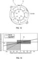
- FIG. 13 is a graph illustrating the tilt (mm) and the inner diameter displacement (mm) of the stator 8 after fastening with respect to the stator 8 before fastening when the stator 8 is fastened to the first motor case 6 with the fastening screw 28.
- the hatched portion G1 indicates the range corresponding to the projection amount of the receiving surfaces 81a and 82a in the embodiment, and the hatched portion G2 indicates the range corresponding to the projection amount of the receiving surfaces 81a and 82a in the comparative example.
- the vertical axis of the graph shown by the solid line indicates the tilt (mm) of the stator 8.
- the tilt of the stator 8 refers to the displacement amount in the radial direction when the radial centers of the core body portion 21 measured at measurement points provided at a plurality of locations along the axial direction of the stator 8 are compared before and after the fastening screw 28 is fastened.
- the vertical axis shows the tilt toward the side of the gear case 40 in the axial direction of the output shaft 48 (axial center C4) as + and shows the tilt toward the side of the cover 63 in the axial direction of the output shaft 48 (axial center C4) as - with the radial center of the core body portion 21 before fastening as the origin.
- the horizontal axis indicates the projection amounts of the receiving surfaces 81a and 82a of the first fastening receiving portion 81 and the second fastening receiving portion 82 with respect to the support surfaces of the core receiving portions 71, 72, and 73.
- the vertical axis of the graph shown by the dotted line indicates the inner diameter displacement (mm) of the stator 8.
- the inner diameter displacement of the stator 8 refers to the displacement amount in the radial direction when the measurement points provided on the teeth 22 are compared before and after the fastening screw 28 is fastened.
- the vertical axis shows the displacement direction of the measurement point having the largest displacement among the measurement points as - and the opposite direction as +.
- the horizontal axis indicates the projection amounts of the receiving surfaces 81a and 82a of the first fastening receiving portion 81 and the second fastening receiving portion 82 with respect to the support surfaces of the core receiving portions 71, 72, and 73.
- FIG. 13 only, the data of the tooth 22A having the largest displacement amount among the teeth 22 is shown.
- the projection amount of each of the receiving surfaces 81a and 82a is set to -0.4 mm to 0 mm.
- the tilt direction of the portion, corresponding to the tooth 22A, of the core body portion 21 is biased toward the radial inner side as shown by the arrow A, and the displacement amount is large.
- the projection amount of each of the receiving surfaces 81a and 82a is set to -0.1 mm to 0.3 mm.
- the tilt direction of the portion, corresponding to the tooth 22A, of the core body portion 21 is controlled in a well-balanced manner toward the radial inner and outer sides, and the tilt and the displacement amount of the inner diameter displacement of the stator 8 are kept small.
- the roundness of the inner diameter of the stator 8 can be satisfactorily secured, and the assembly accuracy of the motor 2 (see FIG. 2 ) can be improved.
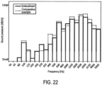
- FIG. 22 shows the sound pressure (dB(A)) at each frequency (Hz) of the operating noise of the motor device 1 in the embodiment of the present invention and the comparative example. Further, the graph shown by the solid line is the data of the embodiment, and the graph shown by the dotted line shows the data of the comparative example. In FIG. 22 , it can be confirmed that the sound pressure of the motor device 1 of the embodiment is reduced particularly in the frequency band of 400 Hz as compared with the comparative example.
- FIG. 23A and FIG. 23B show the magnitude (dB) of vibration at each frequency (Hz) of the vibration of the motor device 1 in the embodiment of the present invention and the comparative example. Further, the graph shown by the solid line is the data of the embodiment, and the graph shown by the dotted line shows the data of the comparative example.
- FIG. 23A shows data on radial vibration of the embodiment and the comparative example.
- FIG. 23B shows data on axial vibration of the embodiment and the comparative example. In FIG. 23A and FIG. 23B , it can be confirmed that the motor device 1 of the embodiment has reduced vibration particularly in the frequency band of 200 Hz as compared with the comparative example.
- the motor device when the motor device is arranged in a vehicle, there is a concern that the noise caused by the operating noise and vibration of the motor device may propagate into the vehicle interior.
- the noise caused by the operating noise and vibration of the motor device may propagate into the vehicle interior.
- low-frequency sounds are more likely to propagate into the vehicle interior than high-frequency sounds. Therefore, when the embodiment of the present invention is mounted on a vehicle, the operating noise and vibration of the motor device 1 can be suppressed in the low frequency band so the propagation of noise into the vehicle interior can be effectively suppressed.
- first modified example to the eighth modified example of the first fastening receiving portion 81 will be described with reference to FIG. 14 to FIG. 21 .
- first modified example to the eighth modified example the same and similar configurations as those in the embodiment are designated by the same reference numerals, and detailed description thereof will be omitted.
- FIG. 14 is a perspective view showing the first fastening receiving portion 110 of the first modified example.
- the outer circumference of the first fastening receiving portion 110 of the first modified example is formed in an arc shape along the outer circumference of the first mounting seat portion 77, and the inner circumference is formed in an arc shape along the screw hole 86.
- both end portions of the first fastening receiving portion 110 in the longitudinal direction as viewed from the axial direction are formed along straight lines that extend radially at predetermined angles from the center C2 of the screw hole 86 toward the radial outer side.
- the first fastening receiving portion 110 has a sectional shape in the radial direction that is formed in a quadrangular shape (rectangular shape), and the receiving surface 110a is formed flat.
- FIG. 15 is a perspective view showing the first fastening receiving portion 111 of the second modified example.
- the outer circumference of the first fastening receiving portion 111 of the second modified example is formed in a curved shape along the outer circumference of the first mounting seat portion 77.
- the inner circumference of the first fastening receiving portion 110 is formed in a polygonal shape along the outer circumference.
- one end portion of the first fastening receiving portion 110 in the longitudinal direction as viewed from the axial direction is formed along a straight line that extends radially at a predetermined angle from the center C2 of the screw hole 86 toward the radial outer side.
- the other end portion of the first fastening receiving portion 110 in the longitudinal direction as viewed from the axial direction is formed at a location where the inner circumference and the outer circumference intersect.
- the first fastening receiving portion 111 has a sectional shape in the radial direction that is formed in a quadrangular shape (rectangular shape), and the receiving surface 111a is formed flat.
- FIG. 16 is a conceptual diagram showing the first fastening receiving portion 112 of the third modified example.
- the first fastening receiving portion 112 of the third modified example has a sectional shape in the radial direction that is formed in an arc shape.
- FIG. 17 is a conceptual diagram showing the first fastening receiving portion 113 of the fourth modified example.
- the first fastening receiving portion 113 of the fourth modified example has a sectional shape in the radial direction that is formed in a triangular shape.
- FIG. 18 is a conceptual diagram showing the first fastening receiving portion 114 of the fifth modified example. As shown in FIG. 18 , the first fastening receiving portion 114 of the fifth modified example has a sectional shape in the radial direction that is formed in a trapezoidal shape.
- FIG. 19 is a conceptual diagram showing the first fastening receiving portion 115 of the sixth modified example.
- the first fastening receiving portion 115 of the sixth modified example has a sectional shape in the radial direction that is formed in an arched semi-cylindrical shape.
- FIG. 20 is a conceptual diagram showing the first fastening receiving portion 116 of the seventh modified example.
- the first fastening receiving portion 116 of the seventh modified example has a sectional shape in the radial direction that is formed in a pentagonal home base shape.
- FIG. 21 is a conceptual diagram showing the first fastening receiving portion 117 of the eighth modified example.
- the first fastening receiving portion 117 of the eighth modified example has a sectional shape in the radial direction that is formed in a convex shape.
- the tip of the first fastening receiving portion 117 may be formed in a convex curve.
- the configurations of the modified examples can also achieve the same effects as the above-described embodiment.
- the present invention is not limited to the above-described embodiment, and includes various modifications to the above-described embodiment without departing from the spirit of the present invention.
- the above-described embodiment illustrates the fastening screw 28 as an example of the fixing member, but the present invention is not limited thereto. Any member that can fix the core body portion 21 of the stator 8 to the first motor case 6 may be used.
- a rivet or the like may be used instead of the fastening screw 28.
- the above-described embodiment illustrates a case where the motor device 1 is used as the drive source for a vehicle wiper device.
- the present invention is not limited thereto, and the above-described motor device 1 can be applied to various electric devices.
- third manufacturing error absorbing portion 24 ... fastening portion (fixing portion); 24a ... attachment hole (fixing hole); 24A ... first fastening portion (fixing portion); 24B ... second fastening portion (fixing portion); 26 ... insulator; 27 ... coil; 28 ... fastening screw (fixing member); 28a ... screw portion; 28b ... head portion; 31 ... rotating shaft; 32 ... rotor core; 33 ... permanent magnet; 40 ... gear case; 40a ... opening; 40b ... side wall; 40c ... bottom wall; 41 ... deceleration mechanism; 42 ... gear housing portion; 43 ... opening; 44 ... worm shaft; 45 ... worm wheel; 46, 47 ... bearing; 48 ...
Landscapes
- Engineering & Computer Science (AREA)
- Power Engineering (AREA)
- Iron Core Of Rotating Electric Machines (AREA)
- Motor Or Generator Frames (AREA)
Abstract
Description
- The present invention relates to a motor.
- As the motor used for a vehicle wiper device or the like, there is a motor in which a rotor is arranged on the radial inner side of a stator wound with coils, and the stator and the rotor are accommodated in a frame (see, for example, Patent Literature 1). In some motors of this type, the stator accommodated in the frame is supported by core receiving portions of the frame in a state of being fastened by a pair of fastening screws. The stator has an annular core body portion, and a pair of fastening screws are arranged on the outer circumference (that is, the radial outer side) of the core body portion.
- [Patent Literature 1]
Japanese Patent Laid-Open No. 2019-187132 - However, when the fastening screw is arranged on the outer circumference of the core body portion and fastened, there is a possibility that the radial center portion of the stator may be deformed to rise in the axial direction with the core receiving portion as a fulcrum. Since the radial center portion of the stator rises, for example, the stator tilts in a direction intersecting between two points of the two fastening screws, and it is difficult to ensure the roundness of the inner diameter of the stator. For this reason, the operating noise of the motor deteriorates, and further the rotor and the stator may interfere with each other.
- Therefore, the present invention provides a motor capable of suppressing the tilt of the stator and further controlling the tilt direction of the stator by preventing the stator from rising. Solution to Problem
- In order to solve the above problem, a motor according to the present invention includes: a stator around which coils are wound and which forms a rotating magnetic field for rotating a rotor; and a frame which houses the stator. The stator includes: a core body portion which forms an annular magnetic path; and a fixing portion which projects toward a radial outer side from an outer circumferential surface of the core body portion. The fixing portion has a fixing hole which is formed to penetrate along a rotating axis line direction of the rotor and through which a fixing member for fixing the stator to the frame is inserted. The frame includes: a core receiving portion which receives an end portion of the core body portion in the rotating axis line direction; and a fixing receiving portion which receives an end portion of the fixing portion in the rotating axis line direction.
- According to the present invention, by preventing the stator from rising, the tilt of the stator can be suppressed and further the tilt direction of the stator can be controlled.
-
-
FIG. 1 is a perspective view of the motor device according to an embodiment of the present invention. -
FIG. 2 is a cross-sectional view taken along the line II-II ofFIG. 1 . -
FIG. 3 is a perspective view of the motor according to an embodiment of the present invention from which the second motor case is removed. -
FIG. 4 is a plan view of the stator according to an embodiment of the present invention as viewed from the axial direction. -
FIG. 5 is a plan view of the first motor case according to an embodiment of the present invention as viewed from the axial direction of the rotating shaft. -
FIG. 6 is a perspective view showing the first fastening receiving portion and the first core receiving portion of the first motor case according to an embodiment of the present invention. -
FIG. 7 is a conceptual diagram in which the stator is fastened and fixed to the first motor case according to an embodiment of the present invention with the fastening screw. -
FIG. 8 is an enlarged conceptual diagram of the part VIII ofFIG. 7 . -
FIG. 9 is a plan view of the first motor case of the comparative example as viewed from the axial direction. -
FIG. 10 is a conceptual diagram in which the stator is fastened and fixed to the first motor case of the comparative example with the fastening screw. -
FIG. 11 is a simulation diagram exaggeratedly showing the tilt of the stator fastened and fixed to the first motor case of the comparative example with the fastening screw. -
FIG. 12 is a simulation diagram exaggeratedly showing the tilt of the stator fastened to the first motor case according to an embodiment of the present invention with the fastening screw. -
FIG. 13 is a graph illustrating the tilt and inner diameter displacement of the stator according to an embodiment of the present invention and the comparative example. -
FIG. 14 is a perspective view showing the first fastening receiving portion of the first modified example according to an embodiment of the present invention. -
FIG. 15 is a perspective view showing the first fastening receiving portion of the second modified example according to an embodiment of the present invention. -
FIG. 16 is a conceptual diagram showing the first fastening receiving portion of the third modified example according to an embodiment of the present invention. -
FIG. 17 is a conceptual diagram showing the first fastening receiving portion of the fourth modified example according to an embodiment of the present invention. -
FIG. 18 is a conceptual diagram showing the first fastening receiving portion of the fifth modified example according to an embodiment of the present invention. -
FIG. 19 is a conceptual diagram showing the first fastening receiving portion of the sixth modified example according to an embodiment of the present invention. -
FIG. 20 is a conceptual diagram showing the first fastening receiving portion of the seventh modified example according to an embodiment of the present invention. -
FIG. 21 is a conceptual diagram showing the first fastening receiving portion of the eighth modified example according to an embodiment of the present invention. -
FIG. 22 is a graph illustrating the loudness of the operating noise of the motor device according to an embodiment of the present invention and the comparative example. -
FIG. 23A is a graph illustrating the magnitude of the vibration of the motor device according to an embodiment of the present invention and the comparative example. -
FIG. 23B is a graph illustrating the magnitude of the vibration of the motor device according to an embodiment of the present invention and the comparative example. - Next, embodiments of the present invention will be described with reference to the drawings.
-
FIG. 1 is a perspective view of a motor device 1 used in a vehicle.FIG. 2 is a cross-sectional view taken along the line II-II ofFIG. 1 . The motor device 1 is used, for example, as a drive source for a wiper device of the vehicle. As shown inFIG. 1 andFIG. 2 , the motor device 1 includes amotor 2, adecelerator 3 that decelerates and outputs the rotation of themotor 2, and acontroller 4 that performs the drive control of themotor 2. In the following description, the term "axial direction" simply means the direction along the rotating axis line direction of a rotatingshaft 31 of themotor 2. The term "circumferential direction" simply means the circumferential direction of therotating shaft 31. The term "radial direction" simply means the radial direction of the rotatingshaft 31. Further, in the "axial direction," one end side of the rotating shaft 31 (the side where the arrow points to D1 inFIG. 2 andFIG. 3 ) is referred to as the "first direction," and the other end side of the rotating shaft 31 (the side where the arrow points to D2 inFIG. 2 andFIG. 3 ) is referred to as the "second direction." - The
motor 2 includes amotor case 5, a substantiallycylindrical stator 8 housed in themotor case 5, and arotor 9 arranged on the radial inner side of thestator 8 and provided rotatably with respect to thestator 8. Themotor 2 of the present embodiment is a so-called brushless motor that does not require a brush to supply electric power to thestator 8. - The
motor case 5 is made of a material having excellent heat dissipation such as an aluminum alloy. Themotor case 5 is composed of a first motor case (frame) 6 configured to be divisible in the axial direction, and a second motor case 7. Thefirst motor case 6 and the second motor case 7 are each formed in a bottomed cylindrical shape. Thefirst motor case 6 is integrally molded with agear case 40, so that abottom portion 10 is connected to thegear case 40 of thedecelerator 3. Thefirst motor case 6 and thegear case 40 are formed into a predetermined shape by casting and molding a molten aluminum alloy or the like. A through hole through which therotating shaft 31 of themotor 2 can be inserted is formed at substantially the center of thebottom portion 10 in the radial direction. In the present embodiment, themotor case 5 and thegear case 40 constitute a casing of the motor device 1. - Further,
outer flange portions openings first motor case 6 and the second motor case 7. Themotor case 5 has an internal space formed by abutting theouter flange portions stator 8 and therotor 9 are arranged in the internal space of themotor case 5. Thestator 8 is press-fitted and fixed to a step portion (first, second, and thirdcore receiving portions FIG. 5 ) described later) formed on an innercircumferential wall 12 of thefirst motor case 6, and is arranged along the outer circumference of therotor 9. The detailed structure of thefirst motor case 6 will be described later. -
FIG. 3 is a perspective view of themotor 2 from which the second motor case 7 is removed.FIG. 4 is a plan view of thestator 8 as viewed from the axial direction. As shown inFIG. 2 to FIG. 4 , thestator 8 includes astator core 20 composed of laminated steel plates (electromagnetic steel plates) and a plurality ofcoils 27 wound around thestator core 20. Thestator core 20 has an annularcore body portion 21, a plurality of (for example, six in the present embodiment)teeth 22 projecting toward the radial inner side from the inner circumferential portion of thecore body portion 21, a plurality of (for example, six in the present embodiment) manufacturingerror absorbing portions 23 formed on the outer circumferential portion of thecore body portion 21, and a plurality of (for example, two in the present embodiment) fastening portions (an example of the fixing portion in the claims) 24. - The manufacturing
error absorbing portion 23 absorbs manufacturing errors between themotor case 5 and thestator 8. The manufacturingerror absorbing portion 23 is a tongue piece that is made flexible in the radial direction by cutting off a part of the outer circumferential portion of thecore body portion 21. The manufacturingerror absorbing portion 23 is arranged on an extension line of theteeth 22 in the radial direction. Further, the manufacturingerror absorbing portion 23 is provided on the inner circumference (that is, the radial inner side) of the outermost diameter of the core body portion 21 (specifically, the outercircumferential edge 21a of the core body portion 21). - Under such a configuration, when the
stator 8 is arranged in themotor case 5, an unreasonable stress due to manufacturing errors of themotor case 5 and thestator 8 is prevented from being applied to thestator 8. That is, when the contact of themotor case 5 with thestator 8 becomes strong, the elastic bending of the manufacturingerror absorbing portion 23 prevents an unreasonable stress from being applied to thestator 8. Further, since the manufacturingerror absorbing portion 23 stretches with respect to themotor case 5 by elastic bending, the manufacturingerror absorbing portion 23 also has a role of supporting thestator 8 in themotor case 5 in the radial direction. - The reason why the manufacturing
error absorbing portion 23 is arranged on the extension line of theteeth 22 in the radial direction on the outer circumferential portion of thecore body portion 21 is that thestator 8 has increased mechanical strength against an external force in the radial direction at the locations where theteeth 22 are provided and is unlikely to be deformed in the radial direction at the locations where theteeth 22 are provided. In addition, by arranging the manufacturingerror absorbing portion 23 on the extension line of theteeth 22 in the radial direction, the magnetic path formed by thecore body portion 21 is not obstructed. Details of this will be described later. - Here, among the six manufacturing
error absorbing portions 23, the three manufacturingerror absorbing portions 23 provided at intervals of 120° in the circumferential direction are supported by thefirst motor case 6 in the radial direction as well as in the axial direction. Hereinafter, the three manufacturingerror absorbing portions 23 supported by thefirst motor case 6 will be described as the first manufacturingerror absorbing portion 23A, the second manufacturingerror absorbing portion 23B, and the third manufacturingerror absorbing portion 23C. - Two
fastening portions 24 are provided so as to face each other in the radial direction with the rotating axis line (axial center C1) of therotating shaft 31 as the center. The twofastening portions 24 are provided on the outer circumference (that is, the radial outer side) with respect to the outermost diameter of the core body portion 21 (specifically, the outercircumferential edge 21a of the core body portion 21). One of the twofastening portions 24 is arranged side by side with the first manufacturingerror absorbing portion 23A in the circumferential direction. Hereinafter, among the twofastening portions 24, the onefastening portion 24 arranged side by side with the first manufacturingerror absorbing portion 23A in the circumferential direction will be described as thefirst fastening portion 24A. Among the twofastening portions 24, the onefastening portion 24 provided between the second manufacturingerror absorbing portion 23B and the third manufacturingerror absorbing portion 23C in the circumferential direction will be described as thesecond fastening portion 24B. - The
first fastening portion 24A and thesecond fastening portion 24B are each formed with an attachment hole (an example of the fixing hole in the claims) 24a penetrating in the axial direction. A fastening screw (an example of the fixing member in the claims) 28 is inserted into eachattachment hole 24a. By screwing thefastening screw 28 inserted into theattachment hole 24a into thefirst motor case 6, the two fastening portions 24 (that is, the stator 8) are fastened and fixed to thefirst motor case 6. - The
first fastening portion 24A and thesecond fastening portion 24B are arranged on the side of therotating shaft 31 with respect to the line (tangent line C5) perpendicular to the rotating axis line (axial center C4) of anoutput shaft 48, among the tangent lines of the outercircumferential edge 21a of thecore body portion 21. In addition, thefirst fastening portion 24A and thesecond fastening portion 24B are arranged on the side of therotating shaft 31 with respect to the line (tangent line C6) parallel to the rotating axis line (axial center C4) of theoutput shaft 48, among the tangent lines of the outercircumferential edge 21a of thecore body portion 21. As a result, thefastening portions output shaft 48, so the motor device 1 can be miniaturized. - The inner circumferential surface and each
tooth 22 of thecore body portion 21 are covered with aninsulator 26 made of resin. Thecoil 27 is wound around the correspondingpredetermined teeth 22 from above theinsulator 26. Eachcoil 27 generates a magnetic field for rotating therotor 9 by feeding power from thecontroller 4. Thecore body portion 21 forms an annular magnetic path. At this time, the magnetic path is formed in an arc shape as viewed from the axial direction across theadjacent teeth 22 in the circumferential direction. Therefore, in the outer circumferential portion of thecore body portion 21, almost no magnetic flux is formed on the extension line of theteeth 22 in the radial direction. Therefore, the manufacturingerror absorbing portion 23 does not obstruct the magnetic path. - The
rotor 9 is rotatably arranged on the radial inner side of thestator 8 via a minute gap, and rotates by receiving the magnetic field of thestator 8. Therotor 9 includes therotating shaft 31, a substantiallycylindrical rotor core 32 having ashaft core hole 69 to which therotating shaft 31 is press-fitted and fixed on the inner circumferential portion, and four permanent magnets 33 assembled to the outer circumferential portion of the rotor core 32 (seeFIG. 3 ,FIG. 5 ,FIG. 6 , etc.). - The rotating
shaft 31 is integrally formed with aworm shaft 44 that constitutes thedecelerator 3. However, theworm shaft 44 is not limited thereto, and may be formed separately from the rotatingshaft 31 and connected to the end portion of therotating shaft 31. The rotatingshaft 31 and theworm shaft 44 are rotatably supported by a gear case 40 (casing) viabearings shaft 31 and theworm shaft 44 rotate around the rotating axis line (axial center C1). A ferrite magnet, for example, is used as the permanent magnet 33. However, the permanent magnet 33 is not limited thereto, and a neodymium bond magnet, a neodymium sintered magnet, or the like can also be used. - The
decelerator 3 includes thegear case 40 integrated with themotor case 5, and adeceleration mechanism 41 housed in thegear case 40. Thegear case 40 is made of a metal material having excellent heat dissipation such as an aluminum alloy. Thegear case 40 is formed in a box shape having anopening 40a on one surface. Thegear case 40 has agear housing portion 42 that houses thedeceleration mechanism 41 inside. Further, on aside wall 40b of thegear case 40, anopening 43 that communicates thegear housing portion 42 with the through hole of thefirst motor case 6 is formed at a location where thefirst motor case 6 is integrally formed. - A bearing
boss 49 having a substantially cylindrical shape is provided to project on a bottom wall 40c of thegear case 40. The bearingboss 49 is for rotatably supporting theoutput shaft 48 of thedeceleration mechanism 41, and a slide bearing (not shown) is arranged on the inner circumferential side. An O-ring (not shown) is mounted on the inner side of the tip portion of the bearingboss 49. Further, a plurality ofribs 52 for ensuring rigidity are provided to project on the outer circumferential surface of the bearingboss 49. - The
deceleration mechanism 41 housed in thegear housing portion 42 is composed of theworm shaft 44 and aworm wheel 45 meshed with theworm shaft 44. Two end portions of theworm shaft 44 in the axial direction are rotatably supported by thegear case 40 via thebearings worm shaft 44 is provided coaxially and integrally with the rotatingshaft 31 of themotor 2. Theoutput shaft 48 of thedeceleration mechanism 41 is coaxially and integrally provided on theworm wheel 45. Theworm wheel 45 and theoutput shaft 48 are arranged so that the rotating axis lines thereof are substantially orthogonal to the rotating axis line (axial center C1) of the worm shaft 44 (the rotatingshaft 31 of the motor 2). Theoutput shaft 48 projects to the outside via the bearingboss 49 of thegear case 40. Aspline 48a that can be connected to a motor-driven target article is formed at the projecting tip of theoutput shaft 48. - Furthermore, the
worm wheel 45 is provided with a sensor magnet (not shown). The position of this sensor magnet is detected by amagnetic detection element 61 provided in thecontroller 4, which will be described later. In other words, the rotational position of theworm wheel 45 is detected by themagnetic detection element 61 of thecontroller 4. - The
controller 4 has acontroller board 62 on which themagnetic detection element 61 is mounted. Thecontroller board 62 is arranged in theopening 40a of thegear case 40, so that themagnetic detection element 61 faces the sensor magnet (not shown) of theworm wheel 45. Theopening 40a of thegear case 40 is closed by acover 63. - Terminal portions of a plurality of
coils 27 drawn from thestator core 20 are connected to thecontroller board 62. Further, the terminal of a connector 11 (seeFIG. 1 ) provided on thecover 63 is electrically connected to thecontroller board 62. In addition to themagnetic detection element 61, a power module (not shown) composed of switching elements such as FETs (Field Effect Transistors) that control the drive voltage supplied to thecoils 27, and a capacitor (not shown) that smoothens the voltage are mounted on thecontroller board 62. -
FIG. 5 is a plan view of thefirst motor case 6 as viewed from the axial direction of therotating shaft 31.FIG. 6 is a perspective view showing the firstfastening receiving portion 81 and the firstcore receiving portion 71 of thefirst motor case 6. As shown inFIG. 5 andFIG. 6 , in thefirst motor case 6, a housing space opened by theopening 6a is formed by thebottom portion 10 and the innercircumferential wall 12. The innercircumferential wall 12 is formed in a circular shape centered on the axial center C1. Thefirst motor case 6 includes a plurality ofcore receiving portions bottom portion 10 of the innercircumferential wall 12, a plurality ofcore receiving portions core receiving portions circumferential wall 12, a plurality of mountingseat portions fastening portions 24 of thestator 8 are placed, and a plurality of fastening receiving portions (an example of the fixing receiving portion in the claims) 81 and 82. - The present embodiment illustrates three core receiving portions, i.e. the first
core receiving portion 71, the secondcore receiving portion 72, and the thirdcore receiving portion 73, as the core receiving portions (an example of the core receiving portion in the claims) 71, 72, and 73 formed by forming the step portion near thebottom portion 10 of the innercircumferential wall 12, but the number thereof may be arbitrarily selected. Furthermore, the present embodiment illustrates three core receiving portions, i.e. the fourthcore receiving portion 74, the fifthcore receiving portion 75, and the sixthcore receiving portion 76, as the plurality ofcore receiving portions circumferential wall 12, but the number thereof may be arbitrarily selected. In addition, the present embodiment illustrates two mounting seat portions, i.e. the first mountingseat portion 77 and the second mountingseat portion 78, as the plurality of mountingseat portions fastening receiving portion 81 and the secondfastening receiving portion 82, as the plurality offastening receiving portions stator core 20 in the axial direction is supported at three points of thecore receiving portions fastening receiving portions - Here, the
core receiving portions core receiving portions seat portions core receiving portions core receiving portions seat portions core receiving portions core receiving portions seat portions stator core 20, is unnecessary, thestator core 20 can be miniaturized. Specifically, as shown inFIG. 4 , the dimensions of thestator core 20 can be reduced in the direction perpendicular to the rotating axis line (axial center C4) of the output shaft 48 (direction along the tangent line C5) and in the direction parallel thereto (direction along the tangent line C6). - A power feeding opening 84 is formed in the
bottom portion 10 of thefirst motor case 6. A power feeding portion (not shown) for feeding power to thestator 8 is arranged in thepower feeding opening 84. The firstcore receiving portion 71, the secondcore receiving portion 72, and the thirdcore receiving portion 73 are provided on the innercircumferential wall 12 to avoid the power feeding opening 84, and are provided at three locations at intervals of 120° in the circumferential direction. That is, the firstcore receiving portion 71 to the thirdcore receiving portion 73 are arranged so as to avoid the power feeding portion (not shown). - The first
core receiving portion 71, the secondcore receiving portion 72, and the thirdcore receiving portion 73 project from the innercircumferential wall 12 toward the radial inner side, and each support surface facing theopening 6a is accurately formed (processed) so as to be orthogonal to the axis line C. The end portions in the axial direction of the first manufacturingerror absorbing portion 23A, the second manufacturingerror absorbing portion 23B, and the third manufacturingerror absorbing portion 23C (seeFIG. 4 ) of thestator 8 are abutted (supported) in the axial direction from the side of theopening 6a on the support surfaces of the firstcore receiving portion 71, the secondcore receiving portion 72, and the thirdcore receiving portion 73. - The fourth
core receiving portion 74, the fifthcore receiving portion 75, and the sixthcore receiving portion 76 has a shape that projects from the support surfaces of the firstcore receiving portion 71, the secondcore receiving portion 72, and the thirdcore receiving portion 73 toward theopening 6a. The end portions in the radial direction of the first manufacturingerror absorbing portion 23A, the second manufacturingerror absorbing portion 23B, and the third manufacturingerror absorbing portion 23C of thestator 8 are abutted (supported) in the radial direction on the support surfaces, facing the radial inner side, of such fourthcore receiving portion 74, fifthcore receiving portion 75, and sixthcore receiving portion 76. - The first
core receiving portion 71 and the fourthcore receiving portion 74, the secondcore receiving portion 72 and the fifthcore receiving portion 75, and the thirdcore receiving portion 73 and the sixthcore receiving portion 76 are respectively provided at the same positions in the circumferential direction. Further, the firstcore receiving portion 71 and the secondcore receiving portion 72 are arranged adjacent to both sides of the power feeding opening 84 in the circumferential direction, and the thirdcore receiving portion 73 is arranged on the side opposite to the power feeding opening 84 with respect to the rotating shaft 31 (axial center C1). As a result, thecore receiving portions core receiving portions stator core 20 can be supported in a well-balanced manner. - The first mounting
seat portion 77 and the second mountingseat portion 78 project toward the radial outer side from the innercircumferential wall 12 so as to correspond to thefastening portions 24 of thestator 8. Further, the first mountingseat portion 77 and the second mountingseat portion 78 are arranged on the radial outer side with respect to the firstcore receiving portion 71, the secondcore receiving portion 72, and the thirdcore receiving portion 73. That is, the first mountingseat portion 77 and the second mountingseat portion 78 are provided at intervals of 180° in the circumferential direction so as to face each other in the radial direction with the rotating axis line (axial center C1) of thefirst motor case 6 as the center. The first mountingseat portion 77 and the second mountingseat portion 78 are each provided with a screw hole (an example of the fixed hole in the claims) 86 extending in the axial direction. - A
screw portion 28a (seeFIG. 3 ) of thefastening screw 28 for fixing thestator 8 to thefirst motor case 6 is screwed into thescrew hole 86. The first mountingseat portion 77 is provided side by side with the firstcore receiving portion 71 in the circumferential direction so as to correspond to thefirst fastening portion 24A of thestator 8. That is, the first mountingseat portion 77 is provided in the vicinity of the firstcore receiving portion 71 and the fourthcore receiving portion 74 in the circumferential direction and the radial direction. The second mountingseat portion 78 is provided between the secondcore receiving portion 72 and the fifthcore receiving portion 75 and the thirdcore receiving portion 73 and the sixthcore receiving portion 76 in the circumferential direction so as to correspond to thesecond fastening portion 24B of thestator 8. - The first
fastening receiving portion 81 and the secondfastening receiving portion 82 are respectively provided on the first mountingseat portion 77 and the second mountingseat portion 78. That is, the firstfastening receiving portion 81 and the secondfastening receiving portion 82 are provided at intervals of 180° in the circumferential direction so as to face each other with the axial center C1 of thestator 8 as the center. Further, the firstfastening receiving portion 81 and the secondfastening receiving portion 82 are provided on the outer circumference (that is, radial outer side) of the arc C3 that passes through the center C2 of thescrew hole 86 with the axial center C1 of thestator 8 as the center. -
FIG. 7 is a conceptual diagram in which thestator 8 is fastened and fixed to thefirst motor case 6 with thefastening screw 28.FIG. 8 is an enlarged conceptual diagram of the part VIII ofFIG. 7 . As shown inFIG. 5 , the firstfastening receiving portion 81 and the secondfastening receiving portion 82 are formed in a substantially arc shape as viewed from the axial direction. That is, the outer circumferences of the firstfastening receiving portion 81 and the secondfastening receiving portion 82 are formed in a substantially arc shape along the outer circumferences of the first mountingseat portion 77 and the second mountingseat portion 78, respectively. Further, the inner circumferences of the firstfastening receiving portion 81 and the secondfastening receiving portion 82 are formed in an arc shape along thescrew hole 86, respectively. - In addition, two end portions of the first
fastening receiving portion 81 and the secondfastening receiving portion 82 in the longitudinal direction as viewed from the axial direction are formed in a straight line shape along the arc C3. The firstfastening receiving portion 81 and the secondfastening receiving portion 82 have a quadrangular (rectangular) cross-sectional shape along the axial direction. Accordingly, the receiving surfaces (upper end surfaces) 81a and 82a of the firstfastening receiving portion 81 and the secondfastening receiving portion 82 are formed flat. As a result, the receivingsurfaces fastening receiving portion 81 and the secondfastening receiving portion 82 are ensured to be relatively large. Furthermore, as shown inFIG. 7 andFIG. 8 , the firstfastening receiving portion 81 and the secondfastening receiving portion 82 are provided at positions overlapping thehead portions 28b of the fastening screws 28 in the axial direction. - Here, as shown in
FIG. 6, FIG. 7 , andFIG. 8 , the height of each support surface of the firstcore receiving portion 71, the secondcore receiving portion 72, and the thirdcore receiving portion 73 in the axial direction from thebottom portion 10, and the height of each of the receivingsurfaces fastening receiving portion 81 and the secondfastening receiving portion 82 in the axial direction from thebottom portion 10 are greater than the heights of the first mountingseat portion 77 and the second mountingseat portion 78 in the axial direction from thebottom portion 10. In other words, the support surfaces of the firstcore receiving portion 71, the secondcore receiving portion 72, and the thirdcore receiving portion 73, and the receiving surfaces 81a and 82a of the firstfastening receiving portion 81 and the secondfastening receiving portion 82 project in the direction (that is, the direction of theopening 6a) of the stator 8 (thecore body portion 21, seeFIG. 7 ) with respect to the first mountingseat portion 77 and the second mountingseat portion 78 in the axial direction. - Further, in the present embodiment, when the direction of the
bottom portion 10 is "-" (minus) and the direction of thestator 8 is "+" (plus) with respect to the support surfaces of thecore receiving portions surfaces fastening receiving portion 81 and the secondfastening receiving portion 82 are, for example, -0.1 mm to 0.3 mm with respect to the support surfaces of thecore receiving portions surfaces fastening receiving portion 81 and the secondfastening receiving portion 82 with respect to the support surfaces of thecore receiving portions surfaces core receiving portions core body portion 21 of thestator 8 and the support surfaces of thecore receiving portions fastening screw 28. - Next, the assembly of the
stator 8 will be described. As shown inFIG. 3 to FIG. 5 andFIG. 7 , when thestator 8 is assembled, thestator 8 is first arranged in the housing space from theopening 6a of thefirst motor case 6. Thestator 8 is provided with the first manufacturingerror absorbing portion 23A, the second manufacturingerror absorbing portion 23B (seeFIG. 4 ), and the third manufacturingerror absorbing portion 23C. - The first
core receiving portion 71, the secondcore receiving portion 72, and the thirdcore receiving portion 73 receive the first manufacturingerror absorbing portion 23A, the second manufacturingerror absorbing portion 23B, and the third manufacturingerror absorbing portion 23C in the axial direction. In other words, the first manufacturingerror absorbing portion 23A, the second manufacturingerror absorbing portion 23B, and the third manufacturingerror absorbing portion 23C are supported by the firstcore receiving portion 71, the secondcore receiving portion 72, and the thirdcore receiving portion 73 in the axial direction. - Further, the first manufacturing
error absorbing portion 23A, the second manufacturingerror absorbing portion 23B, and the third manufacturingerror absorbing portion 23C are supported by the fourthcore receiving portion 74, the fifthcore receiving portion 75, and the sixthcore receiving portion 76 in a form of stretching in the radial direction. In this state, the receivingsurfaces fastening receiving portion 81 and the secondfastening receiving portion 82 receive thefirst fastening portion 24A and thesecond fastening portion 24B of thestator 8 in the axial direction. In other words, thefirst fastening portion 24A and thesecond fastening portion 24B of thestator 8 are supported in the axial direction by the receivingsurfaces fastening receiving portion 81 and the secondfastening receiving portion 82. - Next, from this state, the fastening screws 28 are inserted into the screw holes 86 of the first mounting
seat portion 77 and the second mountingseat portion 78 from above the first mountingseat portion 77 and the second mountingseat portion 78. Then, thescrew portion 28a of thefastening screw 28 is fastened into thescrew hole 86 of each of the mountingseat portions first fastening portion 24A and thesecond fastening portion 24B fastened and fixed by the fastening screws 28 are received by the receivingsurfaces fastening receiving portion 81 and the secondfastening receiving portion 82. As a result, thestator 8 is supported in the axial direction by the firstcore receiving portion 71, the secondcore receiving portion 72, and the thirdcore receiving portion 73, and is fastened and fixed to thefirst motor case 6 in a state of being supported in the radial direction by the fourthcore receiving portion 74, the fifthcore receiving portion 75, and the sixthcore receiving portion 76. - Next, the operation of the motor device 1 will be described. As shown in
FIG. 2 , in the motor device 1, therotor 9 is rotatably arranged on the radial inner side of thestator 8 via a minute gap. Therotor 9 rotates by receiving the rotating magnetic field formed by thestator 8. Here, an end portion (one end portion) of therotating shaft 31 on the side opposite to the side of theworm shaft 44 is press-fitted (fitted) into theshaft core hole 69 of therotor core 32. As a result, therotor core 32 rotates, so that the rotatingshaft 31 rotates integrally with therotor core 32. The rotatingshaft 31 rotates, so that theoutput shaft 48 rotates via theworm shaft 44 and theworm wheel 45. - In the motor device 1 of the above-described embodiment, as shown in
FIG. 5 ,FIG. 7 , andFIG. 8 , the end portions in the axial direction of thefirst fastening portion 24A and thesecond fastening portion 24B of thestator 8 fastened and fixed by the fastening screws 28 are received by the receivingsurfaces fastening receiving portion 81 and the secondfastening receiving portion 82 of thefirst motor case 6. The end portions in the axial direction of the core body portion 21 (the first manufacturingerror absorbing portion 23A, the second manufacturingerror absorbing portion 23B, and the third manufacturingerror absorbing portion 23C) of thestator 8 are received by the firstcore receiving portion 71, the secondcore receiving portion 72, and the thirdcore receiving portion 73. Therefore, a part of the fastening force F1 of thefastening screw 28 can be received by the firstfastening receiving portion 81 and the secondfastening receiving portion 82 through thefirst fastening portion 24A and thesecond fastening portion 24B. As a result, the fastening force F1 of thefastening screw 28 can suppress the radial center portion of thestator 8 from rising in the axial direction with the firstcore receiving portion 71, the secondcore receiving portion 72, and the thirdcore receiving portion 73 as fulcrums, and the deformation of thestator 8 can be kept small. - Therefore, the tilt of the
stator 8 can be suppressed, and further the tilt direction of thestator 8 can be controlled. As a result, the roundness of the inner diameter of thestator 8 can be satisfactorily secured, and the assembly accuracy of the motor 2 (seeFIG. 2 ) can be improved. Therefore, the operating noise of themotor 2 can be reduced, further the air gap between thestator 8 and therotor 9 can be easily secured, and the interference between thestator 8 and therotor 9 can be prevented. - In addition, the first
fastening receiving portion 81 and the secondfastening receiving portion 82 are provided on the outer circumference (that is, the radial outer side) of the arc C3 passing through the center C2 of thescrew hole 86 with the axial center C1 of thestator 8 as the center. Therefore, a part of the fastening force F1 of thefastening screw 28 can be received on the opposite side of the firstcore receiving portion 71, the secondcore receiving portion 72, and the third core receiving portion 73 (particularly, the first core receiving portion 71) in the radial direction with respect to thefastening screw 28. As a result, it is possible to suitably suppress the deformation that the radial center portion of thestator 8 is raised in the axial direction with the firstcore receiving portion 71 as a fulcrum due to the fastening force F1 of thefastening screw 28. - Furthermore, the first
fastening receiving portion 81 and the secondfastening receiving portion 82 are provided at positions overlapping thehead portions 28b of the fastening screws 28 in the axial direction. Therefore, the fastening force F1 of the fastening screws 28 can be efficiently received by the firstfastening receiving portion 81 and the secondfastening receiving portion 82. As a result, it is possible to suitably suppress the deformation that the radial center portion of thestator 8 is raised in the axial direction with the firstcore receiving portion 71, the secondcore receiving portion 72, and the thirdcore receiving portion 73 as fulcrums due to the fastening force F1 of thefastening screw 28. - Further, the first
fastening receiving portion 81 and the secondfastening receiving portion 82 are provided so as to face each other with the axial center C1 of thefirst motor case 6 as the center. As a result, the fastening force F1 of thefastening screw 28 can be received in a well-balanced manner by the firstfastening receiving portion 81 and the secondfastening receiving portion 82 on both sides of thestator 8. - In addition, the first
core receiving portion 71 is arranged side by side in the circumferential direction on one firstfastening receiving portion 81. As a result, the fastening force F1 of thefastening screw 28 received by the firstfastening receiving portion 81 can be received by the firstfastening receiving portion 81 and the firstcore receiving portion 71 closest to the firstfastening receiving portion 81. In other words, the fastening force F1 of thefastening screw 28 can be received by the firstfastening receiving portion 81 and the firstcore receiving portion 71 located on both sides of the fastening screw 28 (theattachment hole 24a, the screw hole 86). Therefore, it is possible to more suitably suppress the deformation that the radial center portion of thestator 8 is raised in the axial direction with the firstcore receiving portion 71 as a fulcrum due to the fastening force F1 of thefastening screw 28. - Here, the support surfaces of the first
core receiving portion 71, the secondcore receiving portion 72, and the thirdcore receiving portion 73, and the receiving surfaces 81a and 82a of the firstfastening receiving portion 81 and the secondfastening receiving portion 82 project in the direction of the stator 8 (the core body portion 21) with respect to the first mountingseat portion 77 and the second mountingseat portion 78 in the axial direction. Therefore, when thecore body portion 21 is fastened to thefirst motor case 6 by thefastening screw 28, the portion of thecore body portion 21 that comes into contact with the first motor case 6 (the portion received by the first motor case 6) can be reliably arranged in a well-balanced manner in the circumferential direction. Therefore, the load applied to thecore body portion 21 by the fastening force F1 of thefastening screw 28 can be distributed in a well-balanced manner. - In addition, the first
core receiving portion 71, the secondcore receiving portion 72, and the thirdcore receiving portion 73 are arranged at three locations at intervals of 120° in the circumferential direction. As a result, the first manufacturingerror absorbing portion 23A, the second manufacturingerror absorbing portion 23B, and the third manufacturingerror absorbing portion 23C of thestator 8 can be supported in a more balanced manner in the axial direction by three core receiving portions, i.e. the firstcore receiving portion 71, the secondcore receiving portion 72, and the thirdcore receiving portion 73. - Further, when the direction of the
bottom portion 10 is "-" (minus) and the direction of thestator 8 is "+" (plus) with respect to the support surfaces of thecore receiving portions surfaces fastening receiving portion 81 and the secondfastening receiving portion 82 are, for example, -0.1 mm to 0.3 mm with respect to the support surfaces of thecore receiving portions fastening screw 28 can be suitably received by the firstfastening receiving portion 81 and the secondfastening receiving portion 82 closest to the location where the fastening force F1 is generated. As a result, it is possible to more suitably suppress the deformation that the radial center portion of thestator 8 is raised in the axial direction with the firstcore receiving portion 71, the secondcore receiving portion 72, and the third core receiving portion 73 (particularly, the first core receiving portion 71) as fulcrums due to the fastening force F1 of thefastening screw 28. - Moreover, the first
core receiving portion 71, the secondcore receiving portion 72, and the thirdcore receiving portion 73 are arranged to avoid the power feeding opening 84 (the power feeding portion). Therefore, the power feeding portion can be laid out (arranged) at the optimum position without being affected by the firstcore receiving portion 71, the secondcore receiving portion 72, and the thirdcore receiving portion 73. - Hereinafter, the effects of the present embodiment will be described in comparison with the comparative example with reference to
FIG. 7 to FIG. 13 ,FIG. 22 ,FIG. 23A, and FIG. 23B .FIG. 9 is a plan view of afirst motor case 100 of the comparative example as viewed from the axial direction.FIG. 10 is a conceptual diagram in which thestator 8 is fastened and fixed to thefirst motor case 100 of the comparative example with thefastening screw 28.FIG. 11 is a simulation diagram exaggeratedly showing the tilt (deformation) of thestator 8 fastened and fixed to thefirst motor case 100 of the comparative example with thefastening screw 28. - As shown in
FIG. 9 ,FIG. 10, and FIG. 11 , thefirst motor case 100 of the comparative example does not include the firstfastening receiving portion 81 and the secondfastening receiving portion 82 of the embodiment. Therefore, it can be confirmed that, in thestator 8, theportion 21b, corresponding to thetooth 22A of theteeth 22, of the annularcore body portion 21 tilts relatively largely to the radial inner side as shown by the arrow A. It can also be confirmed that theportion 21c, corresponding to thetooth 22B of theteeth 22, tilts relatively largely to the radial outer side as shown by the arrow B. -
FIG. 12 is a simulation diagram exaggeratedly showing the tilt (deformation) of thestator 8 fastened and fixed to thefirst motor case 6 of the embodiment with thefastening screw 28. As shown inFIG. 5 ,FIG. 8 , andFIG. 12 , thefirst motor case 6 of the embodiment includes the firstfastening receiving portion 81 and the secondfastening receiving portion 82 of the embodiment. As a result, the tilt of the portion, corresponding to the plurality of (six in the embodiment)teeth 22, of thecore body portion 21 of thestator 8 is suppressed. That is, it can be confirmed that the tilt of the entirecore body portion 21 can be suppressed. Further, thecore body portion 21 is controlled in a well-balanced manner, so that the tilt direction of the portion corresponding to the plurality of (six in the embodiment)teeth 22 does not vary. That is, the tilt direction of the entirecore body portion 21 can be controlled in a well-balanced manner. -
FIG. 13 is a graph illustrating the tilt (mm) and the inner diameter displacement (mm) of thestator 8 after fastening with respect to thestator 8 before fastening when thestator 8 is fastened to thefirst motor case 6 with thefastening screw 28. The hatched portion G1 indicates the range corresponding to the projection amount of the receivingsurfaces surfaces - In
FIG. 13 , the vertical axis of the graph shown by the solid line indicates the tilt (mm) of thestator 8. The tilt of thestator 8 refers to the displacement amount in the radial direction when the radial centers of thecore body portion 21 measured at measurement points provided at a plurality of locations along the axial direction of thestator 8 are compared before and after thefastening screw 28 is fastened. The vertical axis shows the tilt toward the side of thegear case 40 in the axial direction of the output shaft 48 (axial center C4) as + and shows the tilt toward the side of thecover 63 in the axial direction of the output shaft 48 (axial center C4) as - with the radial center of thecore body portion 21 before fastening as the origin. InFIG. 13 , only the data of the measurement point having the largest displacement amount among the measurement points is shown. The horizontal axis indicates the projection amounts of the receivingsurfaces fastening receiving portion 81 and the secondfastening receiving portion 82 with respect to the support surfaces of thecore receiving portions - In addition, the vertical axis of the graph shown by the dotted line indicates the inner diameter displacement (mm) of the
stator 8. The inner diameter displacement of thestator 8 refers to the displacement amount in the radial direction when the measurement points provided on theteeth 22 are compared before and after thefastening screw 28 is fastened. The vertical axis shows the displacement direction of the measurement point having the largest displacement among the measurement points as - and the opposite direction as +. The horizontal axis indicates the projection amounts of the receivingsurfaces fastening receiving portion 81 and the secondfastening receiving portion 82 with respect to the support surfaces of thecore receiving portions FIG. 13 , only, the data of thetooth 22A having the largest displacement amount among theteeth 22 is shown. - As shown by the hatched portion G2 of
FIG. 13 , in thestator 8 of the comparative example, the projection amount of each of the receivingsurfaces FIG. 11 to FIG. 13 , it can be confirmed that, in thestator 8 of the comparative example, the tilt direction of the portion, corresponding to thetooth 22A, of thecore body portion 21 is biased toward the radial inner side as shown by the arrow A, and the displacement amount is large. By contrast, in thestator 8 of the embodiment, as shown by the hatched portion G1 ofFIG. 13 , the projection amount of each of the receivingsurfaces FIG. 11 to FIG. 13 , it can be confirmed that, in thestator 8 of the embodiment, the tilt direction of the portion, corresponding to thetooth 22A, of thecore body portion 21 is controlled in a well-balanced manner toward the radial inner and outer sides, and the tilt and the displacement amount of the inner diameter displacement of thestator 8 are kept small. As a result, the roundness of the inner diameter of thestator 8 can be satisfactorily secured, and the assembly accuracy of the motor 2 (seeFIG. 2 ) can be improved. -
FIG. 22 shows the sound pressure (dB(A)) at each frequency (Hz) of the operating noise of the motor device 1 in the embodiment of the present invention and the comparative example. Further, the graph shown by the solid line is the data of the embodiment, and the graph shown by the dotted line shows the data of the comparative example. InFIG. 22 , it can be confirmed that the sound pressure of the motor device 1 of the embodiment is reduced particularly in the frequency band of 400 Hz as compared with the comparative example. -
FIG. 23A and FIG. 23B show the magnitude (dB) of vibration at each frequency (Hz) of the vibration of the motor device 1 in the embodiment of the present invention and the comparative example. Further, the graph shown by the solid line is the data of the embodiment, and the graph shown by the dotted line shows the data of the comparative example.FIG. 23A shows data on radial vibration of the embodiment and the comparative example.FIG. 23B shows data on axial vibration of the embodiment and the comparative example. InFIG. 23A and FIG. 23B , it can be confirmed that the motor device 1 of the embodiment has reduced vibration particularly in the frequency band of 200 Hz as compared with the comparative example. - Here, in general, when the motor device is arranged in a vehicle, there is a concern that the noise caused by the operating noise and vibration of the motor device may propagate into the vehicle interior. In particular, low-frequency sounds are more likely to propagate into the vehicle interior than high-frequency sounds. Therefore, when the embodiment of the present invention is mounted on a vehicle, the operating noise and vibration of the motor device 1 can be suppressed in the low frequency band so the propagation of noise into the vehicle interior can be effectively suppressed.
- Hereinafter, the first modified example to the eighth modified example of the first
fastening receiving portion 81 will be described with reference toFIG. 14 to FIG. 21 . In the first modified example to the eighth modified example, the same and similar configurations as those in the embodiment are designated by the same reference numerals, and detailed description thereof will be omitted. -
FIG. 14 is a perspective view showing the firstfastening receiving portion 110 of the first modified example. As shown inFIG. 14 , like the firstfastening receiving portion 81 of the embodiment, the outer circumference of the firstfastening receiving portion 110 of the first modified example is formed in an arc shape along the outer circumference of the first mountingseat portion 77, and the inner circumference is formed in an arc shape along thescrew hole 86. Further, both end portions of the firstfastening receiving portion 110 in the longitudinal direction as viewed from the axial direction are formed along straight lines that extend radially at predetermined angles from the center C2 of thescrew hole 86 toward the radial outer side. Further, like the firstfastening receiving portion 81, the firstfastening receiving portion 110 has a sectional shape in the radial direction that is formed in a quadrangular shape (rectangular shape), and the receivingsurface 110a is formed flat. -
FIG. 15 is a perspective view showing the first fastening receiving portion 111 of the second modified example. As shown inFIG. 15 , like the firstfastening receiving portion 81 of the embodiment, the outer circumference of the first fastening receiving portion 111 of the second modified example is formed in a curved shape along the outer circumference of the first mountingseat portion 77. Further, the inner circumference of the firstfastening receiving portion 110 is formed in a polygonal shape along the outer circumference. In addition, one end portion of the firstfastening receiving portion 110 in the longitudinal direction as viewed from the axial direction is formed along a straight line that extends radially at a predetermined angle from the center C2 of thescrew hole 86 toward the radial outer side. The other end portion of the firstfastening receiving portion 110 in the longitudinal direction as viewed from the axial direction is formed at a location where the inner circumference and the outer circumference intersect. Further, like the firstfastening receiving portion 81, the first fastening receiving portion 111 has a sectional shape in the radial direction that is formed in a quadrangular shape (rectangular shape), and the receivingsurface 111a is formed flat. -
FIG. 16 is a conceptual diagram showing the firstfastening receiving portion 112 of the third modified example. As shown inFIG. 16 , the firstfastening receiving portion 112 of the third modified example has a sectional shape in the radial direction that is formed in an arc shape. -
FIG. 17 is a conceptual diagram showing the firstfastening receiving portion 113 of the fourth modified example. As shown inFIG. 17 , the firstfastening receiving portion 113 of the fourth modified example has a sectional shape in the radial direction that is formed in a triangular shape. -
FIG. 18 is a conceptual diagram showing the firstfastening receiving portion 114 of the fifth modified example. As shown inFIG. 18 , the firstfastening receiving portion 114 of the fifth modified example has a sectional shape in the radial direction that is formed in a trapezoidal shape. -
FIG. 19 is a conceptual diagram showing the firstfastening receiving portion 115 of the sixth modified example. As shown inFIG. 19 , the firstfastening receiving portion 115 of the sixth modified example has a sectional shape in the radial direction that is formed in an arched semi-cylindrical shape. -
FIG. 20 is a conceptual diagram showing the firstfastening receiving portion 116 of the seventh modified example. As shown inFIG. 20 , the firstfastening receiving portion 116 of the seventh modified example has a sectional shape in the radial direction that is formed in a pentagonal home base shape. -
FIG. 21 is a conceptual diagram showing the firstfastening receiving portion 117 of the eighth modified example. As shown inFIG. 21 , the firstfastening receiving portion 117 of the eighth modified example has a sectional shape in the radial direction that is formed in a convex shape. The tip of the firstfastening receiving portion 117 may be formed in a convex curve. As described above, the configurations of the modified examples can also achieve the same effects as the above-described embodiment. - The present invention is not limited to the above-described embodiment, and includes various modifications to the above-described embodiment without departing from the spirit of the present invention. For example, the above-described embodiment illustrates the
fastening screw 28 as an example of the fixing member, but the present invention is not limited thereto. Any member that can fix thecore body portion 21 of thestator 8 to thefirst motor case 6 may be used. For example, as the fixing member, a rivet or the like may be used instead of thefastening screw 28. - The above-described embodiment illustrates a case where the motor device 1 is used as the drive source for a vehicle wiper device. However, the present invention is not limited thereto, and the above-described motor device 1 can be applied to various electric devices.
- 1 ... motor device; 2 ... motor; 3 ... decelerator; 4 ... controller; 5 ... motor case; 6 ... first motor case (frame); 6a, 7a ... opening; 7 ... second motor case; 8 ... stator; 9 ... rotor; 10 ... bottom portion; 11 ... connector; 12 ... inner circumferential wall; 16 ... outer flange portion; 17 ... outer flange portion; 20 ... stator core; 21 ... core body portion; 21a ... outer circumferential edge; 21b ... portion; 21c ... portion; 22, 22A, 22B ... teeth; 23 ... manufacturing error absorbing portion; 23A ... first manufacturing error absorbing portion; 23B ... second manufacturing error absorbing portion; 23C ... third manufacturing error absorbing portion; 24 ... fastening portion (fixing portion); 24a ... attachment hole (fixing hole); 24A ... first fastening portion (fixing portion); 24B ... second fastening portion (fixing portion); 26 ... insulator; 27 ... coil; 28 ... fastening screw (fixing member); 28a ... screw portion; 28b ... head portion; 31 ... rotating shaft; 32 ... rotor core; 33 ... permanent magnet; 40 ... gear case; 40a ... opening; 40b ... side wall; 40c ... bottom wall; 41 ... deceleration mechanism; 42 ... gear housing portion; 43 ... opening; 44 ... worm shaft; 45 ... worm wheel; 46, 47 ... bearing; 48 ... output shaft; 48a ... spline; 49 ... bearing boss; 52 ... rib; 61 ... magnetic detection element; 62 ... controller board; 63 ... cover; 69 ... shaft core hole; 71 ... first core receiving portion (core receiving portion); 72 ... second core receiving portion (core receiving portion); 73 ... third core receiving portion (core receiving portion); 74 ... fourth core receiving portion; 75 ... fifth core receiving portion; 76 ... sixth core receiving portion; 77 ... first mounting seat portion; 78 ... second mounting seat portion; 81, 110, 111, 112, 113, 114, 115, 116, 117 ... first fastening receiving portion (fixing receiving portion); 81a, 82a, 110a , 111a ... receiving surface; 82 ... second fastening receiving portion (fixing receiving portion); 84 ... power feeding opening; 86 ... screw hole (fixed hole); 100 ... first motor case; 110 ... first fastening receiving portion (fastening receiving portion); C1 ... axial center; C2 ... center of screw hole; C3 ... arc
Claims (8)
- A motor, comprising:a stator around which coils are wound and which forms a rotating magnetic field for rotating a rotor; anda frame which houses the stator,wherein the stator comprises:a core body portion which forms an annular magnetic path; anda fixing portion which projects toward a radial outer side from an outer circumferential surface of the core body portion,wherein the fixing portion has a fixing hole which is formed to penetrate along a rotating axis line direction of the rotor and through which a fixing member for fixing the stator to the frame is inserted,wherein the frame comprises:a core receiving portion which receives an end portion of the core body portion in the rotating axis line direction; anda fixing receiving portion which receives an end portion of the fixing portion in the rotating axis line direction.
- The motor according to claim 1, wherein the fixing receiving portion is provided on a radial outer side of an arc that passes through a center of a fixed hole, to which the fixing member is fixed, with an axial center of the core body portion as a center.
- The motor according to claim 1 or 2, wherein the fixing receiving portion is provided at a position overlapping the fixing member in the rotating axis line direction.
- The motor according to any one of claims 1 to 3, wherein two fixing receiving portions are provided so as to face each other with the axial center of the core body portion as the center, and the core receiving portion is arranged side by side on at least one of the fixing receiving portions.
- The motor according to any one of claims 1 to 4, wherein the frame comprises a mounting seat portion on which the fixing portion is placed,the fixing receiving portion is provided on the mounting seat portion, andthe core receiving portion and the fixing receiving portion are projected toward a core body portion side with respect to the mounting seat portion.
- The motor according to claim 5, wherein when the core body portion side is + and a side opposite to the core body portion is - with respect to the core receiving portion,
a position of the fixing receiving portion is at a position of -0.1 mm to 0.3 mm with respect to the core receiving portion. - The motor according to any one of claims 1 to 6, wherein the core receiving portions are at least provided at three locations at intervals of 120° in a circumferential direction.
- The motor according to any one of claims 1 to 7, wherein the core receiving portion is arranged to avoid a power feeding portion that feeds power to the stator.
Applications Claiming Priority (2)
| Application Number | Priority Date | Filing Date | Title |
|---|---|---|---|
| JP2020174064 | 2020-10-15 | ||
| PCT/JP2021/032107 WO2022080030A1 (en) | 2020-10-15 | 2021-09-01 | Motor |
Publications (2)
| Publication Number | Publication Date |
|---|---|
| EP4231504A1 true EP4231504A1 (en) | 2023-08-23 |
| EP4231504A4 EP4231504A4 (en) | 2024-03-27 |
Family
ID=81208367
Family Applications (1)
| Application Number | Title | Priority Date | Filing Date |
|---|---|---|---|
| EP21879772.8A Pending EP4231504A4 (en) | 2020-10-15 | 2021-09-01 | Motor |
Country Status (5)
| Country | Link |
|---|---|
| US (1) | US20230059962A1 (en) |
| EP (1) | EP4231504A4 (en) |
| JP (1) | JP7356600B2 (en) |
| CN (1) | CN114902528A (en) |
| WO (1) | WO2022080030A1 (en) |
Family Cites Families (3)
| Publication number | Priority date | Publication date | Assignee | Title |
|---|---|---|---|---|
| JP2008306842A (en) * | 2007-06-07 | 2008-12-18 | Aisin Aw Co Ltd | Method and system for adjusting and fastening stator |
| CN107112823B (en) * | 2014-11-11 | 2020-02-07 | 株式会社美姿把 | Brushless wiper motor |
| JP7080702B2 (en) | 2018-04-12 | 2022-06-06 | 株式会社ミツバ | Motors and brushless wiper motors |
-
2021
- 2021-09-01 EP EP21879772.8A patent/EP4231504A4/en active Pending
- 2021-09-01 US US17/790,497 patent/US20230059962A1/en active Pending
- 2021-09-01 WO PCT/JP2021/032107 patent/WO2022080030A1/en unknown
- 2021-09-01 JP JP2022557256A patent/JP7356600B2/en active Active
- 2021-09-01 CN CN202180008065.9A patent/CN114902528A/en active Pending
Also Published As
| Publication number | Publication date |
|---|---|
| JPWO2022080030A1 (en) | 2022-04-21 |
| EP4231504A4 (en) | 2024-03-27 |
| US20230059962A1 (en) | 2023-02-23 |
| CN114902528A (en) | 2022-08-12 |
| JP7356600B2 (en) | 2023-10-04 |
| WO2022080030A1 (en) | 2022-04-21 |
Similar Documents
| Publication | Publication Date | Title |
|---|---|---|
| JP5462374B2 (en) | Electric power steering motor | |
| JP6662442B2 (en) | motor | |
| JP5840151B2 (en) | Rotating electric machine | |
| JP5775853B2 (en) | Molded motor | |
| JP6645582B2 (en) | Electric turbocharger | |
| US11522407B2 (en) | Electronic apparatus | |
| JP2020124046A (en) | Electric actuator | |
| JP7155518B2 (en) | electric oil pump | |
| JP2006304558A (en) | Hypocycloid speed reducer built in motor | |
| EP4231504A1 (en) | Motor | |
| US11916439B2 (en) | Rotor, motor, and wiper motor having a structure for fixing a magnet to a rotor core | |
| US7235908B2 (en) | Motor actuator having motor holding arrangement | |
| CN210053260U (en) | Motor with a stator having a stator core | |
| CN111434012B (en) | Gear system with motor | |
| JP2012231564A (en) | Motor | |
| CN108933496B (en) | Motor | |
| JP2021027717A (en) | Rotor, motor, and brushless wiper motor | |
| JP2019068610A (en) | Motor and sensor attachment structure | |
| JP2017225239A (en) | Motor housing, motor, and motor with reduction gear | |
| JP6873845B2 (en) | Electric motor and motor with reducer | |
| KR102489303B1 (en) | Rotor and mortor including the same | |
| JP2021156232A (en) | Electric pump | |
| JP2023005079A (en) | Driving device | |
| CN110581612A (en) | Rotating electric machine unit | |
| JP2007135296A (en) | Dynamo-electric machine |
Legal Events
| Date | Code | Title | Description |
|---|---|---|---|
| STAA | Information on the status of an ep patent application or granted ep patent |
Free format text: STATUS: THE INTERNATIONAL PUBLICATION HAS BEEN MADE |
|
| PUAI | Public reference made under article 153(3) epc to a published international application that has entered the european phase |
Free format text: ORIGINAL CODE: 0009012 |
|
| STAA | Information on the status of an ep patent application or granted ep patent |
Free format text: STATUS: REQUEST FOR EXAMINATION WAS MADE |
|
| 17P | Request for examination filed |
Effective date: 20220621 |
|
| AK | Designated contracting states |
Kind code of ref document: A1 Designated state(s): AL AT BE BG CH CY CZ DE DK EE ES FI FR GB GR HR HU IE IS IT LI LT LU LV MC MK MT NL NO PL PT RO RS SE SI SK SM TR |
|
| DAV | Request for validation of the european patent (deleted) | ||
| DAX | Request for extension of the european patent (deleted) | ||
| A4 | Supplementary search report drawn up and despatched |
Effective date: 20240226 |
|
| RIC1 | Information provided on ipc code assigned before grant |
Ipc: H02K 7/116 20060101ALN20240220BHEP Ipc: H02K 5/24 20060101ALN20240220BHEP Ipc: B60S 1/08 20060101ALI20240220BHEP Ipc: H02K 5/04 20060101ALI20240220BHEP Ipc: H02K 1/14 20060101ALI20240220BHEP Ipc: H02K 1/18 20060101AFI20240220BHEP |