EP4231418A1 - Battery pack assembly guide jig - Google Patents
Battery pack assembly guide jig Download PDFInfo
- Publication number
- EP4231418A1 EP4231418A1 EP21880519.0A EP21880519A EP4231418A1 EP 4231418 A1 EP4231418 A1 EP 4231418A1 EP 21880519 A EP21880519 A EP 21880519A EP 4231418 A1 EP4231418 A1 EP 4231418A1
- Authority
- EP
- European Patent Office
- Prior art keywords
- battery pack
- case
- tray
- guiding
- guide jig
- Prior art date
- Legal status (The legal status is an assumption and is not a legal conclusion. Google has not performed a legal analysis and makes no representation as to the accuracy of the status listed.)
- Granted
Links
Images





Classifications
-
- H—ELECTRICITY
- H01—ELECTRIC ELEMENTS
- H01M—PROCESSES OR MEANS, e.g. BATTERIES, FOR THE DIRECT CONVERSION OF CHEMICAL ENERGY INTO ELECTRICAL ENERGY
- H01M10/00—Secondary cells; Manufacture thereof
- H01M10/04—Construction or manufacture in general
- H01M10/0404—Machines for assembling batteries
-
- H—ELECTRICITY
- H01—ELECTRIC ELEMENTS
- H01M—PROCESSES OR MEANS, e.g. BATTERIES, FOR THE DIRECT CONVERSION OF CHEMICAL ENERGY INTO ELECTRICAL ENERGY
- H01M50/00—Constructional details or processes of manufacture of the non-active parts of electrochemical cells other than fuel cells, e.g. hybrid cells
- H01M50/20—Mountings; Secondary casings or frames; Racks, modules or packs; Suspension devices; Shock absorbers; Transport or carrying devices; Holders
-
- H—ELECTRICITY
- H01—ELECTRIC ELEMENTS
- H01M—PROCESSES OR MEANS, e.g. BATTERIES, FOR THE DIRECT CONVERSION OF CHEMICAL ENERGY INTO ELECTRICAL ENERGY
- H01M50/00—Constructional details or processes of manufacture of the non-active parts of electrochemical cells other than fuel cells, e.g. hybrid cells
- H01M50/20—Mountings; Secondary casings or frames; Racks, modules or packs; Suspension devices; Shock absorbers; Transport or carrying devices; Holders
- H01M50/271—Lids or covers for the racks or secondary casings
-
- H—ELECTRICITY
- H01—ELECTRIC ELEMENTS
- H01M—PROCESSES OR MEANS, e.g. BATTERIES, FOR THE DIRECT CONVERSION OF CHEMICAL ENERGY INTO ELECTRICAL ENERGY
- H01M50/00—Constructional details or processes of manufacture of the non-active parts of electrochemical cells other than fuel cells, e.g. hybrid cells
- H01M50/10—Primary casings; Jackets or wrappings
-
- H—ELECTRICITY
- H01—ELECTRIC ELEMENTS
- H01M—PROCESSES OR MEANS, e.g. BATTERIES, FOR THE DIRECT CONVERSION OF CHEMICAL ENERGY INTO ELECTRICAL ENERGY
- H01M50/00—Constructional details or processes of manufacture of the non-active parts of electrochemical cells other than fuel cells, e.g. hybrid cells
- H01M50/20—Mountings; Secondary casings or frames; Racks, modules or packs; Suspension devices; Shock absorbers; Transport or carrying devices; Holders
- H01M50/244—Secondary casings; Racks; Suspension devices; Carrying devices; Holders characterised by their mounting method
-
- H—ELECTRICITY
- H01—ELECTRIC ELEMENTS
- H01M—PROCESSES OR MEANS, e.g. BATTERIES, FOR THE DIRECT CONVERSION OF CHEMICAL ENERGY INTO ELECTRICAL ENERGY
- H01M50/00—Constructional details or processes of manufacture of the non-active parts of electrochemical cells other than fuel cells, e.g. hybrid cells
- H01M50/20—Mountings; Secondary casings or frames; Racks, modules or packs; Suspension devices; Shock absorbers; Transport or carrying devices; Holders
- H01M50/258—Modular batteries; Casings provided with means for assembling
-
- H—ELECTRICITY
- H01—ELECTRIC ELEMENTS
- H01M—PROCESSES OR MEANS, e.g. BATTERIES, FOR THE DIRECT CONVERSION OF CHEMICAL ENERGY INTO ELECTRICAL ENERGY
- H01M50/00—Constructional details or processes of manufacture of the non-active parts of electrochemical cells other than fuel cells, e.g. hybrid cells
- H01M50/20—Mountings; Secondary casings or frames; Racks, modules or packs; Suspension devices; Shock absorbers; Transport or carrying devices; Holders
- H01M50/262—Mountings; Secondary casings or frames; Racks, modules or packs; Suspension devices; Shock absorbers; Transport or carrying devices; Holders with fastening means, e.g. locks
-
- H—ELECTRICITY
- H01—ELECTRIC ELEMENTS
- H01M—PROCESSES OR MEANS, e.g. BATTERIES, FOR THE DIRECT CONVERSION OF CHEMICAL ENERGY INTO ELECTRICAL ENERGY
- H01M2220/00—Batteries for particular applications
- H01M2220/20—Batteries in motive systems, e.g. vehicle, ship, plane
-
- H—ELECTRICITY
- H01—ELECTRIC ELEMENTS
- H01M—PROCESSES OR MEANS, e.g. BATTERIES, FOR THE DIRECT CONVERSION OF CHEMICAL ENERGY INTO ELECTRICAL ENERGY
- H01M50/00—Constructional details or processes of manufacture of the non-active parts of electrochemical cells other than fuel cells, e.g. hybrid cells
- H01M50/20—Mountings; Secondary casings or frames; Racks, modules or packs; Suspension devices; Shock absorbers; Transport or carrying devices; Holders
- H01M50/204—Racks, modules or packs for multiple batteries or multiple cells
- H01M50/207—Racks, modules or packs for multiple batteries or multiple cells characterised by their shape
- H01M50/209—Racks, modules or packs for multiple batteries or multiple cells characterised by their shape adapted for prismatic or rectangular cells
-
- H—ELECTRICITY
- H01—ELECTRIC ELEMENTS
- H01M—PROCESSES OR MEANS, e.g. BATTERIES, FOR THE DIRECT CONVERSION OF CHEMICAL ENERGY INTO ELECTRICAL ENERGY
- H01M50/00—Constructional details or processes of manufacture of the non-active parts of electrochemical cells other than fuel cells, e.g. hybrid cells
- H01M50/20—Mountings; Secondary casings or frames; Racks, modules or packs; Suspension devices; Shock absorbers; Transport or carrying devices; Holders
- H01M50/204—Racks, modules or packs for multiple batteries or multiple cells
- H01M50/207—Racks, modules or packs for multiple batteries or multiple cells characterised by their shape
- H01M50/211—Racks, modules or packs for multiple batteries or multiple cells characterised by their shape adapted for pouch cells
-
- Y—GENERAL TAGGING OF NEW TECHNOLOGICAL DEVELOPMENTS; GENERAL TAGGING OF CROSS-SECTIONAL TECHNOLOGIES SPANNING OVER SEVERAL SECTIONS OF THE IPC; TECHNICAL SUBJECTS COVERED BY FORMER USPC CROSS-REFERENCE ART COLLECTIONS [XRACs] AND DIGESTS
- Y02—TECHNOLOGIES OR APPLICATIONS FOR MITIGATION OR ADAPTATION AGAINST CLIMATE CHANGE
- Y02E—REDUCTION OF GREENHOUSE GAS [GHG] EMISSIONS, RELATED TO ENERGY GENERATION, TRANSMISSION OR DISTRIBUTION
- Y02E60/00—Enabling technologies; Technologies with a potential or indirect contribution to GHG emissions mitigation
- Y02E60/10—Energy storage using batteries
Definitions
- the present disclosure relates to a battery pack assembly guide jig, and more particularly to, a battery pack assembly guide jig to guide the assembly of a battery pack.
- Secondary batteries that have high ease of application according to product groups and have electrical characteristics such as high energy density, etc. are universally applied to not only portable devices, but also electric vehicles (EVs) or hybrid vehicles (HEVs) driven by an electric drive source. These secondary batteries are attracting attention as a new energy source for improving eco-friendliness and energy efficiency in that not only the primary advantage of being able to dramatically reduce the use of fossil fuels but also the fact that no by-products are generated from the use of energy.
- EVs electric vehicles
- HEVs hybrid vehicles
- the types of secondary batteries that are currently widely used include a lithium ion battery, a lithium polymer battery, a nickel cadmium battery, a nickel hydrogen battery, a nickel zinc battery, etc.
- the operating voltage of such a unit secondary battery cell is about 2.5 V to about 4.5 V. Accordingly, when a higher output voltage is required, a plurality of battery cells are connected in series to configure a battery pack. In addition, a plurality of battery cells are connected in parallel to configure a battery pack according to the charge/discharge capacity required for the battery pack. Accordingly, the number of battery cells included in the battery pack may be set in various ways according to a required output voltage or charge/discharge capacity.
- a method of configuring the battery pack by first configuring a battery module including at least one battery cell, and adding other components using the at least one battery module is common.
- the conventional battery pack is configured to include a case tray supporting a battery module and a case cover coupled to the case cover so that the battery module may be packaged.
- the edge of the case tray and the edge of the case cover face each other, and then are fastened by using a fastening member, etc. so that the case tray and the case cover are coupled to each other.
- the present disclosure is designed to solve the problems of the related art, and therefore the present disclosure is directed to providing a battery pack assembly guide jig capable of improving assembly properties during an assembly process of a case tray and a case cover of a battery pack.
- the present disclosure is also directed to providing a battery pack assembly guide jig capable of preventing product defects during an assembly process of a case tray and a case cover of a battery pack.
- a battery pack assembly guide jig for guiding an assembly of a battery pack, wherein the battery pack assembly guide jig is configured to support a case tray and a case cover of the battery pack when the case tray and the case cover are coupled to each other.
- the battery pack assembly guide jig may include a first guiding unit configured to temporarily fix one side edge of the case tray and one side edge of the case cover; and a second guiding unit spaced apart from the first guiding unit by a predetermined distance and configured to temporarily fix the other side edge of the case tray and the other side edge of the case cover.
- the battery pack assembly guide jig may further include a connection unit configured to connect the first guiding unit and the second guiding unit.
- the first guiding unit may be provided in a pair, and the pair of first guiding units may be spaced apart from each other by a predetermined distance in a height direction of the battery pack.
- the second guiding unit may be provided in a pair, and the pair of second guiding units may be spaced apart from each other by a predetermined distance in a height direction of the battery pack.
- the connection unit may include a first connection member formed long by a predetermined length and configured to connect the first guiding unit and the second guiding unit; and a second connection member spaced apart from the first connection member by a predetermined distance in a height direction of the battery pack and configured to connect the first guiding unit and the second guiding unit.
- the first guiding unit may include a first guiding body having a predetermined shape; a first tray insertion portion provided in the first guiding body and into which one side edge of the case tray is inserted; and a first cover insertion portion provided in the first guiding body to be spaced apart from the first tray insertion portion by a predetermined distance and into which one side edge of the case cover is inserted.
- the first tray insertion portion and the first cover insertion portion may be formed by a predetermined depth from the first guiding body and formed long in an up and down direction of the first guiding body.
- the second guiding unit may include a second guiding body having a predetermined shape; a second tray insertion portion provided in the second guiding body and into which the other side edge of the case tray is inserted; and a second cover insertion portion provided in the second guiding body to be spaced apart from the second tray insertion portion by a predetermined distance and into which the other side edge of the case cover is inserted.
- the second tray insertion portion and the second cover insertion portion may be formed by a predetermined depth from the second guiding body and formed long in an up and down direction of the second guiding body.
- a battery pack assembly guide jig capable of improving assembly properties during an assembly process of a case tray and a case cover of a battery pack may be provided.
- a battery pack assembly guide jig capable of preventing product defects during an assembly process of a case tray and a case cover of a battery pack may be provided.
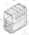
- FIG. 1 is a view for explaining a battery pack and a battery pack assembly guide jig according to an embodiment of the present disclosure.
- a battery pack 1 may be provided, as an energy source, in a vehicle such as an electric vehicle or a hybrid vehicle.
- the battery pack 1 may be mounted on a body of the vehicle, and may be mounted on a lower portion of the body of the vehicle.
- the battery pack 1 may be possible to be mounted on a position of the conventional oil tank in place of an oil tank.
- the battery pack 1 may be mounted on a position of an oil tank in a previous general truck or general bus in place of an oil tank
- Such a battery pack 1 may be configured to include a battery module 10, a case tray 20 supporting the battery module 10, and a case cover 30 that is coupled to the case tray 20 so that the battery module 10 is packaged.
- the battery module 10 may be provided in at least one or in plurality.
- the battery module 10 may include a battery cell 15.
- the battery cell 15 may be provided in at least one or more. Such a battery cell 15 may be provided, as a secondary battery, as a pouch type secondary battery, a square type secondary battery, or a cylindrical type secondary battery. Hereinafter, in the present embodiment, the battery cell 15 will be described as being provided as a pouch type secondary battery.
- the case tray 20 may support the battery module 10, and may be mounted on machine or instrument that uses the battery pack 1 as an energy source.
- the case tray 20 may be mounted on a vehicle such as an electric vehicle.
- the case cover 30 may be coupled to the case tray 20 through a fastening member, etc. so that the battery module 20 may be packaged. Such coupling of the case cover 30 and the case tray 20 through the fastening member, etc. may be performed in the edge of the case cover 30 and the edge of the case tray 20.
- the assembly accuracy between the case tray 20 and the case cover 30 may be further required.
- a battery pack assembly guide jig 50 for guiding the assembly of the battery pack 1 may be provided.
- the battery pack assembly guide jig 50 may support the case tray 20 and the case cover 30 when the case tray 20 and the case cover 30 of the battery pack 1 are coupled to each other.
- such a battery pack assembly guide jig 50 may integrally support the case cover 30 and the case tray 20 to make the edge of the case cover 30 and the edge of the case tray 20 smoothly face and contact each other at a correct position while suppressing the spring back phenomenon of the case cover 30 and the case tray 20.
- FIG. 2 is a front perspective view of the battery pack assembly guide jig of FIG. 1
- FIG. 3 is a rear perspective view of the battery pack assembly guide jig of FIG. 2
- FIG. 4 is a view for explaining a first guiding unit of the battery pack assembly guide jig of FIG. 2
- FIG. 5 is a view for explaining a second guiding unit of the battery pack assembly guide jig of FIG. 2 .
- the battery pack assembly guide jig 50 may include a first guiding unit 100 and a second guiding unit 200.
- the first guiding unit 100 may temporarily fix one side edge (-Y-axis direction) of the case tray 20 (see FIG. 1 ) and one side edge (-Y-axis direction) of the case cover 30 (see FIG. 1 ).
- Such a first guiding unit 100 may be provided as a pair.
- the pair of first guiding units 100 may be disposed to be spaced apart from each other by a predetermined distance in a height direction (Z-axis direction) of the battery pack 1 (see FIG. 1 ).
- the first guiding unit 100 may temporarily fix the case tray 20 (see FIG. 1 ) and the case cover 30 (see FIG. 1 ) in up and down direction in the height direction (Z-axis direction) of the battery pack 1, thereby securing a more stable bearing capacity.
- Such a pair of first guiding units 100 may include, respectively, a first guiding body 110, a first tray insertion portion 130, and a first cover insertion portion 150.
- the first guiding body 110 may have a predetermined shape and may be provided in an approximately hexahedral shape. This is only an example, and the shape of the first guiding body 110 may be provided in other shapes as long as the first guiding unit 100 may temporarily fix the edge of the case tray 20 and the edge of the case cover 30.
- the first tray insertion portion 130 may be provided in the first guiding body 100, and one side edge (-Y-axis direction) of the case tray 20 may be inserted therein.
- Such a first tray insertion portion 130 may be formed by a predetermined depth from a rear surface (-X-axis direction) of the first guiding body 110, and may be formed long in the up and down direction (Z-axis direction) of the first guide body 110.
- the first cover inserting portion 150 may be provided in the first guiding body 110 to be spaced apart from the first tray inserting portion 130 by a predetermined distance, and one side edge of the case cover 30 (-Y-axis direction) may be inserted therein.
- Such a first cover insertion portion 150 may be formed by a predetermined depth from the rear surface (-X-axis direction) of the first guiding body 110, and may be formed long in the up and down direction (Z-axis direction) of the first guide body 110.
- An upper end 152 (+Z-axis direction) of the first cover insertion portion 150 may be formed to have a larger width than that of a lower end 154 (-Z-axis direction) of the first cover inserting portion 150. Accordingly, the first cover insertion portion 150 may be provided to have a width tapered from an upper side to a lower side in the height direction (Z-axis direction) the first cover insertion portion 150.
- the second guiding unit 200 may be spaced apart from the first guiding unit 100 by a predetermined distance, and may temporarily fix the other side edge (+Y-axis direction) of the case tray 20 and the other side edge (+Y-axis direction) of the case cover 30.
- the pair of second guiding units 200 may be disposed to be spaced apart from each other by a predetermined distance in the height direction (Z-axis direction) of the battery pack 1 (see FIG. 1 ).
- the second guiding unit 200 may temporarily fix the case tray 20 (see FIG. 1 ) and the case cover 30 (see FIG. 1 ) in the up and down direction in the height direction (Z-axis direction) of the battery pack 1, thereby securing a more stable bearing capacity.
- Such a pair of second guiding units 200 may include, respectively, a second guiding body 210, a second tray insertion portion 230, and a second cover insertion portion 250.
- the second guiding body 210 may have a predetermined shape, and may be provided in an approximately hexahedral shape. This is only an example, and the shape of the second guiding body 210 may be provided in other shapes as long as the second guiding body 210 may temporarily fix the edge of the case tray 20 and the edge of the case cover 30.
- the second tray insertion portion 230 may be provided in the second guiding body 100, and the other side edge (+Y-axis direction) of the case tray 20 may be inserted therein.
- Such a second tray insertion portion 230 may be formed by a predetermined depth from a rear surface (-X-axis direction) of the second guiding body 210, and may be formed long in the up and down direction (Z-axis direction) of the second guide body 210.
- the second cover insertion portion 250 may be provided on the second guiding body 210 to be spaced apart from the second tray insertion portion 230 by a predetermined distance, and the other side edge (+Y-axis direction) of the case cover 30 may be inserted therein.
- the second cover insertion portion 250 may be formed by a predetermined depth from the rear surface (-X-axis direction) of the second guiding body 210, and may be formed long in the up and down direction (Z-axis direction) of the second guide body 210.
- An upper end 252 (+Z-axis direction) of the second cover insertion portion 250 may be formed to have a larger width than that of a lower end 254 (-Z-axis direction) of the second cover insertion portion 250. Accordingly, the second cover insertion portion 250 may be provided to have a width tapered from an upper side to a lower side in the height direction (Z-axis direction) of the second cover insertion portion 250.
- the battery pack assembly guide jig 50 may include a connection unit 300.
- the connection unit 300 may have a predetermined length, and may connect the first guiding unit 100 and the second guiding unit 200.
- connection unit 300 may include a first connection member 310 and a second connection member 330.
- the first connection member 310 may be formed by a predetermined length and may connect the first guiding unit 100 and the second guiding unit 200. Such a first connection member 310 may be mounted on the first guiding body 110 of the first guiding unit 100 and the second guiding body 210 of the second guiding unit 200 disposed on the upper side in the height direction (Z-axis direction) of the battery pack 1.
- the second connection member 330 may be formed by a predetermined length, may be spaced apart from the first connection member 310 by a predetermined distance in the height direction (Z-axis direction) of the battery pack 1, and may connect the first guiding unit 100 and the second guiding unit 200 to each other.
- Such a second connection member 330 may be mounted on the first guiding body 110 of the first guiding unit 100 and the second guiding body 210 of the second guiding unit 200 disposed on the lower side in the height direction (Z-axis direction) of the battery pack 1.
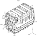
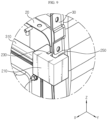
- FIGS. 6 to 10 are views for explaining assembly guiding mechanism of the battery pack assembly guide jig when a case tray and a case cover of the battery pack of FIG. 1 are coupled to each other.
- a manufacturer, etc. may make the battery module 10 seated in the case tray 20 of the battery pack 1 and then couple the case cover 30 with the case tray 20 for packaging of the battery module 10.
- the battery pack assembly guide jig 50 may be temporarily fixed to the case tray 20.
- one side edge (-Y-axis direction) and the other side edge (+Y-axis direction) of the case tray 20 may be respectively inserted into the first guiding unit 100 and the second guiding unit 200 of the battery pack assembly guide jig 50.
- one side edge (-Y-axis direction) of the case tray 20 may be inserted into a first tray insertion groove 130 of the first guiding unit 100, and the other side edge (+Y-axis direction) of the case tray 20 may be inserted into a second tray insertion groove 230 of the second guiding unit 200.
- the case cover 30 may slide downward (-Z-axis direction) toward the case tray 20.
- one side edge (-Y-axis direction) and the other side edge (+Y-axis direction) of the case cover 30 may be respectively inserted into and temporarily fixed to the first guiding unit 100 and the second guiding unit 200 of the battery pack assembly guide jig 50.
- one side edge (-Y-axis direction) of the case cover 30 may be inserted into a first cover insertion groove 150 of the first guiding unit 100, and the other side edge (+Y-axis direction) of the case cover 30 may be inserted into a second cover insertion groove 250 of the second guiding unit 200.
- each of the first cover insertion groove 150 and the second cover insertion groove 250 has a width tapered toward the lower end, thereby temporarily fixing and supporting the edge of the case cover 30 more firmly than the downward (-Z-axis direction) sliding after insertion of the case cover 30.
- the manufacturer, etc. may mutually fasten the edges of the case cover 30 and the case tray 20 by using a fastening member, etc.
- the battery pack assembly guide jig 50 integrally fixes and support the edge of the case tray 20 and the edge of the case cover 30, thereby remarkably increasing the fastening accuracy of the fastening member, etc.
- the manufacturer, etc. may separate the battery pack assembly guide jig 50 from the case tray 20 and the case cover 30.
- the manufacturer, etc. may guide the battery pack 10 to a next manufacturing process, etc. to proceed with a subsequent manufacturing process.
- the battery pack assembly guide jig 50 may temporarily fix and support the edge of the case tray 20 and the edge of the case cover 30 more stably, thereby effectively suppressing a spring back phenomenon of the case tray 20 and the case cover 30.
- the battery pack assembly guide jig 50 when the case tray 20 and the case cover 30 are coupled to each other, it is possible to effectively guide the edges of the case tray 20 and the case cover 30 to face each other.
- the fastening accuracy through the fastening member, etc. may be increased, and the entire assembly process time may also be significantly shortened.
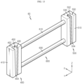
- FIG. 11 is a view for explaining a battery pack assembly guide jig according to another embodiment of the present disclosure
- FIG. 12 is a front perspective view of the battery pack assembly guide jig of FIG. 11
- FIG. 13 is a rear perspective view of the battery pack assembly guide jig of FIG. 12 .
- the battery pack assembly guide jig 60 according to the present embodiment is similar to the battery pack assembly guide jig 50 of the previous embodiment, and thus redundant descriptions of components that are substantially the same as or similar to those of the previous embodiment are omitted.
- differences between the present embodiment and the previous embodiment will be mainly described.
- the battery pack assembly guide jig 60 may include a first guiding unit 400, a second guiding unit 500, and a connection unit 600.
- the first guiding unit 400 may be provided as a single member rather than a pair.
- the first guiding unit 400 may include a first guiding body 410, a first tray insertion portion 430, and a first cover insertion portion 450.
- the first guiding body 410 may be formed to have a longer length in the height direction (Z-axis direction) of the battery pack assembly guide jig 60 than that of the first guiding body 110 of the previous embodiment. This is to more stably support the case tray 20 and the case cover 30 when the case tray 20 and the case cover 30 of the battery pack 1 are coupled to each other.
- the first tray insertion portion 430 and the first cover insertion portion 450 may have longer lengths than those of the first tray insertion portion 130 and the first cover insertion portion 150 of the previous embodiment.
- an upper end 452 (+Z-axis direction) of the first cover insertion portion 450 may have a larger width than that of a lower end 454 (-Z-axis direction) of the first cover insertion portion 450 as in the previous embodiment.
- the second guiding unit 500 may include a second guiding body 510, a second tray insertion portion 530, and a second cover insertion portion 550.
- the second guiding body 510 may be formed to have a longer length in the height direction (Z-axis direction) of the battery pack assembly guide jig 60 than that of the second guiding body 210 of the previous embodiment. This is to more stably support the case tray 20 and the case cover 30 when the case tray 20 and the case cover 30 of the battery pack 1 are coupled to each other.
- the second tray insertion portion 530 and the second cover insertion portion 550 may have longer lengths than those of the second tray insertion portion 230 and the second cover insertion portion 250 of the previous embodiment.
- an upper end 552 (+Z-axis direction) of the second cover insertion portion 550 may have a larger width than that of a lower end 554 (-Z-axis direction) of the second cover insertion portion 550, as in the previous embodiment.
- the connection unit 600 may include a first connection member 610 and a second connection member 630.
- the first connection member 610 and the second connection member 630 are similar to those of the previous embodiment, and thus redundant descriptions thereof will be omitted below.
- the first guiding unit 400 and the second guiding unit 500 may be provided as a single member.
- the battery pack assembly guide jig 60 may reduce manufacturing cost or time, thereby securing cost competitiveness of the battery pack assembly guide jig 60.
- the battery pack assembly guide jigs 50 and 60 capable of improving assembly properties may be provided.
- the battery pack assembly guide jigs 50 and 60 capable of preventing product defects may be provided.
Landscapes
- Chemical & Material Sciences (AREA)
- Chemical Kinetics & Catalysis (AREA)
- Electrochemistry (AREA)
- General Chemical & Material Sciences (AREA)
- Engineering & Computer Science (AREA)
- Manufacturing & Machinery (AREA)
- Battery Mounting, Suspending (AREA)
Abstract
Description
- The present disclosure relates to a battery pack assembly guide jig, and more particularly to, a battery pack assembly guide jig to guide the assembly of a battery pack.
- The present application claims priority to
Korean Patent Application No. 10-2020-0131940 filed on October 13, 2020 - Secondary batteries that have high ease of application according to product groups and have electrical characteristics such as high energy density, etc. are universally applied to not only portable devices, but also electric vehicles (EVs) or hybrid vehicles (HEVs) driven by an electric drive source. These secondary batteries are attracting attention as a new energy source for improving eco-friendliness and energy efficiency in that not only the primary advantage of being able to dramatically reduce the use of fossil fuels but also the fact that no by-products are generated from the use of energy.
- The types of secondary batteries that are currently widely used include a lithium ion battery, a lithium polymer battery, a nickel cadmium battery, a nickel hydrogen battery, a nickel zinc battery, etc. The operating voltage of such a unit secondary battery cell, that is, a unit battery cell, is about 2.5 V to about 4.5 V. Accordingly, when a higher output voltage is required, a plurality of battery cells are connected in series to configure a battery pack. In addition, a plurality of battery cells are connected in parallel to configure a battery pack according to the charge/discharge capacity required for the battery pack. Accordingly, the number of battery cells included in the battery pack may be set in various ways according to a required output voltage or charge/discharge capacity.
- Meanwhile, when a battery pack is configured by connecting a plurality of battery cells in series/parallel, a method of configuring the battery pack by first configuring a battery module including at least one battery cell, and adding other components using the at least one battery module is common.
- The conventional battery pack is configured to include a case tray supporting a battery module and a case cover coupled to the case cover so that the battery module may be packaged.
- In the case of an assembly process of the case tray and the case cover of the conventional battery pack, the edge of the case tray and the edge of the case cover face each other, and then are fastened by using a fastening member, etc. so that the case tray and the case cover are coupled to each other.
- However, during such a conventional assembly process of the case tray and the case cover, due to a spring back phenomenon of the case tray and the case cover, a problem that it is difficult to have the edges face each other occurs frequently. Accordingly, there is a problem that the entire assembly process is less efficient and leads to product defects such as an erroneous assembly, etc.
- Therefore, it is required to seek a solution to prevent the product defects and improve assembly properties during the assembly process of the case tray and case cover of the battery pack.
- The present disclosure is designed to solve the problems of the related art, and therefore the present disclosure is directed to providing a battery pack assembly guide jig capable of improving assembly properties during an assembly process of a case tray and a case cover of a battery pack.
- The present disclosure is also directed to providing a battery pack assembly guide jig capable of preventing product defects during an assembly process of a case tray and a case cover of a battery pack.
- In one aspect of the present disclosure, there is provided a battery pack assembly guide jig for guiding an assembly of a battery pack, wherein the battery pack assembly guide jig is configured to support a case tray and a case cover of the battery pack when the case tray and the case cover are coupled to each other.
- The battery pack assembly guide jig may include a first guiding unit configured to temporarily fix one side edge of the case tray and one side edge of the case cover; and a second guiding unit spaced apart from the first guiding unit by a predetermined distance and configured to temporarily fix the other side edge of the case tray and the other side edge of the case cover.
- The battery pack assembly guide jig may further include a connection unit configured to connect the first guiding unit and the second guiding unit.
- The first guiding unit may be provided in a pair, and the pair of first guiding units may be spaced apart from each other by a predetermined distance in a height direction of the battery pack.
- The second guiding unit may be provided in a pair, and the pair of second guiding units may be spaced apart from each other by a predetermined distance in a height direction of the battery pack.
- The connection unit may include a first connection member formed long by a predetermined length and configured to connect the first guiding unit and the second guiding unit; and a second connection member spaced apart from the first connection member by a predetermined distance in a height direction of the battery pack and configured to connect the first guiding unit and the second guiding unit.
- The first guiding unit may include a first guiding body having a predetermined shape; a first tray insertion portion provided in the first guiding body and into which one side edge of the case tray is inserted; and a first cover insertion portion provided in the first guiding body to be spaced apart from the first tray insertion portion by a predetermined distance and into which one side edge of the case cover is inserted.
- The first tray insertion portion and the first cover insertion portion may be formed by a predetermined depth from the first guiding body and formed long in an up and down direction of the first guiding body.
- The second guiding unit may include a second guiding body having a predetermined shape; a second tray insertion portion provided in the second guiding body and into which the other side edge of the case tray is inserted; and a second cover insertion portion provided in the second guiding body to be spaced apart from the second tray insertion portion by a predetermined distance and into which the other side edge of the case cover is inserted.
- The second tray insertion portion and the second cover insertion portion may be formed by a predetermined depth from the second guiding body and formed long in an up and down direction of the second guiding body.
- According to various embodiments as described above, a battery pack assembly guide jig capable of improving assembly properties during an assembly process of a case tray and a case cover of a battery pack may be provided.
- In addition, according to various embodiments as described above, a battery pack assembly guide jig capable of preventing product defects during an assembly process of a case tray and a case cover of a battery pack may be provided.
- The accompanying drawings illustrate a preferred embodiment of the present disclosure and together with the foregoing disclosure, serve to provide further understanding of the technical features of the present disclosure, and thus, the present disclosure is not construed as being limited to the drawing.
-
FIG. 1 is a view for explaining a battery pack and a battery pack assembly guide jig according to an embodiment of the present disclosure. -
FIG. 2 is a front perspective view of the battery pack assembly guide jig ofFIG. 1 . -
FIG. 3 is a rear perspective view of the battery pack assembly guide jig ofFIG. 2 . -
FIG. 4 is a view for explaining a first guiding unit of the battery pack assembly guide jig ofFIG. 2 . -
FIG. 5 is a view for explaining a second guiding unit of the battery pack assembly guide jig ofFIG. 2 . -
FIGS. 6 to 10 are views for explaining assembly guiding mechanism of the battery pack assembly guide jig when a case tray and a case cover of a battery pack ofFIG. 1 are coupled to each other. -
FIG. 11 is a view for explaining a battery pack assembly guide jig according to another embodiment of the present disclosure. -
FIG. 12 is a front perspective view of the battery pack assembly guide jig ofFIG. 11 . -
FIG. 13 is a rear perspective view of the battery pack assembly guide jig ofFIG. 12 . - Hereinafter, preferred embodiments of the present disclosure will be described in detail with reference to the accompanying drawings. Prior to the description, it should be understood that the terms used in the specification and the appended claims should not be construed as limited to general and dictionary meanings, but interpreted based on the meanings and concepts corresponding to technical aspects of the present disclosure on the basis of the principle that the inventor is allowed to define terms appropriately for the best explanation. Therefore, the description proposed herein is just a preferable example for the purpose of illustrations only, not intended to limit the scope of the disclosure, so it should be understood that other equivalents and modifications could be made thereto without departing from the scope of the disclosure. In addition, in order to help the understanding of the invention, the accompanying drawings are not shown in actual scale, but dimensions of some components may be exaggeratedly shown.
-
FIG. 1 is a view for explaining a battery pack and a battery pack assembly guide jig according to an embodiment of the present disclosure. - Referring to
FIG. 1 , abattery pack 1 may be provided, as an energy source, in a vehicle such as an electric vehicle or a hybrid vehicle. Thebattery pack 1 may be mounted on a body of the vehicle, and may be mounted on a lower portion of the body of the vehicle. - In addition, the
battery pack 1 may be possible to be mounted on a position of the conventional oil tank in place of an oil tank. For example, in the case of an electric (EV) truck or an EV bus, thebattery pack 1 may be mounted on a position of an oil tank in a previous general truck or general bus in place of an oil tank - Such a
battery pack 1 may be configured to include abattery module 10, acase tray 20 supporting thebattery module 10, and acase cover 30 that is coupled to thecase tray 20 so that thebattery module 10 is packaged. - The
battery module 10 may be provided in at least one or in plurality. Thebattery module 10 may include abattery cell 15. - The
battery cell 15 may be provided in at least one or more. Such abattery cell 15 may be provided, as a secondary battery, as a pouch type secondary battery, a square type secondary battery, or a cylindrical type secondary battery. Hereinafter, in the present embodiment, thebattery cell 15 will be described as being provided as a pouch type secondary battery. - The
case tray 20 may support thebattery module 10, and may be mounted on machine or instrument that uses thebattery pack 1 as an energy source. For example, thecase tray 20 may be mounted on a vehicle such as an electric vehicle. - The
case cover 30 may be coupled to the case tray 20 through a fastening member, etc. so that thebattery module 20 may be packaged. Such coupling of thecase cover 30 and the case tray 20 through the fastening member, etc. may be performed in the edge of thecase cover 30 and the edge of the case tray 20. - Upon such coupling of the
case cover 30 and the case tray 20, it may be difficult to face the edges of thecase cover 30 and the case tray 20 due to a spring back phenomenon. Accordingly, fastening of the fastening member, etc. is also difficult, and a problem such as an erroneous assembly may occur. - In particular, in the case of the EV truck or the EV bus, when the
battery pack 1 is mounted on a position of an oil tank in a previous general truck or general bus in place of the oil tank, the assembly accuracy between thecase tray 20 and the case cover 30 may be further required. - To this end, in the present embodiment, a battery pack
assembly guide jig 50 for guiding the assembly of thebattery pack 1 may be provided. - The battery pack
assembly guide jig 50 may support thecase tray 20 and the case cover 30 when thecase tray 20 and the case cover 30 of thebattery pack 1 are coupled to each other. - When the
case tray 20 and the case cover 30 of thebattery pack 1 are coupled to each other, such a battery packassembly guide jig 50 may integrally support thecase cover 30 and thecase tray 20 to make the edge of thecase cover 30 and the edge of thecase tray 20 smoothly face and contact each other at a correct position while suppressing the spring back phenomenon of thecase cover 30 and thecase tray 20. - Hereinafter, the battery pack
assembly guide jig 50 according to the present embodiment will be described in more detail. -
FIG. 2 is a front perspective view of the battery pack assembly guide jig ofFIG. 1 ,FIG. 3 is a rear perspective view of the battery pack assembly guide jig ofFIG. 2 ,FIG. 4 is a view for explaining a first guiding unit of the battery pack assembly guide jig ofFIG. 2 , andFIG. 5 is a view for explaining a second guiding unit of the battery pack assembly guide jig ofFIG. 2 . - Referring to
FIGS. 2 to 5 , the battery packassembly guide jig 50 may include afirst guiding unit 100 and asecond guiding unit 200. - The
first guiding unit 100 may temporarily fix one side edge (-Y-axis direction) of the case tray 20 (seeFIG. 1 ) and one side edge (-Y-axis direction) of the case cover 30 (seeFIG. 1 ). - Such a
first guiding unit 100 may be provided as a pair. - The pair of first guiding
units 100 may be disposed to be spaced apart from each other by a predetermined distance in a height direction (Z-axis direction) of the battery pack 1 (seeFIG. 1 ). - In the present embodiment, the
first guiding unit 100 may temporarily fix the case tray 20 (seeFIG. 1 ) and the case cover 30 (seeFIG. 1 ) in up and down direction in the height direction (Z-axis direction) of thebattery pack 1, thereby securing a more stable bearing capacity. - Such a pair of first guiding
units 100 may include, respectively, afirst guiding body 110, a firsttray insertion portion 130, and a firstcover insertion portion 150. - The
first guiding body 110 may have a predetermined shape and may be provided in an approximately hexahedral shape. This is only an example, and the shape of thefirst guiding body 110 may be provided in other shapes as long as thefirst guiding unit 100 may temporarily fix the edge of thecase tray 20 and the edge of thecase cover 30. - The first
tray insertion portion 130 may be provided in thefirst guiding body 100, and one side edge (-Y-axis direction) of thecase tray 20 may be inserted therein. Such a firsttray insertion portion 130 may be formed by a predetermined depth from a rear surface (-X-axis direction) of thefirst guiding body 110, and may be formed long in the up and down direction (Z-axis direction) of thefirst guide body 110. - The first
cover inserting portion 150 may be provided in thefirst guiding body 110 to be spaced apart from the firsttray inserting portion 130 by a predetermined distance, and one side edge of the case cover 30 (-Y-axis direction) may be inserted therein. - Such a first
cover insertion portion 150 may be formed by a predetermined depth from the rear surface (-X-axis direction) of thefirst guiding body 110, and may be formed long in the up and down direction (Z-axis direction) of thefirst guide body 110. - An upper end 152 (+Z-axis direction) of the first
cover insertion portion 150 may be formed to have a larger width than that of a lower end 154 (-Z-axis direction) of the firstcover inserting portion 150. Accordingly, the firstcover insertion portion 150 may be provided to have a width tapered from an upper side to a lower side in the height direction (Z-axis direction) the firstcover insertion portion 150. - The
second guiding unit 200 may be spaced apart from thefirst guiding unit 100 by a predetermined distance, and may temporarily fix the other side edge (+Y-axis direction) of thecase tray 20 and the other side edge (+Y-axis direction) of thecase cover 30. - The pair of second guiding
units 200 may be disposed to be spaced apart from each other by a predetermined distance in the height direction (Z-axis direction) of the battery pack 1 (seeFIG. 1 ). - In the present embodiment, the
second guiding unit 200 may temporarily fix the case tray 20 (seeFIG. 1 ) and the case cover 30 (seeFIG. 1 ) in the up and down direction in the height direction (Z-axis direction) of thebattery pack 1, thereby securing a more stable bearing capacity. - Such a pair of second guiding
units 200 may include, respectively, asecond guiding body 210, a secondtray insertion portion 230, and a secondcover insertion portion 250. - The
second guiding body 210 may have a predetermined shape, and may be provided in an approximately hexahedral shape. This is only an example, and the shape of thesecond guiding body 210 may be provided in other shapes as long as thesecond guiding body 210 may temporarily fix the edge of thecase tray 20 and the edge of thecase cover 30. - The second
tray insertion portion 230 may be provided in thesecond guiding body 100, and the other side edge (+Y-axis direction) of thecase tray 20 may be inserted therein. Such a secondtray insertion portion 230 may be formed by a predetermined depth from a rear surface (-X-axis direction) of thesecond guiding body 210, and may be formed long in the up and down direction (Z-axis direction) of thesecond guide body 210. - The second
cover insertion portion 250 may be provided on thesecond guiding body 210 to be spaced apart from the secondtray insertion portion 230 by a predetermined distance, and the other side edge (+Y-axis direction) of the case cover 30 may be inserted therein. - The second
cover insertion portion 250 may be formed by a predetermined depth from the rear surface (-X-axis direction) of thesecond guiding body 210, and may be formed long in the up and down direction (Z-axis direction) of thesecond guide body 210. - An upper end 252 (+Z-axis direction) of the second
cover insertion portion 250 may be formed to have a larger width than that of a lower end 254 (-Z-axis direction) of the secondcover insertion portion 250. Accordingly, the secondcover insertion portion 250 may be provided to have a width tapered from an upper side to a lower side in the height direction (Z-axis direction) of the secondcover insertion portion 250. - The battery pack
assembly guide jig 50 may include aconnection unit 300. - The
connection unit 300 may have a predetermined length, and may connect thefirst guiding unit 100 and thesecond guiding unit 200. - Such a
connection unit 300 may include afirst connection member 310 and asecond connection member 330. - The
first connection member 310 may be formed by a predetermined length and may connect thefirst guiding unit 100 and thesecond guiding unit 200. Such afirst connection member 310 may be mounted on thefirst guiding body 110 of thefirst guiding unit 100 and thesecond guiding body 210 of thesecond guiding unit 200 disposed on the upper side in the height direction (Z-axis direction) of thebattery pack 1. - The
second connection member 330 may be formed by a predetermined length, may be spaced apart from thefirst connection member 310 by a predetermined distance in the height direction (Z-axis direction) of thebattery pack 1, and may connect thefirst guiding unit 100 and thesecond guiding unit 200 to each other. - Such a
second connection member 330 may be mounted on thefirst guiding body 110 of thefirst guiding unit 100 and thesecond guiding body 210 of thesecond guiding unit 200 disposed on the lower side in the height direction (Z-axis direction) of thebattery pack 1. - Hereinafter, detailed assembly guiding mechanism of the battery pack
assembly guide jig 50 according to the present embodiment will be described in more detail. -
FIGS. 6 to 10 are views for explaining assembly guiding mechanism of the battery pack assembly guide jig when a case tray and a case cover of the battery pack ofFIG. 1 are coupled to each other. - Referring to
FIGS. 6 to 10 , a manufacturer, etc. may make thebattery module 10 seated in thecase tray 20 of thebattery pack 1 and then couple the case cover 30 with thecase tray 20 for packaging of thebattery module 10. - In a coupling process of the
case tray 20 and thecase cover 30, first, the battery packassembly guide jig 50 may be temporarily fixed to thecase tray 20. - Specifically, one side edge (-Y-axis direction) and the other side edge (+Y-axis direction) of the
case tray 20 may be respectively inserted into thefirst guiding unit 100 and thesecond guiding unit 200 of the battery packassembly guide jig 50. - More specifically, one side edge (-Y-axis direction) of the
case tray 20 may be inserted into a firsttray insertion groove 130 of thefirst guiding unit 100, and the other side edge (+Y-axis direction) of thecase tray 20 may be inserted into a secondtray insertion groove 230 of thesecond guiding unit 200. - Thereafter, in the up and down direction (Z-axis direction) of the
battery pack 1, the case cover 30 may slide downward (-Z-axis direction) toward thecase tray 20. - According to the downward (-Z-axis direction) sliding of the
case cover 30, one side edge (-Y-axis direction) and the other side edge (+Y-axis direction) of the case cover 30 may be respectively inserted into and temporarily fixed to thefirst guiding unit 100 and thesecond guiding unit 200 of the battery packassembly guide jig 50. - More specifically, one side edge (-Y-axis direction) of the case cover 30 may be inserted into a first
cover insertion groove 150 of thefirst guiding unit 100, and the other side edge (+Y-axis direction) of the case cover 30 may be inserted into a secondcover insertion groove 250 of thesecond guiding unit 200. - In the case of the first
cover insertion groove 150 and the secondcover insertion groove 250, since the upper end has a large width than the lower end, according to the downward (-Z-axis direction) sliding of thecase cover 30, when both edges of the case cover 30 are respectively inserted into the firstcover insertion groove 150 and the secondcover insertion groove 250, a problem such as non-insertion or an erroneous insertion may be effectively prevented. - In addition, each of the first
cover insertion groove 150 and the secondcover insertion groove 250 has a width tapered toward the lower end, thereby temporarily fixing and supporting the edge of the case cover 30 more firmly than the downward (-Z-axis direction) sliding after insertion of thecase cover 30. - When the downward (-Z-axis direction) sliding of the case cover 30 is completed, the manufacturer, etc., may mutually fasten the edges of the
case cover 30 and thecase tray 20 by using a fastening member, etc. - In the present embodiment, upon fastening of such a fastening member, etc., the battery pack
assembly guide jig 50 integrally fixes and support the edge of thecase tray 20 and the edge of thecase cover 30, thereby remarkably increasing the fastening accuracy of the fastening member, etc. - When the coupling of the
case tray 20 and the case cover 30 through the fastening member, etc. is completed, the manufacturer, etc. may separate the battery packassembly guide jig 50 from thecase tray 20 and thecase cover 30. - Thereafter, the manufacturer, etc. may guide the
battery pack 10 to a next manufacturing process, etc. to proceed with a subsequent manufacturing process. - As such, when the
case tray 20 and the case cover 30 of thebattery pack 10 are coupled to each other, the battery packassembly guide jig 50 according to the present embodiment may temporarily fix and support the edge of thecase tray 20 and the edge of the case cover 30 more stably, thereby effectively suppressing a spring back phenomenon of thecase tray 20 and thecase cover 30. - Accordingly, in the present embodiment, through the battery pack
assembly guide jig 50, when thecase tray 20 and the case cover 30 are coupled to each other, it is possible to effectively guide the edges of thecase tray 20 and the case cover 30 to face each other. - Therefore, in the present embodiment, through the battery pack
assembly guide jig 50, the fastening accuracy through the fastening member, etc. may be increased, and the entire assembly process time may also be significantly shortened. -
FIG. 11 is a view for explaining a battery pack assembly guide jig according to another embodiment of the present disclosure,FIG. 12 is a front perspective view of the battery pack assembly guide jig ofFIG. 11 , andFIG. 13 is a rear perspective view of the battery pack assembly guide jig ofFIG. 12 . - The battery pack
assembly guide jig 60 according to the present embodiment is similar to the battery packassembly guide jig 50 of the previous embodiment, and thus redundant descriptions of components that are substantially the same as or similar to those of the previous embodiment are omitted. Hereinafter, differences between the present embodiment and the previous embodiment will be mainly described. - Referring to
FIGS. 11 to 13 , the battery packassembly guide jig 60 may include afirst guiding unit 400, asecond guiding unit 500, and aconnection unit 600. - The
first guiding unit 400, unlike the previous embodiment, may be provided as a single member rather than a pair. - The
first guiding unit 400 may include afirst guiding body 410, a firsttray insertion portion 430, and a firstcover insertion portion 450. - The
first guiding body 410 may be formed to have a longer length in the height direction (Z-axis direction) of the battery packassembly guide jig 60 than that of thefirst guiding body 110 of the previous embodiment. This is to more stably support thecase tray 20 and the case cover 30 when thecase tray 20 and the case cover 30 of thebattery pack 1 are coupled to each other. - Accordingly, the first
tray insertion portion 430 and the firstcover insertion portion 450 may have longer lengths than those of the firsttray insertion portion 130 and the firstcover insertion portion 150 of the previous embodiment. - Meanwhile, an upper end 452 (+Z-axis direction) of the first
cover insertion portion 450 may have a larger width than that of a lower end 454 (-Z-axis direction) of the firstcover insertion portion 450 as in the previous embodiment. - The
second guiding unit 500 may include asecond guiding body 510, a secondtray insertion portion 530, and a secondcover insertion portion 550. - The
second guiding body 510 may be formed to have a longer length in the height direction (Z-axis direction) of the battery packassembly guide jig 60 than that of thesecond guiding body 210 of the previous embodiment. This is to more stably support thecase tray 20 and the case cover 30 when thecase tray 20 and the case cover 30 of thebattery pack 1 are coupled to each other. - Accordingly, the second
tray insertion portion 530 and the secondcover insertion portion 550 may have longer lengths than those of the secondtray insertion portion 230 and the secondcover insertion portion 250 of the previous embodiment. - Meanwhile, an upper end 552 (+Z-axis direction) of the second
cover insertion portion 550 may have a larger width than that of a lower end 554 (-Z-axis direction) of the secondcover insertion portion 550, as in the previous embodiment. - The
connection unit 600 may include afirst connection member 610 and asecond connection member 630. - The
first connection member 610 and thesecond connection member 630 are similar to those of the previous embodiment, and thus redundant descriptions thereof will be omitted below. - As such, in the battery pack
assembly guide jig 60 according to the present embodiment, unlike the previous embodiment, thefirst guiding unit 400 and thesecond guiding unit 500 may be provided as a single member. - Accordingly, in the present embodiment, the battery pack
assembly guide jig 60 may reduce manufacturing cost or time, thereby securing cost competitiveness of the battery packassembly guide jig 60. - According to various embodiments as described above, during the assembly process of the
case tray 20 and the case cover 30 of thebattery pack 1, the battery pack assembly guide jigs 50 and 60 capable of improving assembly properties may be provided. - In addition, according to various embodiments as described above, during the assembly process of the
case tray 20 and the case cover 30 of thebattery pack 1, the battery pack assembly guide jigs 50 and 60 capable of preventing product defects may be provided. - The present disclosure has been described in detail. However, it should be understood that the detailed description and specific examples, while indicating preferred embodiments of the disclosure, are given by way of illustration only, since various changes and modifications within the scope of the disclosure will become apparent to those skilled in the art from this detailed description.
Claims (10)
- A battery pack assembly guide jig for guiding an assembly of a battery pack, wherein the battery pack assembly guide jig is configured to support a case tray and a case cover of the battery pack when the case tray and the case cover are coupled to each other.
- The battery pack assembly guide jig of claim 1, comprising:a first guiding unit configured to temporarily fix one side edge of the case tray and one side edge of the case cover; anda second guiding unit spaced apart from the first guiding unit by a predetermined distance and configured to temporarily fix the other side edge of the case tray and the other side edge of the case cover.
- The battery pack assembly guide jig of claim 2, further comprising: a connection unit configured to connect the first guiding unit and the second guiding unit.
- The battery pack assembly guide jig of claim 3,wherein the first guiding unit is provided in a pair, andwherein the pair of first guiding units are spaced apart from each other by a predetermined distance in a height direction of the battery pack.
- The battery pack assembly guide jig of claim 3,wherein the second guiding unit is provided in a pair, andwherein the pair of second guiding units are spaced apart from each other by a predetermined distance in a height direction of the battery pack.
- The battery pack assembly guide jig of claim 3,
wherein the connection unit comprises:a first connection member formed long by a predetermined length and configured to connect the first guiding unit and the second guiding unit; anda second connection member spaced apart from the first connection member by a predetermined distance in a height direction of the battery pack and configured to connect the first guiding unit and the second guiding unit. - The battery pack assembly guide jig of claim 3,
wherein the first guiding unit comprises:a first guiding body having a predetermined shape;a first tray insertion portion provided in the first guiding body and into which one side edge of the case tray is inserted; anda first cover insertion portion provided in the first guiding body to be spaced apart from the first tray insertion portion by a predetermined distance, and into which one side edge of the case cover is inserted. - The battery pack assembly guide jig of claim 7,
wherein the first tray insertion portion and the first cover insertion portion are formed by a predetermined depth from the first guiding body and formed long in an up and down direction of the first guiding body. - The battery pack assembly guide jig of claim 3,
wherein the second guiding unit comprises:a second guiding body having a predetermined shape;a second tray insertion portion provided in the second guiding body and into which the other side edge of the case tray is inserted; anda second cover insertion portion provided in the second guiding body to be spaced apart from the second tray insertion portion by a predetermined distance and into which the other side edge of the case cover is inserted. - The battery pack assembly guide jig of claim 9,
wherein the second tray insertion portion and the second cover insertion portion are formed to a predetermined depth from the second guiding body and formed long in an up and down direction of the second guiding body.
Applications Claiming Priority (2)
| Application Number | Priority Date | Filing Date | Title |
|---|---|---|---|
| KR1020200131940A KR102952459B1 (en) | 2020-10-13 | 2020-10-13 | Battery pack assembly guide jig |
| PCT/KR2021/014150 WO2022080872A1 (en) | 2020-10-13 | 2021-10-13 | Battery pack assembly guide jig |
Publications (3)
| Publication Number | Publication Date |
|---|---|
| EP4231418A1 true EP4231418A1 (en) | 2023-08-23 |
| EP4231418A4 EP4231418A4 (en) | 2024-11-20 |
| EP4231418B1 EP4231418B1 (en) | 2025-12-31 |
Family
ID=81208484
Family Applications (1)
| Application Number | Title | Priority Date | Filing Date |
|---|---|---|---|
| EP21880519.0A Active EP4231418B1 (en) | 2020-10-13 | 2021-10-13 | BATTERY PACKING ARRANGEMENT GUIDE DEVICE |
Country Status (7)
| Country | Link |
|---|---|
| US (1) | US20230282868A1 (en) |
| EP (1) | EP4231418B1 (en) |
| JP (1) | JP7552997B2 (en) |
| KR (1) | KR102952459B1 (en) |
| CN (1) | CN116195114B (en) |
| ES (1) | ES3061738T3 (en) |
| WO (1) | WO2022080872A1 (en) |
Families Citing this family (1)
| Publication number | Priority date | Publication date | Assignee | Title |
|---|---|---|---|---|
| KR102902298B1 (en) | 2022-12-27 | 2025-12-19 | 주식회사 호원 | Cooling panel assembly device for manufacturing battery pack case for electric vehicle and clamping jig applied thereto |
Family Cites Families (17)
| Publication number | Priority date | Publication date | Assignee | Title |
|---|---|---|---|---|
| KR100494491B1 (en) * | 2003-06-09 | 2005-06-10 | 기아자동차주식회사 | Device for receiving a battery for vehicles |
| ITVI20050252A1 (en) * | 2005-10-03 | 2007-04-04 | Franco Stocchiero | ATTACHMENT SYSTEM TO AN ELECTRIC ACCUMULATOR OF A DEVICE FOR HANDLING THAT ACCUMULATOR AND ITS DEVICE AND ACCUMULATOR |
| BR112012031165A2 (en) * | 2010-06-09 | 2016-11-01 | Nissan Motor | battery module |
| JP2013054982A (en) * | 2011-09-06 | 2013-03-21 | Panasonic Corp | Method of fitting lead acid battery |
| KR102037209B1 (en) * | 2012-12-31 | 2019-11-26 | 에스케이이노베이션 주식회사 | Assembly Jig for Secondary Battery Pack and Assembly Method for Secondary Battery Pack using the Same |
| CN104218196B (en) * | 2013-05-29 | 2016-08-17 | 李文杰 | Battery case and assemble method thereof |
| JP6233071B2 (en) * | 2014-02-05 | 2017-11-22 | 株式会社豊田自動織機 | Battery pack and battery pack manufacturing method |
| JP2016225153A (en) * | 2015-05-29 | 2016-12-28 | セイコーインスツル株式会社 | Electrochemical cell |
| KR101943285B1 (en) * | 2015-10-22 | 2019-01-28 | 닛산 지도우샤 가부시키가이샤 | Battery pack and manufacturing method thereof |
| KR102084152B1 (en) * | 2016-11-04 | 2020-03-03 | 주식회사 엘지화학 | Battery Pack having tray stopper for preventing spring back of Pack cover |
| JP6787148B2 (en) * | 2017-01-23 | 2020-11-18 | 株式会社豊田自動織機 | Battery pack |
| KR102165328B1 (en) * | 2017-06-22 | 2020-10-13 | 주식회사 엘지화학 | Battery pack |
| KR102201332B1 (en) * | 2017-10-24 | 2021-01-08 | 주식회사 엘지화학 | Battery pack and vehicle comprising the same |
| KR102407165B1 (en) * | 2019-01-03 | 2022-06-10 | 주식회사 엘지에너지솔루션 | Battery pack and apparatus for assembling battery pack |
| KR102043115B1 (en) * | 2019-04-25 | 2019-11-27 | 백영진 | Welding apparatus for outer case of secondary battery cell or electrode assembly and welding system for outer case of secondary battery cell |
| KR102812815B1 (en) | 2019-05-14 | 2025-05-28 | 삼성디스플레이 주식회사 | Display device |
| CN211182395U (en) * | 2019-12-23 | 2020-08-04 | 大族激光科技产业集团股份有限公司 | Fixtures and battery assembly equipment |
-
2020
- 2020-10-13 KR KR1020200131940A patent/KR102952459B1/en active Active
-
2021
- 2021-10-13 CN CN202180059327.4A patent/CN116195114B/en active Active
- 2021-10-13 US US18/018,016 patent/US20230282868A1/en active Pending
- 2021-10-13 ES ES21880519T patent/ES3061738T3/en active Active
- 2021-10-13 WO PCT/KR2021/014150 patent/WO2022080872A1/en not_active Ceased
- 2021-10-13 JP JP2023504851A patent/JP7552997B2/en active Active
- 2021-10-13 EP EP21880519.0A patent/EP4231418B1/en active Active
Also Published As
| Publication number | Publication date |
|---|---|
| EP4231418B1 (en) | 2025-12-31 |
| CN116195114A (en) | 2023-05-30 |
| KR20220048723A (en) | 2022-04-20 |
| JP2023535942A (en) | 2023-08-22 |
| EP4231418A4 (en) | 2024-11-20 |
| CN116195114B (en) | 2026-03-17 |
| JP7552997B2 (en) | 2024-09-18 |
| KR102952459B1 (en) | 2026-04-13 |
| ES3061738T3 (en) | 2026-04-07 |
| WO2022080872A1 (en) | 2022-04-21 |
| US20230282868A1 (en) | 2023-09-07 |
Similar Documents
| Publication | Publication Date | Title |
|---|---|---|
| EP3836244B1 (en) | Battery module and battery pack comprising battery module | |
| CN210489710U (en) | Battery module, battery pack including the same, and vehicle including the battery pack | |
| EP4447193A1 (en) | Battery module, battery pack including same battery module, and automobile including same battery pack | |
| EP3305460A1 (en) | Lead welding apparatus, battery module manufactured through same lead welding apparatus, and battery pack comprising same battery module | |
| EP4019179B1 (en) | Battery module, and battery pack and vehicle including battery module | |
| EP4080656B1 (en) | Battery pack and vehicle comprising battery pack | |
| KR102927317B1 (en) | Transfer jig for loading battery pack into battery rack and battery rack loading method using same | |
| CN112928396B (en) | Battery module, battery pack including the same, and vehicle including the battery pack | |
| EP3731302A1 (en) | Battery module, battery pack comprising same battery module, and vehicle comprising same battery pack | |
| JP7154382B2 (en) | Battery packs and automobiles containing them | |
| US12614817B2 (en) | Battery module comprising bus bar assembly with elastic guiders, and battery pack and vehicle comprising same battery module | |
| EP4231418B1 (en) | BATTERY PACKING ARRANGEMENT GUIDE DEVICE | |
| EP4287374A1 (en) | Battery pack and vehicle comprising same | |
| EP4266469B1 (en) | Battery module, battery pack and vehicle comprising the battery module, and method for manufacturing the battery module | |
| KR102945543B1 (en) | Battery Module Testing Device | |
| EP4576353A1 (en) | Battery cell and, battery module including same, and battery pack including same, and vehicle including same | |
| EP4715986A1 (en) | Battery module, and battery pack and vehicle comprising battery module | |
| EP4661160A1 (en) | Battery pack and vehicle comprising same | |
| KR102165018B1 (en) | Battery module, battery pack comprising the battery module and vehicle comprising the battery pack | |
| EP4708511A1 (en) | Battery pack and vehicle comprising same | |
| KR20250154129A (en) | Tray for activating of battery cell and battery cell produced using the same, and battery pack and vehicle comprising battery cells | |
| CN119381680A (en) | Battery Storage Tray |
Legal Events
| Date | Code | Title | Description |
|---|---|---|---|
| STAA | Information on the status of an ep patent application or granted ep patent |
Free format text: STATUS: THE INTERNATIONAL PUBLICATION HAS BEEN MADE |
|
| PUAI | Public reference made under article 153(3) epc to a published international application that has entered the european phase |
Free format text: ORIGINAL CODE: 0009012 |
|
| STAA | Information on the status of an ep patent application or granted ep patent |
Free format text: STATUS: REQUEST FOR EXAMINATION WAS MADE |
|
| 17P | Request for examination filed |
Effective date: 20230223 |
|
| AK | Designated contracting states |
Kind code of ref document: A1 Designated state(s): AL AT BE BG CH CY CZ DE DK EE ES FI FR GB GR HR HU IE IS IT LI LT LU LV MC MK MT NL NO PL PT RO RS SE SI SK SM TR |
|
| DAV | Request for validation of the european patent (deleted) | ||
| DAX | Request for extension of the european patent (deleted) | ||
| REG | Reference to a national code |
Ref country code: DE Ref legal event code: R079 Free format text: PREVIOUS MAIN CLASS: H01M0050200000 Ipc: H01M0050271000 Ref document number: 602021045704 Country of ref document: DE |
|
| A4 | Supplementary search report drawn up and despatched |
Effective date: 20241018 |
|
| RIC1 | Information provided on ipc code assigned before grant |
Ipc: H01M 50/291 20210101ALI20241014BHEP Ipc: H01M 50/249 20210101ALI20241014BHEP Ipc: H01M 50/20 20210101ALI20241014BHEP Ipc: H01M 50/271 20210101AFI20241014BHEP |
|
| GRAP | Despatch of communication of intention to grant a patent |
Free format text: ORIGINAL CODE: EPIDOSNIGR1 |
|
| STAA | Information on the status of an ep patent application or granted ep patent |
Free format text: STATUS: GRANT OF PATENT IS INTENDED |
|
| INTG | Intention to grant announced |
Effective date: 20251008 |
|
| GRAS | Grant fee paid |
Free format text: ORIGINAL CODE: EPIDOSNIGR3 |
|
| GRAA | (expected) grant |
Free format text: ORIGINAL CODE: 0009210 |
|
| STAA | Information on the status of an ep patent application or granted ep patent |
Free format text: STATUS: THE PATENT HAS BEEN GRANTED |
|
| P01 | Opt-out of the competence of the unified patent court (upc) registered |
Free format text: CASE NUMBER: UPC_APP_0012158_4231418/2025 Effective date: 20251105 |
|
| AK | Designated contracting states |
Kind code of ref document: B1 Designated state(s): AL AT BE BG CH CY CZ DE DK EE ES FI FR GB GR HR HU IE IS IT LI LT LU LV MC MK MT NL NO PL PT RO RS SE SI SK SM TR |
|
| REG | Reference to a national code |
Ref country code: CH Ref legal event code: F10 Free format text: ST27 STATUS EVENT CODE: U-0-0-F10-F00 (AS PROVIDED BY THE NATIONAL OFFICE) Effective date: 20251231 Ref country code: GB Ref legal event code: FG4D |
|
| REG | Reference to a national code |
Ref country code: DE Ref legal event code: R096 Ref document number: 602021045704 Country of ref document: DE |
|
| REG | Reference to a national code |
Ref country code: IE Ref legal event code: FG4D |
|
| REG | Reference to a national code |
Ref country code: ES Ref legal event code: FG2A Ref document number: 3061738 Country of ref document: ES Kind code of ref document: T3 Effective date: 20260407 |
|
| REG | Reference to a national code |
Ref country code: LT Ref legal event code: MG9D |
|
| PG25 | Lapsed in a contracting state [announced via postgrant information from national office to epo] |
Ref country code: NO Free format text: LAPSE BECAUSE OF FAILURE TO SUBMIT A TRANSLATION OF THE DESCRIPTION OR TO PAY THE FEE WITHIN THE PRESCRIBED TIME-LIMIT Effective date: 20260331 |
|
| PG25 | Lapsed in a contracting state [announced via postgrant information from national office to epo] |
Ref country code: FI Free format text: LAPSE BECAUSE OF FAILURE TO SUBMIT A TRANSLATION OF THE DESCRIPTION OR TO PAY THE FEE WITHIN THE PRESCRIBED TIME-LIMIT Effective date: 20251231 Ref country code: HR Free format text: LAPSE BECAUSE OF FAILURE TO SUBMIT A TRANSLATION OF THE DESCRIPTION OR TO PAY THE FEE WITHIN THE PRESCRIBED TIME-LIMIT Effective date: 20251231 |
|
| PG25 | Lapsed in a contracting state [announced via postgrant information from national office to epo] |
Ref country code: RS Free format text: LAPSE BECAUSE OF FAILURE TO SUBMIT A TRANSLATION OF THE DESCRIPTION OR TO PAY THE FEE WITHIN THE PRESCRIBED TIME-LIMIT Effective date: 20260331 |
|
| PG25 | Lapsed in a contracting state [announced via postgrant information from national office to epo] |
Ref country code: LV Free format text: LAPSE BECAUSE OF FAILURE TO SUBMIT A TRANSLATION OF THE DESCRIPTION OR TO PAY THE FEE WITHIN THE PRESCRIBED TIME-LIMIT Effective date: 20251231 |