EP4231400A1 - Smart high-temperature aging system - Google Patents
Smart high-temperature aging system Download PDFInfo
- Publication number
- EP4231400A1 EP4231400A1 EP22837948.3A EP22837948A EP4231400A1 EP 4231400 A1 EP4231400 A1 EP 4231400A1 EP 22837948 A EP22837948 A EP 22837948A EP 4231400 A1 EP4231400 A1 EP 4231400A1
- Authority
- EP
- European Patent Office
- Prior art keywords
- battery cell
- temperature
- high temperature
- temperature aging
- cell tray
- Prior art date
- Legal status (The legal status is an assumption and is not a legal conclusion. Google has not performed a legal analysis and makes no representation as to the accuracy of the status listed.)
- Pending
Links
Images


Classifications
-
- H—ELECTRICITY
- H01—ELECTRIC ELEMENTS
- H01M—PROCESSES OR MEANS, e.g. BATTERIES, FOR THE DIRECT CONVERSION OF CHEMICAL ENERGY INTO ELECTRICAL ENERGY
- H01M10/00—Secondary cells; Manufacture thereof
- H01M10/04—Construction or manufacture in general
-
- B—PERFORMING OPERATIONS; TRANSPORTING
- B65—CONVEYING; PACKING; STORING; HANDLING THIN OR FILAMENTARY MATERIAL
- B65D—CONTAINERS FOR STORAGE OR TRANSPORT OF ARTICLES OR MATERIALS, e.g. BAGS, BARRELS, BOTTLES, BOXES, CANS, CARTONS, CRATES, DRUMS, JARS, TANKS, HOPPERS, FORWARDING CONTAINERS; ACCESSORIES, CLOSURES, OR FITTINGS THEREFOR; PACKAGING ELEMENTS; PACKAGES
- B65D25/00—Details of other kinds or types of rigid or semi-rigid containers
- B65D25/02—Internal fittings
- B65D25/10—Devices to locate articles in containers
-
- B—PERFORMING OPERATIONS; TRANSPORTING
- B65—CONVEYING; PACKING; STORING; HANDLING THIN OR FILAMENTARY MATERIAL
- B65G—TRANSPORT OR STORAGE DEVICES, e.g. CONVEYORS FOR LOADING OR TIPPING, SHOP CONVEYOR SYSTEMS OR PNEUMATIC TUBE CONVEYORS
- B65G1/00—Storing articles, individually or in orderly arrangement, in warehouses or magazines
- B65G1/02—Storage devices
- B65G1/04—Storage devices mechanical
- B65G1/0407—Storage devices mechanical using stacker cranes
-
- G—PHYSICS
- G06—COMPUTING OR CALCULATING; COUNTING
- G06N—COMPUTING ARRANGEMENTS BASED ON SPECIFIC COMPUTATIONAL MODELS
- G06N3/00—Computing arrangements based on biological models
- G06N3/02—Neural networks
- G06N3/04—Architecture, e.g. interconnection topology
- G06N3/044—Recurrent networks, e.g. Hopfield networks
-
- G—PHYSICS
- G06—COMPUTING OR CALCULATING; COUNTING
- G06N—COMPUTING ARRANGEMENTS BASED ON SPECIFIC COMPUTATIONAL MODELS
- G06N3/00—Computing arrangements based on biological models
- G06N3/02—Neural networks
- G06N3/04—Architecture, e.g. interconnection topology
- G06N3/0464—Convolutional networks [CNN, ConvNet]
-
- G—PHYSICS
- G06—COMPUTING OR CALCULATING; COUNTING
- G06N—COMPUTING ARRANGEMENTS BASED ON SPECIFIC COMPUTATIONAL MODELS
- G06N3/00—Computing arrangements based on biological models
- G06N3/02—Neural networks
- G06N3/08—Learning methods
-
- H—ELECTRICITY
- H01—ELECTRIC ELEMENTS
- H01M—PROCESSES OR MEANS, e.g. BATTERIES, FOR THE DIRECT CONVERSION OF CHEMICAL ENERGY INTO ELECTRICAL ENERGY
- H01M10/00—Secondary cells; Manufacture thereof
- H01M10/04—Construction or manufacture in general
- H01M10/0404—Machines for assembling batteries
-
- H—ELECTRICITY
- H01—ELECTRIC ELEMENTS
- H01M—PROCESSES OR MEANS, e.g. BATTERIES, FOR THE DIRECT CONVERSION OF CHEMICAL ENERGY INTO ELECTRICAL ENERGY
- H01M10/00—Secondary cells; Manufacture thereof
- H01M10/04—Construction or manufacture in general
- H01M10/049—Processes for forming or storing electrodes in the battery container
-
- H—ELECTRICITY
- H01—ELECTRIC ELEMENTS
- H01M—PROCESSES OR MEANS, e.g. BATTERIES, FOR THE DIRECT CONVERSION OF CHEMICAL ENERGY INTO ELECTRICAL ENERGY
- H01M10/00—Secondary cells; Manufacture thereof
- H01M10/05—Accumulators with non-aqueous electrolyte
- H01M10/052—Li-accumulators
-
- H—ELECTRICITY
- H01—ELECTRIC ELEMENTS
- H01M—PROCESSES OR MEANS, e.g. BATTERIES, FOR THE DIRECT CONVERSION OF CHEMICAL ENERGY INTO ELECTRICAL ENERGY
- H01M10/00—Secondary cells; Manufacture thereof
- H01M10/42—Methods or arrangements for servicing or maintenance of secondary cells or secondary half-cells
- H01M10/44—Methods for charging or discharging
- H01M10/446—Initial charging measures
-
- Y—GENERAL TAGGING OF NEW TECHNOLOGICAL DEVELOPMENTS; GENERAL TAGGING OF CROSS-SECTIONAL TECHNOLOGIES SPANNING OVER SEVERAL SECTIONS OF THE IPC; TECHNICAL SUBJECTS COVERED BY FORMER USPC CROSS-REFERENCE ART COLLECTIONS [XRACs] AND DIGESTS
- Y02—TECHNOLOGIES OR APPLICATIONS FOR MITIGATION OR ADAPTATION AGAINST CLIMATE CHANGE
- Y02E—REDUCTION OF GREENHOUSE GAS [GHG] EMISSIONS, RELATED TO ENERGY GENERATION, TRANSMISSION OR DISTRIBUTION
- Y02E60/00—Enabling technologies; Technologies with a potential or indirect contribution to GHG emissions mitigation
- Y02E60/10—Energy storage using batteries
-
- Y—GENERAL TAGGING OF NEW TECHNOLOGICAL DEVELOPMENTS; GENERAL TAGGING OF CROSS-SECTIONAL TECHNOLOGIES SPANNING OVER SEVERAL SECTIONS OF THE IPC; TECHNICAL SUBJECTS COVERED BY FORMER USPC CROSS-REFERENCE ART COLLECTIONS [XRACs] AND DIGESTS
- Y02—TECHNOLOGIES OR APPLICATIONS FOR MITIGATION OR ADAPTATION AGAINST CLIMATE CHANGE
- Y02P—CLIMATE CHANGE MITIGATION TECHNOLOGIES IN THE PRODUCTION OR PROCESSING OF GOODS
- Y02P70/00—Climate change mitigation technologies in the production process for final industrial or consumer products
- Y02P70/50—Manufacturing or production processes characterised by the final manufactured product
Definitions
- the present invention relates to a smart high temperature aging system for a battery cell.
- secondary batteries capable of being charged and discharged have been widely used as energy sources for wireless mobile devices.
- the secondary batteries are getting attention as energy sources for electric vehicles and hybrid electric vehicles which are proposed as measures to address the air pollution of conventional gasoline and diesel vehicles using fossil fuels. Therefore, types of applications using the secondary batteries are diversifying due to the advantages of the secondary batteries, and it is expected that the secondary batteries are applied to more fields and products in the future than now.
- Secondary batteries may be classified into lithium ion batteries, lithium ion polymer batteries, and lithium polymer batteries according to the composition of an electrode and an electrolyte, and among these batteries, the use of the lithium ion polymer battery, which is less prone to leakage of the electrolyte and easy to manufacture, is increasing.
- the secondary battery is classified into a cylindrical battery in which an electrode assembly is installed in a cylindrical metal can, a prismatic battery in which an electrode assembly is installed in a prismatic metal can, and a pouch-type battery in which an electrode assembly is installed in a pouch-type case of an aluminum laminated sheet.
- the electrode assembly installed in the battery case is formed with a structure of a positive electrode, a negative electrode, and a separator interposed between the positive electrode and the negative electrode and is a power generation element capable of being charged and discharged.
- the electrode assembly is classified into a jelly-roll type electrode assembly in which a separator is interposed between a positive electrode and a negative electrode, which are long sheets coated with an active material, and is wound, and a stack type electrode assembly in which a plurality of positive and negative electrodes, each having a predetermined size, are sequentially stacked with a separator interposed therebetween.
- an activation process is generally performed after electrolyte injection, and in the activation process, a battery cell forms a solid electrolyte interface (SEI) film through initial charging and then metal foreign materials are rapidly eluted through high-temperature aging to prevent a low voltage failure from being generated.
- SEI solid electrolyte interface
- thermometer a temperature of a battery cell in a central portion of the tray is excessively increased due to difficulty in thermal circulation compared to a battery cell in an outer portion. In this case, a phenomenon in which a capacity of the battery cell located in the central portion is degraded due to an irreversible reaction occurs.
- the temperature control is performed by a person, it is difficult to uniformly control the temperature, and since all the work should be performed manually, there is a problem in that a lot of time and money are required.
- An object of the present invention is to provide a smart high temperature aging system provided with an algorithm capable of minimizing a temperature deviation inside a tray during a high temperature aging process.
- a high temperature aging system including a battery cell tray stack in which battery cell trays accommodating a plurality of battery cells inside are stacked in multiple stages, one or more tray racks accommodated inside a high temperature aging chamber and each including a grid-shaped storage space in which the battery cell tray stack is accommodated, a stacker crane configured to transport the battery cell tray to the grid-shaped storage space, a thermal imaging camera installed on the stacker crane and configured to acquire thermal image temperature data on the battery cell tray stack loaded in the grid-shaped storage space, and a controller configured to control a temperature inside the high temperature aging chamber on the basis of the thermal image temperature data.
- the stacker crane may include a mast configured to move in a left-right direction and a loading station installed on the mast and configured to vertically move, and the thermal imaging camera may acquire thermal image temperature data of battery cell trays while moving together when the mast and the loading station are moved.
- One or more heaters and one or more blowing fans may be installed in the high temperature aging chamber to control the temperature inside the high temperature aging chamber.
- the controller may calculate temperatures of a central portion and an outer portion of the battery cell tray stack from the thermal image temperature data and control the temperature inside the high temperature aging chamber on the basis of the calculated temperatures.
- the controller may control the temperature inside the high temperature aging chamber.
- the controller may calculate an average value of the temperature of the central portion of battery cell tray stacks accommodated in the tray rack or an average value of the temperature difference between the central portion and the outer portion of battery cell tray stacks accommodated in the tray rack, and when the calculation result is outside the reference range, the controller may control the temperature of the entire high temperature aging chamber.
- the controller may calculate an average value of the temperature of the central portion of part of battery cell tray stacks accommodated in the tray rack or an average value of the temperature difference between the central portion and the outer portion of part of battery cell tray stacks accommodated in the tray rack, and when the calculation result is outside the reference range, the controller may locally control a temperature of a region in which a corresponding battery cell tray stack is located.
- the control of the temperature inside the high temperature aging chamber may be performed by stopping and restarting one or more of the heaters and the blowing fans or by a combination of the stopping and restarting.
- the controller may stop the operation of the heater and operate the blowing fan.
- the controller may operate the heater and stop the operation of the blowing fan.
- the controller may learn the thermal image temperature data to derive a temperature control algorithm for minimizing a temperature difference between a central portion and an outer portion of the battery cell tray stack.
- the controller may collect the stored thermal image temperature data to configure training data and include artificial intelligence deriving a temperature control algorithm for minimizing the temperature difference between the central portion and the outer portion of the battery cell tray stack from the training data.
- the artificial intelligence may verify validity of the algorithm by comparing a predicted temperature according to the derived temperature control algorithm and the thermal image temperature data of an actual battery cell tray stack and update the training data with the verification result.
- the temperature control algorithm may relate to positions and numbers of the heaters or the blowing fans operating or stopping or may relate to control of an operating time of the heater or the blowing fan.
- the artificial intelligence may be formed of a deep neural network (DNN) for deep learning.
- DNN deep neural network
- a temperature inside a high temperature aging chamber is optimally controlled on the basis of an artificial intelligence algorithm so that, during a high-temperature aging process, a temperature deviation in the tray can be automatically minimized, and thus it is possible to reduce energy consumption and improve the performance of a battery cell.
- the terms "comprising,” “having,” and the like are used to specify the presence of a feature, a number, a step, an operation, a component, an element, or a combination thereof described herein, and they do not preclude the presence or addition of one or more other features, numbers, steps, operations, components, elements, or combinations thereof.
- a portion of a layer, a film, a region, a plate, or the like is referred to as being "on” another portion, this includes not only a case in which the portion is “directly on” another portion but also a case in which still another portion is present between the portion and the other portion.
- a portion of a layer, a film, a region, a plate, or the like is referred to as being "under” another portion, this includes not only a case in which the portion is “directly under” another portion but also a case in which still another portion is present between the portion and the other portion.
- being disposed “on” may include the case of being disposed not only on an upper portion but also on a lower portion.
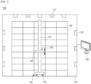
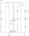
- FIGS. 1 and 2 are schematic diagrams illustrating a high temperature aging system according to the present invention.
- FIG. 5 is a schematic diagram illustrating a process in which the battery cell tray stack is accommodated in a tray rack.
- a high temperature aging system 100 includes a battery cell tray stack 110 in which battery cell trays accommodating a plurality of battery cells inside are stacked in multiple stages therein, one or more tray racks 130 accommodated inside a high temperature aging chamber 120 and each including a grid-shaped storage space in which the battery cell tray stack 110 is accommodated, a stacker crane 140 configured to transport the battery cell tray to the grid-shaped storage space, a thermal imaging camera 150 installed on the stacker crane 140 and configured to acquire thermal image temperature data on the battery cell trays loaded in the grid-shaped storage space, and a controller 160 configured to control a temperature inside the high temperature aging chamber on the basis of the thermal image temperature data.
- the temperature of the high temperature aging chamber is controlled on the basis of the thermal image temperature data, and as will be described below, the temperature control process is performed on the basis of an artificial intelligence algorithm so that energy can be saved and the performance of the battery cell can be improved.
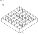
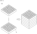
- FIGS. 3 and 4 are schematic diagrams illustrating structures of a battery cell tray and a battery cell tray stack.
- a high temperature aging process is performed in the high temperature aging chamber 120 of which the inside is kept constant at a high temperature, and a plurality of battery cells 1 are subjected to the high temperature aging process at one time.
- the plurality of battery cells 1 are mounted on the battery cell tray 10 in which the plurality of battery cells 1 may be disposed at regular intervals.
- Partition walls may be installed inside the battery cell tray 10 to form grid-shaped storage spaces, and the battery cells 1 may be disposed in the spaces partitioned by the partition walls in a one-to-one manner.
- the battery cell 1 has been illustrated as a cylindrical battery cell, there is no particular limitation on a shape of the battery cell, and various types of battery cells such as a prismatic battery cell or a pouch-type battery cell may be used. In this case, the shape of the partition wall inside the battery cell tray 10 may be changed according to the shape of the battery cell.
- Battery cell trays 10 are stacked in multiple stages as a set for space utilization in the high-temperature aging process to form the battery cell tray stack 110.
- FIG. 4 although it is illustrated that six battery cell trays 10 are stacked to form one battery cell tray stack 110, the number of battery cell trays 10 forming the battery cell tray stack 110 is not particularly limited.
- any material may be used as the battery cell tray 10 as long as it cannot be deformed in a high-temperature aging environment.
- any of metal materials, such as iron and aluminum, and polymer materials such as polycarbonate and acryl may be used.
- one or more tray racks 130 may be provided in the high temperature aging chamber 120 so as to accommodate the battery cell tray stack 110.
- the tray rack 130 has a structure in which grid-shaped storage spaces are formed like a bookshelf to accommodate the battery cell tray stack 110.
- the grid-shaped storage spaces are formed in a predetermined number of rows and stages, and in FIGS. 1 and 5 , although the grid-type storage spaces have been illustrated as being formed in nine rows xfive stages, there is no particular limitation on the sizes and numbers of the grid-type storage spaces.
- the battery cell tray stack 110 is transported to the grid-shaped storage space of the tray rack 130 and then stored at a high temperature for a predetermined time.
- the stacker crane 140 transports the battery cell tray 10 to the grid-shaped storage space.
- the battery cell tray 10 may be transported in the form of an individual battery cell tray or may be stacked in the form of the battery cell tray stack 110 and then transported to the storage space at one time.
- the stacker crane 140 includes a mast 141 moving in a left-right direction and a loading station 142 installed on the mast 141 to vertically move.
- the stacker crane 140 includes a traveling cart 143 configured to move in the left-right direction along one side of the tray rack at a bottom of the high temperature aging chamber 120.
- the traveling cart 143 includes wheels in rolling contact with a floor surface.
- a guide rail (not shown) may be formed in a movement path on which the traveling cart 143 is moved.
- the mast 141 is mounted on the traveling cart 143 in the form of an upright column, supports the loading station, and provides a path on which the loading station 142 vertically moves.
- a guide groove (not shown) for causing the loading station 142 to vertically move may be formed on the mast 141.
- the loading station 142 may have a plate shape and may be a part on which the battery cell tray 10 is mounted during the transport process, and a wheel (not shown) capable of being inserted into a guide groove (not shown) is coupled to a surface coupled to the mast 141 so that the loading station 142 may vertically move on the mast 141 along the guide groove.
- the loading station 142 may vertically move on the mast 141, and the mast 141 may move along the guide rail by the traveling cart 143 in the left-right direction to load or unload the battery cell tray 10 into or from a desired space.
- One or more heaters 121 and one or more blowing fans 122 are installed in the high temperature aging chamber 120 to control a temperature inside the high temperature aging chamber 120.
- the heaters 121 or the blowing fans 122 may be disposed in a uniform pattern along a wall surface and a ceiling of the high temperature aging chamber.
- the blowing fan 122 or the heater 121 of a corresponding battery cell tray stack is operated so that the temperature inside the high temperature aging chamber may be controlled through heat convection.
- the heater 121 and the blowing fan 122 are illustrated as being alternately disposed in FIGS. 1 and 2 , the present invention is not limited thereto, and it is also possible to control the temperature through the blowing fan after placing the heater on one side of the high temperature aging chamber.
- the thermal imaging camera 150 is installed on the stacker crane 140 and acquires thermal image temperature data on the battery cell tray stack 110 loaded in the grid-shaped storage space. Specifically, the thermal imaging camera 150 acquires thermal image temperature data on the battery cell trays while being moved with the mast 141 and the loading station 142 for loading or unloading of the battery cell trays 10.
- the thermal imaging camera 150 may be provided in the form of being coupled to the loading station 142. In this case, as the mast 141 moves in the left-right direction and the loading station 142 vertically moves, the battery cell tray stack 110 may be smoothly photographed.
- the thermal imaging camera 150 photographs a surface of the battery cell tray stack 110 and displays a temperature distribution for each region through color. In this way, it is possible to simultaneously measure the temperatures of two or more points of a measurement target. Further, since a consecutive check of a temperature between each point is possible using the thermal imaging camera 150, it is possible to intuitively or qualitatively grasp a temperature distribution of the entire region of the measurement target. For example, a portion having a relatively low temperature may have a darker color than a portion having a high temperature. Alternatively, respective temperatures in the temperature distribution may be expressed in different colors so that a portion having a high temperature may be expressed as red and a portion having a low temperature may be expressed as relatively blue.
- the thermal imaging camera 150 is used to capture a temperature image of the battery cell tray stack 110, a temperature distribution of the entire measurement target is captured on one screen compared to using a conventional thermometer so that it is possible to measure the temperature of not only one point of the measurement target but also the entire region of the measurement target. As described below, this makes it easier to grasp a temperature difference between the central portion and the outer portion of the battery cell tray stack 110 with one photograph and to easily grasp the temperature of the central portion rather than using a thermometer.
- the controller 160 may be a computing device, and when the thermal image temperature data is acquired by the thermal imaging camera, the controller 160 controls the temperature inside the high temperature aging chamber 120 on the basis of the thermal image temperature data.
- the controller 160 converts a thermal image into a specific temperature value to acquire thermal image temperature data on the outer portion.
- a method in which the controller converts an image captured by the thermal imaging camera into a specific temperature value may be performed by a conventional computing device or program.
- the controller 160 calculates temperatures of the central portion and the outer portion of the battery cell tray stack from the thermal image temperature data.
- the battery cell tray stack 110 in which the battery cell trays are stacked in multiple stages is loaded into the grid-shaped storage space in the tray rack 130.
- thermal circulation is difficult in a central portion A of the battery cell tray stack 110 due to surrounding structures (other battery cell trays) so that a temperature of the central portion A is higher than the outer portion.
- the controller 160 controls the temperature of the high temperature aging chamber on the basis of the temperature data of the central portion and the outer portion of the battery cell tray stack 110.
- the controller 160 controls the temperature of the high temperature aging chamber 120 on the basis of the temperature of the central portion of the battery cell tray stack 110 or a temperature difference between the central portion and the outer portion of the battery cell tray stack 110. Specifically, when the temperature of the central portion of the battery cell tray stack 110 or the temperature difference between the central portion and the outer portion of the battery cell tray stack 110 is outside a reference range, the controller 160 controls the temperature inside the high temperature aging chamber 120.
- the reference range is a temperature range determined to be an appropriate value and may be an item to be appropriately controlled according to specifications of the battery cell, a size of the battery cell, a size of the storage space, and the temperature of the high temperature aging chamber.
- the controller may stop heating the high temperature aging chamber 120 and lower the temperature inside the high temperature aging chamber 120.
- the controller 160 calculates an average value of the temperature of the central portion of all battery cell tray stacks 110 accommodated in the tray rack 130 or an average value of the temperature differences between the central portion and the outer portions of all battery cell tray stacks 110 accommodated in the tray rack 130, and when the calculation result is outside a predetermined range, the controller 160 may control the temperature of the entire high temperature aging chamber 120. In this case, the controller 160 determines whether to control the temperature on the basis of all battery cells in the tray rack 130.
- the controller 160 calculates an average value of the temperature of a central portion of battery cell tray stacks 110 accommodated in the tray rack 130 or an average value of temperature differences between the central portion and outer portions of part battery cell tray stacks 110 accommodated in the tray rack 130, and when the calculated result is outside a reference range, the controller 160 locally controls a temperature of a region in which a corresponding battery cell tray stack 110 is located.
- the controller 160 calculates a temperature of a central portion of the battery cell tray stack 110 located in any one among rows or columns of the tray rack 130 or calculates an average value for temperature differences between the central portion and outer portions of the battery cell tray stack 110, and when the calculated result is outside the reference range, the controller 160 locally controls a temperature of a region in which a corresponding battery cell tray stack 110 is located. Alternatively, when a region with a higher temperature than other regions occurs in some regions of the tray rack 130, a temperature of the corresponding region may be locally controlled.
- the control of the temperature inside the high temperature aging chamber 120 may be performed by stopping and restarting one or more of the heaters 121 and the blowing fans 122 or by a combination of the stopping and restarting. Since the heaters 121 or the blowing fans 122 are arranged in a predetermined pattern along the wall and the ceiling of the high temperature aging chamber 120, by operating or not operating all or some of the heaters 121 and the blowing fans 122 which are installed in the high temperature aging chamber 120, a temperature of a target region may be controlled.
- the controller 160 stops the operation of the heater 121 and operates the blowing fan 122.
- the controller 160 operates the heater 121 and stops the operation of the blowing fan 122.
- the controller 160 operates the heater 121 and stops the operation of the blowing fan 122.
- FIG. 6 is a graph showing a temperature change of battery cell trays over time in the battery cell tray stack.
- a graph shows changes in temperatures measured at various points of the battery cell tray stack constituting the battery cell tray stack 110.
- the maximum temperature of a battery cell tray (a battery cell tray located in the central portion) among the battery cell trays is about 53 °C
- the minimum temperature of a battery cell tray (a battery cell tray located in the outer portion) is about 35 °C so that it can be seen that a temperature difference is 18 °C.
- the temperature inside the high temperature aging chamber is controlled using the blowing fan and the heater so that the temperature difference is gradually reduced.
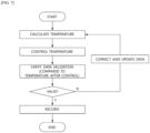
- FIG. 7 is a flowchart illustrating a temperature control algorithm according to the present invention.
- the controller 160 may learn the thermal image temperature data to derive a temperature control algorithm for minimizing the temperature difference between the central portion and the outer portion of the battery cell tray stack 110. In this way, the controller 160 automatically controls a temperature by the operation method as described in the first embodiment to minimize the temperature difference between the central portion and the outer portion through the above algorithm so that less time and money are consumed compared to controlling a temperature by a person, and the temperature difference can be precisely controlled.
- the controller 160 may further include artificial intelligence for temperature control.
- the artificial intelligence collects thermal image temperature data to configure training data and derives a temperature control algorithm for minimizing a temperature difference between the central portion and the outer portion of the battery cell tray stack 110 from the training data.
- the artificial intelligence controls the temperature inside the high temperature aging chamber 120 according to the temperature control algorithm in the same manner as in the first embodiment. That is, the artificial intelligence learns the temperature control algorithm through machine learning or deep learning.
- the high temperature aging system 100 stores thermal image temperature data obtained by performing temperature measurement multiple times.
- the thermal image temperature data may be stored in a classified state according to a measurement time, an initial temperature condition, and specifications of a battery cell, a battery cell tray, a tray rack, and the like and a database (DB) for storing and managing the data may be provided in a separate storage device.
- the DB may be utilized as basic data for configuring the training data.
- the controller 160 may collect the stored thermal image temperature data to configure training data and may include artificial intelligence deriving a temperature control algorithm for minimizing a temperature difference between the central portion and the outer portion of the battery cell tray stack 110 from the training data.
- the artificial intelligence may configure training data by updating a pre-stored DB with a newly measured result.
- the artificial intelligence derives a temperature control algorithm for minimizing the temperature difference between the central portion and the outer portion of the battery cell tray stack 110 from the training data.
- the temperature control algorithm may relate to positions and numbers of the heaters or the blowing fans operating or stopping or may relate to control of the operating time of the heater or the blowing fan.
- the artificial intelligence derives the temperature control algorithm according to data on the position, number, and temperature of the battery cell tray stack of which a temperature is to be controlled.
- the artificial intelligence controls the temperature according to the temperature control algorithm and verifies the validity of the temperature control algorithm.
- the verification process may be performed by comparing a predicted temperature according to the derived temperature control algorithm with the actual thermal image temperature data of the battery cell tray stack 110. For example, after the temperature is controlled according to the derived temperature control algorithm, when the temperature difference between the central portion and the outer portion of the battery cell tray stack 110 deviates from the predicted result, or when there is no significant difference in effect compared to the temperature data according to the existing conditions, the stored training data is corrected and updated. In this case, in consideration of the experimental condition input together with the stored data, it is possible to analyze the cause of an invalid algorithm.
- the temperature control algorithm is machine learned by the artificial intelligence so that the temperature can be precisely and efficiently controlled.
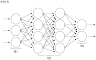
- FIG. 8 is a schematic diagram illustrating a structure of a deep neural network (DNN) for deep learning.
- DNN deep neural network
- the controller 160 may learn the thermal image temperature data to derive a temperature control algorithm for minimizing the temperature difference between the central portion and the outer portion of the battery cell tray stack 110, and the controller 160 may further include artificial intelligence for temperature control.
- the artificial intelligence collects thermal image temperature data to configure training data and derives a temperature control algorithm for minimizing a temperature difference between the central portion and the outer portion of the battery cell tray stack 110 from the training data.
- the artificial intelligence may be formed of a DNN for deep learning.
- the DNN is one among models of machine learning for classifying input data on the basis of learned data and means a system or network which builds one or more layers in one or more computers and performs determination on the basis of a plurality of pieces of data.
- the DNN may include an input layer 161, one or more hidden layers 162, and an output layer 163.
- the training data is input to the input layer 161, the result values calculated through the hidden layer and the output layer are compared with actual values, and then a weight value is updated in reverse. After all learning is finished, information which needs to be predicted is input so that a result value may be obtained.
- the hidden layer 162 may include a convolution layer, a pooling layer, and a fully connected layer.
- the convolution layer may extract a feature map from an image input to the input layer and perform a convolution operation.
- the pooling layer may be connected to the convolution layer to perform sub-sampling on the output of the convolution layer.
- the fully connected layer may be connected to the pooling layer and learns the sub-sampled output of the pooling layer to perform learning according to a category to be output to the output layer 163.
- connection structure of each layer constituting the DNN may be formed by appropriately selecting a known algorithm, and for example, the connection structure may be formed in a convolutional neural network (CNN) structure or a recurrent neural network (RNN) structure.
- CNN convolutional neural network
- RNN recurrent neural network
- the DNN may be implemented in one computer or implemented through a network through which a plurality of computers are connected.
- the learning part 160 inputs the updated training data to the input layer 161 on the DNN.
- the input training data passes through the hidden layer 162 and is output as a final output from the output layer 163.
- the learning part may update a weight value according to a validation result of a prediction result to learn newly updated training data.
- the controller When the learning of the data is completed, the controller newly derives a temperature control algorithm from the learned data and applies the temperature control algorithm to control the temperature inside the high temperature aging chamber. Thereafter, the validity of the algorithm is verified through the temperature control result, and a process of reflecting the temperature control result is automatically repeated so that the temperature of the high temperature aging chamber may be precise controlled.
Landscapes
- Engineering & Computer Science (AREA)
- General Chemical & Material Sciences (AREA)
- Electrochemistry (AREA)
- Chemical Kinetics & Catalysis (AREA)
- Chemical & Material Sciences (AREA)
- Manufacturing & Machinery (AREA)
- Theoretical Computer Science (AREA)
- Physics & Mathematics (AREA)
- Biomedical Technology (AREA)
- Software Systems (AREA)
- Evolutionary Computation (AREA)
- General Health & Medical Sciences (AREA)
- Molecular Biology (AREA)
- Computing Systems (AREA)
- General Engineering & Computer Science (AREA)
- General Physics & Mathematics (AREA)
- Mathematical Physics (AREA)
- Data Mining & Analysis (AREA)
- Computational Linguistics (AREA)
- Biophysics (AREA)
- Artificial Intelligence (AREA)
- Life Sciences & Earth Sciences (AREA)
- Health & Medical Sciences (AREA)
- Mechanical Engineering (AREA)
- Secondary Cells (AREA)
Abstract
Description
- The present invention relates to a smart high temperature aging system for a battery cell.
- The present application claims the benefit of priority based on
Korean Patent Application No. 10-2021-0088257 dated July 6, 2021 - Recently, secondary batteries capable of being charged and discharged have been widely used as energy sources for wireless mobile devices. In addition, the secondary batteries are getting attention as energy sources for electric vehicles and hybrid electric vehicles which are proposed as measures to address the air pollution of conventional gasoline and diesel vehicles using fossil fuels. Therefore, types of applications using the secondary batteries are diversifying due to the advantages of the secondary batteries, and it is expected that the secondary batteries are applied to more fields and products in the future than now.
- Secondary batteries may be classified into lithium ion batteries, lithium ion polymer batteries, and lithium polymer batteries according to the composition of an electrode and an electrolyte, and among these batteries, the use of the lithium ion polymer battery, which is less prone to leakage of the electrolyte and easy to manufacture, is increasing. Generally, according to a shape of a battery case, the secondary battery is classified into a cylindrical battery in which an electrode assembly is installed in a cylindrical metal can, a prismatic battery in which an electrode assembly is installed in a prismatic metal can, and a pouch-type battery in which an electrode assembly is installed in a pouch-type case of an aluminum laminated sheet. The electrode assembly installed in the battery case is formed with a structure of a positive electrode, a negative electrode, and a separator interposed between the positive electrode and the negative electrode and is a power generation element capable of being charged and discharged. The electrode assembly is classified into a jelly-roll type electrode assembly in which a separator is interposed between a positive electrode and a negative electrode, which are long sheets coated with an active material, and is wound, and a stack type electrode assembly in which a plurality of positive and negative electrodes, each having a predetermined size, are sequentially stacked with a separator interposed therebetween.
- In the secondary battery, an activation process is generally performed after electrolyte injection, and in the activation process, a battery cell forms a solid electrolyte interface (SEI) film through initial charging and then metal foreign materials are rapidly eluted through high-temperature aging to prevent a low voltage failure from being generated.
- Since the high-temperature aging is generally performed at a temperature of 60 °C or higher, work should be performed in a space in which the temperature is kept constant. However, according to the related art, after loading trays on which a plurality of battery cells are mounted, temperature control is performed using a general thermometer. However, in this case, among the battery cells in the high temperature aging chamber, a temperature of a battery cell in a central portion of the tray is excessively increased due to difficulty in thermal circulation compared to a battery cell in an outer portion. In this case, a phenomenon in which a capacity of the battery cell located in the central portion is degraded due to an irreversible reaction occurs. In addition, when the temperature control is performed by a person, it is difficult to uniformly control the temperature, and since all the work should be performed manually, there is a problem in that a lot of time and money are required.
-
Korean Patent Laid-Open Application No. 10-2015-0026994 - An object of the present invention is to provide a smart high temperature aging system provided with an algorithm capable of minimizing a temperature deviation inside a tray during a high temperature aging process.
- In one embodiment of the present invention, there is provided a high temperature aging system including a battery cell tray stack in which battery cell trays accommodating a plurality of battery cells inside are stacked in multiple stages, one or more tray racks accommodated inside a high temperature aging chamber and each including a grid-shaped storage space in which the battery cell tray stack is accommodated, a stacker crane configured to transport the battery cell tray to the grid-shaped storage space, a thermal imaging camera installed on the stacker crane and configured to acquire thermal image temperature data on the battery cell tray stack loaded in the grid-shaped storage space, and a controller configured to control a temperature inside the high temperature aging chamber on the basis of the thermal image temperature data.
- The stacker crane may include a mast configured to move in a left-right direction and a loading station installed on the mast and configured to vertically move, and the thermal imaging camera may acquire thermal image temperature data of battery cell trays while moving together when the mast and the loading station are moved.
- One or more heaters and one or more blowing fans may be installed in the high temperature aging chamber to control the temperature inside the high temperature aging chamber.
- The controller may calculate temperatures of a central portion and an outer portion of the battery cell tray stack from the thermal image temperature data and control the temperature inside the high temperature aging chamber on the basis of the calculated temperatures.
- When the temperature of the central portion of the battery cell tray stack or a temperature difference between the central portion and the outer portion of the battery cell tray stack is outside a reference range, the controller may control the temperature inside the high temperature aging chamber.
- The controller may calculate an average value of the temperature of the central portion of battery cell tray stacks accommodated in the tray rack or an average value of the temperature difference between the central portion and the outer portion of battery cell tray stacks accommodated in the tray rack, and when the calculation result is outside the reference range, the controller may control the temperature of the entire high temperature aging chamber.
- The controller may calculate an average value of the temperature of the central portion of part of battery cell tray stacks accommodated in the tray rack or an average value of the temperature difference between the central portion and the outer portion of part of battery cell tray stacks accommodated in the tray rack, and when the calculation result is outside the reference range, the controller may locally control a temperature of a region in which a corresponding battery cell tray stack is located.
- The control of the temperature inside the high temperature aging chamber may be performed by stopping and restarting one or more of the heaters and the blowing fans or by a combination of the stopping and restarting.
- When decreasing the temperature inside the high temperature aging chamber, the controller may stop the operation of the heater and operate the blowing fan.
- When increasing the temperature inside the high temperature aging chamber, the controller may operate the heater and stop the operation of the blowing fan.
- The controller may learn the thermal image temperature data to derive a temperature control algorithm for minimizing a temperature difference between a central portion and an outer portion of the battery cell tray stack.
- The controller may collect the stored thermal image temperature data to configure training data and include artificial intelligence deriving a temperature control algorithm for minimizing the temperature difference between the central portion and the outer portion of the battery cell tray stack from the training data.
- The artificial intelligence may verify validity of the algorithm by comparing a predicted temperature according to the derived temperature control algorithm and the thermal image temperature data of an actual battery cell tray stack and update the training data with the verification result.
- The temperature control algorithm may relate to positions and numbers of the heaters or the blowing fans operating or stopping or may relate to control of an operating time of the heater or the blowing fan.
- The artificial intelligence may be formed of a deep neural network (DNN) for deep learning.
- In accordance with the present invention, a temperature inside a high temperature aging chamber is optimally controlled on the basis of an artificial intelligence algorithm so that, during a high-temperature aging process, a temperature deviation in the tray can be automatically minimized, and thus it is possible to reduce energy consumption and improve the performance of a battery cell.
-
-
FIGS. 1 and2 are schematic diagrams illustrating a high temperature aging system according to the present invention. -
FIGS. 3 and4 are schematic diagrams illustrating structures of a battery cell tray and a battery cell tray stack. -
FIG. 5 is a schematic diagram illustrating a process in which the battery cell tray stack is accommodated in a tray rack. -
FIG. 6 is a graph showing a temperature change of battery cell trays over time in the battery cell tray stack. -
FIG. 7 is a flowchart illustrating a temperature control algorithm according to the present invention. -
FIG. 8 is a schematic diagram illustrating a structure of a deep neural network (DNN) for deep learning. - Hereinafter, the present invention will be described in detail. Before describing the present invention, terms or words used herein and the appended claims should not be construed to be limited to ordinary or dictionary meanings, and should be construed in accordance with the meaning and concept consistent with the technical spirit of the present invention according to the principle in that inventors can properly define concepts of terms in order to describe their inventions with the best manner.
- In the present application, the terms "comprising," "having," and the like are used to specify the presence of a feature, a number, a step, an operation, a component, an element, or a combination thereof described herein, and they do not preclude the presence or addition of one or more other features, numbers, steps, operations, components, elements, or combinations thereof. In addition, when a portion of a layer, a film, a region, a plate, or the like is referred to as being "on" another portion, this includes not only a case in which the portion is "directly on" another portion but also a case in which still another portion is present between the portion and the other portion. Contrarily, when a portion of a layer, a film, a region, a plate, or the like is referred to as being "under" another portion, this includes not only a case in which the portion is "directly under" another portion but also a case in which still another portion is present between the portion and the other portion. In addition, in the present application, being disposed "on" may include the case of being disposed not only on an upper portion but also on a lower portion.
- Hereinafter, the present invention will be described in detail.
-
FIGS. 1 and2 are schematic diagrams illustrating a high temperature aging system according to the present invention.FIG. 5 is a schematic diagram illustrating a process in which the battery cell tray stack is accommodated in a tray rack. - Referring to
FIGS. 1 ,2 , and5 , a hightemperature aging system 100 according to the present invention includes a batterycell tray stack 110 in which battery cell trays accommodating a plurality of battery cells inside are stacked in multiple stages therein, one ormore tray racks 130 accommodated inside a hightemperature aging chamber 120 and each including a grid-shaped storage space in which the batterycell tray stack 110 is accommodated, astacker crane 140 configured to transport the battery cell tray to the grid-shaped storage space, athermal imaging camera 150 installed on thestacker crane 140 and configured to acquire thermal image temperature data on the battery cell trays loaded in the grid-shaped storage space, and acontroller 160 configured to control a temperature inside the high temperature aging chamber on the basis of the thermal image temperature data. - As described above, according to the present invention, the temperature of the high temperature aging chamber is controlled on the basis of the thermal image temperature data, and as will be described below, the temperature control process is performed on the basis of an artificial intelligence algorithm so that energy can be saved and the performance of the battery cell can be improved.
- Hereinafter, each configuration of the high temperature aging system will be described in detail.
-
FIGS. 3 and4 are schematic diagrams illustrating structures of a battery cell tray and a battery cell tray stack. - In the present invention, a high temperature aging process is performed in the high
temperature aging chamber 120 of which the inside is kept constant at a high temperature, and a plurality ofbattery cells 1 are subjected to the high temperature aging process at one time. To this end, the plurality ofbattery cells 1 are mounted on the battery cell tray 10 in which the plurality ofbattery cells 1 may be disposed at regular intervals. - Partition walls may be installed inside the battery cell tray 10 to form grid-shaped storage spaces, and the
battery cells 1 may be disposed in the spaces partitioned by the partition walls in a one-to-one manner. InFIG. 3 , although thebattery cell 1 has been illustrated as a cylindrical battery cell, there is no particular limitation on a shape of the battery cell, and various types of battery cells such as a prismatic battery cell or a pouch-type battery cell may be used. In this case, the shape of the partition wall inside thebattery cell tray 10 may be changed according to the shape of the battery cell. -
Battery cell trays 10 are stacked in multiple stages as a set for space utilization in the high-temperature aging process to form the batterycell tray stack 110. InFIG. 4 , although it is illustrated that sixbattery cell trays 10 are stacked to form one batterycell tray stack 110, the number ofbattery cell trays 10 forming the batterycell tray stack 110 is not particularly limited. - Any material may be used as the
battery cell tray 10 as long as it cannot be deformed in a high-temperature aging environment. For example, any of metal materials, such as iron and aluminum, and polymer materials such as polycarbonate and acryl may be used. - Referring to
FIG. 5 along withFIGS. 1 and2 , one ormore tray racks 130 may be provided in the hightemperature aging chamber 120 so as to accommodate the batterycell tray stack 110. Thetray rack 130 has a structure in which grid-shaped storage spaces are formed like a bookshelf to accommodate the batterycell tray stack 110. The grid-shaped storage spaces are formed in a predetermined number of rows and stages, and inFIGS. 1 and5 , although the grid-type storage spaces have been illustrated as being formed in nine rows xfive stages, there is no particular limitation on the sizes and numbers of the grid-type storage spaces. - The battery
cell tray stack 110 is transported to the grid-shaped storage space of thetray rack 130 and then stored at a high temperature for a predetermined time. Thestacker crane 140 transports thebattery cell tray 10 to the grid-shaped storage space. In this case, thebattery cell tray 10 may be transported in the form of an individual battery cell tray or may be stacked in the form of the batterycell tray stack 110 and then transported to the storage space at one time. - In the present invention, the
stacker crane 140 includes amast 141 moving in a left-right direction and aloading station 142 installed on themast 141 to vertically move. Thestacker crane 140 includes a travelingcart 143 configured to move in the left-right direction along one side of the tray rack at a bottom of the hightemperature aging chamber 120. The travelingcart 143 includes wheels in rolling contact with a floor surface. In this case, in order to allow the travelingcart 143 to move in a state of maintaining a constant distance between thetray rack 130 and thestacker crane 140, a guide rail (not shown) may be formed in a movement path on which the travelingcart 143 is moved. - The
mast 141 is mounted on the travelingcart 143 in the form of an upright column, supports the loading station, and provides a path on which theloading station 142 vertically moves. In addition, a guide groove (not shown) for causing theloading station 142 to vertically move may be formed on themast 141. - The
loading station 142 may have a plate shape and may be a part on which thebattery cell tray 10 is mounted during the transport process, and a wheel (not shown) capable of being inserted into a guide groove (not shown) is coupled to a surface coupled to themast 141 so that theloading station 142 may vertically move on themast 141 along the guide groove. Theloading station 142 may vertically move on themast 141, and themast 141 may move along the guide rail by the travelingcart 143 in the left-right direction to load or unload thebattery cell tray 10 into or from a desired space. - One or
more heaters 121 and one or more blowingfans 122 are installed in the hightemperature aging chamber 120 to control a temperature inside the hightemperature aging chamber 120. In order to uniformly increase and decrease the temperature of the hightemperature aging chamber 120, theheaters 121 or the blowingfans 122 may be disposed in a uniform pattern along a wall surface and a ceiling of the high temperature aging chamber. To this end, as described below, when the temperatures of some of the battery cell tray stacks disposed in the storage space is excessively increased or decreased, the blowingfan 122 or theheater 121 of a corresponding battery cell tray stack is operated so that the temperature inside the high temperature aging chamber may be controlled through heat convection. Although theheater 121 and the blowingfan 122 are illustrated as being alternately disposed inFIGS. 1 and2 , the present invention is not limited thereto, and it is also possible to control the temperature through the blowing fan after placing the heater on one side of the high temperature aging chamber. - Meanwhile, the
thermal imaging camera 150 is installed on thestacker crane 140 and acquires thermal image temperature data on the batterycell tray stack 110 loaded in the grid-shaped storage space. Specifically, thethermal imaging camera 150 acquires thermal image temperature data on the battery cell trays while being moved with themast 141 and theloading station 142 for loading or unloading of thebattery cell trays 10. For example, thethermal imaging camera 150 may be provided in the form of being coupled to theloading station 142. In this case, as themast 141 moves in the left-right direction and theloading station 142 vertically moves, the batterycell tray stack 110 may be smoothly photographed. - Specifically, the
thermal imaging camera 150 photographs a surface of the batterycell tray stack 110 and displays a temperature distribution for each region through color. In this way, it is possible to simultaneously measure the temperatures of two or more points of a measurement target. Further, since a consecutive check of a temperature between each point is possible using thethermal imaging camera 150, it is possible to intuitively or qualitatively grasp a temperature distribution of the entire region of the measurement target. For example, a portion having a relatively low temperature may have a darker color than a portion having a high temperature. Alternatively, respective temperatures in the temperature distribution may be expressed in different colors so that a portion having a high temperature may be expressed as red and a portion having a low temperature may be expressed as relatively blue. - According to the present invention, since the
thermal imaging camera 150 is used to capture a temperature image of the batterycell tray stack 110, a temperature distribution of the entire measurement target is captured on one screen compared to using a conventional thermometer so that it is possible to measure the temperature of not only one point of the measurement target but also the entire region of the measurement target. As described below, this makes it easier to grasp a temperature difference between the central portion and the outer portion of the batterycell tray stack 110 with one photograph and to easily grasp the temperature of the central portion rather than using a thermometer. - The
controller 160 may be a computing device, and when the thermal image temperature data is acquired by the thermal imaging camera, thecontroller 160 controls the temperature inside the hightemperature aging chamber 120 on the basis of the thermal image temperature data. - The
controller 160 converts a thermal image into a specific temperature value to acquire thermal image temperature data on the outer portion. A method in which the controller converts an image captured by the thermal imaging camera into a specific temperature value may be performed by a conventional computing device or program. - Then, the
controller 160 calculates temperatures of the central portion and the outer portion of the battery cell tray stack from the thermal image temperature data. - As shown in
FIG. 5 , the batterycell tray stack 110 in which the battery cell trays are stacked in multiple stages is loaded into the grid-shaped storage space in thetray rack 130. In this case, during the high-temperature aging process, thermal circulation is difficult in a central portion A of the batterycell tray stack 110 due to surrounding structures (other battery cell trays) so that a temperature of the central portion A is higher than the outer portion. Thecontroller 160 controls the temperature of the high temperature aging chamber on the basis of the temperature data of the central portion and the outer portion of the batterycell tray stack 110. - The
controller 160 controls the temperature of the hightemperature aging chamber 120 on the basis of the temperature of the central portion of the batterycell tray stack 110 or a temperature difference between the central portion and the outer portion of the batterycell tray stack 110. Specifically, when the temperature of the central portion of the batterycell tray stack 110 or the temperature difference between the central portion and the outer portion of the batterycell tray stack 110 is outside a reference range, thecontroller 160 controls the temperature inside the hightemperature aging chamber 120. Here, the reference range is a temperature range determined to be an appropriate value and may be an item to be appropriately controlled according to specifications of the battery cell, a size of the battery cell, a size of the storage space, and the temperature of the high temperature aging chamber. For example, when the temperature of the central portion of the batterycell tray stack 110 is higher than the reference range or the temperature difference between the central portion and the outer portion is higher than the reference range, the controller may stop heating the hightemperature aging chamber 120 and lower the temperature inside the hightemperature aging chamber 120. - In one example, the
controller 160 calculates an average value of the temperature of the central portion of all battery cell tray stacks 110 accommodated in thetray rack 130 or an average value of the temperature differences between the central portion and the outer portions of all battery cell tray stacks 110 accommodated in thetray rack 130, and when the calculation result is outside a predetermined range, thecontroller 160 may control the temperature of the entire hightemperature aging chamber 120. In this case, thecontroller 160 determines whether to control the temperature on the basis of all battery cells in thetray rack 130. - In another example, the
controller 160 calculates an average value of the temperature of a central portion of battery cell tray stacks 110 accommodated in thetray rack 130 or an average value of temperature differences between the central portion and outer portions of part battery cell tray stacks 110 accommodated in thetray rack 130, and when the calculated result is outside a reference range, thecontroller 160 locally controls a temperature of a region in which a corresponding batterycell tray stack 110 is located. For example, thecontroller 160 calculates a temperature of a central portion of the batterycell tray stack 110 located in any one among rows or columns of thetray rack 130 or calculates an average value for temperature differences between the central portion and outer portions of the batterycell tray stack 110, and when the calculated result is outside the reference range, thecontroller 160 locally controls a temperature of a region in which a corresponding batterycell tray stack 110 is located. Alternatively, when a region with a higher temperature than other regions occurs in some regions of thetray rack 130, a temperature of the corresponding region may be locally controlled. - The control of the temperature inside the high
temperature aging chamber 120 may be performed by stopping and restarting one or more of theheaters 121 and the blowingfans 122 or by a combination of the stopping and restarting. Since theheaters 121 or the blowingfans 122 are arranged in a predetermined pattern along the wall and the ceiling of the hightemperature aging chamber 120, by operating or not operating all or some of theheaters 121 and the blowingfans 122 which are installed in the hightemperature aging chamber 120, a temperature of a target region may be controlled. - Specifically, when decreasing the temperature inside the high
temperature aging chamber 120, thecontroller 160 stops the operation of theheater 121 and operates the blowingfan 122. In addition, when increasing the temperature inside the hightemperature aging chamber 120, thecontroller 160 operates theheater 121 and stops the operation of the blowingfan 122. For example, when the temperature of the central portion is excessively increased and thus the temperature inside the hightemperature aging chamber 120 is decreased, when the operation of theheater 121 is stopped, heat is emitted from the central portion of the batterycell tray stack 110 to the outer portion thereof, and thus the temperature of the outer portion may be maintained at a high temperature. -
FIG. 6 is a graph showing a temperature change of battery cell trays over time in the battery cell tray stack. - In
FIG. 6 , a graph shows changes in temperatures measured at various points of the battery cell tray stack constituting the batterycell tray stack 110. Referring toFIG. 6 , when about 200 minutes have elapsed from the start of heating, the maximum temperature of a battery cell tray (a battery cell tray located in the central portion) among the battery cell trays is about 53 °C, and the minimum temperature of a battery cell tray (a battery cell tray located in the outer portion) is about 35 °C so that it can be seen that a temperature difference is 18 °C. In this case, as in the present invention, it can be seen that the temperature inside the high temperature aging chamber is controlled using the blowing fan and the heater so that the temperature difference is gradually reduced. -
FIG. 7 is a flowchart illustrating a temperature control algorithm according to the present invention. - In another example, the
controller 160 may learn the thermal image temperature data to derive a temperature control algorithm for minimizing the temperature difference between the central portion and the outer portion of the batterycell tray stack 110. In this way, thecontroller 160 automatically controls a temperature by the operation method as described in the first embodiment to minimize the temperature difference between the central portion and the outer portion through the above algorithm so that less time and money are consumed compared to controlling a temperature by a person, and the temperature difference can be precisely controlled. - Specifically, the
controller 160 may further include artificial intelligence for temperature control. The artificial intelligence collects thermal image temperature data to configure training data and derives a temperature control algorithm for minimizing a temperature difference between the central portion and the outer portion of the batterycell tray stack 110 from the training data. In addition, the artificial intelligence controls the temperature inside the hightemperature aging chamber 120 according to the temperature control algorithm in the same manner as in the first embodiment. That is, the artificial intelligence learns the temperature control algorithm through machine learning or deep learning. - To this end, the high
temperature aging system 100 according to the present invention stores thermal image temperature data obtained by performing temperature measurement multiple times. The thermal image temperature data may be stored in a classified state according to a measurement time, an initial temperature condition, and specifications of a battery cell, a battery cell tray, a tray rack, and the like and a database (DB) for storing and managing the data may be provided in a separate storage device. The DB may be utilized as basic data for configuring the training data. - Specifically, the
controller 160 may collect the stored thermal image temperature data to configure training data and may include artificial intelligence deriving a temperature control algorithm for minimizing a temperature difference between the central portion and the outer portion of the batterycell tray stack 110 from the training data. The artificial intelligence may configure training data by updating a pre-stored DB with a newly measured result. - Then, the artificial intelligence derives a temperature control algorithm for minimizing the temperature difference between the central portion and the outer portion of the battery
cell tray stack 110 from the training data. The temperature control algorithm may relate to positions and numbers of the heaters or the blowing fans operating or stopping or may relate to control of the operating time of the heater or the blowing fan. The artificial intelligence derives the temperature control algorithm according to data on the position, number, and temperature of the battery cell tray stack of which a temperature is to be controlled. - When the temperature control algorithm is derived, the artificial intelligence controls the temperature according to the temperature control algorithm and verifies the validity of the temperature control algorithm. The verification process may be performed by comparing a predicted temperature according to the derived temperature control algorithm with the actual thermal image temperature data of the battery
cell tray stack 110. For example, after the temperature is controlled according to the derived temperature control algorithm, when the temperature difference between the central portion and the outer portion of the batterycell tray stack 110 deviates from the predicted result, or when there is no significant difference in effect compared to the temperature data according to the existing conditions, the stored training data is corrected and updated. In this case, in consideration of the experimental condition input together with the stored data, it is possible to analyze the cause of an invalid algorithm. As described above, according to the present invention, the temperature control algorithm is machine learned by the artificial intelligence so that the temperature can be precisely and efficiently controlled. -
FIG. 8 is a schematic diagram illustrating a structure of a deep neural network (DNN) for deep learning. - Referring to
FIG. 8 , thecontroller 160 may learn the thermal image temperature data to derive a temperature control algorithm for minimizing the temperature difference between the central portion and the outer portion of the batterycell tray stack 110, and thecontroller 160 may further include artificial intelligence for temperature control. The artificial intelligence collects thermal image temperature data to configure training data and derives a temperature control algorithm for minimizing a temperature difference between the central portion and the outer portion of the batterycell tray stack 110 from the training data. - In this case, the artificial intelligence may be formed of a DNN for deep learning.
- The DNN is one among models of machine learning for classifying input data on the basis of learned data and means a system or network which builds one or more layers in one or more computers and performs determination on the basis of a plurality of pieces of data.
- Referring to
FIG. 8 , the DNN may include aninput layer 161, one or morehidden layers 162, and anoutput layer 163. - The training data is input to the
input layer 161, the result values calculated through the hidden layer and the output layer are compared with actual values, and then a weight value is updated in reverse. After all learning is finished, information which needs to be predicted is input so that a result value may be obtained. - The
hidden layer 162 may include a convolution layer, a pooling layer, and a fully connected layer. Here, the convolution layer may extract a feature map from an image input to the input layer and perform a convolution operation. The pooling layer may be connected to the convolution layer to perform sub-sampling on the output of the convolution layer. The fully connected layer may be connected to the pooling layer and learns the sub-sampled output of the pooling layer to perform learning according to a category to be output to theoutput layer 163. - Meanwhile, a connection structure of each layer constituting the DNN may be formed by appropriately selecting a known algorithm, and for example, the connection structure may be formed in a convolutional neural network (CNN) structure or a recurrent neural network (RNN) structure.
- The DNN may be implemented in one computer or implemented through a network through which a plurality of computers are connected.
- The learning
part 160 inputs the updated training data to theinput layer 161 on the DNN. The input training data passes through the hiddenlayer 162 and is output as a final output from theoutput layer 163. The learning part may update a weight value according to a validation result of a prediction result to learn newly updated training data. - When the learning of the data is completed, the controller newly derives a temperature control algorithm from the learned data and applies the temperature control algorithm to control the temperature inside the high temperature aging chamber. Thereafter, the validity of the algorithm is verified through the temperature control result, and a process of reflecting the temperature control result is automatically repeated so that the temperature of the high temperature aging chamber may be precise controlled.
- Although embodiments have been described with reference to a number of illustrative embodiments of the technical spirit of the present invention, it should be understood that numerous other modifications and embodiments can be devised by those skilled in the art that will fall within the spirit and scope of the principles of the present invention. Therefore, the drawings disclosed herein are not to be taken in a sense of limiting the technical concept of the present invention but for explanation thereof, and the range of the technical concept is not limited to these drawings. The scope of the present invention should be construed by the appended claims, along with the full range of equivalents to which such claims are entitled.
- Meanwhile, in the present specification, terms indicating upward, downward, leftward, rightward, frontward, and rearward directions are used, and these terms are merely for convenience of description, and it is obvious that these terms may be changed according to a location of an object or an observer.
-
- 1: battery cell
- 10: battery cell tray
- 100: high temperature aging system
- 110: battery cell tray stack
- 120: high temperature aging chamber
- 121: heater
- 122: blowing fan
- 130: tray rack
- 140: stacker crane
- 141: mast
- 142: loading station
- 143: traveling cart
- 150: thermal imaging camera
- 160: controller
- 161: input layer
- 162: hidden layer
- 163: output layer
Claims (15)
- A high temperature aging system comprising:a battery cell tray stack in which battery cell trays accommodating a plurality of battery cells inside are stacked in multiple stages;one or more tray racks accommodated inside a high temperature aging chamber and each including a grid-shaped storage space in which the battery cell tray stack is accommodated;a stacker crane configured to transport the battery cell tray to the grid-shaped storage space;a thermal imaging camera installed on the stacker crane and configured to acquire thermal image temperature data on the battery cell tray stack loaded in the grid-shaped storage space; anda controller configured to control a temperature inside the high temperature aging chamber on the basis of the thermal image temperature data.
- The high temperature aging system of claim 1, wherein:the stacker crane includes a mast configured to move in a left-right direction and a loading station installed on the mast and configured to vertically move; andthe thermal imaging camera acquires thermal image temperature data of battery cell trays while moving together when the mast and the loading station are moved.
- The high temperature aging system of claim 1, wherein one or more heaters and one or more blowing fans are installed in the high temperature aging chamber to control the temperature inside the high temperature aging chamber.
- The high temperature aging system of claim 1, wherein the controller calculates temperatures of a central portion and an outer portion of the battery cell tray stack from the thermal image temperature data and controls the temperature inside the high temperature aging chamber on the basis of the calculated temperatures.
- The high temperature aging system of claim 4, wherein, when the temperature of the central portion of the battery cell tray stack or a temperature difference between the central portion and the outer portion of the battery cell tray stack is outside a reference range, the controller controls the temperature inside the high temperature aging chamber.
- The high temperature aging system of claim 5, wherein the controller calculates an average value of the temperature of the central portion of battery cell tray stacks accommodated in the tray rack or an average value of the temperature difference between the central portion and the outer portion of battery cell tray stacks accommodated in the tray rack, and when the calculation result is outside the reference range, the controller controls the temperature of the entire high temperature aging chamber.
- The high temperature aging system of claim 5, wherein the controller calculates an average value of the temperature of the central portion of part of battery cell tray stacks accommodated in the tray rack or an average value of the temperature difference between the central portion and the outer portion of part of battery cell tray stacks accommodated in the tray rack, and when the calculation result is outside the reference range, the controller locally controls a temperature of a region in which a corresponding battery cell tray stack is located.
- The high temperature aging system of claim 3, wherein the control of the temperature inside the high temperature aging chamber is performed by stopping and restarting one or more of the heaters and the blowing fans or by a combination of the stopping and restarting.
- The high temperature aging system of claim 8, wherein, when decreasing the temperature inside the high temperature aging chamber, the controller stops operation of the heater and operates the blowing fan.
- The high temperature aging system of claim 8, wherein, when increasing the temperature inside the high temperature aging chamber, the controller operates the heater and stops operation of the blowing fan.
- The high temperature aging system of claim 1, wherein the controller learns the thermal image temperature data to derive a temperature control algorithm for minimizing a temperature difference between a central portion and an outer portion of the battery cell tray stack.
- The high temperature aging system of claim 11, wherein the controller collects the thermal image temperature data to configure training data and includes artificial intelligence deriving a temperature control algorithm for minimizing the temperature difference between the central portion and the outer portion of the battery cell tray stack from the training data.
- The high temperature aging system of claim 12, wherein the artificial intelligence verifies validity of the algorithm by comparing a predicted temperature according to the derived temperature control algorithm and the thermal image temperature data of an actual battery cell tray stack and updates the training data with the verification result.
- The high temperature aging system of claim 11, wherein the temperature control algorithm relates to positions and numbers of the heaters or the blowing fans operating or stopping and relate to control of an operating time of the heater or the blowing fan.
- The high temperature aging system of claim 12, wherein the artificial intelligence is formed of a deep neural network (DNN) for deep learning.
Applications Claiming Priority (2)
| Application Number | Priority Date | Filing Date | Title |
|---|---|---|---|
| KR1020210088257A KR102886268B1 (en) | 2021-07-06 | 2021-07-06 | Smart high temperature aging system |
| PCT/KR2022/009697 WO2023282596A1 (en) | 2021-07-06 | 2022-07-05 | Smart high-temperature aging system |
Publications (2)
| Publication Number | Publication Date |
|---|---|
| EP4231400A1 true EP4231400A1 (en) | 2023-08-23 |
| EP4231400A4 EP4231400A4 (en) | 2024-11-20 |
Family
ID=84801956
Family Applications (1)
| Application Number | Title | Priority Date | Filing Date |
|---|---|---|---|
| EP22837948.3A Pending EP4231400A4 (en) | 2021-07-06 | 2022-07-05 | INTELLIGENT HIGH TEMPERATURE AGING SYSTEM |
Country Status (6)
| Country | Link |
|---|---|
| US (1) | US20230406619A1 (en) |
| EP (1) | EP4231400A4 (en) |
| JP (1) | JP7601304B2 (en) |
| KR (1) | KR102886268B1 (en) |
| CN (1) | CN116569181A (en) |
| WO (1) | WO2023282596A1 (en) |
Cited By (1)
| Publication number | Priority date | Publication date | Assignee | Title |
|---|---|---|---|---|
| IT202300026148A1 (en) * | 2023-12-06 | 2025-06-06 | System Ceramics S P A | Warehouse for the aging process of electrochemical cells and method for carrying out an aging process on electrochemical cells |
Families Citing this family (11)
| Publication number | Priority date | Publication date | Assignee | Title |
|---|---|---|---|---|
| KR20230082229A (en) * | 2021-12-01 | 2023-06-08 | 주식회사 엘지에너지솔루션 | Bonding State Inspection Device And Bonding State Inspection Method Using The Same |
| EP4403906B1 (en) * | 2022-11-22 | 2025-10-22 | Contemporary Amperex Technology (Hong Kong) Limited | Tab detection mechanism and tab detection device |
| KR102836663B1 (en) * | 2023-03-07 | 2025-07-21 | 시너스텍 주식회사 | Stocker Rack-Master driving wheel temperature Monitering system |
| KR20250023044A (en) * | 2023-08-09 | 2025-02-18 | 주식회사 엘지에너지솔루션 | Secondary battery aging device |
| KR20250121652A (en) | 2024-02-05 | 2025-08-12 | 주식회사 엘지에너지솔루션 | Pouch type secondary batter high temperature aging apparatus and pouch type secondary batter high temperature aging method |
| KR20250121653A (en) | 2024-02-05 | 2025-08-12 | 주식회사 엘지에너지솔루션 | Pouch type secondary batter high temperature aging apparatus and pouch type secondary batter high temperature aging method |
| KR20250127839A (en) | 2024-02-20 | 2025-08-27 | 주식회사 엘지에너지솔루션 | Pouch type secondary batter high temperature aging apparatus and pouch type secondary batter high temperature aging method |
| KR20250155225A (en) | 2024-04-23 | 2025-10-30 | 주식회사 엘지에너지솔루션 | Apparatus and method for activating battery cells |
| WO2025262588A1 (en) * | 2024-06-18 | 2025-12-26 | System Ceramics S.P.A. | Warehouse for conditioning electrochemical cells and method for conditioning electrochemical cells |
| WO2025262586A1 (en) * | 2024-06-18 | 2025-12-26 | System Ceramics S.P.A. | Warehouse for at least partially conditioning electrochemical cells and method for at least partially conditioning electrochemical cells |
| KR20260033261A (en) * | 2024-09-02 | 2026-03-10 | 주식회사 엘지에너지솔루션 | Aging apparatus for battery cell |
Family Cites Families (19)
| Publication number | Priority date | Publication date | Assignee | Title |
|---|---|---|---|---|
| JP2002355657A (en) * | 2001-06-01 | 2002-12-10 | Murata Mach Ltd | Method for treating organic waste and treatment system |
| JP2004179009A (en) * | 2002-11-27 | 2004-06-24 | Sony Corp | Battery aging method and aging device |
| JP2008041526A (en) * | 2006-08-09 | 2008-02-21 | Matsushita Electric Ind Co Ltd | Lithium secondary battery manufacturing method and manufacturing apparatus |
| JP2009193691A (en) * | 2008-02-12 | 2009-08-27 | Panasonic Corp | Battery storage tray and collective battery storage tray using the same |
| CN101952992A (en) * | 2008-02-12 | 2011-01-19 | 松下电器产业株式会社 | Battery storage tray and collection battery storage tray using the same |
| WO2012053056A1 (en) * | 2010-10-19 | 2012-04-26 | トヨタ自動車株式会社 | Method for producing batteries |
| CN102364353B (en) * | 2011-11-14 | 2013-10-16 | 北京理工大学 | Method for assessing consistency of secondary battery based on heating effect |
| JP5754392B2 (en) * | 2012-02-13 | 2015-07-29 | トヨタ自動車株式会社 | Battery inspection method |
| JP2013178903A (en) * | 2012-02-28 | 2013-09-09 | Daifuku Co Ltd | Secondary battery processing facility |
| KR101541362B1 (en) * | 2012-09-18 | 2015-08-04 | 주식회사 엘지화학 | The Method for Storage and Shipment of Batteries and the Secondary Battery Prepared by Using the Same |
| KR101784547B1 (en) | 2013-09-03 | 2017-10-12 | 주식회사 엘지화학 | An optimization method for delivering a tray and the system using the same |
| JP6759832B2 (en) * | 2016-08-09 | 2020-09-23 | スズキ株式会社 | Battery cooling device |
| CN207863545U (en) * | 2017-12-20 | 2018-09-14 | 安徽信义电源有限公司 | Battery testing burn-in chamber |
| JP2019200040A (en) * | 2018-05-18 | 2019-11-21 | ジョンソン コントロールズ テクノロジー カンパニーJohnson Controls Technology Company | Hvac control system with model driven deep learning |
| CN109271700B (en) * | 2018-09-10 | 2023-01-24 | 深圳市上欧新材料有限公司 | Battery thermal management method and system based on deep learning multilayer network modeling |
| EP3826102A1 (en) * | 2019-11-20 | 2021-05-26 | Vestas Wind Systems A/S | Model based monitoring of battery system |
| KR102773517B1 (en) | 2020-01-06 | 2025-02-27 | 주식회사 엘지에너지솔루션 | Metal thin film for electrode current collector including taping region and electrode manufacturing method using the same |
| CN111572404A (en) * | 2020-05-12 | 2020-08-25 | 安徽优旦科技有限公司 | Monitoring system of new energy battery |
| KR102169040B1 (en) * | 2020-07-14 | 2020-10-22 | 지엘홀딩스 주식회사 | The fuel cell control system is equipped with an artificial intelligence |
-
2021
- 2021-07-06 KR KR1020210088257A patent/KR102886268B1/en active Active
-
2022
- 2022-07-05 JP JP2023529878A patent/JP7601304B2/en active Active
- 2022-07-05 US US18/038,115 patent/US20230406619A1/en active Pending
- 2022-07-05 CN CN202280007621.5A patent/CN116569181A/en active Pending
- 2022-07-05 EP EP22837948.3A patent/EP4231400A4/en active Pending
- 2022-07-05 WO PCT/KR2022/009697 patent/WO2023282596A1/en not_active Ceased
Cited By (2)
| Publication number | Priority date | Publication date | Assignee | Title |
|---|---|---|---|---|
| IT202300026148A1 (en) * | 2023-12-06 | 2025-06-06 | System Ceramics S P A | Warehouse for the aging process of electrochemical cells and method for carrying out an aging process on electrochemical cells |
| WO2025120525A1 (en) * | 2023-12-06 | 2025-06-12 | System Ceramics S.P.A. | Storage for the process of aging electrochemical cells and method for implementing an aging process on electrochemical cells |
Also Published As
| Publication number | Publication date |
|---|---|
| KR102886268B1 (en) | 2025-11-13 |
| KR20230007655A (en) | 2023-01-13 |
| WO2023282596A1 (en) | 2023-01-12 |
| JP7601304B2 (en) | 2024-12-17 |
| CN116569181A (en) | 2023-08-08 |
| US20230406619A1 (en) | 2023-12-21 |
| EP4231400A4 (en) | 2024-11-20 |
| JP2023550369A (en) | 2023-12-01 |
Similar Documents
| Publication | Publication Date | Title |
|---|---|---|
| US20230406619A1 (en) | Smart high-temperature aging system | |
| US12237708B2 (en) | Charging apparatus and method of secondary battery | |
| Liu et al. | Optimal design of Li-ion batteries through multi-physics modeling and multi-objective optimization | |
| US11515587B2 (en) | Physics-based control of battery temperature | |
| CN103682523B (en) | For the system and method for the cooling or the heating that control battery | |
| KR102169103B1 (en) | Control apparatus and battery system | |
| US20150318565A1 (en) | System and method of controlling fuel cell vehicle | |
| Bubna et al. | Prediction-based optimal power management in a fuel cell/battery plug-in hybrid vehicle | |
| US20170190257A1 (en) | Smart charging system for electric vehicle battery packs | |
| US20170070073A1 (en) | Systems and techniques for energy storage regulation | |
| JP6219515B2 (en) | Tray delivery optimization method and system using the same | |
| CN121605526A (en) | Energy storage system and method for thermal management of energy storage system | |
| Wan | Battery space optimization to limit heat transfer in a lithium-ion battery using adaptive elephant herding optimization | |
| JP2017022817A (en) | Battery charge control device | |
| US20240290934A1 (en) | Secondary Battery Electrode Slurry Coating Device, and Electrode Slurry Coating Method Using Same | |
| JP2016182000A (en) | Charge / discharge inspection equipment | |
| US12512518B2 (en) | System and method for predicting vent occurrence time of battery cell | |
| JP2016110814A (en) | Battery system | |
| KR101789854B1 (en) | System for judging a skew fail in a secondary battery and method thereof | |
| KR102791262B1 (en) | Formation apparatus and formation method of battery cell | |
| CN119137490A (en) | Method for predicting output power of battery and battery system providing the method | |
| BenChikha et al. | Online energy management strategy for a fuel cell hybrid self guided vehicle | |
| US20260127339A1 (en) | Method and system for optimizing parameters of electrochemical battery model | |
| JP7524469B2 (en) | Battery management device and method | |
| US20260087437A1 (en) | Apparatus and method for predicting quality of product, and computer program |
Legal Events
| Date | Code | Title | Description |
|---|---|---|---|
| STAA | Information on the status of an ep patent application or granted ep patent |
Free format text: STATUS: THE INTERNATIONAL PUBLICATION HAS BEEN MADE |
|
| PUAI | Public reference made under article 153(3) epc to a published international application that has entered the european phase |
Free format text: ORIGINAL CODE: 0009012 |
|
| STAA | Information on the status of an ep patent application or granted ep patent |
Free format text: STATUS: REQUEST FOR EXAMINATION WAS MADE |
|
| 17P | Request for examination filed |
Effective date: 20230516 |
|
| AK | Designated contracting states |
Kind code of ref document: A1 Designated state(s): AL AT BE BG CH CY CZ DE DK EE ES FI FR GB GR HR HU IE IS IT LI LT LU LV MC MK MT NL NO PL PT RO RS SE SI SK SM TR |
|
| DAV | Request for validation of the european patent (deleted) | ||
| DAX | Request for extension of the european patent (deleted) | ||
| A4 | Supplementary search report drawn up and despatched |
Effective date: 20241023 |
|
| RIC1 | Information provided on ipc code assigned before grant |
Ipc: H01M 10/44 20060101ALI20241017BHEP Ipc: H01M 10/052 20100101ALI20241017BHEP Ipc: G06N 3/08 20230101ALI20241017BHEP Ipc: H01M 10/04 20060101AFI20241017BHEP |
|
| STAA | Information on the status of an ep patent application or granted ep patent |
Free format text: STATUS: EXAMINATION IS IN PROGRESS |
|
| 17Q | First examination report despatched |
Effective date: 20250707 |
|
| GRAP | Despatch of communication of intention to grant a patent |
Free format text: ORIGINAL CODE: EPIDOSNIGR1 |
|
| STAA | Information on the status of an ep patent application or granted ep patent |
Free format text: STATUS: GRANT OF PATENT IS INTENDED |