EP4231060A1 - Sensor - Google Patents
Sensor Download PDFInfo
- Publication number
- EP4231060A1 EP4231060A1 EP22157858.6A EP22157858A EP4231060A1 EP 4231060 A1 EP4231060 A1 EP 4231060A1 EP 22157858 A EP22157858 A EP 22157858A EP 4231060 A1 EP4231060 A1 EP 4231060A1
- Authority
- EP
- European Patent Office
- Prior art keywords
- sensor
- configuration
- device connection
- sensor according
- connection unit
- Prior art date
- Legal status (The legal status is an assumption and is not a legal conclusion. Google has not performed a legal analysis and makes no representation as to the accuracy of the status listed.)
- Pending
Links
- 230000015654 memory Effects 0.000 claims abstract description 40
- 238000011156 evaluation Methods 0.000 claims abstract description 19
- 238000001514 detection method Methods 0.000 claims abstract description 11
- 238000009826 distribution Methods 0.000 claims abstract description 11
- 230000006870 function Effects 0.000 claims abstract description 7
- 230000003287 optical effect Effects 0.000 claims description 15
- 238000002347 injection Methods 0.000 claims description 5
- 239000007924 injection Substances 0.000 claims description 5
- 238000000034 method Methods 0.000 claims description 2
- 238000013461 design Methods 0.000 description 4
- 238000011161 development Methods 0.000 description 3
- 230000018109 developmental process Effects 0.000 description 3
- 238000012544 monitoring process Methods 0.000 description 3
- 230000004888 barrier function Effects 0.000 description 2
- 230000005540 biological transmission Effects 0.000 description 1
- 230000001419 dependent effect Effects 0.000 description 1
- 230000007704 transition Effects 0.000 description 1
Images


Classifications
-
- G—PHYSICS
- G01—MEASURING; TESTING
- G01V—GEOPHYSICS; GRAVITATIONAL MEASUREMENTS; DETECTING MASSES OR OBJECTS; TAGS
- G01V8/00—Prospecting or detecting by optical means
- G01V8/10—Detecting, e.g. by using light barriers
- G01V8/12—Detecting, e.g. by using light barriers using one transmitter and one receiver
-
- F—MECHANICAL ENGINEERING; LIGHTING; HEATING; WEAPONS; BLASTING
- F16—ENGINEERING ELEMENTS AND UNITS; GENERAL MEASURES FOR PRODUCING AND MAINTAINING EFFECTIVE FUNCTIONING OF MACHINES OR INSTALLATIONS; THERMAL INSULATION IN GENERAL
- F16P—SAFETY DEVICES IN GENERAL; SAFETY DEVICES FOR PRESSES
- F16P3/00—Safety devices acting in conjunction with the control or operation of a machine; Control arrangements requiring the simultaneous use of two or more parts of the body
- F16P3/12—Safety devices acting in conjunction with the control or operation of a machine; Control arrangements requiring the simultaneous use of two or more parts of the body with means, e.g. feelers, which in case of the presence of a body part of a person in or near the danger zone influence the control or operation of the machine
- F16P3/14—Safety devices acting in conjunction with the control or operation of a machine; Control arrangements requiring the simultaneous use of two or more parts of the body with means, e.g. feelers, which in case of the presence of a body part of a person in or near the danger zone influence the control or operation of the machine the means being photocells or other devices sensitive without mechanical contact
- F16P3/144—Safety devices acting in conjunction with the control or operation of a machine; Control arrangements requiring the simultaneous use of two or more parts of the body with means, e.g. feelers, which in case of the presence of a body part of a person in or near the danger zone influence the control or operation of the machine the means being photocells or other devices sensitive without mechanical contact using light grids
-
- G—PHYSICS
- G01—MEASURING; TESTING
- G01B—MEASURING LENGTH, THICKNESS OR SIMILAR LINEAR DIMENSIONS; MEASURING ANGLES; MEASURING AREAS; MEASURING IRREGULARITIES OF SURFACES OR CONTOURS
- G01B11/00—Measuring arrangements characterised by the use of optical techniques
- G01B11/02—Measuring arrangements characterised by the use of optical techniques for measuring length, width or thickness
-
- G—PHYSICS
- G01—MEASURING; TESTING
- G01S—RADIO DIRECTION-FINDING; RADIO NAVIGATION; DETERMINING DISTANCE OR VELOCITY BY USE OF RADIO WAVES; LOCATING OR PRESENCE-DETECTING BY USE OF THE REFLECTION OR RERADIATION OF RADIO WAVES; ANALOGOUS ARRANGEMENTS USING OTHER WAVES
- G01S17/00—Systems using the reflection or reradiation of electromagnetic waves other than radio waves, e.g. lidar systems
- G01S17/02—Systems using the reflection of electromagnetic waves other than radio waves
-
- G—PHYSICS
- G01—MEASURING; TESTING
- G01V—GEOPHYSICS; GRAVITATIONAL MEASUREMENTS; DETECTING MASSES OR OBJECTS; TAGS
- G01V8/00—Prospecting or detecting by optical means
- G01V8/10—Detecting, e.g. by using light barriers
- G01V8/20—Detecting, e.g. by using light barriers using multiple transmitters or receivers
- G01V8/22—Detecting, e.g. by using light barriers using multiple transmitters or receivers using reflectors
Definitions
- the invention relates to a sensor.
- Such optical sensors are generally used to detect objects in a surveillance area.
- the sensor can be designed in particular as an optical sensor.
- the optical sensor has, as a sensor component, only a transmitter that emits light beams and a receiver that receives light beams.
- the optical sensor can be designed as a light sensor, distance sensor, reflection light barrier and the like, with the transmitter and the receiver being integrated in a common housing in these embodiments.
- the optical sensor can also be designed as a light barrier. In this case, the transmitter and receiver are housed in separate housings.
- the optical sensor can also have multiple transmitters and/or receivers.
- An example of such an optical sensor is a light curtain.
- the light curtain typically includes an array of light beam emitting transmitters in a first housing at one edge of the surveillance area and an array of light beam receiving receivers in a second housing at the opposite edge of the surveillance area.
- the optical sensor has an evaluation unit in which an object detection signal is generated as a function of received signals from the receiver or receivers.
- This object detection signal can in particular be in the form of a binary switching signal, the switching states of which indicate whether an object is located in the monitored area or not.
- the object detection signal can alternatively be an analogue signal, for example a distance value.
- the sensor typically has a connection module, such as a plug connector, for outputting the object detection signal and possibly other output signals, and for inputting input signals.
- a connection module such as a plug connector
- connection element of such a connection module is strictly limited.
- signal distribution to the individual connection elements is fixed.
- a configuration of the connection element of the connection module is therefore not possible.
- the invention is based on the object of providing a sensor of the type mentioned at the outset, which can be adapted flexibly and with little structural effort to different requirements.
- the invention relates to a sensor for detecting objects in a surveillance area with sensor components and an evaluation unit.
- An object detection signal is generated in the evaluation unit as a function of sensor signals from the sensor components.
- the sensor has a device connection unit, which has connection means that are designed for connection to a connection module.
- connection means that are designed for connection to a connection module.
- On the device connection unit is a Configuration jumpers and/or a configuration memory can be attached, through which a signal distribution to connection elements of the connection module and/or an operating mode of the sensor can be specified.
- the invention further relates to a corresponding method.
- the sensor according to the invention is used to detect objects in a surveillance area.
- the sensor has sensor components and an evaluation unit, with an object detection signal being generated in the evaluation unit as a function of sensor signals.
- the senor has a connection module, such as a plug connector, which on the one hand only serves to supply power to the sensor and on the other hand has connection elements via which input signals can be input into the sensor and output signals can be output from the sensor.
- a connection module such as a plug connector
- this interface can be configured so that the function of the sensor itself can be specified by selecting an operating mode.
- the signal distribution to the connection elements can be adjusted depending on the application. In this way, in particular, connection compatibility with different external units to which the sensor with the connection module can be connected can be established.
- the senor has a device connection unit with a configuration memory and/or with configuration jumpers.
- a specific hardware configuration can be specified.
- a configuration can be specified by configuration data stored there.
- connection elements of the connection module and/or an operating mode of the sensor is set.
- the or each configuration memory can be parameterized via an interface.
- the configuration memory is then a memory module with its own interface to which an external device can be connected in order to read configuration data into the configuration memory.
- the external device can generally be formed by a computer unit. Different configurations of the sensor can be specified by reading in different configuration data.
- both a configuration memory and a configuration jumper are provided on the device connection unit.
- a configuration in a configuration memory can then be selected with configuration jumpers.
- a configuration jumper generally forms a conductive bridge over which a ground connection can be established. Together with a pull-up resistor, information corresponding to one bit is made available with the configuration jumper. With N configuration jumpers, 2 N addresses can thus be generated, which can be used to select different Configurations, ie operating modes or signal distributions for the connection module can be used.
- the senor has at least one housing, with the device connection unit being able to be fastened to a housing part of the housing.
- a seal is provided between the housing part and the device connection unit.
- the interface between the device connection unit and the housing of the sensor is thus completely sealed.
- the configuration memory and/or the configuration jumpers can be plugged into the housing part.
- the plug-in connection means that the configuration memory and/or the configuration jumpers form a structural unit with the housing, onto which the device connection unit is then routed, so that when the device connection unit is fixed to the housing part, the configuration memory and/or the configuration jumpers are gripped by the device connection unit.
- the configuration memory and/or the configuration jumpers can be plugged into the device connection unit.
- the plug-in connection means that the configuration memory and/or the configuration jumpers form a structural unit with the device connection unit, which is then placed on the housing part, so that when the device connection unit is fixed to the housing part, the configuration memory and/or the configuration jumpers are gripped by the housing part.
- connection module which is designed in particular as a plug connector, can be connected to the device connection unit via a cable.
- connection module and the cable can then advantageously be precast or injection molded together.
- the device connection unit and the cable can be potted or injection molded together.
- the sensor according to the invention can in particular be designed as a safety sensor, that is to say the sensor then has a fail-safe structure, so that it can be used in safety-relevant applications, for example in the field of personal protection.
- a fail-safe design is implemented in particular by a redundant, advantageously two-channel design of the evaluation unit, for example in the form of two computer units which cyclically monitor one another.
- the safety sensor goes into the safe state, for example by generating an object detection signal with which a monitored, dangerous machine is switched off.
- the senor according to the invention can be a radar sensor or an ultrasonic sensor.
- the sensor is particularly advantageously an optical sensor.
- the optical sensor can in particular be designed as a surface distance sensor, i.e. as a scanning distance sensor or as a light curtain.
- figure 1 shows schematically the structure of an embodiment of the sensor according to the invention in the form of a light curtain 1 for detecting objects within a surveillance area.
- the light curtain 1 has a transmitter unit with a housing 2a with a series arrangement of transmitters 4 emitting light beams 3 as the first sensor component and transmitter optics 5 forming associated optical elements. Furthermore, the light curtain 1 has a receiver unit with a second housing 2b with a series arrangement of receivers 6 receiving light beams 3 as a second sensor component, which is in each case preceded by an optical element in the form of a receiving optical system 7 .
- the housings 2a, 2b are arranged on opposite edges of the monitoring area in such a way that a receiver 6 is arranged opposite a transmitter 4 and forms a transmitter-receiver pair with it, with the light beams 3 of the transmitter 4 forming a beam axis.
- a receiver 6 is arranged opposite a transmitter 4 and forms a transmitter-receiver pair with it, with the light beams 3 of the transmitter 4 forming a beam axis.
- eight beam axes are provided.
- the light curtain 1 can also have a different number of beam axes.
- the light curtain 1 can also be designed as a reflection light curtain 1 .
- all transmitters 4 and receivers 6 are arranged in a housing 2a or 2b, which is arranged at an edge of the surveillance area. At the other end is a reflector. If the monitored area is clear, the light beams 3 from the transmitter 4 are guided back to the respective associated receiver 6 via the reflector.
- the transmitters 4 are controlled by a transmitter controller 8 .
- An evaluation unit 9 is assigned to the receivers 6 .
- the beam axes are activated cyclically one after the other.
- the evaluation unit 9 controls the receivers 6 and evaluates their received signals to generate an object detection signal in the form of a binary switching signal, the switching states of which indicate whether an object is located in the monitored area or not. If the monitoring area is clear, the light beams 3 of the beam axes reach the receiver 6 of the respective beam axis unhindered. At least one beam axis is interrupted in the event of an object intervention.
- the transmitter control 8 and/or evaluation unit 9 can have a multi-channel structure if the light curtain 1 forms a safety sensor. In particular, the transmitter control 8 and/or evaluation unit 9 can consist of two computer units that monitor each other cyclically.
- a danger zone on a machine is monitored with the light curtain 1 designed as a safety sensor. Operation of the machine is only enabled if the monitoring area is free. If an error is detected in transmitter control 8 and evaluation unit 9, a switching signal is generated in light curtain 1 in such a way that the machine is switched off, ie a transition to a safe state takes place.
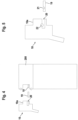
- figure 2 shows the inventive attachment of a device connection unit 10 to the light curtain 1, the device connection unit 10 itself being connected to a connection module 11, such as a plug connector.
- the Device connection 10 can also be connected to a cable 12 with an open cable end without a connection module.
- figure 2 shows an embodiment in which is provided both on the housing 2a of the transmitter unit and on the housing 2b of the receiver unit.
- a device connection unit 10 can also be provided on only one housing 2a, 2b.
- the or each device connection unit 10 forms a module as part of the sensor, in particular light curtain 1 .
- the device connection unit 10 can be fastened to the respective housing 2a, 2b by means of fastening means (not shown).
- each device connection unit 10 is connected to the connection module 11 via a cable 12 .
- connection module 11 and the cable 12 are advantageously precast or injection molded together.
- the device connection unit 10 and the cable 12 are cast or injection molded together.
- the Figures 3a, 3b show a section of the housing 2b of the light curtain 1 with a housing part 200 on its upper side.
- the device connection unit 10 (shown in Figure 3b ) to be attached.
- the device connection unit 10 can be inserted and latched with a projection 10a in a corresponding receptacle of the housing part 200 .
- a seal 13 is provided on the housing part 200 . With this seal 13, the interface between the housing part 200 and the device connection unit 10 is completely sealed.
- the seal 13 surrounds a connector panel 14, which is exposed on this end face of the housing part 200, with connector contacts 15 that can be connected to connector elements of the connector module 11, with a jumper panel 16 and with a connector for a configuration memory 17, wherein, as in Figure 3b illustrates, the configuration memory 17 can be inserted there.
- Configuration jumpers can be attached to jumper field 16.
- the configuration jumpers form electrically conductive bridges that can be used to establish an electrical connection to ground, to an operating voltage or to other contacts. Together with a pull-up, pull-down resistor or a connection to another pin, a bit can be encoded with two bit values.
- Configuration data are stored in the configuration memory 17 . If the device connection unit 10 is connected to the connection panel 14 of the housing part 200, signal distributions are carried out according to the configuration data in the configuration memory 17, i.e. input and output signals of the light curtain 1 are assigned to specific connection elements of the connection module 11. In addition, the configuration data can be used to select an operating mode for light curtain 1.
- connection panel 14 different configuration memories 17 with different configuration data can be attached to the connection panel 14 . Accordingly, different signal distributions can be set to the connection elements of the connection module 11 and/or different operating modes.
- the functionality of the device connection unit 10 can be expanded in that configuration jumpers are arranged in addition to the configuration memory 17 on the jumper field 16 .
- a configuration in a configuration memory 17 can then be selected with configuration jumpers.
- figure 4 shows a variant of the embodiment according to FIG Figures 3a and 3b .
- figure 4 shows a connection pin 18 as a connection to which a jumper bridge 19 with configuration jumpers can be attached.
- the jumper bridge 19 is inserted into a cutout 20 on the device connection unit 10 , ie the jumper bridge 19 is gripped by the device connection unit 10 .
- figure 5 shows an enlarged partial representation of the arrangement of FIG figure 4 . How out figure 5 As can be seen, the jumper bridge 19 has a notch 21 .
- Clamping device 22 may be a resilient member such as a spring, clip, elastomeric member, and the like.
- connection elements of the connection modules 11 and also operating modes of the light curtain 1 can be specified with the configuration jumper of the jumper bridge 19 in the same way as with the configuration memory 17 .
- Such a jumper 19 can, of course, also be introduced on the device side and establish the appropriate connections in the device connection unit 10 .
- Such a configuration memory 19 can, of course, also be introduced on the device side and create corresponding connections in the device connection unit 10, which then create an electrical connection to the device side via other contacts.
Abstract
Die Erfindung betrifft einen Sensor zur Erfassung von Objekten in einem Überwachungsbereich mit Sensorkomponenten und einer Auswerteeinheit (9). In der Auswerteeinheit (9) wird abhängig von Sensorsignalen der Sensorkomponenten ein Objektfeststellungssignal generiert. Der Sensor weist eine Geräteanschlusseinheit (10) auf, welches Anschlussmittel aufweist, die zum Anschluss an ein Anschlussmodul (11) ausgebildet sind. An der Geräteanschlusseinheit (10) ist ein Konfigurationsjumper und/oder ein Konfigurationsspeicher (17) anbringbar. Dadurch ist eine Signalverteilung auf Anschlusselemente des Anschlussmoduls (11) und/oder eine Betriebsart des Sensors vorgebbar.The invention relates to a sensor for detecting objects in a surveillance area with sensor components and an evaluation unit (9). An object detection signal is generated in the evaluation unit (9) as a function of sensor signals from the sensor components. The sensor has a device connection unit (10) which has connection means which are designed for connection to a connection module (11). A configuration jumper and/or a configuration memory (17) can be attached to the device connection unit (10). As a result, a signal distribution to connection elements of the connection module (11) and/or an operating mode of the sensor can be specified.
Description
Die Erfindung betrifft einen Sensor.The invention relates to a sensor.
Derartige optische Sensoren werden generell zur Erfassung von Objekten in einem Überwachungsbereich eingesetzt.Such optical sensors are generally used to detect objects in a surveillance area.
Der Sensor kann insbesondere als optischer Sensor ausgebildet sein.The sensor can be designed in particular as an optical sensor.
In der einfachsten Ausführungsform weist der optische Sensor als Sensorkomponente nur einen Lichtstrahlen emittierenden Sender und einen Lichtstrahlen empfangenden Empfänger auf. Der optische Sensor kann dabei als Lichttaster, Distanzsensor, Reflexionslichtschranke und dergleichen ausgebildet sein, wobei bei diesen Ausführungsformen der Sender und der Empfänger in einem gemeinsamen Gehäuse integriert sind. Weiterhin kann der optische Sensor auch als Lichtschranke ausgebildet sein. In diesem Fall sind der Sender und Empfänger in separaten Gehäusen untergebracht.In the simplest embodiment, the optical sensor has, as a sensor component, only a transmitter that emits light beams and a receiver that receives light beams. The optical sensor can be designed as a light sensor, distance sensor, reflection light barrier and the like, with the transmitter and the receiver being integrated in a common housing in these embodiments. Furthermore, the optical sensor can also be designed as a light barrier. In this case, the transmitter and receiver are housed in separate housings.
Generell kann der optische Sensor auch mehrere Sender und/oder Empfänger aufweisen. Ein Beispiel für einen derartigen optischen Sensor ist ein Lichtvorhang.In general, the optical sensor can also have multiple transmitters and/or receivers. An example of such an optical sensor is a light curtain.
Der Lichtvorhang umfasst typischerweise in einem ersten Gehäuse an einem Rand des Überwachungsbereichs eine Reihenanordnung von Lichtstrahlen emittierenden Sendern und in einem zweiten Gehäuse an dem gegenüberliegenden Rand des Überwachungsbereichs eine Reihenanordnung von Lichtstrahlen empfangenden Empfängern.The light curtain typically includes an array of light beam emitting transmitters in a first housing at one edge of the surveillance area and an array of light beam receiving receivers in a second housing at the opposite edge of the surveillance area.
Der optische Sensor weist als Elektronikkomponente eine Auswerteeinheit auf, in welcher in Abhängigkeit von Empfangssignalen des oder der Empfänger ein Objektfeststellungssignal generiert wird. Dieses Objektfeststellungssignal kann insbesondere als binäres Schaltsignal ausgebildet sein, dessen Schaltzustände angeben, ob sich ein Objekt im Überwachungsbereich befindet oder nicht. Das Objektfeststellungssignal kann alternativ ein analoges Signal, beispielsweise ein Distanzwert sein.As an electronic component, the optical sensor has an evaluation unit in which an object detection signal is generated as a function of received signals from the receiver or receivers. This object detection signal can in particular be in the form of a binary switching signal, the switching states of which indicate whether an object is located in the monitored area or not. The object detection signal can alternatively be an analogue signal, for example a distance value.
Zur Ausgabe des Objektfeststellungssignals und ggf. weiterer Ausgangssignale, sowie zur Eingabe von Eingangssignalen, weist der Sensor typischerweise ein Anschlussmodul, wie z.B. einen Steckverbinder, auf.The sensor typically has a connection module, such as a plug connector, for outputting the object detection signal and possibly other output signals, and for inputting input signals.
Nachteilig hierbei ist generell, dass die Anzahl von Anschlusselementen eines solchen Anschlussmoduls eng begrenzt ist. Zudem ist je nach Typ des Anschlussmoduls die Signalverteilung auf die einzelnen Anschlusselemente festgelegt. Eine Konfiguration des Anschlusselements des Anschlussmoduls ist somit nicht möglich.The general disadvantage here is that the number of connection elements of such a connection module is strictly limited. In addition, depending on the type of connection module, the signal distribution to the individual connection elements is fixed. A configuration of the connection element of the connection module is therefore not possible.
Der Erfindung liegt die Aufgabe zugrunde einen Sensor der eingangs genannten Art bereitzustellen, welcher flexibel und mit geringem konstruktivem Aufwand an unterschiedliche Anforderungen angepasst werden kann.The invention is based on the object of providing a sensor of the type mentioned at the outset, which can be adapted flexibly and with little structural effort to different requirements.
Zur Lösung dieser Aufgabe sind die Merkmale der unabhängigen Ansprüche vorgesehen. Vorteilhafte Ausführungsformen und zweckmäßige Weiterbildungen sind in den abhängigen Ansprüchen vorgesehen.To solve this problem, the features of the independent claims are provided. Advantageous embodiments and expedient developments are provided in the dependent claims.
Die Erfindung betrifft einen Sensor zur Erfassung von Objekten in einem Überwachungsbereich mit Sensorkomponenten und einer Auswerteeinheit. In der Auswerteeinheit wird abhängig von Sensorsignalen der Sensorkomponenten ein Objektfeststellungssignal generiert. Der Sensor weist eine Geräteanschlusseinheit auf, welches Anschlussmittel ausweist, die zum Anschluss an ein Anschlussmodul ausgebildet sind. An der Geräteanschlusseinheit ist ein Konfigurationsjumper und/oder ein Konfigurationsspeicher anbringbar, durch welche eine Signalverteilung auf Anschlusselemente des Anschlussmoduls und/oder eine Betriebsart des Sensors vorgebbar ist.The invention relates to a sensor for detecting objects in a surveillance area with sensor components and an evaluation unit. An object detection signal is generated in the evaluation unit as a function of sensor signals from the sensor components. The sensor has a device connection unit, which has connection means that are designed for connection to a connection module. On the device connection unit is a Configuration jumpers and/or a configuration memory can be attached, through which a signal distribution to connection elements of the connection module and/or an operating mode of the sensor can be specified.
Die Erfindung betrifft weiterhin ein entsprechendes Verfahren.The invention further relates to a corresponding method.
Der erfindungsgemäße Sensor dient zur Erfassung von Objekten in einem Überwachungsbereich. Hierzu weist der Sensor Sensorkomponenten und eine Auswerteeinheit auf, wobei in der Auswerteeinheit abhängig von Sensorsignalen ein Objektfeststellungssignal generiert wird.The sensor according to the invention is used to detect objects in a surveillance area. For this purpose, the sensor has sensor components and an evaluation unit, with an object detection signal being generated in the evaluation unit as a function of sensor signals.
Der Sensor weist in an sich bekannter Weise ein Anschlussmodul, wie z.B. einen Steckverbinder auf, der einerseits nur zur Stromversorgung des Sensors dient und andererseits Anschlusselemente aufweist, über welche Eingabesignale in den Sensor eingegeben und Ausgangssignale vom Sensor ausgegeben werden können.In a manner known per se, the sensor has a connection module, such as a plug connector, which on the one hand only serves to supply power to the sensor and on the other hand has connection elements via which input signals can be input into the sensor and output signals can be output from the sensor.
Erfindungsgemäß ist diese Schnittstelle konfigurierbar, so dass die Funktion des Sensors selbst durch eine Betriebsartenwahl vorgegeben werden kann. Alternativ oder zusätzlich kann die Signalverteilung auf die Anschlusselemente je nach Anwendungsfall angepasst werden. Dadurch kann insbesondere eine Anschlusskompatibilität zu unterschiedlichen externen Einheiten, an welche der Sensor mit dem Anschlussmodul angeschlossen werden kann, hergestellt werden.According to the invention, this interface can be configured so that the function of the sensor itself can be specified by selecting an operating mode. Alternatively or additionally, the signal distribution to the connection elements can be adjusted depending on the application. In this way, in particular, connection compatibility with different external units to which the sensor with the connection module can be connected can be established.
Diese Konfigurierbarkeit wird dadurch erreicht, dass der Sensor eine Geräteanschlusseinheit mit einem Konfigurationsspeicher und/oder mit Konfigurationsjumpern aufweist.This configurability is achieved in that the sensor has a device connection unit with a configuration memory and/or with configuration jumpers.
Mit den Konfigurationsjumpern kann hardwaremäßig eine bestimmte Konfiguration vorgegeben wird. Mit dem Konfigurationsspeicher kann durch dort gespeicherte Konfigurationsdaten eine Konfiguration vorgegeben werden.With the configuration jumpers, a specific hardware configuration can be specified. With the configuration memory, a configuration can be specified by configuration data stored there.
Je nach Ausbildung der Konfigurationsjumper und/oder des Konfigurationsspeichers wird eine spezifische Signalverteilung für die Anschlusselemente des Anschlussmoduls und/oder eine Betriebsart des Sensors eingestellt.Depending on the design of the configuration jumpers and/or the configuration memory, a specific signal distribution for the connection elements of the connection module and/or an operating mode of the sensor is set.
Im einfachsten Fall können unterschiedliche Konfigurationsjumper bzw. Konfigurationsspeicher eingesetzt werden, um unterschiedliche Konfigurationen des Sensors vorzugeben.In the simplest case, different configuration jumpers or configuration memories can be used in order to specify different configurations of the sensor.
Gemäß einer ersten vorteilhaften Weiterbildung ist der oder jeder Konfigurationsspeicher über eine Schnittstelle parametrierbar.According to a first advantageous development, the or each configuration memory can be parameterized via an interface.
Der Konfigurationsspeicher ist dann ein Speichermodul mit einer eigenen Schnittstelle, an welche ein externes Gerät angeschlossen werden kann, um Konfigurationsdaten in den Konfigurationsspeicher einzulesen. Das externe Gerät kann generell von einer Rechnereinheit gebildet sein. Durch Einlesen unterschiedlicher Konfigurationsdaten können unterschiedliche Konfigurationen des Sensors vorgegeben werden.The configuration memory is then a memory module with its own interface to which an external device can be connected in order to read configuration data into the configuration memory. The external device can generally be formed by a computer unit. Different configurations of the sensor can be specified by reading in different configuration data.
Gemäß einer zweiten vorteilhaften Weiterbildung sind an der Geräteanschlusseinheit sowohl ein Konfigurationsspeicher als auch Konfigurationsjumper vorgesehen. Dann ist mit Konfigurationsjumpern eine Konfiguration in einem Konfigurationsspeicher auswählbar.According to a second advantageous development, both a configuration memory and a configuration jumper are provided on the device connection unit. A configuration in a configuration memory can then be selected with configuration jumpers.
Durch unterschiedliche Einstellungen von Konfigurationsjumpern können somit unterschiedliche Konfigurationen, die durch im Konfigurationsspeicher abgespeicherte Konfigurationsdaten vorgegeben sind, eingestellt werden.Different configurations, which are specified by configuration data stored in the configuration memory, can thus be set by different settings of configuration jumpers.
Ein Konfigurationsjumper bildet generell eine leitende Brücke, über welche eine Masse-Verbindung hergestellt werden kann. Zusammen mit einem Pull-up-Widerstand wird mit dem Konfigurationsjumper eine einem Bit entsprechende Information zur Verfügung gestellt. Mit N Konfigurationsjumpern können somit 2N Adressen generiert werden, die zur Auswahl unterschiedlicher Konfigurationen, d.h. Betriebsarten oder Signalverteilungen für das Anschlussmodul herangezogen werden können.A configuration jumper generally forms a conductive bridge over which a ground connection can be established. Together with a pull-up resistor, information corresponding to one bit is made available with the configuration jumper. With N configuration jumpers, 2 N addresses can thus be generated, which can be used to select different Configurations, ie operating modes or signal distributions for the connection module can be used.
Gemäß einer vorteilhaften konstruktiven Ausgestaltung weist der Sensor wenigstens ein Gehäuse auf, wobei die Geräteanschlusseinheit an einem Gehäuseteil des Gehäuses befestigbar ist.According to an advantageous structural configuration, the sensor has at least one housing, with the device connection unit being able to be fastened to a housing part of the housing.
Dabei ist zwischen dem Gehäuseteil und der Geräteanschlusseinheit eine Dichtung vorgesehen.A seal is provided between the housing part and the device connection unit.
Die Nahtstelle zwischen Geräteanschlusseinheit und dem Gehäuse des Sensors ist damit vollständig abgedichtet.The interface between the device connection unit and the housing of the sensor is thus completely sealed.
Gemäß einer ersten Variante sind der Konfigurationsspeicher und/oder die Konfigurationsjumper am Gehäuseteil steckbar.According to a first variant, the configuration memory and/or the configuration jumpers can be plugged into the housing part.
Durch die Steckverbindung bilden der Konfigurationsspeicher und/oder die Konfigurationsjumper eine Baueinheit mit dem Gehäuse, auf welche dann die Geräteanschlusseinheit geführt wird, so das dann bei am Gehäuseteil fixierter Geräteanschlusseinheit der Konfigurationsspeicher und/oder die Konfigurationsjumper von der Geräteanschlusseinheit gegriffen sind.The plug-in connection means that the configuration memory and/or the configuration jumpers form a structural unit with the housing, onto which the device connection unit is then routed, so that when the device connection unit is fixed to the housing part, the configuration memory and/or the configuration jumpers are gripped by the device connection unit.
Gemäß einer zweiten Variante sind der Konfigurationsspeicher und/oder die Konfigurationsjumper an der Geräteanschlusseinheit steckbar.According to a second variant, the configuration memory and/or the configuration jumpers can be plugged into the device connection unit.
In diesem Fall bilden durch die Steckverbindung der Konfigurationsspeicher und/oder die Konfigurationsjumper eine Baueinheit mit der Geräteanschlusseinheit, die dann auf das Gehäuseteil aufgesetzt wird, so dass dann bei am Gehäuseteil fixierter Geräteanschlusseinheit des Konfigurationsspeichers und/oder die Konfigurationsjumper von dem Gehäuseteil gegriffen sind.In this case, the plug-in connection means that the configuration memory and/or the configuration jumpers form a structural unit with the device connection unit, which is then placed on the housing part, so that when the device connection unit is fixed to the housing part, the configuration memory and/or the configuration jumpers are gripped by the housing part.
Generell ist es auch möglich, dass in der Geräteanschlusseinheit fest verdrahtete Konfigurationsjumper vorgesehen sind.In general, it is also possible for permanently wired configuration jumpers to be provided in the device connection unit.
Das insbesondere als Steckverbinder ausgebildete Anschlussmodul kann über ein Kabel mit der Geräteanschlusseinheit verbunden sein.The connection module, which is designed in particular as a plug connector, can be connected to the device connection unit via a cable.
Dann können vorteilhaft das Anschlussmodul und das Kabel zusammen vorgossen oder gespritzt sein.The connection module and the cable can then advantageously be precast or injection molded together.
Alternativ können die Geräteanschlusseinheit und das Kabel zusammen vergossen oder gespritzt sein.Alternatively, the device connection unit and the cable can be potted or injection molded together.
Der erfindungsgemäße Sensor kann insbesondere als Sicherheitssensor ausgebildet sein, das heißt der Sensor weist dann einen fehlersicheren Aufbau auf, so dass er in sicherheitsrelevanten Applikationen, zum Beispiel im Bereich des Personenschutzes eingesetzt werden kann.The sensor according to the invention can in particular be designed as a safety sensor, that is to say the sensor then has a fail-safe structure, so that it can be used in safety-relevant applications, for example in the field of personal protection.
Ein fehlersicherer Aufbau wird insbesondere durch einen redundanten, vorteilhaft zweikanaligen Aufbau der Auswerteeinheit, beispielsweise in Form zweier sich zyklisch gegenseitig überwachenden Rechnereinheiten realisiert.A fail-safe design is implemented in particular by a redundant, advantageously two-channel design of the evaluation unit, for example in the form of two computer units which cyclically monitor one another.
Wird mit den Rechnereinheiten der Auswerteeinheit ein Fehler realisiert, geht der Sicherheitssensor in den sicheren Zustand, beispielsweise dadurch, dass dieser ein Objektfeststellungssignal generiert, mit dem eine überwachte, gefahrbringende Maschine abgeschaltet wird.If an error occurs with the computer units of the evaluation unit, the safety sensor goes into the safe state, for example by generating an object detection signal with which a monitored, dangerous machine is switched off.
Der erfindungsgemäße Sensor kann prinzipiell ein Radarsensor oder ein Ultraschallsensor sein. Besonders vorteilhaft ist der Sensor ein optischer Sensor.In principle, the sensor according to the invention can be a radar sensor or an ultrasonic sensor. The sensor is particularly advantageously an optical sensor.
Der optische Sensor kann insbesondere als Flächendistanzsensor, d.h. als scannender Distanzsensor oder als Lichtvorhang ausgebildet sein.The optical sensor can in particular be designed as a surface distance sensor, i.e. as a scanning distance sensor or as a light curtain.
Die Erfindung wird im Folgenden anhand der Zeichnungen erläutert. Es zeigen:
- Figur 1:
- Ausführungsbeispiel des erfindungsgemäßen Sensors in Form eines Lichtvorhangs.
- Figur 2:
- Schematische Darstellung des Lichtvorhangs gemäß
Figur 1 mit Geräteanschlusseinheit und zugeordnetem Anschlussmodul. - Figur 3a:
- Einzeldarstellung eines Gehäuseteils des Lichtvorhangs mit einer zugeordneten Geräteanschlusseinheit.
- Figur 3b:
- Draufsicht auf das Gehäuseteil gemäß
Figur 3a . - Figur 4:
- Variante der Ausführungsform gemäß
Figur 3a . - Figur 5:
- Spezifische konstruktive Ausgestaltung der Geräteanschlusseinheit gemäß
Figur 4
- Figure 1:
- Embodiment of the sensor according to the invention in the form of a light curtain.
- Figure 2:
- Schematic representation of the light curtain according to
figure 1 with device connection unit and assigned connection module. - Figure 3a:
- Individual representation of a housing part of the light curtain with an associated device connection unit.
- Figure 3b:
- Top view of the housing part according to
Figure 3a . - Figure 4:
- Variant according to the embodiment
Figure 3a . - Figure 5:
- Specific structural design of the device connection unit according to
figure 4 .
Der Lichtvorhang 1 weist eine Sendereinheit mit einem Gehäuse 2a mit einer Reihenanordnung von Lichtstrahlen 3 emittierenden Sendern 4 als erste Sensorkomponente und diesen zugeordneten Optikelemente bildenden Sendeoptiken 5 auf. Weiterhin weist der Lichtvorhang 1 eine Empfängereinheit mit einem zweiten Gehäuse 2b mit einer Reihenanordnung von Lichtstrahlen 3 empfangenden Empfängern 6 als zweite Sensorkomponente auf, welche jeweils ein Optikelement in Form einer Empfangsoptik 7 vorgeordnet ist.The
Die Gehäuse 2a, 2b sind an gegenüberliegenden Rändern des Überwachungsbereichs so angeordnet, dass jeweils ein Empfänger 6 einem Sender 4 gegenüberliegend angeordnet ist und mit diesem ein Sender-Empfänger-Paar bildet, wobei die Lichtstrahlen 3 des Senders 4 eine Strahlachse bilden. Im vorliegenden Fall sind acht Strahlachsen vorgesehen. Natürlich kann der Lichtvorhang 1 auch eine andere Zahl von Strahlachsen aufweisen.The
Alternativ kann der Lichtvorhang 1 auch als Reflexions-Lichtvorhang 1 ausgebildet sein. Dann sind alle Sender 4 und Empfänger 6 in einem Gehäuse 2a oder 2b angeordnet, welche an einem Rand des Überwachungsbereichs angeordnet ist. Am anderen Ende befindet sich ein Reflektor. Bei freiem Überwachungsbereich werden die Lichtstrahlen 3 der Sender 4 über den Reflektor zurück zum jeweils zugeordneten Empfänger 6 geführt.Alternatively, the
Die Sender 4 werden von einer Sendersteuerung 8 gesteuert. Den Empfängern 6 ist eine Auswerteeinheit 9 zugeordnet. Dabei werden die Strahlachsen zyklisch einzeln nacheinander aktiviert. Die Auswerteeinheit 9 steuert die Empfänger 6 an und wertet deren Empfangssignale zur Generierung eines Objektfeststellungssignals in Form eines binären Schaltsignals aus, dessen Schaltzustände angeben, ob sich ein Objekt im Überwachungsbereich befindet oder nicht. Bei freiem Überwachungsbereich gelangen die Lichtstrahlen 3 der Strahlachsen ungehindert zum Empfänger 6 der jeweiligen Strahlachse. Bei einem Objekteingriff wird wenigstens eine Strahlachse unterbrochen. Die Sendersteuerung 8 und/oder Auswerteeinheit 9 kann einen mehrkanaligen Aufbau aufweisen, falls der Lichtvorhang 1 einen Sicherheitssensor bildet. Insbesondere kann die Sendersteuerung 8 und/oder Auswerteeinheit 9 aus zwei sich zyklisch überwachenden Rechnereinheiten bestehen.The
Mit dem als Sicherheitssensor ausgebildeten Lichtvorhang 1 wird beispielsweise ein Gefahrenbereich an einer Maschine überwacht. Nur bei freiem Überwachungsbereich wird der Betrieb der Maschine freigegeben. Wird in der Sendersteuerung 8 und Auswerteeinheit 9 ein Fehler aufgedeckt, wird ein Schaltsignal im Lichtvorhang 1 derart generiert, dass die Maschine abgeschaltet wird, das heißt es erfolgt ein Übergang in einen sicheren Zustand.A danger zone on a machine, for example, is monitored with the
Die oder jede Geräteanschlusseinheit 10 bildet ein Modul als Bestandteil des Sensors, insbesondere Lichtvorhangs 1, aus. Die Geräteanschlusseinheit 10 kann mittels nicht dargestellten Befestigungsmitteln am jeweiligen Gehäuse 2a, 2b befestigt werden.The or each
Im vorliegenden Fall ist jede Geräteanschlusseinheit 10 über ein Kabel 12 mit dem Anschlussmodul 11 verbunden.In the present case, each
Vorteilhaft ist das Anschlussmodul 11 und das Kabel 12 zusammen vorgossen oder gespritzt.The
Alternativ ist die Geräteanschlusseinheit 10 und das Kabel 12 zusammen vergossen oder gespritzt.Alternatively, the
Die
An dem Gehäuseteil 200 ist eine Dichtung 13 vorgesehen. Mit dieser Dichtung 13 wird die Nahtstelle zwischen dem Gehäuseteil 200 und der Geräteanschlusseinheit 10 vollständig abgedichtet.A
Die Dichtung 13 umgibt ein an dieser Stirnseite des Gehäuseteils 200 freiliegendes Anschlussfeld 14 mit Anschlusskontakten 15, die mit Anschlusselementen des Anschlussmoduls 11 verbindbar sind, mit einem Jumperfeld 16 und mit einem Anschluss für einen Konfigurationsspeicher 17, wobei, wie in
Im Konfigurationsspeicher 17 sind Konfigurationsdaten abgespeichert. Ist die Geräteanschlusseinheit 10 mit dem Anschlussfeld 14 des Gehäuseteils 200 verbunden, werden entsprechend den Konfigurationsdaten im Konfigurationsspeicher 17 Signalverteilungen vorgenommen, d.h. Ein- und Ausgangssignale des Lichtvorhangs 1 bestimmten Anschlusselementen des Anschlussmoduls 11 zugeordnet. Zudem kann mit den Konfigurationsdaten eine Betriebsartenwahl für den Lichtvorhang 1 vorgenommen werden.Configuration data are stored in the
An dem Anschlussfeld 14 können prinzipiell unterschiedliche Konfigurationsspeicher 17 mit unterschiedlichen Konfigurationsdaten angebracht werden. Dementsprechend können unterschiedliche Signalverteilungen auf die Anschlusselemente des Anschlussmoduls 11 und/oder verschiedene Betriebsarten eingestellt werden.In principle,
Weiterhin ist es möglich, dass der oder jeder Konfigurationsspeicher 17 über eine Schnittstelle parametrierbar ist.It is also possible for the or each
Die Funktionalität der Geräteanschlusseinheit 10 kann dadurch erweitert sein, dass zusätzlich zum Konfigurationsspeicher 17 am Jumperfeld 16 Konfigurationsjumper angeordnet sind.The functionality of the
Dann kann mit Konfigurationsjumpern eine Konfiguration in einem Konfigurationsspeicher 17 ausgewählt werden.A configuration in a
Wird die Jumperbrücke 19 in die Aussparung 20 der Geräteanschlusseinheit 10 eingeführt, ist eine Klemmeinrichtung 22 in die Kerbe 21 eingeführt, wodurch die Jumperbrücke 19 an der Geräteanschlusseinheit 10 fixiert ist. Die Klemmeinrichtung 22 kann ein elastisches Element z.B. eine Feder, eine Klammer, ein Elastomerelement und dergleichen sein.If the
Mit dem Konfigurationsjumper der Jumperbrücke 19 können auf gleiche Weise wie mit dem Konfigurationsspeicher 17 Signalverteilungen für Anschlusselemente der Anschlussmodule 11 und auch Betriebsarten des Lichtvorhang 1 vorgegeben sein.Signal distributions for connection elements of the
Eine solche Jumperbrücke 19 kann, natürlich auch auf der Geräteseite eingeführt sein und die entsprechenden Verbindungen in der Geräteanschlusseinheit 10 herstellen.Such a
Bei den Anordnungen der
Ein solcher Konfigurationsspeicher 19 kann natürlich auch auf der Geräteseite eingeführt sein und entsprechende Verbindungen in der Geräteanschlusseinheit 10 herstellen, die dann über andere Kontakte eine elektrische Verbindung zur Geräteseite herstellen.Such a
- (1)(1)
- Lichtvorhanglight curtain
- (2a)(2a)
- GehäuseHousing
- (2b)(2 B)
- GehäuseHousing
- (3)(3)
- Lichtstrahlenrays of light
- (4)(4)
- SenderChannel
- (5)(5)
- Sendeoptiktransmission optics
- (6)(6)
- EmpfängerRecipient
- (7)(7)
- Empfangsoptikreceiving optics
- (8)(8th)
- Sendersteuerungtransmitter control
- (9)(9)
- Auswerteeinheitevaluation unit
- (10)(10)
- Geräteschlusseinheitdevice terminal unit
- (10a)(10a)
- Vorsprunghead Start
- (11)(11)
- Anschlussmodulconnection module
- (12)(12)
- KabelCable
- (13)(13)
- Dichtungpoetry
- (14)(14)
- Anschlussfeldconnector panel
- (15)(15)
- Anschlusskontaktconnection contact
- (16)(16)
- Jumperfeldjumper field
- (17)(17)
- Konfigurationsspeicherconfiguration storage
- (18)(18)
- Anschlusspinconnection pin
- (19)(19)
- Jumperbrückejumper bridge
- (20)(20)
- Aussparungrecess
- (21)(21)
- Kerbescore
- (22)(22)
- Klemmeinrichtungclamping device
- (200)(200)
- Gehäuseteilhousing part
Claims (20)
Priority Applications (3)
| Application Number | Priority Date | Filing Date | Title |
|---|---|---|---|
| EP22157858.6A EP4231060A1 (en) | 2022-02-22 | 2022-02-22 | Sensor |
| US18/099,922 US20230266495A1 (en) | 2022-02-22 | 2023-01-21 | Sensor |
| CN202310149918.1A CN116643325A (en) | 2022-02-22 | 2023-02-22 | Sensor for detecting a position of a body |
Applications Claiming Priority (1)
| Application Number | Priority Date | Filing Date | Title |
|---|---|---|---|
| EP22157858.6A EP4231060A1 (en) | 2022-02-22 | 2022-02-22 | Sensor |
Publications (1)
| Publication Number | Publication Date |
|---|---|
| EP4231060A1 true EP4231060A1 (en) | 2023-08-23 |
Family
ID=80446165
Family Applications (1)
| Application Number | Title | Priority Date | Filing Date |
|---|---|---|---|
| EP22157858.6A Pending EP4231060A1 (en) | 2022-02-22 | 2022-02-22 | Sensor |
Country Status (3)
| Country | Link |
|---|---|
| US (1) | US20230266495A1 (en) |
| EP (1) | EP4231060A1 (en) |
| CN (1) | CN116643325A (en) |
Citations (3)
| Publication number | Priority date | Publication date | Assignee | Title |
|---|---|---|---|---|
| EP2050997A1 (en) * | 2007-09-19 | 2009-04-22 | Sick Ag | Safety light grid |
| US20170146687A1 (en) * | 2015-11-20 | 2017-05-25 | Banner Engineering Corp. | User selectable remote programming for cascade-connected light curtains |
| US20180025614A1 (en) * | 2016-07-20 | 2018-01-25 | Banner Engineering Corp. | Light curtain protection system featuring a passive optical module |
-
2022
- 2022-02-22 EP EP22157858.6A patent/EP4231060A1/en active Pending
-
2023
- 2023-01-21 US US18/099,922 patent/US20230266495A1/en active Pending
- 2023-02-22 CN CN202310149918.1A patent/CN116643325A/en active Pending
Patent Citations (3)
| Publication number | Priority date | Publication date | Assignee | Title |
|---|---|---|---|---|
| EP2050997A1 (en) * | 2007-09-19 | 2009-04-22 | Sick Ag | Safety light grid |
| US20170146687A1 (en) * | 2015-11-20 | 2017-05-25 | Banner Engineering Corp. | User selectable remote programming for cascade-connected light curtains |
| US20180025614A1 (en) * | 2016-07-20 | 2018-01-25 | Banner Engineering Corp. | Light curtain protection system featuring a passive optical module |
Also Published As
| Publication number | Publication date |
|---|---|
| CN116643325A (en) | 2023-08-25 |
| US20230266495A1 (en) | 2023-08-24 |
Similar Documents
| Publication | Publication Date | Title |
|---|---|---|
| EP0883527B1 (en) | Control system for a restraining device, particularly in a motor vehicle | |
| DE3520003C2 (en) | ||
| EP1816487A1 (en) | Light barrier | |
| DE102007020882B4 (en) | Device for checking the attachment of a printed circuit board to a carrier | |
| EP2843447B1 (en) | Light grid | |
| EP1873915B1 (en) | Secure input circuit with single channel peripheral connection for the input of a bus participant | |
| EP1748299B1 (en) | Electronic circuit, system with an electronic circuit and method to test an electronic circuit | |
| DE4307794A1 (en) | Device for monitoring symmetrical two-wire bus lines and bus interfaces | |
| DE10251350B4 (en) | Optical sensor | |
| EP4231060A1 (en) | Sensor | |
| EP1776518B1 (en) | Sensor for measuring the position of an actuator | |
| EP1347388B1 (en) | Coupling device for connecting devices to a bus system | |
| DE10345819B4 (en) | Electronic, preferably non-contact switching device | |
| DE102013111888B4 (en) | Safety device for multi-channel processing of an analog input signal | |
| EP1094301B1 (en) | Optical sensor | |
| EP1895329A2 (en) | Device for recording objects in a surveillance range | |
| EP2639603A2 (en) | Sensor assembly | |
| DE102006048146B4 (en) | Sensor arrangement, use of a sensor arrangement and method for monitoring the safety of a machine | |
| DE10155583B4 (en) | circuitry | |
| DE202006020112U1 (en) | Device with a sensor and an associated memory unit | |
| DE10155582B4 (en) | circuitry | |
| DE19741945C2 (en) | magnetic sensor | |
| EP4080251B1 (en) | Sensor and method for operating same | |
| EP1522876A2 (en) | Optical sensor | |
| EP0670033B1 (en) | Circuitry for processing analogical current and voltage signals |
Legal Events
| Date | Code | Title | Description |
|---|---|---|---|
| PUAI | Public reference made under article 153(3) epc to a published international application that has entered the european phase |
Free format text: ORIGINAL CODE: 0009012 |
|
| STAA | Information on the status of an ep patent application or granted ep patent |
Free format text: STATUS: REQUEST FOR EXAMINATION WAS MADE |
|
| 17P | Request for examination filed |
Effective date: 20220826 |
|
| AK | Designated contracting states |
Kind code of ref document: A1 Designated state(s): AL AT BE BG CH CY CZ DE DK EE ES FI FR GB GR HR HU IE IS IT LI LT LU LV MC MK MT NL NO PL PT RO RS SE SI SK SM TR |