EP4230923A1 - Air barrier apparatus for automatically opening sliding doors - Google Patents
Air barrier apparatus for automatically opening sliding doors Download PDFInfo
- Publication number
- EP4230923A1 EP4230923A1 EP23157193.6A EP23157193A EP4230923A1 EP 4230923 A1 EP4230923 A1 EP 4230923A1 EP 23157193 A EP23157193 A EP 23157193A EP 4230923 A1 EP4230923 A1 EP 4230923A1
- Authority
- EP
- European Patent Office
- Prior art keywords
- air
- intake
- infrared device
- flow
- casing
- Prior art date
- Legal status (The legal status is an assumption and is not a legal conclusion. Google has not performed a legal analysis and makes no representation as to the accuracy of the status listed.)
- Granted
Links
Images

Classifications
-
- F—MECHANICAL ENGINEERING; LIGHTING; HEATING; WEAPONS; BLASTING
- F24—HEATING; RANGES; VENTILATING
- F24F—AIR-CONDITIONING; AIR-HUMIDIFICATION; VENTILATION; USE OF AIR CURRENTS FOR SCREENING
- F24F9/00—Use of air currents for screening, e.g. air curtains
-
- F—MECHANICAL ENGINEERING; LIGHTING; HEATING; WEAPONS; BLASTING
- F24—HEATING; RANGES; VENTILATING
- F24F—AIR-CONDITIONING; AIR-HUMIDIFICATION; VENTILATION; USE OF AIR CURRENTS FOR SCREENING
- F24F9/00—Use of air currents for screening, e.g. air curtains
- F24F2009/005—Use of air currents for screening, e.g. air curtains combined with a door
Definitions
- air barriers constituted by a regulated flow of air forming a vertical barrier, also called “thermal curtain”, invisible and descending, which acts as a contrast to the mass of air, which, depending on the thermo-hygrometric conditions of the environment, naturally enters from the outside or evacuates from the inside towards the outside.
- the air barrier is made by means of a ventilation apparatus enclosed in a casing, equipped with air intake vents and vents placed below for the exit of the vertical flow of air that makes the aforementioned air barrier.
- the "air barrier" is made with a flow of slightly heated air.
- the air barriers equipped with electrical resistors are the most common for ease of installation, but they need models with powerful resistors to be able to heat the air sufficiently and therefore require a considerable and expensive energy consumption expressed in kWh.
- the infrared lamp is positioned upstream of the intake fan and engages a portion and the total flow rate of the flow of air to be heated.
- an air barrier apparatus adapted to be positioned above a door "P", which is usually automatic, comprises a casing 2 equipped with at least one air intake vent 3 and, at least at its own lower part, with vents 4 for the exit of ventilated air adapted to form the desired vertical air barrier "H".
- the air is sucked into said casing by at least one intake fan 5 inside the casing 2 which generates a flow of air from the intake vents 3 to the exit vents 4.
- the infrared device 10 is positioned upstream of the intake fan 5 and engages at least a portion of the flow of air to be heated.
- the intake fan 5 can advantageously suck air also from any intake vents 3 without heating means, as visible in Fig. 1 .
- the infrared device 10 is positioned in the lower part of the casing 2, near at least one intake vent 3, so that the heat waves K, radiated downwards through said vent 3, are adapted to hit, with a localised heating, a person transiting under the air barrier apparatus 1.
- the heat waves K may pass through the openings of the intake vent 3 which are necessary to allow air in.
- the innovative feature of the invention consists in the fact of equipping the air barrier apparatus 1 with an infrared device 10 capable of simultaneously heating by irradiation at least a part of the flow of air entering the intake fan 5 and a possible user who passes under said apparatus, so as to increase the overall well-being of the same, who will not perceive cold sensations.
- the heated part of the flow of air can advantageously mix also with another part, indicated with the reference “B”, of air being sucked, thus heating it so that the exiting ventilated and heated air, indicated with the reference “C”, provides a vertical air barrier "H" at the required temperature.
- the infrared device 10 heats the total flow rate of the area being sucked.
- a reflective panel 6 positioned above the infrared device 10 may advantageously be provided to reflect downwards the rays emitted by the device 10, which would otherwise heat the internal components of the apparatus 1.
- an air barrier apparatus 1 in which at least one air deflector 8 is provided, placed above at least one intake vent 3, so as to direct the flow of air coming from said intake vent 3 towards the intake fan 5.
- This embodiment allows to avoid dispersion of the heated air, increasing the efficiency of the apparatus 1.
Landscapes
- Engineering & Computer Science (AREA)
- Chemical & Material Sciences (AREA)
- Combustion & Propulsion (AREA)
- Mechanical Engineering (AREA)
- General Engineering & Computer Science (AREA)
- Specific Sealing Or Ventilating Devices For Doors And Windows (AREA)
Abstract
Description
- The present invention concerns an air barrier apparatus for automatically opening sliding doors, according to the general part of
claim 1. - As is well known, in spaces frequented by a large number of people, such as shopping malls, railway stations, airports, hospitals, banks and other places with the same specificities, the continuous opening and closing of doors generates a series of problems, in particular:
- the formation of annoying air streams at the opening area of the door;
- a thermo-hygrometric decompensation of the internal environment with consequent loss of pressure of the air conditioning system inside the room;
- infiltrations of dust and other pollutants from outside.
- These problems are solved with the use of so-called "air barriers", constituted by a regulated flow of air forming a vertical barrier, also called "thermal curtain", invisible and descending, which acts as a contrast to the mass of air, which, depending on the thermo-hygrometric conditions of the environment, naturally enters from the outside or evacuates from the inside towards the outside.
- Constructively, the air barrier is made by means of a ventilation apparatus enclosed in a casing, equipped with air intake vents and vents placed below for the exit of the vertical flow of air that makes the aforementioned air barrier.
- This involves the fact that a person, at the moment of trespassing the door, is hit by a blow of air coming from above which, even if the air is at room temperature, due to the fact of constituting a flow at high speed, makes the person perceive the annoying sensation of the presence of "cold air".
- In order to eliminate this negative sensation, the "air barrier" is made with a flow of slightly heated air.
- At the current state of the art, the air forming the barrier or hot "air blade" is heated by means of two systems:
- with the use of electrical resistors;
- with the use of hot water batteries.
- Operationally, both systems show drawbacks.
- Specifically, the air barriers equipped with electrical resistors are the most common for ease of installation, but they need models with powerful resistors to be able to heat the air sufficiently and therefore require a considerable and expensive energy consumption expressed in kWh.
- On the other hand, the air barriers equipped with hot water batteries, although with considerably reduced operating costs compared to the electrical system, require considerable installation and maintenance costs.
- Air barriers comprising therein infrared devices such as, for example, the one described in
WO 89/01592 A1 US 3211077 describes an air barrier apparatus in which infrared heating devices are present which, however, also in this case are not placed directly inside the flow of air of the barrier which they heat at a distance. It is clear that, precisely because of this distance, the heating will be very mild and the air of the barrier will be relatively warm. - Aim of the present invention is to realize an air barrier apparatus for automatically opening sliding doors that maximizes the efficacy of the use of infrared technology, avoiding the problems known in the art.
- This aim is achieved by providing that, in order to heat the air and to directly heat a user who crosses the barrier, an infrared device is used, commonly known as an "infrared lamp", where the heat produced is transmitted by irradiation to the hit bodies. In practice, the use of infrared lamps, compared to other heating means, allows:
- to have a greater heating efficacy with the same power absorbed;
- a rapid reaching of the operating temperature and an equally rapid shutdown, so it is possible to operate the lamp only for the time strictly necessary to open/close the door whereas, on the other hand, the electrical resistors or hot water batteries, due to their "thermal hysteresis", must always be kept in operation, with consequent considerable energy costs.
- Constructively, the infrared lamp is positioned upstream of the intake fan and engages a portion and the total flow rate of the flow of air to be heated.
- Advantageously, the infrared lamp is placed in the lower part of the casing so that, thanks to the localised heating of the lamp provided with the infrared rays, it is possible to direct its heat waves downwards, which are added to the hot air barrier, thus helping to increase the well-being of the person trespassing the door.
- The invention will be better defined with the description of a possible embodiment thereof, made by way of non-limiting example only, through the attached drawing tables, where:
-
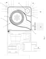
fig. 1 shows a sectional view of a casing containing the air barrier apparatus equipped with an infrared heating lamp; -
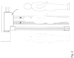
fig. 2 shows an air barrier apparatus in the operating step; -
fig. 3 shows a particular embodiment of an air barrier apparatus equipped with a particular housing for the infrared device; -
fig. 4 shows a further embodiment of an air barrier apparatus equipped with a deflector for directing the flow of air towards the intake fan. - As a rule, an air barrier apparatus, indicated with
reference 1, adapted to be positioned above a door "P", which is usually automatic, comprises acasing 2 equipped with at least oneair intake vent 3 and, at least at its own lower part, withvents 4 for the exit of ventilated air adapted to form the desired vertical air barrier "H". The air is sucked into said casing by at least oneintake fan 5 inside thecasing 2 which generates a flow of air from theintake vents 3 to theexit vents 4. - By at least one of the
intake vents 3 at least oneinfrared device 10 is present, better known as an "infrared lamp", capable of eliminating the negative sensation of the presence of "cold air", which a person would perceive when trespassing the door, if he were hit by a flow of air at high speed without any preheating. - The
infrared device 10 is positioned upstream of theintake fan 5 and engages at least a portion of the flow of air to be heated. Theintake fan 5 can advantageously suck air also from anyintake vents 3 without heating means, as visible inFig. 1 . - To make the best use of the technology and obtain the maximum efficiency, it is provided that the
infrared device 10 is positioned in the lower part of thecasing 2, near at least oneintake vent 3, so that the heat waves K, radiated downwards through saidvent 3, are adapted to hit, with a localised heating, a person transiting under theair barrier apparatus 1. The heat waves K may pass through the openings of theintake vent 3 which are necessary to allow air in. - Therefore, as visible in
fig. 1 , the innovative feature of the invention consists in the fact of equipping theair barrier apparatus 1 with aninfrared device 10 capable of simultaneously heating by irradiation at least a part of the flow of air entering theintake fan 5 and a possible user who passes under said apparatus, so as to increase the overall well-being of the same, who will not perceive cold sensations. - The heated part of the flow of air, indicated with the reference "A" in
Fig. 1 , can advantageously mix also with another part, indicated with the reference "B", of air being sucked, thus heating it so that the exiting ventilated and heated air, indicated with the reference "C", provides a vertical air barrier "H" at the required temperature. - It is also possible to provide that the
infrared device 10 heats the total flow rate of the area being sucked. -
Fig. 3 shows a particular embodiment of an apparatus according to the invention in which at least oneintake vent 3, near which there is aninfrared device 10, has a substantially circular cross-section open on its lower and upper part, so as to allow the intake of the air by means of theintake fan 5. - Advantageously in this case, the
infrared device 10 can be more exposed to the external environment of thecasing 2 than traditional grid intake vents, as it is positioned inside the perimeter of theintake vent 3 and this fact improves the efficacy of the direct irradiation operation of the user. - In addition, a
reflective panel 6 positioned above theinfrared device 10 may advantageously be provided to reflect downwards the rays emitted by thedevice 10, which would otherwise heat the internal components of theapparatus 1. - Said
reflective panel 6 comprises at least onehole 7 to allow the passage of the air to be sucked in. - In the further embodiment illustrated in
Fig. 4 anair barrier apparatus 1 is shown in which at least oneair deflector 8 is provided, placed above at least oneintake vent 3, so as to direct the flow of air coming from saidintake vent 3 towards theintake fan 5. - This embodiment allows to avoid dispersion of the heated air, increasing the efficiency of the
apparatus 1. - An air barrier apparatus of the type described in the invention is usually configured to be switched on only when a user is passing so as not to waste electricity unnecessarily for its operation.
- A control unit (not illustrated) may be provided adapted to receive data concerning the passage of a user under the
apparatus 1, in order to operate it accordingly. Advantageously, in the event that the apparatus is installed above a door "P" of the automatic opening type, said data concerning the passage of a user under theapparatus 1 would come directly from the control unit of the door "P". - Advantageously, it can be provided that if a user remained for a long time under the
apparatus 1, the control unit, always depending on the data concerning the user's passage, after a predefined time, would reduce the speed of theintake fan 5, so as to reduce the speed of the jet of air "H" that hits the user. A jet of air that is too fast, however heated, could be perceived by the user as cold, reducing comfort. - The invention thus conceived is susceptible to variations and modifications, provided that the whole falls within the inventive concept defined by the following claims.
Claims (7)
- AIR BARRIER APPARATUS (1), adapted to be positioned above a door (P), comprising a casing (2) equipped with at least one air intake vent (3) and, at least at its own lower part, with vents (4) for the exit of ventilated air adapted to form a desired vertical air barrier (H), wherein the air is sucked inside said casing (2) by means of at least one intake fan (5) inside the casing (2), which generates a flow of air from the intake vents (3) to the exit vents (4) and wherein, in order to eliminate the negative sensation of the presence of "cold air" which a person perceives at the moment of passing under the apparatus (1), when hit by a flow of air at high speed, a slightly heated flow of air (H) is adapted to be generated by means of at least an infrared device (10) ,said air barrier apparatus (1) being characterized in that the infrared device (10) is positioned upstream of the intake fan (5) and heats at least a portion of the flow of airand in that
the infrared device (10) is positioned in the lower part of the casing (2), near at least one intake vent (3), so that heat waves (K), radiated downwards through said vent (3), are adapted to hit, with a localised heating, a person transiting under the apparatus (1). - AIR BARRIER APPARATUS (1), according to claim 1, characterized in that at least one intake vent (3), near which there is an infrared device (10), has a substantially circular cross-section open on its lower and upper part, so as to allow the intake of air by means of the intake fan (5); the infrared device (10) being positioned within the perimeter of the intake vent (3).
- AIR BARRIER APPARATUS (1), according to claim 2, characterized in that above the infrared device (10) there is provided a reflective panel (6) comprising a hole (7) to allow the passage of the air to be sucked in.
- AIR BARRIER APPARATUS (1), according to any one of the preceding claims, characterized by comprising at least one air deflector (8), placed above at least one intake vent (3) and oriented to direct the flow of air coming from the intake vent (3) towards the intake fan (5).
- AIR BARRIER APPARATUS (1), according to any one of the preceding claims, characterized by comprising at least one intake vent (3) near which there is no infrared device (10).
- AIR BARRIER APPARATUS (1), according to any one of the preceding claims, characterized by comprising a control unit adapted to receive data concerning the passage of a user under the apparatus (1) to operate according to said data the at least one intake fan (5) and the at least one infrared device (10).
- PROCESS FOR CONTROLLING AN AIR BARRIER APPARATUS (1), according to claim 6, characterized in that, after a predetermined period of a user staying under the apparatus (1), the control unit reduces the speed of the at least one intake fan (5).
Applications Claiming Priority (1)
| Application Number | Priority Date | Filing Date | Title |
|---|---|---|---|
| IT102022000003023A IT202200003023A1 (en) | 2022-02-18 | 2022-02-18 | AIR CURTAIN DEVICE FOR AUTOMATIC OPENING SLIDING DOORS |
Publications (2)
| Publication Number | Publication Date |
|---|---|
| EP4230923A1 true EP4230923A1 (en) | 2023-08-23 |
| EP4230923B1 EP4230923B1 (en) | 2025-08-20 |
Family
ID=81648702
Family Applications (1)
| Application Number | Title | Priority Date | Filing Date |
|---|---|---|---|
| EP23157193.6A Active EP4230923B1 (en) | 2022-02-18 | 2023-02-17 | Air barrier apparatus for automatically opening sliding doors |
Country Status (3)
| Country | Link |
|---|---|
| EP (1) | EP4230923B1 (en) |
| DK (1) | DK4230923T3 (en) |
| IT (1) | IT202200003023A1 (en) |
Citations (5)
| Publication number | Priority date | Publication date | Assignee | Title |
|---|---|---|---|---|
| US3211077A (en) | 1961-11-22 | 1965-10-12 | Jr Frederick A Kramer | Air curtain |
| WO1989001592A1 (en) | 1987-08-18 | 1989-02-23 | Frico Ab | A device in hot-air units |
| EP1443283A1 (en) * | 2003-01-15 | 2004-08-04 | LGB Lufttechnische Anlagen und Gerätebau GmbH | ir curtain apparatus with radiant heater |
| EP2500664A1 (en) * | 2011-03-15 | 2012-09-19 | Bertoldo Fratelli S.n.c. | Automatic lateral sliding door |
| WO2015023114A1 (en) * | 2013-08-12 | 2015-02-19 | Lee Jeong Yong | Automatic door with air curtain |
-
2022
- 2022-02-18 IT IT102022000003023A patent/IT202200003023A1/en unknown
-
2023
- 2023-02-17 DK DK23157193.6T patent/DK4230923T3/en active
- 2023-02-17 EP EP23157193.6A patent/EP4230923B1/en active Active
Patent Citations (5)
| Publication number | Priority date | Publication date | Assignee | Title |
|---|---|---|---|---|
| US3211077A (en) | 1961-11-22 | 1965-10-12 | Jr Frederick A Kramer | Air curtain |
| WO1989001592A1 (en) | 1987-08-18 | 1989-02-23 | Frico Ab | A device in hot-air units |
| EP1443283A1 (en) * | 2003-01-15 | 2004-08-04 | LGB Lufttechnische Anlagen und Gerätebau GmbH | ir curtain apparatus with radiant heater |
| EP2500664A1 (en) * | 2011-03-15 | 2012-09-19 | Bertoldo Fratelli S.n.c. | Automatic lateral sliding door |
| WO2015023114A1 (en) * | 2013-08-12 | 2015-02-19 | Lee Jeong Yong | Automatic door with air curtain |
Also Published As
| Publication number | Publication date |
|---|---|
| IT202200003023A1 (en) | 2023-08-18 |
| EP4230923B1 (en) | 2025-08-20 |
| DK4230923T3 (en) | 2025-10-06 |
Similar Documents
| Publication | Publication Date | Title |
|---|---|---|
| US6366733B1 (en) | Ceiling fan having one or more fan heaters | |
| JP3180485U (en) | Radiation type air circulation type air conditioner | |
| CN103347544B (en) | Air cleaning facility method and system | |
| US5934362A (en) | Combination bath fan, register box, air conditioning and heating boot | |
| US8269148B2 (en) | Cooktop with forced convection cooling | |
| CN212390501U (en) | Indoor unit of air conditioner | |
| JP2008304096A (en) | Air conditioning system | |
| US7422011B2 (en) | Fireplace front panel assembly for reducing temperature | |
| EP4230923B1 (en) | Air barrier apparatus for automatically opening sliding doors | |
| US11231177B2 (en) | Fireplace system, heat exchanger and method | |
| US6132310A (en) | Integrated heating and fresh air supply device for use with an air distribution system | |
| CN207990884U (en) | Air curtain and its control device | |
| CN113970129B (en) | Indoor unit of air conditioner | |
| NO900689L (en) | DEVICE IN HOT AIR UNITS. | |
| JP2009257700A (en) | Ceiling heating device | |
| KR20180052149A (en) | Ventilating system for kitchen | |
| CN219103120U (en) | Multifunctional warmer and cooling and heating system | |
| RU2827089C1 (en) | Sauna | |
| EP1505348A2 (en) | Stove or ventilated fireplace with a forced air circulation system | |
| JP2007085661A (en) | Air conditioning system | |
| KR102771799B1 (en) | Wireless Under-floor air conditioning system with Floor air supply unit capable of controlling air volume | |
| KR101230683B1 (en) | Air conditioning system | |
| CN108954495B (en) | A kind of control method of indoor unit of air conditioner | |
| JP2001124393A (en) | Airflow switching control device, air conditioning system and air conditioning system | |
| JP2024033375A (en) | Ventilators and ventilation systems |
Legal Events
| Date | Code | Title | Description |
|---|---|---|---|
| PUAI | Public reference made under article 153(3) epc to a published international application that has entered the european phase |
Free format text: ORIGINAL CODE: 0009012 |
|
| STAA | Information on the status of an ep patent application or granted ep patent |
Free format text: STATUS: THE APPLICATION HAS BEEN PUBLISHED |
|
| AK | Designated contracting states |
Kind code of ref document: A1 Designated state(s): AL AT BE BG CH CY CZ DE DK EE ES FI FR GB GR HR HU IE IS IT LI LT LU LV MC ME MK MT NL NO PL PT RO RS SE SI SK SM TR |
|
| STAA | Information on the status of an ep patent application or granted ep patent |
Free format text: STATUS: REQUEST FOR EXAMINATION WAS MADE |
|
| 17P | Request for examination filed |
Effective date: 20240116 |
|
| RBV | Designated contracting states (corrected) |
Designated state(s): AL AT BE BG CH CY CZ DE DK EE ES FI FR GB GR HR HU IE IS IT LI LT LU LV MC ME MK MT NL NO PL PT RO RS SE SI SK SM TR |
|
| GRAP | Despatch of communication of intention to grant a patent |
Free format text: ORIGINAL CODE: EPIDOSNIGR1 |
|
| STAA | Information on the status of an ep patent application or granted ep patent |
Free format text: STATUS: GRANT OF PATENT IS INTENDED |
|
| RIC1 | Information provided on ipc code assigned before grant |
Ipc: F24F 9/00 20060101AFI20250516BHEP |
|
| INTG | Intention to grant announced |
Effective date: 20250602 |
|
| GRAS | Grant fee paid |
Free format text: ORIGINAL CODE: EPIDOSNIGR3 |
|
| GRAA | (expected) grant |
Free format text: ORIGINAL CODE: 0009210 |
|
| STAA | Information on the status of an ep patent application or granted ep patent |
Free format text: STATUS: THE PATENT HAS BEEN GRANTED |
|
| AK | Designated contracting states |
Kind code of ref document: B1 Designated state(s): AL AT BE BG CH CY CZ DE DK EE ES FI FR GB GR HR HU IE IS IT LI LT LU LV MC ME MK MT NL NO PL PT RO RS SE SI SK SM TR |
|
| REG | Reference to a national code |
Ref country code: GB Ref legal event code: FG4D |
|
| REG | Reference to a national code |
Ref country code: CH Ref legal event code: EP |
|
| REG | Reference to a national code |
Ref country code: DE Ref legal event code: R096 Ref document number: 602023005775 Country of ref document: DE |
|
| REG | Reference to a national code |
Ref country code: IE Ref legal event code: FG4D |
|
| REG | Reference to a national code |
Ref country code: DK Ref legal event code: T3 Effective date: 20251002 |
|
| REG | Reference to a national code |
Ref country code: CH Ref legal event code: R17 Free format text: ST27 STATUS EVENT CODE: U-0-0-R10-R17 (AS PROVIDED BY THE NATIONAL OFFICE) Effective date: 20251016 |
|
| REG | Reference to a national code |
Ref country code: NL Ref legal event code: FP |
|
| P01 | Opt-out of the competence of the unified patent court (upc) registered |
Free format text: CASE NUMBER: UPC_APP_9999_4230923/2025 Effective date: 20251015 |
|
| PG25 | Lapsed in a contracting state [announced via postgrant information from national office to epo] |
Ref country code: IS Free format text: LAPSE BECAUSE OF FAILURE TO SUBMIT A TRANSLATION OF THE DESCRIPTION OR TO PAY THE FEE WITHIN THE PRESCRIBED TIME-LIMIT Effective date: 20251220 |
|
| PG25 | Lapsed in a contracting state [announced via postgrant information from national office to epo] |
Ref country code: NO Free format text: LAPSE BECAUSE OF FAILURE TO SUBMIT A TRANSLATION OF THE DESCRIPTION OR TO PAY THE FEE WITHIN THE PRESCRIBED TIME-LIMIT Effective date: 20251120 |
|
| REG | Reference to a national code |
Ref country code: LT Ref legal event code: MG9D |
|
| PG25 | Lapsed in a contracting state [announced via postgrant information from national office to epo] |
Ref country code: PT Free format text: LAPSE BECAUSE OF FAILURE TO SUBMIT A TRANSLATION OF THE DESCRIPTION OR TO PAY THE FEE WITHIN THE PRESCRIBED TIME-LIMIT Effective date: 20251222 |
|
| PG25 | Lapsed in a contracting state [announced via postgrant information from national office to epo] |
Ref country code: FI Free format text: LAPSE BECAUSE OF FAILURE TO SUBMIT A TRANSLATION OF THE DESCRIPTION OR TO PAY THE FEE WITHIN THE PRESCRIBED TIME-LIMIT Effective date: 20250820 |
|
| PG25 | Lapsed in a contracting state [announced via postgrant information from national office to epo] |
Ref country code: HR Free format text: LAPSE BECAUSE OF FAILURE TO SUBMIT A TRANSLATION OF THE DESCRIPTION OR TO PAY THE FEE WITHIN THE PRESCRIBED TIME-LIMIT Effective date: 20250820 |
|
| PG25 | Lapsed in a contracting state [announced via postgrant information from national office to epo] |
Ref country code: GR Free format text: LAPSE BECAUSE OF FAILURE TO SUBMIT A TRANSLATION OF THE DESCRIPTION OR TO PAY THE FEE WITHIN THE PRESCRIBED TIME-LIMIT Effective date: 20251121 |
|
| PG25 | Lapsed in a contracting state [announced via postgrant information from national office to epo] |
Ref country code: SE Free format text: LAPSE BECAUSE OF FAILURE TO SUBMIT A TRANSLATION OF THE DESCRIPTION OR TO PAY THE FEE WITHIN THE PRESCRIBED TIME-LIMIT Effective date: 20250820 |
|
| PG25 | Lapsed in a contracting state [announced via postgrant information from national office to epo] |
Ref country code: LV Free format text: LAPSE BECAUSE OF FAILURE TO SUBMIT A TRANSLATION OF THE DESCRIPTION OR TO PAY THE FEE WITHIN THE PRESCRIBED TIME-LIMIT Effective date: 20250820 |
|
| PG25 | Lapsed in a contracting state [announced via postgrant information from national office to epo] |
Ref country code: PL Free format text: LAPSE BECAUSE OF FAILURE TO SUBMIT A TRANSLATION OF THE DESCRIPTION OR TO PAY THE FEE WITHIN THE PRESCRIBED TIME-LIMIT Effective date: 20250820 Ref country code: BG Free format text: LAPSE BECAUSE OF FAILURE TO SUBMIT A TRANSLATION OF THE DESCRIPTION OR TO PAY THE FEE WITHIN THE PRESCRIBED TIME-LIMIT Effective date: 20250820 |
|
| PG25 | Lapsed in a contracting state [announced via postgrant information from national office to epo] |
Ref country code: RS Free format text: LAPSE BECAUSE OF FAILURE TO SUBMIT A TRANSLATION OF THE DESCRIPTION OR TO PAY THE FEE WITHIN THE PRESCRIBED TIME-LIMIT Effective date: 20251120 |
|
| PG25 | Lapsed in a contracting state [announced via postgrant information from national office to epo] |
Ref country code: ES Free format text: LAPSE BECAUSE OF FAILURE TO SUBMIT A TRANSLATION OF THE DESCRIPTION OR TO PAY THE FEE WITHIN THE PRESCRIBED TIME-LIMIT Effective date: 20250820 |
|
| REG | Reference to a national code |
Ref country code: AT Ref legal event code: MK05 Ref document number: 1827661 Country of ref document: AT Kind code of ref document: T Effective date: 20250820 |
|
| PGFP | Annual fee paid to national office [announced via postgrant information from national office to epo] |
Ref country code: NL Payment date: 20260120 Year of fee payment: 4 |
|
| REG | Reference to a national code |
Ref country code: CH Ref legal event code: U11 Free format text: ST27 STATUS EVENT CODE: U-0-0-U10-U11 (AS PROVIDED BY THE NATIONAL OFFICE) Effective date: 20260301 |
|
| PG25 | Lapsed in a contracting state [announced via postgrant information from national office to epo] |
Ref country code: SM Free format text: LAPSE BECAUSE OF FAILURE TO SUBMIT A TRANSLATION OF THE DESCRIPTION OR TO PAY THE FEE WITHIN THE PRESCRIBED TIME-LIMIT Effective date: 20250820 |
|
| PGFP | Annual fee paid to national office [announced via postgrant information from national office to epo] |
Ref country code: DK Payment date: 20260122 Year of fee payment: 4 Ref country code: DE Payment date: 20260120 Year of fee payment: 4 |
|
| PG25 | Lapsed in a contracting state [announced via postgrant information from national office to epo] |
Ref country code: AT Free format text: LAPSE BECAUSE OF FAILURE TO SUBMIT A TRANSLATION OF THE DESCRIPTION OR TO PAY THE FEE WITHIN THE PRESCRIBED TIME-LIMIT Effective date: 20250820 |
|
| PGFP | Annual fee paid to national office [announced via postgrant information from national office to epo] |
Ref country code: BE Payment date: 20260120 Year of fee payment: 4 Ref country code: IT Payment date: 20260228 Year of fee payment: 4 |
|
| PGFP | Annual fee paid to national office [announced via postgrant information from national office to epo] |
Ref country code: FR Payment date: 20260120 Year of fee payment: 4 |
|
| PG25 | Lapsed in a contracting state [announced via postgrant information from national office to epo] |
Ref country code: CZ Free format text: LAPSE BECAUSE OF FAILURE TO SUBMIT A TRANSLATION OF THE DESCRIPTION OR TO PAY THE FEE WITHIN THE PRESCRIBED TIME-LIMIT Effective date: 20250820 |
|
| PGFP | Annual fee paid to national office [announced via postgrant information from national office to epo] |
Ref country code: CH Payment date: 20260301 Year of fee payment: 4 |
|
| PG25 | Lapsed in a contracting state [announced via postgrant information from national office to epo] |
Ref country code: SK Free format text: LAPSE BECAUSE OF FAILURE TO SUBMIT A TRANSLATION OF THE DESCRIPTION OR TO PAY THE FEE WITHIN THE PRESCRIBED TIME-LIMIT Effective date: 20250820 Ref country code: EE Free format text: LAPSE BECAUSE OF FAILURE TO SUBMIT A TRANSLATION OF THE DESCRIPTION OR TO PAY THE FEE WITHIN THE PRESCRIBED TIME-LIMIT Effective date: 20250820 |
|
| REG | Reference to a national code |
Ref country code: DE Ref legal event code: R097 Ref document number: 602023005775 Country of ref document: DE |
|
| PLBE | No opposition filed within time limit |
Free format text: ORIGINAL CODE: 0009261 |
|
| STAA | Information on the status of an ep patent application or granted ep patent |
Free format text: STATUS: NO OPPOSITION FILED WITHIN TIME LIMIT |
|
| PG25 | Lapsed in a contracting state [announced via postgrant information from national office to epo] |
Ref country code: LT Free format text: LAPSE BECAUSE OF FAILURE TO SUBMIT A TRANSLATION OF THE DESCRIPTION OR TO PAY THE FEE WITHIN THE PRESCRIBED TIME-LIMIT Effective date: 20250820 |
|
| REG | Reference to a national code |
Ref country code: CH Ref legal event code: L10 Free format text: ST27 STATUS EVENT CODE: U-0-0-L10-L00 (AS PROVIDED BY THE NATIONAL OFFICE) Effective date: 20260701 |
|
| 26N | No opposition filed |
Effective date: 20260521 |