EP4230908A1 - Ultra-low nox multi-port air staged burner apparatus - Google Patents
Ultra-low nox multi-port air staged burner apparatus Download PDFInfo
- Publication number
- EP4230908A1 EP4230908A1 EP23154668.0A EP23154668A EP4230908A1 EP 4230908 A1 EP4230908 A1 EP 4230908A1 EP 23154668 A EP23154668 A EP 23154668A EP 4230908 A1 EP4230908 A1 EP 4230908A1
- Authority
- EP
- European Patent Office
- Prior art keywords
- air
- swirlers
- capacity
- low
- fuel
- Prior art date
- Legal status (The legal status is an assumption and is not a legal conclusion. Google has not performed a legal analysis and makes no representation as to the accuracy of the status listed.)
- Granted
Links
Images


Classifications
-
- F—MECHANICAL ENGINEERING; LIGHTING; HEATING; WEAPONS; BLASTING
- F23—COMBUSTION APPARATUS; COMBUSTION PROCESSES
- F23D—BURNERS
- F23D14/00—Burners for combustion of a gas, e.g. of a gas stored under pressure as a liquid
- F23D14/20—Non-premix gas burners, i.e. in which gaseous fuel is mixed with combustion air on arrival at the combustion zone
- F23D14/22—Non-premix gas burners, i.e. in which gaseous fuel is mixed with combustion air on arrival at the combustion zone with separate air and gas feed ducts, e.g. with ducts running parallel or crossing each other
- F23D14/24—Non-premix gas burners, i.e. in which gaseous fuel is mixed with combustion air on arrival at the combustion zone with separate air and gas feed ducts, e.g. with ducts running parallel or crossing each other at least one of the fluids being submitted to a swirling motion
-
- F—MECHANICAL ENGINEERING; LIGHTING; HEATING; WEAPONS; BLASTING
- F23—COMBUSTION APPARATUS; COMBUSTION PROCESSES
- F23D—BURNERS
- F23D14/00—Burners for combustion of a gas, e.g. of a gas stored under pressure as a liquid
- F23D14/02—Premix gas burners, i.e. in which gaseous fuel is mixed with combustion air upstream of the combustion zone
-
- F—MECHANICAL ENGINEERING; LIGHTING; HEATING; WEAPONS; BLASTING
- F23—COMBUSTION APPARATUS; COMBUSTION PROCESSES
- F23D—BURNERS
- F23D14/00—Burners for combustion of a gas, e.g. of a gas stored under pressure as a liquid
- F23D14/02—Premix gas burners, i.e. in which gaseous fuel is mixed with combustion air upstream of the combustion zone
- F23D14/04—Premix gas burners, i.e. in which gaseous fuel is mixed with combustion air upstream of the combustion zone induction type, e.g. Bunsen burner
- F23D14/08—Premix gas burners, i.e. in which gaseous fuel is mixed with combustion air upstream of the combustion zone induction type, e.g. Bunsen burner with axial outlets at the burner head
-
- F—MECHANICAL ENGINEERING; LIGHTING; HEATING; WEAPONS; BLASTING
- F23—COMBUSTION APPARATUS; COMBUSTION PROCESSES
- F23C—METHODS OR APPARATUS FOR COMBUSTION USING FLUID FUEL OR SOLID FUEL SUSPENDED IN A CARRIER GAS OR AIR
- F23C7/00—Combustion apparatus characterised by arrangements for air supply
- F23C7/002—Combustion apparatus characterised by arrangements for air supply the air being submitted to a rotary or spinning motion
-
- F—MECHANICAL ENGINEERING; LIGHTING; HEATING; WEAPONS; BLASTING
- F23—COMBUSTION APPARATUS; COMBUSTION PROCESSES
- F23D—BURNERS
- F23D14/00—Burners for combustion of a gas, e.g. of a gas stored under pressure as a liquid
- F23D14/46—Details
-
- F—MECHANICAL ENGINEERING; LIGHTING; HEATING; WEAPONS; BLASTING
- F23—COMBUSTION APPARATUS; COMBUSTION PROCESSES
- F23D—BURNERS
- F23D14/00—Burners for combustion of a gas, e.g. of a gas stored under pressure as a liquid
- F23D14/46—Details
- F23D14/48—Nozzles
- F23D14/58—Nozzles characterised by the shape or arrangement of the outlet or outlets from the nozzle, e.g. of annular configuration
-
- F—MECHANICAL ENGINEERING; LIGHTING; HEATING; WEAPONS; BLASTING
- F23—COMBUSTION APPARATUS; COMBUSTION PROCESSES
- F23D—BURNERS
- F23D14/00—Burners for combustion of a gas, e.g. of a gas stored under pressure as a liquid
- F23D14/46—Details
- F23D14/62—Mixing devices; Mixing tubes
-
- F—MECHANICAL ENGINEERING; LIGHTING; HEATING; WEAPONS; BLASTING
- F23—COMBUSTION APPARATUS; COMBUSTION PROCESSES
- F23D—BURNERS
- F23D14/00—Burners for combustion of a gas, e.g. of a gas stored under pressure as a liquid
- F23D14/46—Details
- F23D14/70—Baffles or like flow-disturbing devices
-
- F—MECHANICAL ENGINEERING; LIGHTING; HEATING; WEAPONS; BLASTING
- F23—COMBUSTION APPARATUS; COMBUSTION PROCESSES
- F23N—REGULATING OR CONTROLLING COMBUSTION
- F23N1/00—Regulating fuel supply
- F23N1/02—Regulating fuel supply conjointly with air supply
-
- F—MECHANICAL ENGINEERING; LIGHTING; HEATING; WEAPONS; BLASTING
- F23—COMBUSTION APPARATUS; COMBUSTION PROCESSES
- F23C—METHODS OR APPARATUS FOR COMBUSTION USING FLUID FUEL OR SOLID FUEL SUSPENDED IN A CARRIER GAS OR AIR
- F23C2201/00—Staged combustion
- F23C2201/20—Burner staging
-
- F—MECHANICAL ENGINEERING; LIGHTING; HEATING; WEAPONS; BLASTING
- F23—COMBUSTION APPARATUS; COMBUSTION PROCESSES
- F23C—METHODS OR APPARATUS FOR COMBUSTION USING FLUID FUEL OR SOLID FUEL SUSPENDED IN A CARRIER GAS OR AIR
- F23C2900/00—Special features of, or arrangements for combustion apparatus using fluid fuels or solid fuels suspended in air; Combustion processes therefor
- F23C2900/06041—Staged supply of oxidant
-
- F—MECHANICAL ENGINEERING; LIGHTING; HEATING; WEAPONS; BLASTING
- F23—COMBUSTION APPARATUS; COMBUSTION PROCESSES
- F23D—BURNERS
- F23D2203/00—Gaseous fuel burners
- F23D2203/007—Mixing tubes, air supply regulation
Definitions
- Embodiments are generally related to airfuel gas burners. Embodiments also relate to burners used for industrial heating applications. Embodiments further relate to NOx burners.
- NO x also referred to herein as NOX or NOx
- NOX nitric oxide
- NO 2 nitrogen dioxide
- Thermal NOx is strongly correlated to flame temperature and residence time at that temperature.
- the primary goal of low NOx burner designs is to keep local flame temperatures down. This can be accomplished in a variety of ways with high amounts of excess air, thorough fuel and air mixing, air staging etc.
- Low NOx burners are the most cost-efficient way to reduce an industrial heat process's NOx emissions.
- a large number of low NOx burners have been developed and are currently used in industrial, plant and other applications. Nevertheless, developmental work continues to enhance the design, and improve the performance of existing burners and engineer and develop new and advanced low NOx burners.
- emissions turndown is generally much less than thermal turndown. In a business environment of tightening emissions requirements this leads to a restricted operating range if a company intends to stay in compliance. If emissions turndown could be improved for a low NOx burner, this could lead to much greater flexibility in operating ranges, and enhanced control of furnace output.
- a burner apparatus can include a housing and an array maintained by the housing and which can function according to an air staged mode of operation.
- the array can comprise a plurality of low-capacity fuel swirlers and low-capacity air swirlers, wherein individual or groups of the low-capacity fuel swirlers and/or low-capacity air swirlers among the array are turned on or off based on a required burner capacity.
- the housing can comprise a plurality of discharge sleeves that separates an outlet from the low-capacity fuel swirlers and/or low-capacity air swirlers.
- fuel can be cut-off to a group among the low-capacity fuel swirlers and/or low-capacity air swirlers while a flow of air is maintained, thereby facilitating the air staged mode of operation.
- array can be supplied by a common fuel and air source for the fuel and the air.
- the fuel and the air can be directed to one or more of the low-capacity fuel swirlers and the low-capacity air swirlers at a time.
- the fuel and the air can be mixed, such that a combustible mixture of the fuel and the air is located downstream from the low-capacity fuel swirlers and the low-capacity air swirlers.
- a burner apparatus can include an array which functions according to an air staged mode of operation.
- the array can include a plurality of low-capacity fuel swirlers and low-capacity air swirlers, wherein individual or groups of the low-capacity fuel swirlers and/or low-capacity air swirlers among the array are turned on or off based on a required burner capacity.
- a method of operating the burner apparatus can involve: operating an array maintained within a housing according to an air staged mode of operation, with the array including a plurality of low-capacity fuel swirlers and low-capacity air swirlers; and turning on or off individual or groups of the low-capacity fuel swirlers and/or low-capacity air swirlers of the array based on a required burner capacity.
- An embodiment of the method can further involve cutting-off fuel to a group among the low-capacity fuel swirlers and/or low-capacity air swirlers while a flow of air is maintained, thereby facilitating the air staged mode of operation.
- An embodiment of the method can further involve supplying the array by a common fuel and air source for the fuel and the air; and directing the fuel and the air to at least one of the low-capacity fuel swirlers and the low-capacity air swirlers at a time.
- FIG. 1 illustrates a side perspective cut-away view of a burner apparatus 10, which can be implemented in accordance with an embodiment.
- FIG. 2 illustrates a front perspective view of the burner apparatus 10 depicted in FIG. 1 , in accordance with an embodiment.
- the burner apparatus 10 includes a burner housing 13 and a burner combustion air sleeve 14.
- air can enter the burner apparatus 10 through an air inlet 13 as indicated by arrow 1 and can be split into flow paths indicated by arrow 2 and arrow 4.
- the air in the flow path indicated by arrow 2 can enter a central combustion air plenum 45 then can be split into swirler air sleeves, 30, 31, 32, 33, 37, 39, 41.
- the air in flow path indicated by arrow 4 thus can enter the burner housing 13 and can be then split into combustion air sleeves located in an outer ring 22 of combustion air sleeves.
- the burner apparatus 10 includes a center core 20 of the air sleeves 30, 31, 32, 33, 37, 39, 41 and an outer ring 22 of air sleeves 19, 21, 23, 25, 26, 27, 29, 35, etc.
- the burner apparatus 10 can include a fuel inlet 7 and a fuel inlet 8. Fuel can enter the burner apparatus 10 through the fuel inlet 7 and the fuel inlet 8 as shown, respectively, arrow 17 and arrow 16.
- the fuel inlet 7 can lead to a fuel vessel 11 and has a path to enter the center core 20 of swirlers.
- the fuel inlet 8 can lead to a fuel vessel 9 and has a path to enter the outer ring 22 of swirlers.
- This outer ring 22 of swirlers can include, for example, the air sleeves 19, 21, 23, 25, 26, 27, 29, 35, etc.
- the center core 20 of swirlers can include, for example, the air sleeves 30, 31, 32, 33, 37, 39, 41.
- the air and fuel can be then mixed in each individual swirler. A combustible mixture of air and fuel can exit each fuel swirler and can be ignited after exiting the burner face 12 of the burner apparatus 10, for example flow paths 3 and 5.
- the fuel flow can be cut off at the fuel inlet 8 while maintaining the air flow indicated by arrow 4.
- the flow path 5 may only be air.
- the burner apparatus can also include a discharge sleeve 14 and a discharge sleeve 15, which can separate outlets of the swirlers fed by the fuel inlet 7 from the swirlers fed by the fuel inlet 8. Discharge sleeves 14 and 15 can discharge into the application environment.
- the embodiments are unique in their application of fuel and air swirlers. By arranging multiple low capacity fuel and air swirlers in an array, individual or groups of swirlers can be turned on and off based on a required burner capacity. Turndowns in the range of 40:1, for example, can become possible while still maintaining low NOx.
- the multiport design of the embodiments can also offer greater flexibility in operating modes. That is, as discussed in greater detail herein first, second and/or additional operating modes may be used. By using properly designed discharge sleeves that can separate the outlet of a group of swirlers from another, for example, fuel can be cut off to one group of swirlers while air flow is maintained, creating an air staged mode of operation.
- the burner apparatus 10 can thus contain an array of fuel and air swirlers, which can be supplied by a common fuel and air source, whereby the fuel and air can be directed to one or many fuel and air swirlers at a time.
- the fuel and air swirler of the embodiments can be designed in such a way as to mix the fuel and air so that downstream of the swirler will be a combustible mixture of fuel and air.
- the outlets of a group of swirlers can be separated from the remaining swirlers. Fuel can be cut off to one group of swirlers and air only passed through that swirler group.
- FIG. 3 illustrates a flow chart depicting steps of a method 40 for operating the burner apparatus 10 depicted in FIG. 1 and FIG. 2 in a first operating mode, in accordance with an embodiment.
- the sequence of steps and operations of the method 40 shown in FIG. 3 and the method 41 shown in FIG. 4 are not limited to the particular sequence depicted in FIG. 3 and FIG. 4 . That is, some steps or operations shown and described herein with respect to the blocks shown in FIG. 3 and FIG. 4 may be performed in a different sequence or even simultaneously.
- the specific sequence of steps or operations shown in FIG. 2 and FIG. 4 is depicted for exemplary purposes only and should not be considered as a limiting feature of the embodiments.
- air can enter the burner apparatus 10 through the air inlet and can be then, as indicated at block 44, split into two flow paths.
- Air in the first flow path can enter the combustion air sleeve and can be split into the plurality of swirler air sleeves, as indicated at block 46.
- the air in the second flow path can enters the burner housing and can be split into the plurality of swirler air sleeves.
- the fuel can enter the fuel inlets of the burner apparatus 10 with one of the fuel inlets having a path to the center core of the burner apparatus 10 and the other fuel inlet having a path to the outer ring of swirlers of the burner apparatus 10.
- the air and fuel can be then mixed in each individual swirler as indicated at block 52.
- the combustible mixture of air and fuel can then exit each fuel swirler and can be ignited after exiting the burner face of the burner apparatus 10, as described at block 54.
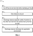
- FIG. 4 illustrates a flow chart depicting steps of a method 41 for operating the burner apparatus depicted in FIG. 1 and FIG. 2 in a second operating mode, in accordance with an embodiment.
- the fuel flow with respect to the burner apparatus 10 can be cut off at one fuel inlet while maintaining the air flow indicated by arrow 4 in FIG. 1 .
- just one mixture e.g., mixture 50
- the discharge sleeves of the burner apparatus 10 can separate the outlets of the swirlers fed by fuel inlet one fuel inlet from the swirlers fed by the other fuel inlet, as indicated at block 64. These discharge sleeves can then discharge into the application environment, as illustrated at block 66.
Landscapes
- Engineering & Computer Science (AREA)
- Chemical & Material Sciences (AREA)
- Combustion & Propulsion (AREA)
- Mechanical Engineering (AREA)
- General Engineering & Computer Science (AREA)
Abstract
Description
- Embodiments are generally related to airfuel gas burners. Embodiments also relate to burners used for industrial heating applications. Embodiments further relate to NOx burners.
- Industrial manufacturers that use thermal processes are under pressure to reduce combustion byproducts, especially NOx (also referred to herein as NOX or NOx) - a collective term for nitric oxide (NO) and nitrogen dioxide (NO2) - to meet tightening global emissions regulations.
- Most of the NOx produced by airfuel burners used in industrial processes comes in the form of thermal NOx. Thermal NOx is strongly correlated to flame temperature and residence time at that temperature. The primary goal of low NOx burner designs is to keep local flame temperatures down. This can be accomplished in a variety of ways with high amounts of excess air, thorough fuel and air mixing, air staging etc.
- Low NOx burners are the most cost-efficient way to reduce an industrial heat process's NOx emissions. A large number of low NOx burners have been developed and are currently used in industrial, plant and other applications. Nevertheless, developmental work continues to enhance the design, and improve the performance of existing burners and engineer and develop new and advanced low NOx burners.
- In low NOx nozzle mix burners for gaseous fuels emissions turndown is generally much less than thermal turndown. In a business environment of tightening emissions requirements this leads to a restricted operating range if a company intends to stay in compliance. If emissions turndown could be improved for a low NOx burner, this could lead to much greater flexibility in operating ranges, and enhanced control of furnace output.
- The following summary is provided to facilitate an understanding of some of the features of the disclosed embodiments and is not intended to be a full description. A full appreciation of the various aspects of the embodiments disclosed herein can be gained by taking the specification, claims, drawings, and abstract as a whole.
- It is, therefore, one aspect of the embodiments to provide for an improved low NOx burner apparatus.
- It is another aspect of the embodiments to provide for a low NOx multi-port air staged burner apparatus.
- It is a further aspect of the embodiments to provide a burner apparatus having multiple low capacity fuel and air swirlers configured in an array in which individual or groups of swirlers of the array can be turned on and off based on a required burner capacity.
- It is also an aspect of the embodiments to provide a burner apparatus that uses discharge sleeves to separate the outlet of a group of swirlers from another, such that fuel can be cut off to one group of swirlers while air flow is maintained, thereby creating an air staged mode of operation for the burner apparatus.
- The aforementioned aspects and other objectives can now be achieved as described herein. In an embodiment, a burner apparatus, can include a housing and an array maintained by the housing and which can function according to an air staged mode of operation. The array can comprise a plurality of low-capacity fuel swirlers and low-capacity air swirlers, wherein individual or groups of the low-capacity fuel swirlers and/or low-capacity air swirlers among the array are turned on or off based on a required burner capacity.
- In an embodiment, the housing can comprise a plurality of discharge sleeves that separates an outlet from the low-capacity fuel swirlers and/or low-capacity air swirlers.
- In an embodiment, fuel can be cut-off to a group among the low-capacity fuel swirlers and/or low-capacity air swirlers while a flow of air is maintained, thereby facilitating the air staged mode of operation.
- In an embodiment, array can be supplied by a common fuel and air source for the fuel and the air.
- In an embodiment, the fuel and the air can be directed to one or more of the low-capacity fuel swirlers and the low-capacity air swirlers at a time.
- In an embodiment, the fuel and the air can be mixed, such that a combustible mixture of the fuel and the air is located downstream from the low-capacity fuel swirlers and the low-capacity air swirlers.
- In an embodiment, a burner apparatus can include an array which functions according to an air staged mode of operation. The array can include a plurality of low-capacity fuel swirlers and low-capacity air swirlers, wherein individual or groups of the low-capacity fuel swirlers and/or low-capacity air swirlers among the array are turned on or off based on a required burner capacity.
- In an embodiment, a method of operating the burner apparatus can involve: operating an array maintained within a housing according to an air staged mode of operation, with the array including a plurality of low-capacity fuel swirlers and low-capacity air swirlers; and turning on or off individual or groups of the low-capacity fuel swirlers and/or low-capacity air swirlers of the array based on a required burner capacity.
- An embodiment of the method can further involve cutting-off fuel to a group among the low-capacity fuel swirlers and/or low-capacity air swirlers while a flow of air is maintained, thereby facilitating the air staged mode of operation.
- An embodiment of the method can further involve supplying the array by a common fuel and air source for the fuel and the air; and directing the fuel and the air to at least one of the low-capacity fuel swirlers and the low-capacity air swirlers at a time.
- The accompanying figures, in which like reference numerals refer to identical or functionally-similar elements throughout the separate views and which are incorporated in and form a part of the specification, further illustrate the present invention and, together with the detailed description of the invention, serve to explain the principles of the present invention.
-
FIG. 1 illustrates a side perspective cut-away view of a burner apparatus, which can be implemented in accordance with an embodiment; -
FIG. 2 illustrates a front perspective view of the burner apparatus depicted inFIG. 1 , in accordance with an embodiment; -
FIG. 3 illustrates a flow chart depicting steps of a method for operating the burner apparatus depicted inFIG. 1 andFIG. 2 in a first operating mode, in accordance with an embodiment; and -
FIG. 4 illustrates a flow chart depicting steps of a method for operating the burner apparatus depicted inFIG. 1 andFIG. 2 in a second operating mode, in accordance with an embodiment. - Like reference symbols or reference numerals in the various drawings indicate like elements.
- The particular values and configurations discussed in these non-limiting examples can be varied and are cited merely to illustrate one or more embodiments and are not intended to limit the scope thereof.
- Subject matter will now be described more fully hereinafter with reference to the accompanying drawings, which form a part hereof, and which show, by way of illustration, specific example embodiments. Subject matter may, however, be embodied in a variety of different forms and, therefore, covered or claimed subject matter is intended to be construed as not being limited to any example embodiments set forth herein; example embodiments are provided merely to be illustrative. Likewise, a reasonably broad scope for claimed or covered subject matter is intended. Among other issues, subject matter may be embodied as methods, devices, components, or systems. Accordingly, embodiments may, for example, take the form of hardware, software, firmware, or a combination thereof. The following detailed description is, therefore, not intended to be interpreted in a limiting sense.
- Throughout the specification and claims, terms may have nuanced meanings suggested or implied in context beyond an explicitly stated meaning. Likewise, phrases such as "in an embodiment" or "in one embodiment" or "in an example embodiment" and variations thereof as utilized herein may or may not necessarily refer to the same embodiment. Similarly, the phrase "in another embodiment" or "in another example embodiment" and variations thereof as utilized herein may or may not necessarily refer to a different embodiment. It is intended, for example, that claimed subject matter may include combinations of example embodiments in whole or in part.
- In general, terminology may be understood, at least in part, from usage in context. For example, terms such as "and," "or," or "and/or" as used herein may include a variety of meanings that may depend, at least in part, upon the context in which such terms are used. Generally, "or" if used to associate a list, such as A, B, or C, is intended to mean A, B, and C, here used in the inclusive sense, as well as A, B, or C, here used in the exclusive sense. In addition, the term "one or more" as used herein, depending at least in part upon context, may be used to describe any feature, structure, or characteristic in a singular sense or may be used to describe combinations of features, structures, or characteristics in a plural sense. Similarly, terms such as "a," "an," or "the", again, may be understood to convey a singular usage or to convey a plural usage, depending at least in part upon context. In addition, the term "based on" may be understood as not necessarily intended to convey an exclusive set of factors and may, instead, allow for existence of additional factors not necessarily expressly described, again, depending at least in part on context.
-
FIG. 1 illustrates a side perspective cut-away view of aburner apparatus 10, which can be implemented in accordance with an embodiment.FIG. 2 illustrates a front perspective view of theburner apparatus 10 depicted inFIG. 1 , in accordance with an embodiment. - The
burner apparatus 10 includes aburner housing 13 and a burnercombustion air sleeve 14. In the embodiment depicted inFIG. 1 andFIG. 2 , air can enter theburner apparatus 10 through anair inlet 13 as indicated by arrow 1 and can be split into flow paths indicated byarrow 2 andarrow 4. The air in the flow path indicated byarrow 2 can enter a centralcombustion air plenum 45 then can be split into swirler air sleeves, 30, 31, 32, 33, 37, 39, 41. The air in flow path indicated byarrow 4 thus can enter theburner housing 13 and can be then split into combustion air sleeves located in anouter ring 22 of combustion air sleeves. Theburner apparatus 10 includes acenter core 20 of theair sleeves outer ring 22 ofair sleeves - The
burner apparatus 10 can include a fuel inlet 7 and a fuel inlet 8. Fuel can enter theburner apparatus 10 through the fuel inlet 7 and the fuel inlet 8 as shown, respectively,arrow 17 andarrow 16. The fuel inlet 7 can lead to afuel vessel 11 and has a path to enter thecenter core 20 of swirlers. The fuel inlet 8 can lead to a fuel vessel 9 and has a path to enter theouter ring 22 of swirlers. Thisouter ring 22 of swirlers can include, for example, theair sleeves center core 20 of swirlers can include, for example, theair sleeves burner face 12 of theburner apparatus 10, forexample flow paths - In another mode of operation of the
burner apparatus 10, the fuel flow can be cut off at the fuel inlet 8 while maintaining the air flow indicated byarrow 4. In this mode of operation, theflow path 5 may only be air. The burner apparatus can also include adischarge sleeve 14 and adischarge sleeve 15, which can separate outlets of the swirlers fed by the fuel inlet 7 from the swirlers fed by the fuel inlet 8.Discharge sleeves - The embodiments are unique in their application of fuel and air swirlers. By arranging multiple low capacity fuel and air swirlers in an array, individual or groups of swirlers can be turned on and off based on a required burner capacity. Turndowns in the range of 40:1, for example, can become possible while still maintaining low NOx. The multiport design of the embodiments can also offer greater flexibility in operating modes. That is, as discussed in greater detail herein first, second and/or additional operating modes may be used. By using properly designed discharge sleeves that can separate the outlet of a group of swirlers from another, for example, fuel can be cut off to one group of swirlers while air flow is maintained, creating an air staged mode of operation.
- The
burner apparatus 10 can thus contain an array of fuel and air swirlers, which can be supplied by a common fuel and air source, whereby the fuel and air can be directed to one or many fuel and air swirlers at a time. The fuel and air swirler of the embodiments can be designed in such a way as to mix the fuel and air so that downstream of the swirler will be a combustible mixture of fuel and air. The outlets of a group of swirlers can be separated from the remaining swirlers. Fuel can be cut off to one group of swirlers and air only passed through that swirler group. -
FIG. 3 illustrates a flow chart depicting steps of amethod 40 for operating theburner apparatus 10 depicted inFIG. 1 andFIG. 2 in a first operating mode, in accordance with an embodiment. It should be appreciated that the sequence of steps and operations of themethod 40 shown inFIG. 3 and themethod 41 shown inFIG. 4 are not limited to the particular sequence depicted inFIG. 3 andFIG. 4 . That is, some steps or operations shown and described herein with respect to the blocks shown inFIG. 3 andFIG. 4 may be performed in a different sequence or even simultaneously. The specific sequence of steps or operations shown inFIG. 2 andFIG. 4 is depicted for exemplary purposes only and should not be considered as a limiting feature of the embodiments. - As shown at
block 40 inFIG. 3 , air can enter theburner apparatus 10 through the air inlet and can be then, as indicated atblock 44, split into two flow paths. Air in the first flow path can enter the combustion air sleeve and can be split into the plurality of swirler air sleeves, as indicated atblock 46. As depicted atblock 48, the air in the second flow path can enters the burner housing and can be split into the plurality of swirler air sleeves. As depicted atblock 50, the fuel can enter the fuel inlets of theburner apparatus 10 with one of the fuel inlets having a path to the center core of theburner apparatus 10 and the other fuel inlet having a path to the outer ring of swirlers of theburner apparatus 10. The air and fuel can be then mixed in each individual swirler as indicated atblock 52. The combustible mixture of air and fuel can then exit each fuel swirler and can be ignited after exiting the burner face of theburner apparatus 10, as described atblock 54. -
FIG. 4 illustrates a flow chart depicting steps of amethod 41 for operating the burner apparatus depicted inFIG. 1 andFIG. 2 in a second operating mode, in accordance with an embodiment. As indicated atblock 60 inFIG. 4 , the fuel flow with respect to theburner apparatus 10 can be cut off at one fuel inlet while maintaining the air flow indicated byarrow 4 inFIG. 1 . In this mode of operation, just one mixture (e.g., mixture 50) may comprise only air, as depicted atblock 62. The discharge sleeves of theburner apparatus 10 can separate the outlets of the swirlers fed by fuel inlet one fuel inlet from the swirlers fed by the other fuel inlet, as indicated atblock 64. These discharge sleeves can then discharge into the application environment, as illustrated atblock 66. - It will be appreciated that variations of the above-disclosed and other features and functions, or alternatives thereof, may be desirably combined into many other different systems or applications. It will also be appreciated that various presently unforeseen or unanticipated alternatives, modifications, variations or improvements therein may be subsequently made by those skilled in the art which are also intended to be encompassed by the following claims.
Claims (10)
- A burner apparatus, comprising:a housing; andan array maintained by the housing and which functions according to an air staged mode of operation, the array comprising a plurality of low-capacity fuel swirlers and low-capacity air swirlers, wherein individual or groups of the low-capacity fuel swirlers and/or low-capacity air swirlers among the array are turned on or off based on a required burner capacity.
- The burner apparatus of claim 1, wherein the housing comprises a plurality of discharge sleeves that separates an outlet from the low-capacity fuel swirlers and/or low-capacity air swirlers.
- The burner apparatus of claim 2, wherein fuel is cut-off to a group among the low-capacity fuel swirlers and/or low-capacity air swirlers while a flow of air is maintained, thereby facilitating the air staged mode of operation.
- The burner apparatus of claim 3, wherein the array is supplied by a common fuel and air source for the fuel and the air.
- The burner apparatus of claim 3, wherein the fuel and the air are directed to at least one of the low-capacity fuel swirlers and the low-capacity air swirlers at a time.
- The burner apparatus of claim 3 wherein the fuel and the air is mixed.
- A burner apparatus, comprising:
an array which functions according to an air staged mode of operation, the array comprising a plurality of low-capacity fuel swirlers and low-capacity air swirlers, wherein individual or groups of the low-capacity fuel swirlers and/or low-capacity air swirlers among the array are turned on or off based on a required burner capacity. - The burner apparatus of claim 7 further comprising comprises a plurality of discharge sleeves that separates an outlet from the low-capacity fuel swirlers and/or low-capacity air swirlers.
- A method of operating a burner apparatus, comprising:operating an array maintained within a housing according to an air staged mode of operation, the array comprising a plurality of low-capacity fuel swirlers and low-capacity air swirlers; andturning on or off individual or groups of the low-capacity fuel swirlers and/or low-capacity air swirlers among the array based on a required burner capacity.
- The method of claim 9, wherein the housing comprises a plurality of discharge sleeves that separates an outlet from the low-capacity fuel swirlers and/or low-capacity air swirlers.
Applications Claiming Priority (1)
| Application Number | Priority Date | Filing Date | Title |
|---|---|---|---|
| US17/677,680 US12385637B2 (en) | 2022-02-22 | 2022-02-22 | Ultra-low NOx multi-port air staged burner apparatus |
Publications (2)
| Publication Number | Publication Date |
|---|---|
| EP4230908A1 true EP4230908A1 (en) | 2023-08-23 |
| EP4230908B1 EP4230908B1 (en) | 2026-01-21 |
Family
ID=85173118
Family Applications (1)
| Application Number | Title | Priority Date | Filing Date |
|---|---|---|---|
| EP23154668.0A Active EP4230908B1 (en) | 2022-02-22 | 2023-02-02 | Ultra-low nox multi-port air staged burner apparatus |
Country Status (3)
| Country | Link |
|---|---|
| US (1) | US12385637B2 (en) |
| EP (1) | EP4230908B1 (en) |
| CN (1) | CN116677994A (en) |
Citations (2)
| Publication number | Priority date | Publication date | Assignee | Title |
|---|---|---|---|---|
| US5660045A (en) * | 1994-07-20 | 1997-08-26 | Hitachi, Ltd. | Gas turbine combustor and gas turbine |
| EP1106928A1 (en) * | 1999-12-08 | 2001-06-13 | General Electric Company | Fuel system configuration and method for staging fuel for gas turbines utilizing both gaseous and liquid fuels |
Family Cites Families (15)
| Publication number | Priority date | Publication date | Assignee | Title |
|---|---|---|---|---|
| US6962055B2 (en) * | 2002-09-27 | 2005-11-08 | United Technologies Corporation | Multi-point staging strategy for low emission and stable combustion |
| US7836698B2 (en) * | 2005-10-20 | 2010-11-23 | General Electric Company | Combustor with staged fuel premixer |
| EP2154432A1 (en) | 2008-08-05 | 2010-02-17 | Siemens Aktiengesellschaft | Swirler for mixing fuel and air |
| US8961169B2 (en) * | 2011-03-29 | 2015-02-24 | Fives North American Combustion, Inc. | High uniformity heating |
| JP5897364B2 (en) * | 2012-03-21 | 2016-03-30 | 川崎重工業株式会社 | Pulverized coal biomass mixed burner |
| CA2808707C (en) * | 2012-11-23 | 2014-02-11 | Charles Tremblay | Gas flare system and method of destroying a flammable gas in a waste gas stream |
| US9677758B2 (en) | 2013-09-06 | 2017-06-13 | Honeywell International Inc. | Gaseous fuel-oxygen burner |
| EP3236157A1 (en) | 2016-04-22 | 2017-10-25 | Siemens Aktiengesellschaft | Swirler for mixing fuel with air in a combustion engine |
| US10584051B2 (en) | 2017-02-22 | 2020-03-10 | Air Products And Chemicals, Inc. | Double-staged oxy-fuel burner |
| CN110709336B (en) | 2017-04-28 | 2022-06-03 | 织宽植物露水株式会社 | Pillow type packaging bag filled with content |
| CN108167826A (en) * | 2017-12-29 | 2018-06-15 | 浙江百能科技有限公司 | A kind of turbulent burner for being used for fuel oil or gas steam injection boiler |
| US10920979B2 (en) | 2018-04-06 | 2021-02-16 | Zeeco, Inc. | Low NOx burner and flow momentum enhancing device |
| EP3617599A1 (en) | 2018-09-03 | 2020-03-04 | Siemens Aktiengesellschaft | Burner with improved air-fuel mixing |
| CN109442403B (en) * | 2018-11-21 | 2023-12-05 | 中国科学院工程热物理研究所 | Double-rotary burner and combustion control method |
| CN111810951B (en) | 2020-07-17 | 2022-06-28 | 北京泷涛环境科技有限公司 | Environment-friendly combustor with ultralow nitrogen oxide emission |
-
2022
- 2022-02-22 US US17/677,680 patent/US12385637B2/en active Active
-
2023
- 2023-02-01 CN CN202310050036.XA patent/CN116677994A/en active Pending
- 2023-02-02 EP EP23154668.0A patent/EP4230908B1/en active Active
Patent Citations (2)
| Publication number | Priority date | Publication date | Assignee | Title |
|---|---|---|---|---|
| US5660045A (en) * | 1994-07-20 | 1997-08-26 | Hitachi, Ltd. | Gas turbine combustor and gas turbine |
| EP1106928A1 (en) * | 1999-12-08 | 2001-06-13 | General Electric Company | Fuel system configuration and method for staging fuel for gas turbines utilizing both gaseous and liquid fuels |
Also Published As
| Publication number | Publication date |
|---|---|
| US12385637B2 (en) | 2025-08-12 |
| EP4230908B1 (en) | 2026-01-21 |
| CN116677994A (en) | 2023-09-01 |
| US20230266004A1 (en) | 2023-08-24 |
Similar Documents
| Publication | Publication Date | Title |
|---|---|---|
| CA2632012C (en) | Method and apparatus for reducing nox emissions in a gas burner | |
| EP2975325B1 (en) | Gas turbine combustor | |
| US7165405B2 (en) | Fully premixed secondary fuel nozzle with dual fuel capability | |
| US8607568B2 (en) | Dry low NOx combustion system with pre-mixed direct-injection secondary fuel nozzle | |
| US6722132B2 (en) | Fully premixed secondary fuel nozzle with improved stability and dual fuel capability | |
| EP2306090B1 (en) | Gas turbine combustor | |
| US6871501B2 (en) | Method and apparatus to decrease gas turbine engine combustor emissions | |
| US8117845B2 (en) | Systems to facilitate reducing flashback/flame holding in combustion systems | |
| US6374593B1 (en) | Burner and method for reducing combustion humming during operation | |
| US10101032B2 (en) | Micromixer system for a turbine system and an associated method thereof | |
| US7837462B2 (en) | Combustion method and apparatus | |
| US9885481B2 (en) | Sequential combustion with dilution gas mixer | |
| US20120011854A1 (en) | Flame tolerant secondary fuel nozzle | |
| EP0672865A2 (en) | A fuel nozzle for a turbine having dual capability for diffusion and premix combustion and methods of operation | |
| US20160290646A1 (en) | Gas Turbine Combustor | |
| EP1193447B1 (en) | Multiple injector combustor | |
| KR20150065782A (en) | Combustor with radially staged premixed pilot for improved operability | |
| EP3502566A1 (en) | Dual fuel gas turbine engine pilot nozzles | |
| US10823420B2 (en) | Pilot nozzle with inline premixing | |
| US8596074B2 (en) | Gas turbine combustor | |
| EP4230909A1 (en) | Ultra-low nox multi-port burner apparatus | |
| US12385637B2 (en) | Ultra-low NOx multi-port air staged burner apparatus | |
| US11815264B2 (en) | Burner | |
| KR102298340B1 (en) | Burner apparatus reducing nitrogen oxide emission | |
| JP2002206710A (en) | Premix combustor |
Legal Events
| Date | Code | Title | Description |
|---|---|---|---|
| PUAI | Public reference made under article 153(3) epc to a published international application that has entered the european phase |
Free format text: ORIGINAL CODE: 0009012 |
|
| STAA | Information on the status of an ep patent application or granted ep patent |
Free format text: STATUS: REQUEST FOR EXAMINATION WAS MADE |
|
| 17P | Request for examination filed |
Effective date: 20230202 |
|
| AK | Designated contracting states |
Kind code of ref document: A1 Designated state(s): AL AT BE BG CH CY CZ DE DK EE ES FI FR GB GR HR HU IE IS IT LI LT LU LV MC ME MK MT NL NO PL PT RO RS SE SI SK SM TR |
|
| STAA | Information on the status of an ep patent application or granted ep patent |
Free format text: STATUS: EXAMINATION IS IN PROGRESS |
|
| 17Q | First examination report despatched |
Effective date: 20241212 |
|
| GRAP | Despatch of communication of intention to grant a patent |
Free format text: ORIGINAL CODE: EPIDOSNIGR1 |
|
| STAA | Information on the status of an ep patent application or granted ep patent |
Free format text: STATUS: GRANT OF PATENT IS INTENDED |
|
| INTG | Intention to grant announced |
Effective date: 20250903 |
|
| GRAS | Grant fee paid |
Free format text: ORIGINAL CODE: EPIDOSNIGR3 |
|
| GRAA | (expected) grant |
Free format text: ORIGINAL CODE: 0009210 |
|
| STAA | Information on the status of an ep patent application or granted ep patent |
Free format text: STATUS: THE PATENT HAS BEEN GRANTED |
|
| AK | Designated contracting states |
Kind code of ref document: B1 Designated state(s): AL AT BE BG CH CY CZ DE DK EE ES FI FR GB GR HR HU IE IS IT LI LT LU LV MC ME MK MT NL NO PL PT RO RS SE SI SK SM TR |
|
| REG | Reference to a national code |
Ref country code: CH Ref legal event code: F10 Free format text: ST27 STATUS EVENT CODE: U-0-0-F10-F00 (AS PROVIDED BY THE NATIONAL OFFICE) Effective date: 20260121 |
|
| REG | Reference to a national code |
Ref country code: DE Ref legal event code: R096 Ref document number: 602023010857 Country of ref document: DE |
|
| REG | Reference to a national code |
Ref country code: IE Ref legal event code: FG4D |
|
| PGFP | Annual fee paid to national office [announced via postgrant information from national office to epo] |
Ref country code: DE Payment date: 20260227 Year of fee payment: 4 |
|
| PGFP | Annual fee paid to national office [announced via postgrant information from national office to epo] |
Ref country code: AT Payment date: 20260301 Year of fee payment: 4 |
|
| PGFP | Annual fee paid to national office [announced via postgrant information from national office to epo] |
Ref country code: FR Payment date: 20260227 Year of fee payment: 4 |
|
| REG | Reference to a national code |
Ref country code: NL Ref legal event code: MP Effective date: 20260121 |
|
| PG25 | Lapsed in a contracting state [announced via postgrant information from national office to epo] |
Ref country code: NL Free format text: LAPSE BECAUSE OF FAILURE TO SUBMIT A TRANSLATION OF THE DESCRIPTION OR TO PAY THE FEE WITHIN THE PRESCRIBED TIME-LIMIT Effective date: 20260121 |
|
| REG | Reference to a national code |
Ref country code: AT Ref legal event code: MK05 Ref document number: 1878998 Country of ref document: AT Kind code of ref document: T Effective date: 20260121 |
|
| PG25 | Lapsed in a contracting state [announced via postgrant information from national office to epo] |
Ref country code: RS Free format text: LAPSE BECAUSE OF FAILURE TO SUBMIT A TRANSLATION OF THE DESCRIPTION OR TO PAY THE FEE WITHIN THE PRESCRIBED TIME-LIMIT Effective date: 20260421 |
|
| PG25 | Lapsed in a contracting state [announced via postgrant information from national office to epo] |
Ref country code: ES Free format text: LAPSE BECAUSE OF FAILURE TO SUBMIT A TRANSLATION OF THE DESCRIPTION OR TO PAY THE FEE WITHIN THE PRESCRIBED TIME-LIMIT Effective date: 20260121 |
|
| PG25 | Lapsed in a contracting state [announced via postgrant information from national office to epo] |
Ref country code: PL Free format text: LAPSE BECAUSE OF FAILURE TO SUBMIT A TRANSLATION OF THE DESCRIPTION OR TO PAY THE FEE WITHIN THE PRESCRIBED TIME-LIMIT Effective date: 20260121 |
|
| PG25 | Lapsed in a contracting state [announced via postgrant information from national office to epo] |
Ref country code: GR Free format text: LAPSE BECAUSE OF FAILURE TO SUBMIT A TRANSLATION OF THE DESCRIPTION OR TO PAY THE FEE WITHIN THE PRESCRIBED TIME-LIMIT Effective date: 20260422 |
|
| REG | Reference to a national code |
Ref country code: LT Ref legal event code: MG9D |
|
| PG25 | Lapsed in a contracting state [announced via postgrant information from national office to epo] |
Ref country code: LT Free format text: LAPSE BECAUSE OF FAILURE TO SUBMIT A TRANSLATION OF THE DESCRIPTION OR TO PAY THE FEE WITHIN THE PRESCRIBED TIME-LIMIT Effective date: 20260121 |
|
| PG25 | Lapsed in a contracting state [announced via postgrant information from national office to epo] |
Ref country code: NO Free format text: LAPSE BECAUSE OF FAILURE TO SUBMIT A TRANSLATION OF THE DESCRIPTION OR TO PAY THE FEE WITHIN THE PRESCRIBED TIME-LIMIT Effective date: 20260421 |
|
| PG25 | Lapsed in a contracting state [announced via postgrant information from national office to epo] |
Ref country code: FI Free format text: LAPSE BECAUSE OF FAILURE TO SUBMIT A TRANSLATION OF THE DESCRIPTION OR TO PAY THE FEE WITHIN THE PRESCRIBED TIME-LIMIT Effective date: 20260121 Ref country code: AT Free format text: LAPSE BECAUSE OF FAILURE TO SUBMIT A TRANSLATION OF THE DESCRIPTION OR TO PAY THE FEE WITHIN THE PRESCRIBED TIME-LIMIT Effective date: 20260121 Ref country code: SE Free format text: LAPSE BECAUSE OF FAILURE TO SUBMIT A TRANSLATION OF THE DESCRIPTION OR TO PAY THE FEE WITHIN THE PRESCRIBED TIME-LIMIT Effective date: 20260121 |
|
| PG25 | Lapsed in a contracting state [announced via postgrant information from national office to epo] |
Ref country code: HR Free format text: LAPSE BECAUSE OF FAILURE TO SUBMIT A TRANSLATION OF THE DESCRIPTION OR TO PAY THE FEE WITHIN THE PRESCRIBED TIME-LIMIT Effective date: 20260121 |
|
| PG25 | Lapsed in a contracting state [announced via postgrant information from national office to epo] |
Ref country code: IS Free format text: LAPSE BECAUSE OF FAILURE TO SUBMIT A TRANSLATION OF THE DESCRIPTION OR TO PAY THE FEE WITHIN THE PRESCRIBED TIME-LIMIT Effective date: 20260521 Ref country code: PT Free format text: LAPSE BECAUSE OF FAILURE TO SUBMIT A TRANSLATION OF THE DESCRIPTION OR TO PAY THE FEE WITHIN THE PRESCRIBED TIME-LIMIT Effective date: 20260521 |
|
| PG25 | Lapsed in a contracting state [announced via postgrant information from national office to epo] |
Ref country code: LV Free format text: LAPSE BECAUSE OF FAILURE TO SUBMIT A TRANSLATION OF THE DESCRIPTION OR TO PAY THE FEE WITHIN THE PRESCRIBED TIME-LIMIT Effective date: 20260121 |
|
| PG25 | Lapsed in a contracting state [announced via postgrant information from national office to epo] |
Ref country code: BG Free format text: LAPSE BECAUSE OF FAILURE TO SUBMIT A TRANSLATION OF THE DESCRIPTION OR TO PAY THE FEE WITHIN THE PRESCRIBED TIME-LIMIT Effective date: 20260121 |