EP4230851A1 - Engine - Google Patents
Engine Download PDFInfo
- Publication number
- EP4230851A1 EP4230851A1 EP23155715.8A EP23155715A EP4230851A1 EP 4230851 A1 EP4230851 A1 EP 4230851A1 EP 23155715 A EP23155715 A EP 23155715A EP 4230851 A1 EP4230851 A1 EP 4230851A1
- Authority
- EP
- European Patent Office
- Prior art keywords
- pipe
- sacrificial protective
- metal
- flow path
- sacrificial
- Prior art date
- Legal status (The legal status is an assumption and is not a legal conclusion. Google has not performed a legal analysis and makes no representation as to the accuracy of the status listed.)
- Pending
Links
Images



Classifications
-
- F—MECHANICAL ENGINEERING; LIGHTING; HEATING; WEAPONS; BLASTING
- F01—MACHINES OR ENGINES IN GENERAL; ENGINE PLANTS IN GENERAL; STEAM ENGINES
- F01P—COOLING OF MACHINES OR ENGINES IN GENERAL; COOLING OF INTERNAL-COMBUSTION ENGINES
- F01P11/00—Component parts, details, or accessories not provided for in, or of interest apart from, groups F01P1/00 - F01P9/00
- F01P11/06—Cleaning; Combating corrosion
-
- C—CHEMISTRY; METALLURGY
- C23—COATING METALLIC MATERIAL; COATING MATERIAL WITH METALLIC MATERIAL; CHEMICAL SURFACE TREATMENT; DIFFUSION TREATMENT OF METALLIC MATERIAL; COATING BY VACUUM EVAPORATION, BY SPUTTERING, BY ION IMPLANTATION OR BY CHEMICAL VAPOUR DEPOSITION, IN GENERAL; INHIBITING CORROSION OF METALLIC MATERIAL OR INCRUSTATION IN GENERAL
- C23F—NON-MECHANICAL REMOVAL OF METALLIC MATERIAL FROM SURFACE; INHIBITING CORROSION OF METALLIC MATERIAL OR INCRUSTATION IN GENERAL; MULTI-STEP PROCESSES FOR SURFACE TREATMENT OF METALLIC MATERIAL INVOLVING AT LEAST ONE PROCESS PROVIDED FOR IN CLASS C23 AND AT LEAST ONE PROCESS COVERED BY SUBCLASS C21D OR C22F OR CLASS C25
- C23F13/00—Inhibiting corrosion of metals by anodic or cathodic protection
- C23F13/02—Inhibiting corrosion of metals by anodic or cathodic protection cathodic; Selection of conditions, parameters or procedures for cathodic protection, e.g. of electrical conditions
- C23F13/06—Constructional parts, or assemblies of cathodic-protection apparatus
-
- C—CHEMISTRY; METALLURGY
- C23—COATING METALLIC MATERIAL; COATING MATERIAL WITH METALLIC MATERIAL; CHEMICAL SURFACE TREATMENT; DIFFUSION TREATMENT OF METALLIC MATERIAL; COATING BY VACUUM EVAPORATION, BY SPUTTERING, BY ION IMPLANTATION OR BY CHEMICAL VAPOUR DEPOSITION, IN GENERAL; INHIBITING CORROSION OF METALLIC MATERIAL OR INCRUSTATION IN GENERAL
- C23F—NON-MECHANICAL REMOVAL OF METALLIC MATERIAL FROM SURFACE; INHIBITING CORROSION OF METALLIC MATERIAL OR INCRUSTATION IN GENERAL; MULTI-STEP PROCESSES FOR SURFACE TREATMENT OF METALLIC MATERIAL INVOLVING AT LEAST ONE PROCESS PROVIDED FOR IN CLASS C23 AND AT LEAST ONE PROCESS COVERED BY SUBCLASS C21D OR C22F OR CLASS C25
- C23F13/00—Inhibiting corrosion of metals by anodic or cathodic protection
- C23F13/02—Inhibiting corrosion of metals by anodic or cathodic protection cathodic; Selection of conditions, parameters or procedures for cathodic protection, e.g. of electrical conditions
- C23F13/06—Constructional parts, or assemblies of cathodic-protection apparatus
- C23F13/08—Electrodes specially adapted for inhibiting corrosion by cathodic protection; Manufacture thereof; Conducting electric current thereto
- C23F13/12—Electrodes characterised by the material
-
- F—MECHANICAL ENGINEERING; LIGHTING; HEATING; WEAPONS; BLASTING
- F01—MACHINES OR ENGINES IN GENERAL; ENGINE PLANTS IN GENERAL; STEAM ENGINES
- F01P—COOLING OF MACHINES OR ENGINES IN GENERAL; COOLING OF INTERNAL-COMBUSTION ENGINES
- F01P11/00—Component parts, details, or accessories not provided for in, or of interest apart from, groups F01P1/00 - F01P9/00
- F01P11/04—Arrangements of liquid pipes or hoses
-
- F—MECHANICAL ENGINEERING; LIGHTING; HEATING; WEAPONS; BLASTING
- F01—MACHINES OR ENGINES IN GENERAL; ENGINE PLANTS IN GENERAL; STEAM ENGINES
- F01P—COOLING OF MACHINES OR ENGINES IN GENERAL; COOLING OF INTERNAL-COMBUSTION ENGINES
- F01P3/00—Liquid cooling
- F01P3/20—Cooling circuits not specific to a single part of engine or machine
-
- C—CHEMISTRY; METALLURGY
- C23—COATING METALLIC MATERIAL; COATING MATERIAL WITH METALLIC MATERIAL; CHEMICAL SURFACE TREATMENT; DIFFUSION TREATMENT OF METALLIC MATERIAL; COATING BY VACUUM EVAPORATION, BY SPUTTERING, BY ION IMPLANTATION OR BY CHEMICAL VAPOUR DEPOSITION, IN GENERAL; INHIBITING CORROSION OF METALLIC MATERIAL OR INCRUSTATION IN GENERAL
- C23F—NON-MECHANICAL REMOVAL OF METALLIC MATERIAL FROM SURFACE; INHIBITING CORROSION OF METALLIC MATERIAL OR INCRUSTATION IN GENERAL; MULTI-STEP PROCESSES FOR SURFACE TREATMENT OF METALLIC MATERIAL INVOLVING AT LEAST ONE PROCESS PROVIDED FOR IN CLASS C23 AND AT LEAST ONE PROCESS COVERED BY SUBCLASS C21D OR C22F OR CLASS C25
- C23F2213/00—Aspects of inhibiting corrosion of metals by anodic or cathodic protection
- C23F2213/30—Anodic or cathodic protection specially adapted for a specific object
-
- F—MECHANICAL ENGINEERING; LIGHTING; HEATING; WEAPONS; BLASTING
- F01—MACHINES OR ENGINES IN GENERAL; ENGINE PLANTS IN GENERAL; STEAM ENGINES
- F01P—COOLING OF MACHINES OR ENGINES IN GENERAL; COOLING OF INTERNAL-COMBUSTION ENGINES
- F01P11/00—Component parts, details, or accessories not provided for in, or of interest apart from, groups F01P1/00 - F01P9/00
- F01P11/06—Cleaning; Combating corrosion
- F01P2011/066—Combating corrosion
- F01P2011/068—Combating corrosion chemically
-
- F—MECHANICAL ENGINEERING; LIGHTING; HEATING; WEAPONS; BLASTING
- F01—MACHINES OR ENGINES IN GENERAL; ENGINE PLANTS IN GENERAL; STEAM ENGINES
- F01P—COOLING OF MACHINES OR ENGINES IN GENERAL; COOLING OF INTERNAL-COMBUSTION ENGINES
- F01P2050/00—Applications
- F01P2050/02—Marine engines
- F01P2050/06—Marine engines using liquid-to-liquid heat exchangers
-
- F—MECHANICAL ENGINEERING; LIGHTING; HEATING; WEAPONS; BLASTING
- F01—MACHINES OR ENGINES IN GENERAL; ENGINE PLANTS IN GENERAL; STEAM ENGINES
- F01P—COOLING OF MACHINES OR ENGINES IN GENERAL; COOLING OF INTERNAL-COMBUSTION ENGINES
- F01P3/00—Liquid cooling
- F01P3/20—Cooling circuits not specific to a single part of engine or machine
- F01P3/207—Cooling circuits not specific to a single part of engine or machine liquid-to-liquid heat-exchanging relative to marine vessels
Definitions
- the present invention relates to an engine.
- Patent Document 1 describes placing an anticorrosive zinc in an intercooler.
- Patent Document 2 describes forming an anticorrosive coating inside a cooling pipe.
- an object of the present invention is to provide an engine that can reduce the burden of maintenance for preventing corrosion of a pipe.
- an engine according to the present invention includes: a sacrificial protective pipe subjected to a sacrificial protective coating process; and a metal pipe connected to at least one of two ends of the sacrificial protective pipe.
- the engine may include: a flow path component connected to one of two ends of the metal pipe, the one not being connected to the sacrificial protective pipe; and a sacrificial protective material provided to the flow path component.
- the sacrificial protective pipe, the metal pipes, and the flow path components each including the sacrificial protective material may be connected in an order of the flow path component including the sacrificial protective material, the metal pipe, the sacrificial protective pipe, the metal pipe, and the flow path component including the sacrificial protective material.
- the plurality of metal pipes may have a same shape.
- the sacrificial protective pipe may be connected to the metal pipe via a connecting pipe, and the connecting pipe may be slidable along a longitudinal direction of the metal pipe or the sacrificial protective pipe.
- the sacrificial protective coating process may be a galvanizing process, and the metal pipe may be formed of iron.
- the engine may include: a flow path component connected to one of two ends of the metal pipe, the one not being connected to the sacrificial protective pipe; and a sacrificial protective material provided to the flow path component, in which the sacrificial protective material may be formed of zinc or iron.
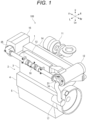
- Fig. 1 is a perspective view illustrating the engine 100.
- U, Lo, L, R, Fr, and Rr denote up, down, left, right, front, and back, respectively.
- the engine 100 may be used in any attitude.
- an inline-six diesel engine appears, as an example of an application target of the present invention, in the embodiment.
- the present invention is suitable for all reciprocating engines with a plurality of cylinders.
- the engine 100 includes the cylinder head 1, the cylinder block 2, and an oil pan 5.
- the cylinder head 1 six component groups (not illustrated) including an air intake path, an exhaust path, an intake valve, an exhaust valve, and an injector are placed in series along a front-and-back direction.
- the cylinder block 2 includes: a cylinder row 3 in which six cylinders (not illustrated) housing a piston and a connecting rod are placed in series along the front-and-back direction; and a crankcase 4 housing a crankshaft (not illustrated).
- the oil pan 5 stores lubricating oil.
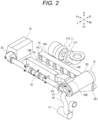
- FIGs. 2 and 3 are perspective views illustrating the air intake and exhaust paths.
- the air intake and exhaust paths include a turbocharger 11, an intercooler 12, an intake manifold 13, the cylinder head 1, and an exhaust manifold 14.
- the turbocharger 11 includes a turbine 11T and a compressor 11C.
- the compressor 11C is connected to the intercooler 12.
- the intake manifold 13 includes a main body portion 13B, an air intake inlet port 13i, and six air intake passages 13E.
- the air intake inlet port 13i is connected to the intercooler 12.
- the six air intake passages 13E are connected to the air intake path (not illustrated) of the cylinder head 1.
- the exhaust manifold 14 includes a collector 14C, six exhaust inlet ports 14i, and an exhaust outlet port 14E.
- the six exhaust inlet ports 14i are connected to the exhaust path (not illustrated) of the cylinder head 1.
- the exhaust outlet port 14E is connected to the turbine 11T.
- Exhaust gases from the cylinders are supplied to the turbine 11T through the exhaust path of the cylinder head 1 and the exhaust manifold 14.
- the turbine 11T rotates by exhaust energy.
- the compressor 11C rotates together with the turbine 11T to take in and compress air.
- the compressed air is sent to the intercooler 12.
- the intercooler 12 cools the compressed air and sends the compressed air to the intake manifold 13.
- the intake manifold 13 has a function of a surge tank that equalizes the density, intake volume, and stream of the compressed air supplied to each cylinder, and supplies the compressed air to the air intake path of the cylinder head 1 through the air intake passages 13E.
- FIG. 4 is a perspective view illustrating the cooling pipe 18.
- a feed water pipe 16 including a pump 17 is connected to the intercooler 12.
- the intercooler 12 cools intake air with seawater sucked up by the pump 17.
- a fresh-water cooler 15 is connected to the intercooler 12 via the cooling pipe 18.
- the seawater used to cool the intake air in the intercooler 12 is supplied to the fresh-water cooler 15 through the cooling pipe 18.
- the fresh-water cooler 15 cools coolant circulating in a water jacket (not illustrated) provided to the engine 100, with the seawater supplied from the intercooler 12.
- the seawater used to cool the coolant in the fresh-water cooler 15 is used to cool the lubricating oil in an oil cooler (not illustrated) and then discharged to the outside of the ship.
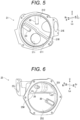
- Fig. 5 is a perspective view illustrating an intercooler side cover 21.
- Fig. 6 is a perspective view illustrating a fresh-water cooler side cover 25.
- Fig. 7 is a perspective view illustrating the main elements of the cooling pipe 18.
- Fig. 8 is an exploded view illustrating the main elements of the cooling pipe 18.
- Fig. 9 is a side view illustrating the main elements of the cooling pipe 18.
- connecting pipes 23 and metal pipes 22 are provided in front of and behind a sacrificial protective pipe 24.
- Fig. 8 only the sacrificial protective pipe 24, and the connecting pipe 23 and the metal pipe 22 that are in front of the sacrificial protective pipe 24 are illustrated.
- the engine 100 includes the sacrificial protective pipe 24 that has been subjected to a sacrificial protective coating process, and the metal pipe 22 connected to at least one of two ends of the sacrificial protective pipe 24.
- the intercooler 12 (refer to Figs. 4 and 5 ) includes an intercooler housing 20 and the intercooler side cover 21 (an example of a flow path component) that blocks an opening (not illustrated) provided in the left side of the intercooler housing 20.
- the intercooler housing 20 includes an air intake inlet port 20i and an air intake outlet port 20E.
- the air intake inlet port 20i is provided in a portion on the right side of the bottom of the intercooler housing 20.
- the air intake outlet port 20E is provided in a portion that is further to the left than the center of the intercooler housing 20 in the left-and-right direction.
- the air intake outlet port 20E opens to the front and upward.
- the intercooler side cover 21 is substantially circular and recessed leftward. A space inside the intercooler side cover 21 is divided by a partition wall 21W into a first auxiliary chamber 211 on the bottom and a second auxiliary chamber 212 on the top.
- the first auxiliary chamber 211 is provided with a liquid inlet port 21i penetrating in the left-and-right direction. The liquid inlet port 21i is connected to the feed water pipe 16.
- the second auxiliary chamber 212 is provided with a liquid outlet port 21E penetrating in the front-and-back direction. The liquid outlet port 21E is connected to the back end of the cooling pipe 18.
- the first auxiliary chamber 211 and the second auxiliary chamber 212 are each provided with an insertion port (not illustrated) penetrating from the inside through to the outside.
- a female thread is formed in each of the insertion ports.
- a bolt-shaped sacrificial protective material 30 with a male thread is mounted in the each of the insertion ports.
- the sacrificial protective material 30 protrudes from the inner surface of each of the first auxiliary chamber 211 and the second auxiliary chamber 212.
- the sacrificial protective material 30 is formed of zinc or iron. Zinc that contains, as a main raw material, high-purity zinc metal with a purity equal to or greater than 99.99% is used. Iron that is pure iron with a purity equal to or greater than 99.90% is used.
- the fresh-water cooler 15 (refer to Figs. 4 and 6 ) includes a fresh-water cooler housing 26 and the fresh-water cooler side cover 25 (an example of the flow path component) that blocks an opening (not illustrated) provided in the left side of the fresh-water cooler housing 26.
- the fresh-water cooler side cover 25 is substantially circular and recessed leftward.
- a space inside the fresh-water cooler side cover 25 is divided by a partition wall 25W into a first auxiliary chamber 251 on the top and a second auxiliary chamber 252 on the bottom.
- the first auxiliary chamber 251 is provided with a liquid inlet port 25i penetrating in the front-and-back direction.
- the liquid inlet port 25i is connected to the front end of the cooling pipe 18.
- the first auxiliary chamber 251 and the second auxiliary chamber 252 are each provided with an insertion port (not illustrated) penetrating from the inside through to the outside.
- a female thread is formed in each of the insertion ports.
- the above-mentioned sacrificial protective material 30 is mounted in the each of the insertion ports. The sacrificial protective material 30 protrudes from the inner surface of each of the first auxiliary chamber 251 and the second auxiliary chamber 252.
- the cooling pipe 18 (refer to Figs. 4 and 7 to 9 ) includes the metal pipes 22 and the sacrificial protective pipe 24. Seawater flows from the intercooler 12 to the fresh-water cooler 15 through the cooling pipe 18.
- the metal pipes 22, the sacrificial protective pipe 24, the intercooler side cover 21, and the fresh-water cooler side cover 25 are placed in the order of the intercooler side cover 21, the metal pipe 22, the sacrificial protective pipe 24, the metal pipe 22, and the fresh-water cooler side cover 25 from the back.
- the metal pipes 22 are formed of iron. Sacrificial protective coatings are not formed on the inner peripheral surfaces of the metal pipes 22.
- the metal pipes 22 in front of and behind the sacrificial protective pipe 24 have the same shape.
- the metal pipes 22 are at least configured in such a manner as to have a common shape at two ends of each of the metal pipes 22 and a common length and to be interchangeable as a cooling water pipe. As long as being interchangeable as a cooling water pipe, the metal pipes 22 are regarded as having the same shape even if the shape and placement of a boss formed on the pipe surface are different.
- the each of the metal pipes 22 includes a pipe portion 22P, a flange 22F provided at one end of the pipe portion 22P in the front-and-back direction, and a sleeve 22S provided at the other end of the pipe portion 22P.
- the inner diameter of the sleeves 22S is greater than the inner diameter of the pipe portions 22P.
- the flange 22F of the metal pipe 22 near the intercooler 12 is fastened to the liquid outlet port 21E of the intercooler side cover 21 by a bolt via a gasket or an O-ring (neither illustrated).
- the flange 22F of the metal pipe 22 near the fresh-water cooler 15 is fastened to the liquid inlet port 25i of the fresh-water cooler side cover 25 by a bolt via a gasket or an O-ring (neither illustrated).
- a bolt insertion portion 22A is provided in the vicinity of an end of the pipe portion 22P of the each of the metal pipes 22, the end being near the respective sleeve 22S (refer to Figs. 7 and 8 ).
- Each of the bolt insertion portions 22A is a portion expanding upward and downward from the outer peripheral surface of the respective pipe portion 22P.
- the each of the bolt insertion portions 22A is provided with a bolt hole penetrating in the left-and-right direction.
- a female thread is provided in the left side surface of the main body portion 13B of the intake manifold 13, in a position corresponding to each of the bolt holes of the bolt insertion portions 22A (not illustrated).
- the metal pipes 22 are fastened to the intake manifold 13 by bolts to be fixed to the intake manifold 13 (refer to Fig. 2 ).
- the sacrificial protective pipe 24 is formed of iron.
- the sacrificial protective pipe 24 includes a pipe portion 24P, and a flange 24F provided at each end of the pipe portion 24P.
- the inner surface of the sacrificial protective pipe 24 has been subjected to a galvanizing process such as hot-dip galvanizing or electrogalvanizing.
- Zinc that contains, as a main raw material, high-purity zinc metal with a purity equal to or greater than 99.99% is used.
- Each of the connecting pipes 23 includes a pipe portion 23P, and a flange 23F provided at one end of the pipe portion 23P in the front-and-back direction.
- a groove 23G in which an O-ring 23R (refer to Fig. 9 ) fits along the circumferential direction is provided in the outer peripheral surface at the other end of each of the pipe portions 23P.
- the connecting pipes 23 are slidable in the front-and-back direction along the inner peripheral surfaces of the sleeves 22S.
- the flanges 23F of the connecting pipes 23 are fastened to the flanges 24F of the sacrificial protective pipe 24 by bolts via gaskets or O-rings (neither illustrated).
- the sacrificial protective pipe 24 is fixed to the intake manifold 13 by a fixing member 24M (refer to Figs. 2 and 7 ).
- the fixing member 24M is, for example, a metal band.
- the fixing member 24M includes two bands coupled by a bolt and a nut, but may include one band.
- the fixing member 24M is wrapped around the pipe portion 24P of the sacrificial protective pipe 24.
- Each end of the fixing member 24M in the longitudinal direction is bent along the left side surface of the main body portion 13B of the intake manifold 13, and includes a bolt hole penetrating in the left-and-right direction.
- a female thread is provided in the left side surface of the main body portion 13B of the intake manifold 13, in each of positions corresponding to the bolt holes of the fixing member 24M (not illustrated).
- the sacrificial protective pipe 24 is fastened to the intake manifold 13 by a bolt to be fixed to the intake manifold 13.
- the seawater that has flown from the feed water pipe 16 into the first auxiliary chamber 211 through the liquid inlet port 21i of the intercooler side cover 21 cools the compressed air while flowing along a flow path (not illustrated) in the intercooler housing 20, and flows from the second auxiliary chamber 212 into the cooling pipe 18 through the liquid outlet port 21E.
- the seawater that has flown from the cooling pipe 18 into the first auxiliary chamber 251 through the liquid inlet port 25i of the fresh-water cooler side cover 25 flows into the second auxiliary chamber 252 over the partition wall 25W, cools the coolant while flowing along a flow path (not illustrated) in the fresh-water cooler 15, and is discharged to the outside of the ship through a liquid outlet port 26E and the oil cooler (not illustrated).
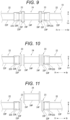
- FIGs. 9 to 11 are side views illustrating the procedure for replacing the sacrificial protective pipe 24.
- the bolt insertion portions 22A and the fixing member 24M are not illustrated.
- Fig. 9 illustrates a state in which the sacrificial protective pipe 24 is connected to the metal pipes 22 via the connecting pipes 23.
- the flanges 23F of the connecting pipes 23 are fastened to the flanges 24F of the sacrificial protective pipe 24, respectively.
- the O-rings 23R are in contact with the inner peripheral surfaces of the sleeves 22S in areas near the sacrificial protective pipe 24.
- the fixing member 24M is removed first, and then the bolts by which the flanges 24F of the sacrificial protective pipe 24 and the flanges 23F of the connecting pipes 23 are fastened are removed.
- the connecting pipes 23 are slid toward the metal pipes 22, respectively, while holding the sacrificial protective pipe 24 (refer to Fig. 10 ), and the sacrificial protective pipe 24 is taken out (refer to Fig. 11 ).
- the O-rings 23R are in contact with the inner peripheral surfaces of the sleeves 22S in areas near the pipe portions 22P. If gaskets or O-rings are secured to the flanges 23F of the connecting pipes 23, the gaskets or O-rings are removed.
- the front and back connecting pipes 23 are slid toward the metal pipes 22, respectively.
- only one of the connecting pipes 23 may be slid.
- the fixing member 24M may be removed after the connecting pipes 23 are slid toward the metal pipes 22. In this case, it is not necessary to hold the sacrificial protective pipe 24.
- the sacrificial protective pipe 24 for replacement is held between the front and back connecting pipes 23 (refer to Fig. 10 ), and the front and back connecting pipes 23 are slid toward the sacrificial protective pipe 24.
- gaskets or O-rings are sandwiched respectively between the flanges 23F of the connecting pipes 23 and the flanges 24F of the sacrificial protective pipe 24.
- the flanges 23F of the connecting pipes 23 and the flanges 24F of the sacrificial protective pipe 24 are fastened by bolts, and the fixing member 24M is mounted.
- the engine 100 includes the sacrificial protective pipe 24 that has been subjected to the sacrificial protective coating process, and the metal pipe 22 connected to at least one of two ends of the sacrificial protective pipe 24.
- maintenance for preventing corrosion of a pipe only requires the replacement of the sacrificial protective pipe 24 alone, and there is no need to replace the metal pipe 22.
- the sacrificial protective pipe 24 has a longer-lasting corrosion prevention effect than an anticorrosive zinc; therefore, the replacement frequency can be reduced.
- a space for installing an anticorrosive zinc is not required; therefore, the pipe can be made compact.
- the engine 100 includes the flow path component (the intercooler side cover 21, the fresh-water cooler side cover 25) connected to one of two ends of the metal pipe 22, the one not being connected to the sacrificial protective pipe 24, and the sacrificial protective material 30 provided to the flow path component.
- the metal pipe 22 is sandwiched between the sacrificial protective pipe 24 and the sacrificial protective material 30; therefore, the corrosion prevention effect is enhanced.
- the replacement frequency of the metal pipe 22 can be reduced.
- the sacrificial protective pipe 24, the metal pipes 22, and the flow path components each including the sacrificial protective material 30 are connected in the order of the flow path component including the sacrificial protective material 30, the metal pipe 22, the sacrificial protective pipe 24, the metal pipe 22, and the flow path component including the sacrificial protective material 30.
- the corrosion prevention effect of the sacrificial protective pipe 24 extends to the upstream side and the downstream side; therefore, the range where the corrosion prevention effect can be further extended.
- the plurality of metal pipes 22 have the same shape; therefore, the cost of the components can be reduced.
- the sacrificial protective pipe 24 is connected to the metal pipe 22 via the connecting pipe 23, and the connecting pipe 23 is slidable along the longitudinal direction of the metal pipe 22 or the sacrificial protective pipe 24. Therefore, even if the sacrificial protective pipe 24 and the metal pipe 22 form a straight flow path, the sacrificial protective pipe 24 can be replaced without removing the metal pipe 22.
- the sacrificial protective coating process is the galvanizing process, and the metal pipe 22 is formed of iron; therefore, corrosion can be prevented with a low-cost material.
- the engine 100 includes the flow path component connected to one of two ends of the metal pipe 22, the one not being connected to the sacrificial protective pipe 24, and the sacrificial protective material 30 provided to the flow path component.
- the sacrificial protective material 30 is formed of zinc or iron; therefore, corrosion can be prevented with a low-cost material.
- seawater appears as an example of a liquid flowing through the metal pipes 22.
- the liquid may be fresh water, tap water, or the like.
- the present invention may be applied to a configuration in which the grounded engine 100 for power generation on land is cooled with fresh water or tap water that is stored in a pit.
- the liquid may be other than water, and may be any substance as long as the substance contains a component that corrodes the metal pipes 22.
- the intercooler 12, the fresh-water cooler 15, and the oil cooler appear as examples of devices that are connected to the cooling pipe 18 in the above embodiment.
- the devices that are connected to the cooling pipe 18 may be any devices as long as the devices cool the engine components with a liquid.
- the intercooler 12 is placed behind, and the fresh-water cooler 15 in front of, the engine 100 appears in the above embodiment.
- the fresh-water cooler 15 may be placed behind, and the intercooler 12 in front of, the engine 100.
- the example in which seawater is supplied from the intercooler 12 to the fresh-water cooler 15 appears in the above embodiment.
- seawater may be supplied from the fresh-water cooler 15 to the intercooler 12.
- the sacrificial protective pipe 24, the metal pipes 22, and the flow path components are placed in the order of the flow path component, the metal pipe 22, the sacrificial protective pipe 24, the metal pipe 22, and the flow path component from the back appears in the above embodiment.
- the flow path component, the metal pipe 22, the sacrificial protective pipe 24, and the flow path component may be placed in this order from the back.
- the flow path component, the sacrificial protective pipe 24, the metal pipe 22, and the flow path component may be placed in this order from the back.
- it is simply required that the metal pipe 22 is connected to at least one of the two ends of the sacrificial protective pipe 24.
- the sacrificial protective material 30 is provided to the flow path component appears in the above embodiment.
- the sacrificial protective material 30 may not be provided to the flow path component.
- the plurality of metal pipes 22 has the same shape appears in the above embodiment.
- the plurality of metal pipes 22 may have different shapes from each other.
- the sacrificial protective coating is hot-dip galvanizing, and the sacrificial protective material 30 is zinc or iron appear in the above embodiment.
- the sacrificial protective coating and the sacrificial protective material 30 are simply required to be substances having a higher ionization tendency than the metal pipe 22.
- the sacrificial protective coating may be hot-dip aluminizing.
- the sacrificial protective material 30 may be formed of aluminum.
- the metal pipe 22 may be made of, for example, stainless steel.
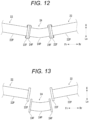
- Fig. 12 is a side view illustrating a cooling pipe 18 according to a modification.
- Fig. 13 is a side view illustrating a state in which a sacrificial protective pipe 24 has been removed from the cooling pipe 18 according to the modification.
- front and back metal pipes 22 are placed in such a manner that axes thereof intersect each other.
- the sacrificial protective pipe 24 is curved in such a manner as to smoothly connect the front and back metal pipes 22.
- the metal pipes 22 each include a flange 22F coupled to one of flanges 24F of the sacrificial protective pipe 24. According to this configuration, even if connecting pipes 23 are not provided, the sacrificial protective pipe 24 can be replaced without removing the metal pipes 22.
Landscapes
- Engineering & Computer Science (AREA)
- Chemical & Material Sciences (AREA)
- Mechanical Engineering (AREA)
- Combustion & Propulsion (AREA)
- General Engineering & Computer Science (AREA)
- Materials Engineering (AREA)
- Metallurgy (AREA)
- Organic Chemistry (AREA)
- Heat-Exchange Devices With Radiators And Conduit Assemblies (AREA)
- Prevention Of Electric Corrosion (AREA)
Abstract
Description
- The present invention relates to an engine.
- When components of a marine engine are cooled with seawater, a cooling pipe through which seawater flows may corrode. Therefore, a technology for preventing corrosion of a cooling pipe has been conventionally studied. For example,
Patent Document 1 describes placing an anticorrosive zinc in an intercooler.Patent Document 2 describes forming an anticorrosive coating inside a cooling pipe. -
- Patent Document 1:
JP-UM-B-60-30420 - Patent Document 2:
JP-A-2019-90362 - An anticorrosive zinc and an anticorrosive coating deteriorate due to use over the long-term. Therefore, periodic replacement is required. However, a bolt-type anticorrosive zinc has a small surface area and therefore reduces in thickness quickly and needs to be replaced frequently. A conceivable way to reduce the frequency of replacement is to use a large anticorrosive zinc. However, in order to do so, it is necessary to increase the diameter of the pipe. Hence, there are problems such as an increase in the cost of the components and an increase in the degree of difficulty in the placement of the components. On the other hand, when a cooling pipe in which an anticorrosive coating is formed is used, there is a problem that the replacement work is more extensive than that of the anticorrosive zinc.
- Considering the above circumstances, an object of the present invention is to provide an engine that can reduce the burden of maintenance for preventing corrosion of a pipe.
- In order to solve the above problem, an engine according to the present invention includes: a sacrificial protective pipe subjected to a sacrificial protective coating process; and a metal pipe connected to at least one of two ends of the sacrificial protective pipe.
- The engine may include: a flow path component connected to one of two ends of the metal pipe, the one not being connected to the sacrificial protective pipe; and a sacrificial protective material provided to the flow path component.
- The sacrificial protective pipe, the metal pipes, and the flow path components each including the sacrificial protective material may be connected in an order of the flow path component including the sacrificial protective material, the metal pipe, the sacrificial protective pipe, the metal pipe, and the flow path component including the sacrificial protective material.
- The plurality of metal pipes may have a same shape.
- The sacrificial protective pipe may be connected to the metal pipe via a connecting pipe, and the connecting pipe may be slidable along a longitudinal direction of the metal pipe or the sacrificial protective pipe.
- The sacrificial protective coating process may be a galvanizing process, and the metal pipe may be formed of iron.
- The engine may include: a flow path component connected to one of two ends of the metal pipe, the one not being connected to the sacrificial protective pipe; and a sacrificial protective material provided to the flow path component, in which the sacrificial protective material may be formed of zinc or iron.
- According to the present invention, it is possible to reduce the burden of maintenance for preventing corrosion of a pipe.
-
-
Fig. 1 is a perspective view illustrating an engine according to an embodiment of the present invention; -
Fig. 2 is a perspective view illustrating air intake and exhaust paths according to the embodiment of the present invention; -
Fig. 3 is a perspective view illustrating the air intake and exhaust paths according to the embodiment of the present invention; -
Fig. 4 is a perspective view illustrating a cooling pipe according to the embodiment of the present invention; -
Fig. 5 is a perspective view illustrating an intercooler side cover according to the embodiment of the present invention; -
Fig. 6 is a perspective view illustrating a fresh-water cooler side cover according to the embodiment of the present invention; -
Fig. 7 is a perspective view illustrating the main elements of the cooling pipe according to the embodiment of the present invention; -
Fig. 8 is an exploded view illustrating the main elements of the cooling pipe according to the embodiment of the present invention; -
Fig. 9 is a side view illustrating the main elements of the cooling pipe according to the embodiment of the present invention; -
Fig. 10 is a side view illustrating a procedure for replacing a sacrificial protective pipe according to the embodiment of the present invention; -
Fig. 11 is a side view illustrating the procedure for replacing the sacrificial protective pipe according to the embodiment of the present invention; -
Fig. 12 is a side view illustrating a sacrificial protective pipe according to a modification of the embodiment of the present invention; and -
Fig. 13 is a side view illustrating a state where the sacrificial protective pipe according to the modification of the embodiment of the present invention has been removed. - An
engine 100 according to an embodiment of the present invention is described hereinafter with reference to the drawings. - First, the entire configuration of the
engine 100 is described.Fig. 1 is a perspective view illustrating theengine 100. In the drawings, U, Lo, L, R, Fr, and Rr denote up, down, left, right, front, and back, respectively. An example in which acylinder head 1 is provided on top of acylinder block 2 appears in the embodiment. However, theengine 100 may be used in any attitude. Moreover, an inline-six diesel engine appears, as an example of an application target of the present invention, in the embodiment. However, the present invention is suitable for all reciprocating engines with a plurality of cylinders. - The
engine 100 includes thecylinder head 1, thecylinder block 2, and anoil pan 5. In thecylinder head 1, six component groups (not illustrated) including an air intake path, an exhaust path, an intake valve, an exhaust valve, and an injector are placed in series along a front-and-back direction. Thecylinder block 2 includes: acylinder row 3 in which six cylinders (not illustrated) housing a piston and a connecting rod are placed in series along the front-and-back direction; and acrankcase 4 housing a crankshaft (not illustrated). Theoil pan 5 stores lubricating oil. - Next, air intake and exhaust paths are described.
Figs. 2 and3 are perspective views illustrating the air intake and exhaust paths. The air intake and exhaust paths include aturbocharger 11, anintercooler 12, anintake manifold 13, thecylinder head 1, and anexhaust manifold 14. - The
turbocharger 11 includes aturbine 11T and acompressor 11C. Thecompressor 11C is connected to theintercooler 12. Theintake manifold 13 includes amain body portion 13B, an air intake inlet port 13i, and sixair intake passages 13E. The air intake inlet port 13i is connected to theintercooler 12. The sixair intake passages 13E are connected to the air intake path (not illustrated) of thecylinder head 1. Theexhaust manifold 14 includes acollector 14C, sixexhaust inlet ports 14i, and anexhaust outlet port 14E. The sixexhaust inlet ports 14i are connected to the exhaust path (not illustrated) of thecylinder head 1. Theexhaust outlet port 14E is connected to theturbine 11T. - Exhaust gases from the cylinders are supplied to the
turbine 11T through the exhaust path of thecylinder head 1 and theexhaust manifold 14. Theturbine 11T rotates by exhaust energy. Thecompressor 11C rotates together with theturbine 11T to take in and compress air. The compressed air is sent to theintercooler 12. Theintercooler 12 cools the compressed air and sends the compressed air to theintake manifold 13. Theintake manifold 13 has a function of a surge tank that equalizes the density, intake volume, and stream of the compressed air supplied to each cylinder, and supplies the compressed air to the air intake path of thecylinder head 1 through theair intake passages 13E. - Next, an outline of a cooling
pipe 18 is described.Fig. 4 is a perspective view illustrating the coolingpipe 18. Afeed water pipe 16 including apump 17 is connected to theintercooler 12. Theintercooler 12 cools intake air with seawater sucked up by thepump 17. A fresh-water cooler 15 is connected to theintercooler 12 via the coolingpipe 18. The seawater used to cool the intake air in theintercooler 12 is supplied to the fresh-water cooler 15 through the coolingpipe 18. The fresh-water cooler 15 cools coolant circulating in a water jacket (not illustrated) provided to theengine 100, with the seawater supplied from theintercooler 12. The seawater used to cool the coolant in the fresh-water cooler 15 is used to cool the lubricating oil in an oil cooler (not illustrated) and then discharged to the outside of the ship. - Next, the cooling
pipe 18 is described in detail.Fig. 5 is a perspective view illustrating anintercooler side cover 21.Fig. 6 is a perspective view illustrating a fresh-watercooler side cover 25.Fig. 7 is a perspective view illustrating the main elements of the coolingpipe 18.Fig. 8 is an exploded view illustrating the main elements of the coolingpipe 18.Fig. 9 is a side view illustrating the main elements of the coolingpipe 18. InFig. 7 , connectingpipes 23 andmetal pipes 22 are provided in front of and behind a sacrificialprotective pipe 24. However, inFig. 8 , only the sacrificialprotective pipe 24, and the connectingpipe 23 and themetal pipe 22 that are in front of the sacrificialprotective pipe 24 are illustrated. - The
engine 100 includes the sacrificialprotective pipe 24 that has been subjected to a sacrificial protective coating process, and themetal pipe 22 connected to at least one of two ends of the sacrificialprotective pipe 24. - The intercooler 12 (refer to
Figs. 4 and5 ) includes anintercooler housing 20 and the intercooler side cover 21 (an example of a flow path component) that blocks an opening (not illustrated) provided in the left side of theintercooler housing 20. - The
intercooler housing 20 includes an air intake inlet port 20i and an airintake outlet port 20E. The air intake inlet port 20i is provided in a portion on the right side of the bottom of theintercooler housing 20. The airintake outlet port 20E is provided in a portion that is further to the left than the center of theintercooler housing 20 in the left-and-right direction. The airintake outlet port 20E opens to the front and upward. - The intercooler side cover 21 is substantially circular and recessed leftward. A space inside the intercooler side cover 21 is divided by a
partition wall 21W into a firstauxiliary chamber 211 on the bottom and a secondauxiliary chamber 212 on the top. The firstauxiliary chamber 211 is provided with aliquid inlet port 21i penetrating in the left-and-right direction. Theliquid inlet port 21i is connected to thefeed water pipe 16. The secondauxiliary chamber 212 is provided with aliquid outlet port 21E penetrating in the front-and-back direction. Theliquid outlet port 21E is connected to the back end of the coolingpipe 18. The firstauxiliary chamber 211 and the secondauxiliary chamber 212 are each provided with an insertion port (not illustrated) penetrating from the inside through to the outside. A female thread is formed in each of the insertion ports. A bolt-shaped sacrificialprotective material 30 with a male thread is mounted in the each of the insertion ports. The sacrificialprotective material 30 protrudes from the inner surface of each of the firstauxiliary chamber 211 and the secondauxiliary chamber 212. The sacrificialprotective material 30 is formed of zinc or iron. Zinc that contains, as a main raw material, high-purity zinc metal with a purity equal to or greater than 99.99% is used. Iron that is pure iron with a purity equal to or greater than 99.90% is used. - The fresh-water cooler 15 (refer to
Figs. 4 and6 ) includes a fresh-water cooler housing 26 and the fresh-water cooler side cover 25 (an example of the flow path component) that blocks an opening (not illustrated) provided in the left side of the fresh-water cooler housing 26. The fresh-water cooler side cover 25 is substantially circular and recessed leftward. A space inside the fresh-water cooler side cover 25 is divided by apartition wall 25W into a firstauxiliary chamber 251 on the top and a secondauxiliary chamber 252 on the bottom. The firstauxiliary chamber 251 is provided with a liquid inlet port 25i penetrating in the front-and-back direction. The liquid inlet port 25i is connected to the front end of the coolingpipe 18. The firstauxiliary chamber 251 and the secondauxiliary chamber 252 are each provided with an insertion port (not illustrated) penetrating from the inside through to the outside. A female thread is formed in each of the insertion ports. The above-mentioned sacrificialprotective material 30 is mounted in the each of the insertion ports. The sacrificialprotective material 30 protrudes from the inner surface of each of the firstauxiliary chamber 251 and the secondauxiliary chamber 252. - The cooling pipe 18 (refer to
Figs. 4 and7 to 9 ) includes themetal pipes 22 and the sacrificialprotective pipe 24. Seawater flows from theintercooler 12 to the fresh-water cooler 15 through the coolingpipe 18. Themetal pipes 22, the sacrificialprotective pipe 24, theintercooler side cover 21, and the fresh-water cooler side cover 25 are placed in the order of theintercooler side cover 21, themetal pipe 22, the sacrificialprotective pipe 24, themetal pipe 22, and the fresh-water cooler side cover 25 from the back. - The
metal pipes 22 are formed of iron. Sacrificial protective coatings are not formed on the inner peripheral surfaces of themetal pipes 22. Themetal pipes 22 in front of and behind the sacrificialprotective pipe 24 have the same shape.
Specifically, themetal pipes 22 are at least configured in such a manner as to have a common shape at two ends of each of themetal pipes 22 and a common length and to be interchangeable as a cooling water pipe. As long as being interchangeable as a cooling water pipe, themetal pipes 22 are regarded as having the same shape even if the shape and placement of a boss formed on the pipe surface are different. The each of themetal pipes 22 includes apipe portion 22P, aflange 22F provided at one end of thepipe portion 22P in the front-and-back direction, and asleeve 22S provided at the other end of thepipe portion 22P. The inner diameter of thesleeves 22S is greater than the inner diameter of thepipe portions 22P. Theflange 22F of themetal pipe 22 near theintercooler 12 is fastened to theliquid outlet port 21E of the intercooler side cover 21 by a bolt via a gasket or an O-ring (neither illustrated). Theflange 22F of themetal pipe 22 near the fresh-water cooler 15 is fastened to the liquid inlet port 25i of the fresh-water cooler side cover 25 by a bolt via a gasket or an O-ring (neither illustrated). - A
bolt insertion portion 22A is provided in the vicinity of an end of thepipe portion 22P of the each of themetal pipes 22, the end being near therespective sleeve 22S (refer toFigs. 7 and 8 ). Each of thebolt insertion portions 22A is a portion expanding upward and downward from the outer peripheral surface of therespective pipe portion 22P. The each of thebolt insertion portions 22A is provided with a bolt hole penetrating in the left-and-right direction. A female thread is provided in the left side surface of themain body portion 13B of theintake manifold 13, in a position corresponding to each of the bolt holes of thebolt insertion portions 22A (not illustrated). Themetal pipes 22 are fastened to theintake manifold 13 by bolts to be fixed to the intake manifold 13 (refer toFig. 2 ). - The sacrificial
protective pipe 24 is formed of iron. The sacrificialprotective pipe 24 includes apipe portion 24P, and aflange 24F provided at each end of thepipe portion 24P. The inner surface of the sacrificialprotective pipe 24 has been subjected to a galvanizing process such as hot-dip galvanizing or electrogalvanizing. Zinc that contains, as a main raw material, high-purity zinc metal with a purity equal to or greater than 99.99% is used. - The
metal pipes 22 and the sacrificialprotective pipe 24 are connected together by the connectingpipes 23. Each of the connectingpipes 23 includes apipe portion 23P, and aflange 23F provided at one end of thepipe portion 23P in the front-and-back direction. Agroove 23G in which an O-ring 23R (refer toFig. 9 ) fits along the circumferential direction is provided in the outer peripheral surface at the other end of each of thepipe portions 23P. When the other ends of the connectingpipes 23 are inserted into thesleeves 22S of themetal pipes 22, the O-rings 23R are pressed against the inner peripheral surfaces of thesleeves 22S, thereby preventing the leakage of seawater. The connectingpipes 23 are slidable in the front-and-back direction along the inner peripheral surfaces of thesleeves 22S. Theflanges 23F of the connectingpipes 23 are fastened to theflanges 24F of the sacrificialprotective pipe 24 by bolts via gaskets or O-rings (neither illustrated). - The sacrificial
protective pipe 24 is fixed to theintake manifold 13 by a fixingmember 24M (refer toFigs. 2 and7 ). The fixingmember 24M is, for example, a metal band. In this example, the fixingmember 24M includes two bands coupled by a bolt and a nut, but may include one band. The fixingmember 24M is wrapped around thepipe portion 24P of the sacrificialprotective pipe 24. Each end of the fixingmember 24M in the longitudinal direction is bent along the left side surface of themain body portion 13B of theintake manifold 13, and includes a bolt hole penetrating in the left-and-right direction. A female thread is provided in the left side surface of themain body portion 13B of theintake manifold 13, in each of positions corresponding to the bolt holes of the fixingmember 24M (not illustrated). The sacrificialprotective pipe 24 is fastened to theintake manifold 13 by a bolt to be fixed to theintake manifold 13. - The seawater that has flown from the
feed water pipe 16 into the firstauxiliary chamber 211 through theliquid inlet port 21i of the intercooler side cover 21 cools the compressed air while flowing along a flow path (not illustrated) in theintercooler housing 20, and flows from the secondauxiliary chamber 212 into the coolingpipe 18 through theliquid outlet port 21E. The seawater that has flown from the coolingpipe 18 into the firstauxiliary chamber 251 through the liquid inlet port 25i of the fresh-water cooler side cover 25 flows into the secondauxiliary chamber 252 over thepartition wall 25W, cools the coolant while flowing along a flow path (not illustrated) in the fresh-water cooler 15, and is discharged to the outside of the ship through aliquid outlet port 26E and the oil cooler (not illustrated). - Next, a procedure for replacing the sacrificial
protective pipe 24 is described (refer toFigs. 9 to 11). Figs. 10 and 11 are side views illustrating the procedure for replacing the sacrificialprotective pipe 24. InFigs. 9 to 11 , thebolt insertion portions 22A and the fixingmember 24M are not illustrated. -
Fig. 9 illustrates a state in which the sacrificialprotective pipe 24 is connected to themetal pipes 22 via the connectingpipes 23. Theflanges 23F of the connectingpipes 23 are fastened to theflanges 24F of the sacrificialprotective pipe 24, respectively. The O-rings 23R are in contact with the inner peripheral surfaces of thesleeves 22S in areas near the sacrificialprotective pipe 24. - When the sacrificial
protective pipe 24 is replaced, the fixingmember 24M is removed first, and then the bolts by which theflanges 24F of the sacrificialprotective pipe 24 and theflanges 23F of the connectingpipes 23 are fastened are removed. - Next, the connecting
pipes 23 are slid toward themetal pipes 22, respectively, while holding the sacrificial protective pipe 24 (refer toFig. 10 ), and the sacrificialprotective pipe 24 is taken out (refer toFig. 11 ). The O-rings 23R are in contact with the inner peripheral surfaces of thesleeves 22S in areas near thepipe portions 22P. If gaskets or O-rings are secured to theflanges 23F of the connectingpipes 23, the gaskets or O-rings are removed. In this example, the front and back connectingpipes 23 are slid toward themetal pipes 22, respectively. However, only one of the connectingpipes 23 may be slid. Moreover, the fixingmember 24M may be removed after the connectingpipes 23 are slid toward themetal pipes 22. In this case, it is not necessary to hold the sacrificialprotective pipe 24. - Next, the sacrificial
protective pipe 24 for replacement is held between the front and back connecting pipes 23 (refer toFig. 10 ), and the front and back connectingpipes 23 are slid toward the sacrificialprotective pipe 24. At this point in time, gaskets or O-rings (neither illustrated) are sandwiched respectively between theflanges 23F of the connectingpipes 23 and theflanges 24F of the sacrificialprotective pipe 24. Moreover, it is desirable to adjust the positions of the connectingpipes 23 in such a manner that the sacrificialprotective pipe 24 is equidistant from the front andback metal pipes 22. Lastly, theflanges 23F of the connectingpipes 23 and theflanges 24F of the sacrificialprotective pipe 24 are fastened by bolts, and the fixingmember 24M is mounted. - The
engine 100 according to the embodiment described above includes the sacrificialprotective pipe 24 that has been subjected to the sacrificial protective coating process, and themetal pipe 22 connected to at least one of two ends of the sacrificialprotective pipe 24. According to this configuration, maintenance for preventing corrosion of a pipe only requires the replacement of the sacrificialprotective pipe 24 alone, and there is no need to replace themetal pipe 22. Moreover, the sacrificialprotective pipe 24 has a longer-lasting corrosion prevention effect than an anticorrosive zinc; therefore, the replacement frequency can be reduced. Hence, it is possible to reduce the burden of maintenance for preventing corrosion of a pipe. Moreover, a space for installing an anticorrosive zinc is not required; therefore, the pipe can be made compact. - Moreover, the
engine 100 according to the embodiment includes the flow path component (theintercooler side cover 21, the fresh-water cooler side cover 25) connected to one of two ends of themetal pipe 22, the one not being connected to the sacrificialprotective pipe 24, and the sacrificialprotective material 30 provided to the flow path component. According to this configuration, themetal pipe 22 is sandwiched between the sacrificialprotective pipe 24 and the sacrificialprotective material 30; therefore, the corrosion prevention effect is enhanced. Hence, the replacement frequency of themetal pipe 22 can be reduced. - Moreover, in the
engine 100 according to the embodiment, the sacrificialprotective pipe 24, themetal pipes 22, and the flow path components each including the sacrificialprotective material 30 are connected in the order of the flow path component including the sacrificialprotective material 30, themetal pipe 22, the sacrificialprotective pipe 24, themetal pipe 22, and the flow path component including the sacrificialprotective material 30. According to this configuration, the corrosion prevention effect of the sacrificialprotective pipe 24 extends to the upstream side and the downstream side; therefore, the range where the corrosion prevention effect can be further extended. - Moreover, in the
engine 100 according to the embodiment, the plurality ofmetal pipes 22 have the same shape; therefore, the cost of the components can be reduced. - Moreover, in the
engine 100 according to the embodiment, the sacrificialprotective pipe 24 is connected to themetal pipe 22 via the connectingpipe 23, and the connectingpipe 23 is slidable along the longitudinal direction of themetal pipe 22 or the sacrificialprotective pipe 24. Therefore, even if the sacrificialprotective pipe 24 and themetal pipe 22 form a straight flow path, the sacrificialprotective pipe 24 can be replaced without removing themetal pipe 22. - Moreover, in the
engine 100 according to the embodiment, the sacrificial protective coating process is the galvanizing process, and themetal pipe 22 is formed of iron; therefore, corrosion can be prevented with a low-cost material. - Moreover, the
engine 100 according to the embodiment includes the flow path component connected to one of two ends of themetal pipe 22, the one not being connected to the sacrificialprotective pipe 24, and the sacrificialprotective material 30 provided to the flow path component. The sacrificialprotective material 30 is formed of zinc or iron; therefore, corrosion can be prevented with a low-cost material. - The above embodiment may be modified as follows:
- In the above embodiment, seawater appears as an example of a liquid flowing through the
metal pipes 22. However, the liquid may be fresh water, tap water, or the like. For example, the present invention may be applied to a configuration in which the groundedengine 100 for power generation on land is cooled with fresh water or tap water that is stored in a pit. Moreover, the liquid may be other than water, and may be any substance as long as the substance contains a component that corrodes themetal pipes 22. - The
intercooler 12, the fresh-water cooler 15, and the oil cooler appear as examples of devices that are connected to the coolingpipe 18 in the above embodiment. However, the devices that are connected to the coolingpipe 18 may be any devices as long as the devices cool the engine components with a liquid. - The example in which the
intercooler 12 is placed behind, and the fresh-water cooler 15 in front of, theengine 100 appears in the above embodiment. However, the fresh-water cooler 15 may be placed behind, and theintercooler 12 in front of, theengine 100. Moreover, the example in which seawater is supplied from theintercooler 12 to the fresh-water cooler 15 appears in the above embodiment. However, seawater may be supplied from the fresh-water cooler 15 to theintercooler 12. - The example in which the sacrificial
protective pipe 24, themetal pipes 22, and the flow path components are placed in the order of the flow path component, themetal pipe 22, the sacrificialprotective pipe 24, themetal pipe 22, and the flow path component from the back appears in the above embodiment. However, the flow path component, themetal pipe 22, the sacrificialprotective pipe 24, and the flow path component may be placed in this order from the back. Moreover, the flow path component, the sacrificialprotective pipe 24, themetal pipe 22, and the flow path component may be placed in this order from the back. In short, it is simply required that themetal pipe 22 is connected to at least one of the two ends of the sacrificialprotective pipe 24. - The example in which the sacrificial
protective material 30 is provided to the flow path component appears in the above embodiment. However, the sacrificialprotective material 30 may not be provided to the flow path component. - The example in which the plurality of
metal pipes 22 has the same shape appears in the above embodiment. However, the plurality ofmetal pipes 22 may have different shapes from each other. - The examples in which the sacrificial protective coating is hot-dip galvanizing, and the sacrificial
protective material 30 is zinc or iron appear in the above embodiment. However, the sacrificial protective coating and the sacrificialprotective material 30 are simply required to be substances having a higher ionization tendency than themetal pipe 22. For example, the sacrificial protective coating may be hot-dip aluminizing. Moreover, the sacrificialprotective material 30 may be formed of aluminum. Moreover, themetal pipe 22 may be made of, for example, stainless steel. -
Fig. 12 is a side view illustrating a coolingpipe 18 according to a modification.Fig. 13 is a side view illustrating a state in which a sacrificialprotective pipe 24 has been removed from the coolingpipe 18 according to the modification. In this example, front andback metal pipes 22 are placed in such a manner that axes thereof intersect each other. The sacrificialprotective pipe 24 is curved in such a manner as to smoothly connect the front andback metal pipes 22. Themetal pipes 22 each include aflange 22F coupled to one offlanges 24F of the sacrificialprotective pipe 24. According to this configuration, even if connectingpipes 23 are not provided, the sacrificialprotective pipe 24 can be replaced without removing themetal pipes 22. -
- 100
- Engine
- 21
- Intercooler side cover (flow path component)
- 22
- Metal pipe
- 23
- Connecting pipe
- 24
- Sacrificial protective pipe
- 25
- Fresh-water cooler side cover (flow path component)
- 30
- Sacrificial protective material
Claims (7)
- An engine comprising:a sacrificial protective pipe subjected to a sacrificial protective coating process; anda metal pipe connected to at least one of two ends of the sacrificial protective pipe.
- The engine according to claim 1, comprising:a flow path component connected to one of two ends of the metal pipe, the one not being connected to the sacrificial protective pipe; anda sacrificial protective material provided to the flow path component.
- The engine according to claim 2, wherein the sacrificial protective pipe, the metal pipes, and the flow path components each including the sacrificial protective material are connected in an order of the flow path component including the sacrificial protective material, the metal pipe, the sacrificial protective pipe, the metal pipe, and the flow path component including the sacrificial protective material.
- The engine according to any one of claims 1 to 3, wherein the plurality of metal pipes has a same shape.
- The engine according to any one of claims 1 to 4, whereinthe sacrificial protective pipe is connected to the metal pipe via a connecting pipe, andthe connecting pipe is slidable along a longitudinal direction of the metal pipe or the sacrificial protective pipe.
- The engine according to any one of claims 1 to 5, wherein
the sacrificial protective coating process is a galvanizing process, and the metal pipe is formed of iron. - The engine according to any one of claims 1 to 6, comprising:a flow path component connected to one of two ends of the metal pipe, the one not being connected to the sacrificial protective pipe; anda sacrificial protective material provided to the flow path component, whereinthe sacrificial protective material is formed of zinc or iron.
Applications Claiming Priority (1)
| Application Number | Priority Date | Filing Date | Title |
|---|---|---|---|
| JP2022023514A JP7633957B2 (en) | 2022-02-18 | 2022-02-18 | engine |
Publications (1)
| Publication Number | Publication Date |
|---|---|
| EP4230851A1 true EP4230851A1 (en) | 2023-08-23 |
Family
ID=85222233
Family Applications (1)
| Application Number | Title | Priority Date | Filing Date |
|---|---|---|---|
| EP23155715.8A Pending EP4230851A1 (en) | 2022-02-18 | 2023-02-09 | Engine |
Country Status (5)
| Country | Link |
|---|---|
| US (1) | US12055086B2 (en) |
| EP (1) | EP4230851A1 (en) |
| JP (1) | JP7633957B2 (en) |
| KR (1) | KR20230124469A (en) |
| CN (1) | CN116624259A (en) |
Citations (6)
| Publication number | Priority date | Publication date | Assignee | Title |
|---|---|---|---|---|
| JPS5332247U (en) * | 1976-08-25 | 1978-03-20 | ||
| JPS6030420B2 (en) | 1981-11-24 | 1985-07-16 | 東京電力株式会社 | Heat pump floor heating system |
| US4562697A (en) * | 1984-12-10 | 1986-01-07 | Merlin Marine Engine Corp. | Intercooler for turbocharged internal combustion engine |
| JP2019090362A (en) | 2017-11-14 | 2019-06-13 | 株式会社豊田自動織機 | Rustproof effect detection device |
| CN110425030A (en) * | 2019-09-11 | 2019-11-08 | 浙江银轮机械股份有限公司 | Intercooler |
| KR102215070B1 (en) * | 2019-08-12 | 2021-02-09 | 오병래 | cooling apparatus of an engine for ship |
Family Cites Families (15)
| Publication number | Priority date | Publication date | Assignee | Title |
|---|---|---|---|---|
| JPS6030420Y2 (en) | 1981-02-07 | 1985-09-12 | 株式会社クボタ | Intercooler in internal combustion engine |
| JPS59127819U (en) * | 1983-02-17 | 1984-08-28 | 新キャタピラ−三菱株式会社 | Direct injection engine liner pitting prevention device |
| JPS6030420A (en) | 1983-07-29 | 1985-02-16 | Mazda Motor Corp | Stratiform charging engine |
| WO2000006934A1 (en) * | 1998-07-29 | 2000-02-10 | Aisan Kogyo Kabushiki Kaisha | Fluid supply pipe |
| JP2003183855A (en) | 2001-10-05 | 2003-07-03 | Nippon Steel Corp | Freshwater piping and piping components |
| JP4055004B2 (en) * | 2002-09-30 | 2008-03-05 | 東海ゴム工業株式会社 | Detent for connector |
| JP5225662B2 (en) * | 2007-11-21 | 2013-07-03 | 三桜工業株式会社 | Steel pipe for vehicle piping |
| WO2011070353A2 (en) * | 2009-12-07 | 2011-06-16 | Smart Pipe Company, Lp | Systems and methods for making pipe, and method of installing the pipe in a pipeline |
| US8464424B2 (en) * | 2010-11-01 | 2013-06-18 | Hans Martin Christensen | Automotive engine cooling pipe apparatus and method of use |
| US20140116668A1 (en) * | 2012-10-31 | 2014-05-01 | GM Global Technology Operations LLC | Cooler pipe and method of forming |
| US9719680B2 (en) * | 2014-05-02 | 2017-08-01 | Todd Staller | Portable, free-standing exhaust system |
| JP6635022B2 (en) * | 2016-12-26 | 2020-01-22 | 株式会社デンソー | Intercooler and method of manufacturing the intercooler |
| SE540593C2 (en) * | 2016-12-29 | 2018-10-02 | Pure Bio Synergy Sweden Ab | Electric discharge device and method for treatment of fluids |
| US10221490B2 (en) | 2017-07-05 | 2019-03-05 | Packless Industries | Visual electrolytic corrosion indication and prevention apparatus |
| KR102463205B1 (en) * | 2017-12-20 | 2022-11-03 | 현대자동차 주식회사 | Egr cooler for vehicle |
-
2022
- 2022-02-18 JP JP2022023514A patent/JP7633957B2/en active Active
- 2022-12-26 KR KR1020220184318A patent/KR20230124469A/en active Pending
-
2023
- 2023-01-05 CN CN202310014324.XA patent/CN116624259A/en active Pending
- 2023-02-09 EP EP23155715.8A patent/EP4230851A1/en active Pending
- 2023-02-17 US US18/111,432 patent/US12055086B2/en active Active
Patent Citations (6)
| Publication number | Priority date | Publication date | Assignee | Title |
|---|---|---|---|---|
| JPS5332247U (en) * | 1976-08-25 | 1978-03-20 | ||
| JPS6030420B2 (en) | 1981-11-24 | 1985-07-16 | 東京電力株式会社 | Heat pump floor heating system |
| US4562697A (en) * | 1984-12-10 | 1986-01-07 | Merlin Marine Engine Corp. | Intercooler for turbocharged internal combustion engine |
| JP2019090362A (en) | 2017-11-14 | 2019-06-13 | 株式会社豊田自動織機 | Rustproof effect detection device |
| KR102215070B1 (en) * | 2019-08-12 | 2021-02-09 | 오병래 | cooling apparatus of an engine for ship |
| CN110425030A (en) * | 2019-09-11 | 2019-11-08 | 浙江银轮机械股份有限公司 | Intercooler |
Also Published As
| Publication number | Publication date |
|---|---|
| JP7633957B2 (en) | 2025-02-20 |
| US20230265779A1 (en) | 2023-08-24 |
| KR20230124469A (en) | 2023-08-25 |
| CN116624259A (en) | 2023-08-22 |
| US12055086B2 (en) | 2024-08-06 |
| JP2023120570A (en) | 2023-08-30 |
Similar Documents
| Publication | Publication Date | Title |
|---|---|---|
| US20110252775A1 (en) | Exhaust flow insulator for an exhaust system device | |
| CN102966425A (en) | Turbocharger | |
| US6805108B2 (en) | Heat exchanger for a supercharger | |
| US7389759B2 (en) | Internal-combustion engine | |
| US20100313860A1 (en) | Apparatus for removal of oil from positive crankcase ventilation system | |
| AT511648B1 (en) | Internal combustion engine | |
| JP4580366B2 (en) | Intercooler for internal combustion engine | |
| CA2576213A1 (en) | Individual cylinder assemblies and modular cylinder carrier | |
| US10858974B1 (en) | Lubricant coolers for marine engines | |
| US12055086B2 (en) | Engine | |
| EP4230852A1 (en) | Engine | |
| US4104999A (en) | After-cooler accessory unit for internal combustion engine having a carburetor | |
| EP2511511B1 (en) | Charge air guide element and internal combustion engine with a charge air guide element | |
| US12366186B2 (en) | Lubricant manifold for internal combustion engine | |
| EP2836691B1 (en) | Charge air guide element for internal combustion engine | |
| EP0680552B1 (en) | Air inlet aftercooler mounting and sealing system | |
| US6363717B1 (en) | Exhaust gas duct cooled with water | |
| EP2511510B1 (en) | Engine block and internal combustion engine with an engine block | |
| US11988119B1 (en) | Internal combustion engine with ventilation system for crankcase dilution | |
| GB2554922B (en) | Exhaust duct for internal combustion engine | |
| EP2511509A1 (en) | Mixing pipe and internal combustion engine with a mixing pipe | |
| RU170557U1 (en) | Engine for diesel generator sets | |
| EP4196668A1 (en) | Head assembly with rotary valves for an internal combustion engine |
Legal Events
| Date | Code | Title | Description |
|---|---|---|---|
| PUAI | Public reference made under article 153(3) epc to a published international application that has entered the european phase |
Free format text: ORIGINAL CODE: 0009012 |
|
| STAA | Information on the status of an ep patent application or granted ep patent |
Free format text: STATUS: THE APPLICATION HAS BEEN PUBLISHED |
|
| AK | Designated contracting states |
Kind code of ref document: A1 Designated state(s): AL AT BE BG CH CY CZ DE DK EE ES FI FR GB GR HR HU IE IS IT LI LT LU LV MC ME MK MT NL NO PL PT RO RS SE SI SK SM TR |
|
| STAA | Information on the status of an ep patent application or granted ep patent |
Free format text: STATUS: REQUEST FOR EXAMINATION WAS MADE |
|
| 17P | Request for examination filed |
Effective date: 20240221 |
|
| STAA | Information on the status of an ep patent application or granted ep patent |
Free format text: STATUS: EXAMINATION IS IN PROGRESS |
|
| 17Q | First examination report despatched |
Effective date: 20250103 |