EP4230833A1 - Curtain - Google Patents
Curtain Download PDFInfo
- Publication number
- EP4230833A1 EP4230833A1 EP22830356.6A EP22830356A EP4230833A1 EP 4230833 A1 EP4230833 A1 EP 4230833A1 EP 22830356 A EP22830356 A EP 22830356A EP 4230833 A1 EP4230833 A1 EP 4230833A1
- Authority
- EP
- European Patent Office
- Prior art keywords
- clamping strip
- strip
- clamped
- base
- clamping
- Prior art date
- Legal status (The legal status is an assumption and is not a legal conclusion. Google has not performed a legal analysis and makes no representation as to the accuracy of the status listed.)
- Withdrawn
Links
Images


Classifications
-
- E—FIXED CONSTRUCTIONS
- E06—DOORS, WINDOWS, SHUTTERS, OR ROLLER BLINDS IN GENERAL; LADDERS
- E06B—FIXED OR MOVABLE CLOSURES FOR OPENINGS IN BUILDINGS, VEHICLES, FENCES OR LIKE ENCLOSURES IN GENERAL, e.g. DOORS, WINDOWS, BLINDS, GATES
- E06B9/00—Screening or protective devices for wall or similar openings, with or without operating or securing mechanisms; Closures of similar construction
- E06B9/24—Screens or other constructions affording protection against light, especially against sunshine; Similar screens for privacy or appearance; Slat blinds
- E06B9/26—Lamellar or like blinds, e.g. venetian blinds
- E06B9/28—Lamellar or like blinds, e.g. venetian blinds with horizontal lamellae, e.g. non-liftable
- E06B9/30—Lamellar or like blinds, e.g. venetian blinds with horizontal lamellae, e.g. non-liftable liftable
- E06B9/32—Operating, guiding, or securing devices therefor
- E06B9/322—Details of operating devices, e.g. pulleys, brakes, spring drums, drives
-
- E—FIXED CONSTRUCTIONS
- E06—DOORS, WINDOWS, SHUTTERS, OR ROLLER BLINDS IN GENERAL; LADDERS
- E06B—FIXED OR MOVABLE CLOSURES FOR OPENINGS IN BUILDINGS, VEHICLES, FENCES OR LIKE ENCLOSURES IN GENERAL, e.g. DOORS, WINDOWS, BLINDS, GATES
- E06B9/00—Screening or protective devices for wall or similar openings, with or without operating or securing mechanisms; Closures of similar construction
- E06B9/24—Screens or other constructions affording protection against light, especially against sunshine; Similar screens for privacy or appearance; Slat blinds
- E06B9/26—Lamellar or like blinds, e.g. venetian blinds
- E06B9/262—Lamellar or like blinds, e.g. venetian blinds with flexibly-interconnected horizontal or vertical strips; Concertina blinds, i.e. upwardly folding flexible screens
-
- H—ELECTRICITY
- H01—ELECTRIC ELEMENTS
- H01M—PROCESSES OR MEANS, e.g. BATTERIES, FOR THE DIRECT CONVERSION OF CHEMICAL ENERGY INTO ELECTRICAL ENERGY
- H01M50/00—Constructional details or processes of manufacture of the non-active parts of electrochemical cells other than fuel cells, e.g. hybrid cells
- H01M50/20—Mountings; Secondary casings or frames; Racks, modules or packs; Suspension devices; Shock absorbers; Transport or carrying devices; Holders
- H01M50/244—Secondary casings; Racks; Suspension devices; Carrying devices; Holders characterised by their mounting method
-
- H—ELECTRICITY
- H01—ELECTRIC ELEMENTS
- H01M—PROCESSES OR MEANS, e.g. BATTERIES, FOR THE DIRECT CONVERSION OF CHEMICAL ENERGY INTO ELECTRICAL ENERGY
- H01M50/00—Constructional details or processes of manufacture of the non-active parts of electrochemical cells other than fuel cells, e.g. hybrid cells
- H01M50/20—Mountings; Secondary casings or frames; Racks, modules or packs; Suspension devices; Shock absorbers; Transport or carrying devices; Holders
- H01M50/251—Mountings; Secondary casings or frames; Racks, modules or packs; Suspension devices; Shock absorbers; Transport or carrying devices; Holders specially adapted for stationary devices, e.g. power plant buffering or backup power supplies
-
- E—FIXED CONSTRUCTIONS
- E06—DOORS, WINDOWS, SHUTTERS, OR ROLLER BLINDS IN GENERAL; LADDERS
- E06B—FIXED OR MOVABLE CLOSURES FOR OPENINGS IN BUILDINGS, VEHICLES, FENCES OR LIKE ENCLOSURES IN GENERAL, e.g. DOORS, WINDOWS, BLINDS, GATES
- E06B9/00—Screening or protective devices for wall or similar openings, with or without operating or securing mechanisms; Closures of similar construction
- E06B9/24—Screens or other constructions affording protection against light, especially against sunshine; Similar screens for privacy or appearance; Slat blinds
- E06B9/26—Lamellar or like blinds, e.g. venetian blinds
- E06B9/262—Lamellar or like blinds, e.g. venetian blinds with flexibly-interconnected horizontal or vertical strips; Concertina blinds, i.e. upwardly folding flexible screens
- E06B2009/2627—Cellular screens, e.g. box or honeycomb-like
-
- E—FIXED CONSTRUCTIONS
- E06—DOORS, WINDOWS, SHUTTERS, OR ROLLER BLINDS IN GENERAL; LADDERS
- E06B—FIXED OR MOVABLE CLOSURES FOR OPENINGS IN BUILDINGS, VEHICLES, FENCES OR LIKE ENCLOSURES IN GENERAL, e.g. DOORS, WINDOWS, BLINDS, GATES
- E06B9/00—Screening or protective devices for wall or similar openings, with or without operating or securing mechanisms; Closures of similar construction
- E06B9/24—Screens or other constructions affording protection against light, especially against sunshine; Similar screens for privacy or appearance; Slat blinds
- E06B9/26—Lamellar or like blinds, e.g. venetian blinds
- E06B9/28—Lamellar or like blinds, e.g. venetian blinds with horizontal lamellae, e.g. non-liftable
- E06B9/30—Lamellar or like blinds, e.g. venetian blinds with horizontal lamellae, e.g. non-liftable liftable
- E06B9/32—Operating, guiding, or securing devices therefor
- E06B9/322—Details of operating devices, e.g. pulleys, brakes, spring drums, drives
- E06B2009/3222—Cordless, i.e. user interface without cords
-
- H—ELECTRICITY
- H01—ELECTRIC ELEMENTS
- H01M—PROCESSES OR MEANS, e.g. BATTERIES, FOR THE DIRECT CONVERSION OF CHEMICAL ENERGY INTO ELECTRICAL ENERGY
- H01M2220/00—Batteries for particular applications
- H01M2220/10—Batteries in stationary systems, e.g. emergency power source in plant
Definitions
- the present disclosure relates to the technical field of shades, and in particular to a window shade.
- the present disclosure aims to provide a window shade to solve the problem of the existing window shade that it is inconvenient to replace and recharge the power supply battery.
- the window shade further includes a programmable logic controller (PLC) circuit monitoring unit for monitoring a voltage of the power supply battery and electrically connected to the motor.
- PLC programmable logic controller
- the winder includes a spool and a positioning seat; the cord includes the one end wound on the spool; and two ends of one side of the positioning seat are clamped between the first clamping strip and the second clamping strip and two ends of another side of the positioning seat are clamped between the third clamping strip and the fourth clamping strip.
- the positioning seat includes a first bracket and a second bracket spaced from each other, and a connecting plate connecting the first bracket and the second bracket; the connecting plate is provided with a through hole through which the cord passes; the spool includes one end rotatably provided on the first bracket and the other end rotatably provided on the second bracket; and one end of the first bracket and one end of the second bracket are clamped between the first clamping strip and the second clamping strip, and the other end of the first bracket and the other end of the second bracket are clamped between the third clamping strip and the fourth clamping strip.
- the first bracket includes a first ring, a first elastic strip provided on an outer circumferential side of the first ring, and a second elastic strip provided on the outer circumferential side of the first ring; the first elastic strip and the second elastic strip are spaced from each other; the first elastic strip is provided with a first bump for being clamped between the first clamping strip and the second clamping strip, and the second elastic strip is provided with a second bump for being clamped between the third clamping strip and the fourth clamping strip; and a distance between the first elastic strip and the second elastic strip gradually increases in a direction away from the first ring; and the second bracket includes a second ring, a third elastic strip provided on an outer circumferential side of the second ring, and a fourth elastic strip provided on the outer circumferential side of the second ring; the third elastic strip and the fourth elastic strip are spaced from each other; the third elastic strip is provided with a third bump for being clamped between the first clamping strip and the second clamping strip, and the fourth elastic strip is provided
- the mounting chamber is further provided with a top wall connecting the first sidewall and the second sidewall; the first sidewall is further provided with a fifth clamping strip, and the second sidewall is further provided with a sixth clamping strip; and two ends of one side of the connecting plate are clamped between the fifth clamping strip and the top wall and two ends of another side of the connecting plate are clamped between the sixth clamping strip and the top wall.
- the charging connector is a universal serial bus (USB) interface.
- USB universal serial bus
- an end of the second base is further provided with a mounting port communicated with the mounting chamber; and the battery holder enters from the mounting port and is provided in the mounting chamber.
- the second base is provided with an end cap covering the mounting port; and the end cap is provided with a closure plate, a first clamping plate connected to the closure plate and clamped between the first clamping strip and the second clamping strip, and a second clamping plate connected to the closure plate and clamped between the third clamping strip and the fourth clamping strip.
- the honeycomb fabric is provided therein with a cord hole running through the honeycomb fabric from top to bottom; and the cord includes the one end wound on the spool and the other end connected to the first base through the cord hole.
- the window shade of the present disclosure is provided with a built-in power supply battery, which solves the problem that the traditional window shade needs to be connected to a cable all the time to supply power.
- the motor shakes to prompt the user that the power supply battery needs to be recharged.
- the user can quickly connect the external cable through the charging connector, avoiding the trouble of disassembling the power supply battery.
- the power supply battery and motor are placed at a lower position, which does not require the user to climb up for wiring and charging, thus extending the applicability.
- the winder has a simple structure.
- the spool of the winder is rotatably provided on the positioning seat, which is positioned through the first clamping strip, the second clamping strip, the third clamping strip, the fourth clamping strip, the fifth clamping strip, and the sixth clamping strip. In this way, the positioning seat can be quickly mounted in the mounting chamber of the second base, without the need to set screws.
- connection may be a fixed connection, a removable connection, or an integral connection; may be a mechanical connection or an electrical connection; may be a direct connection or an indirect connection via an intermediate medium; or may be intercommunication between two components.
- a connection may be a fixed connection, a removable connection, or an integral connection; may be a mechanical connection or an electrical connection; may be a direct connection or an indirect connection via an intermediate medium; or may be intercommunication between two components.
- first and second are intended to describe various information, but the information is not limited to these terms, and these terms are only used to distinguish the same type of information from each other.
- first information may be referred to as “second” information
- second information may be referred to as “first” information.
- an embodiment provides a window shade.
- the window shade includes a first base 1, a second base 2 located below the first base 1 and spaced from the first base 1, honeycomb fabric 3 clamped between the first base 1 and the second base 2, a motor 4 provided on the second base 2, a winder 5 connected to an output end of the motor 4, a cord 6, a battery holder 9, and a power supply battery 7 provided on the battery holder 9.
- the second base 2 is provided with a mounting chamber 25.
- the mounting chamber 25 runs through the second base 2 from left to right. Two ends of the second base 2 are respectively provided with detachable end caps 24. After the winder 5 and other components are provided in the mounting chamber 25, the end caps 24 cover the two ends of the second base 2 to prevent dust from entering the mounting chamber 25.
- the mounting chamber 25 is provided with oppositely arranged first sidewall 21 and second sidewall 22.
- the first sidewall 21 and the second sidewall 22 are horizontally spaced from each other.
- the first sidewall 21 is provided with a first clamping strip 211 and a second clamping strip 212 spaced from top to bottom.
- the first clamping strip 211 and the second clamping strip 212 extend along the mounting chamber 25.
- the second sidewall 22 is provided with a third clamping strip 221 and a fourth clamping strip 222 spaced from top to bottom.
- the third clamping strip 221 and the fourth clamping strip 222 extend along the mounting chamber 25.
- the power supply battery 7 is a lithium battery.
- the power supply battery 7 is electrically connected to the motor 4 through a wire.
- the honeycomb fabric 3 has an upper end fixedly connected to the first base 1 and a lower end fixedly connected to the second base 2.
- the cord 6 includes one end connected to an output end of the winder 5 and the other end connected to the first base 1.
- the second base 2 is provided with a charging connector 247.
- the charging connector 247 is electrically connected to the power supply battery 7.
- a battery holder 9 is provided in the mounting chamber 25.
- the battery holder 9 includes one side clamped between the first clamping strip 211 and the second clamping strip 212 and the other side clamped between the third clamping strip 221 and the fourth clamping strip 222. In this design, one side of the battery holder 9 is clamped between the first clamping strip 211 and the second clamping strip 212, and the other side of the battery holder 9 is clamped between the third clamping strip 221 and the fourth clamping strip 222.
- the design realizes positioning of the battery holder 9, without the need for fasteners such as screws, and realizes easy and rapid mounting of the battery holder 9.
- the power supply battery is charged by an external cable through the charging connector 247. When the power supply battery 7 needs to be charged, the power supply battery does not need to be disassembled, which avoids the trouble of disassembling the power supply
- the winder 5 is provided on the second base 2.
- the winder 5 is provided at a lower position to facilitate maintenance of the window shade.
- the winder includes a spool 52 and a positioning seat 51.
- the spool 52 is rotatably provided on the positioning seat 51.
- the first base 1 is fixedly provided on an upper edge of a window.
- the cord 6 includes one end wound on the spool 52 and the other end connected to the first base 1.
- the spool 52 is rotated to wind up or release the cord 6, so as to allow the second base 2 to move upward or downward.
- the motor 4 drives the spool 52 of the winder 5 to rotate in one direction
- the spool 52 of the winder 5 winds up the cord 6, such that the second base 2 moves upward close to the first base 1 to open the window shade.
- the motor 4 drives the spool 52 of the winder 5 to rotate in the opposite direction
- the spool 52 of the winder 5 releases the cord 6, such that the second base 2 moves downward away from the first base 1 to close the window shade.
- Two ends of one side of the positioning seat 51 are clamped between the first clamping strip 211 and the second clamping strip 212 and two ends of another side of the positioning seat 51 are clamped between the third clamping strip 221 and the fourth clamping strip 222.
- the end cap 24 is opened, the positioning seat 51 slides into the mounting chamber 25 from an opening of the mounting chamber 25. Meanwhile, the two ends of one side of the positioning seat 51 are clamped between the first clamping strip 211 and the second clamping strip 212, and the two ends of another side of the positioning seat 51 are clamped between the third clamping strip 221 and the fourth clamping strip 222.
- the end cap 24 is closed to realize mounting and positioning of the positioning seat 51.
- the mounting avoids fasteners such as screws, and is easy and fast.
- the spool 52 is tapered, and the cord is wound into a tapered shape on the spool 52, which realizes simple and reliable winding.
- left and right ends of the second base 2 are respectively provided with mounting ports 28 communicated with the mounting chamber 25.
- the battery holder 9 enters from the mounting port 28 and is provided in the mounting chamber 25.
- the charging connector 247 is a universal serial bus (USB) interface.
- USB universal serial bus
- the USB interface is adapted to the charging plug of the existing mobile phone and other electronic products, so the charging plug of the mobile phone can be used for charging.
- the positioning seat 51 includes a first bracket 511 and a second bracket 512 spaced from each other.
- the spool 52 includes one end rotatably provided on the first bracket 511 and the other end rotatably provided on the second bracket 512.
- One end of the first bracket 511 and one end of the second bracket 512 are clamped between the first clamping strip 211 and the second clamping strip 212, and the other end of the first bracket 511 and the other end of the second bracket 512 are clamped between the third clamping strip 221 and the fourth clamping strip 222.
- the positioning seat 51 further includes a connecting plate 513 connecting the first bracket 511 and the second bracket 512.
- the connecting plate 513 is provided with a through hole 5131 through which the cord 6 passes.
- the connecting plate 513 connects the first bracket 511 and the second bracket 512 to strengthen the stability between the first bracket 511 and the second bracket 512, such that the spool 52 can rotate stably.
- the first bracket 511 includes a first ring 5111, a first elastic strip 5112 provided on an outer circumferential side of the first ring 5111, and a second elastic strip 5113 provided on the outer circumferential side of the first ring 5111.
- the spool 52 is rotatably provided on an inner ring of the first ring 5111.
- the first elastic strip 5112 and the second elastic strip 5113 are tangent to the first ring 5111, and the first elastic strip 5112 and the second elastic strip 5113 are horizontally spaced from each other.
- the first elastic strip 5112 is provided with a first bump 5114 for being clamped between the first clamping strip 211 and the second clamping strip 212
- the second elastic strip 5113 is provided with a second bump 5115 for being clamped between the third clamping strip 221 and the fourth clamping strip 222.
- the first bump 5114 extends to the first sidewall 21 and is clamped between the first clamping strip 211 and the second clamping strip 212
- the second bump 5115 extends to the second sidewall 22 and is clamped between the third clamping strip 221 and the fourth clamping strip 222.
- a distance between the first elastic strip 5112 and the second elastic strip 5113 gradually increases in a direction away from the first ring 5111.
- the first elastic strip 5112 and the second elastic strip 5113 are elastic.
- a distance between an end of the first elastic strip 5112 away from the first ring 5111 and an end of the second elastic strip 5113 away from the first ring 5111 is greater than a diameter of the spool 52 and greater than a distance between the first sidewall 21 and the second sidewall 22.
- the first bump 5114 is stably clamped between the first clamping strip 211 and the second clamping strip 212 through the elasticity of the first elastic strip 5112
- the second bump 5115 is stably clamped between the third clamping strip 221 and the fourth clamping strip 222 through the elasticity of the second elastic strip 5113.
- the second bracket 512 includes a second ring 5121, a third elastic strip 5122 provided on an outer circumferential side of the second ring 5121, and a fourth elastic strip 5123 provided on the outer circumferential side of the second ring 5121.
- the spool 52 is rotatably provided on an inner ring of the second ring 5121.
- the third elastic strip 5122 and the fourth elastic strip 5123 are tangent to the second ring 5121, and the third elastic strip 5122 and the fourth elastic strip 5123 are horizontally spaced from each other.
- the third elastic strip 5122 is provided with a third bump 5124 for being clamped between the first clamping strip 211 and the second clamping strip 212
- the fourth elastic strip 5123 is provided with a fourth bump 5125 for being clamped between the third clamping strip 221 and the fourth clamping strip 222.
- the third bump 5124 extends to the first sidewall 21 and is clamped between the first clamping strip 211 and the second clamping strip 212
- the fourth bump 5125 extends to the second sidewall 22 and is clamped between the third clamping strip 221 and the fourth clamping strip 222.
- a distance between the third elastic strip 5122 and the fourth elastic strip 5123 gradually increases in a direction away from the second ring 5121.
- the third elastic strip 5122 and the fourth elastic strip 5123 are elastic.
- a distance between an end of the third elastic strip 5122 away from the second ring 5121 and an end of the fourth elastic strip 5123 away from the second ring 5121 is greater than a diameter of the spool 52 and greater than a distance between the first sidewall 21 and the second sidewall 22.
- the third bump 5124 is stably clamped between the first clamping strip 211 and the second clamping strip 212 through the elasticity of the third elastic strip 5122
- the fourth bump 5125 is stably clamped between the third clamping strip 221 and the fourth clamping strip 222 through the elasticity of the fourth elastic strip 5123.
- the mounting chamber 25 is further provided with a top wall 23 connecting the first sidewall 21 and the second sidewall 22.
- the first sidewall 21 is further provided with a fifth clamping strip 213, and the second sidewall 22 is further provided with a sixth clamping strip 223. Two ends of one side of the connecting plate 513 are clamped between the fifth clamping strip 213 and the top wall 23 and two ends of another side of the connecting plate 513 are clamped between the sixth clamping strip 223 and the top wall 23.
- the connecting plate 513 Since the fifth clamping strip 213 and the top wall 23 clamp the two ends of one side of the connecting plate 513 and the sixth clamping strip 223 and the top wall 23 clamp the two ends of the other side of the connecting plate 513, the connecting plate 513 is stably mounted to avoid displacement of the positioning seat 51 in case the spool 52 is stuck. Therefore, the positioning seat 51 is stable enough without the need for screws.
- the end cap 24 is provided with a closure plate 241, a first clamping plate 242 connected to the closure plate 241 and clamped between the first clamping strip 211 and the second clamping strip 212, and a second clamping plate 243 connected to the closure plate 241 and clamped between the third clamping strip 221 and the fourth clamping strip 222.
- the first clamping plate 242 and the second clamping plate 243 are horizontally spaced from each other.
- the end cap 24 is detachably connected to the second base 2 to facilitate maintenance of the motor 4 and the power supply battery.
- the end cap 24 covers the mounting port 28.
- the end cap 24 is intended to prevent dust and protect the motor 4, the power supply battery, and the battery holder 9.
- the end cap 24 is further provided with a third clamping plate 244 connected to the closure plate 241 and clamped between the first clamping strip 211 and the fifth clamping strip 213, and a fourth clamping plate 245 connected to the closure plate 241 and clamped between the third clamping strip 221 and the sixth clamping strip 223.
- the third clamping plate 244 and the first clamping plate 242 are spaced from top to bottom, and the fifth clamping strip 213 is clamped between the first clamping plate 242 and the third clamping plate 244.
- the fourth clamping plate 245 and the second clamping plate 243 are spaced from top to bottom, and the sixth clamping strip 223 is clamped between the fourth clamping plate 245 and the second clamping plate 243.
- the third clamping plate 244 and the fourth clamping plate 245 strengthen the connection between the end cap 24 and the second base 2.
- the end cap 24 is further provided with a fifth clamping plate 246 connected to the closure plate 241 and clamped into the mounting chamber 25.
- the fifth clamping plate 246 is located at a lower end of the closure board 241, and the charging connector 247 is located on the fifth clamping plate 246.
- the charging connector 247 is located at a lower end of the fifth clamping plate 246 of the end cap 24. That is, after the end cap 24 is covered, the charging connector 247 on the end cap 24 is located on a lower end surface of the end cap 24.
- the end cap 24 eases charging by the charging connector, and realizes aesthetics.
- the second base 2 includes a housing 26 and a bottom plate 27.
- the housing 26 and the bottom plate 27 are detachably connected and enclose the mounting chamber 25.
- the first sidewall 21 and the second sidewall 22 are located on the housing 26.
- the first sidewall 21 is further provided with a seventh clamping strip 214
- the second sidewall 22 is further provided with an eighth clamping strip 224.
- the bottom plate 27 is provided with a first hook 271 clamped between the seventh clamping strip 214 and the second clamping strip 212, and a second hook 272 clamped between the eighth clamping strip 224 and the fourth clamping strip 222.
- the seventh clamping strip 214 and the eighth clamping strip 224 are spaced from each other.
- the seventh clamping strip 214 and the eighth clamping strip 224 are extended to be close to each other.
- the seventh clamping strip 214 and the eighth clamping strip 224 are located at a lower end of the housing 26 and are smoothly connected to the housing 26.
- the first hook 271 and the second hook 272 are spaced from each other and connected to an upper end surface of the bottom plate 27.
- the first hook 271 and the second hook 272 each are Z-shaped.
- the first hook 271 is clamped between the eighth clamping strip 224 and the fourth clamping strip 222, and the second hook 272 is clamped between the eighth clamping strip 224 and the fourth clamping strip 222. In this way, the mounting and removal of the bottom plate 27 are realized by sliding the bottom plate 27 horizontally.
- the honeycomb fabric 3 is provided therein with a cord hole 31 running through the honeycomb fabric 3 from top to bottom.
- the cord 6 includes the one end wound on the spool 52 and the other end connected to the first base 1 through the cord hole 31.
- the cord 6 is hidden to realize aesthetic appearance of the window shade.
- the battery holder 9 includes a first shell 91 and a second shell 92 detachably provided on the first shell 91.
- the first shell 91 and the second shell 92 enclose a receiving chamber for receiving the power supply battery 7.
- the first shell 91 is provided with a clamping piece 95, and the clamping piece 95 has an isosceles-trapezoid cross-section.
- the first shell 91 is provided with a wire hole 93 communicated with the receiving chamber.
- a wire is connected to the charging connector 247 and the power supply battery 7 through the wire hole 93.
- the clamping piece 95 includes one end clamped between the first clamping strip 211 and the second clamping strip 212 and the other end clamped between the third clamping strip 221 and the fourth clamping strip 222.
- the second shell 92 is provided with a threaded hole 94 threaded to the second base 2.
- One side of the first shell 91 and one side of the second shell 92 are clamped between the first clamping strip 211 and the fifth clamping strip 213, and the other side of the first shell 91 and the other side of the second shell 92 are clamped between the third clamping strip 221 and the sixth clamping strip 223.
- the first clamping strip 211, the fifth clamping strip 213, the third clamping strip 221, and the sixth clamping strip 223 jointly clamp the first shell 91 and the second shell 92 to avoid the first shell 91 and the second shell 92 being separated in the mounting chamber 25.
- the window shade further includes a programmable logic controller (PLC) circuit monitoring unit 8 for monitoring a voltage of the power supply battery 7.
- PLC programmable logic controller
- the motor 4 is connected in a transmission manner to the spool 52, and the PLC circuit monitoring unit 8 is electrically connected to the motor 4.
- the power supply battery 7 is provided with a power supply interface 71 electrically connected to the PLC circuit monitoring unit 8.
- the motor 4 is a direct-current (DC) motor with low power consumption and a low speed of 34 r/min.
- the motor 4 operates normally at 6.7-7.4 V, and shakes when the voltage drops below 6.7 V to prompt the user that the power supply battery 7 is out of power and needs to be recharged.
- the normal supply voltage of the lithium battery is 7.4 V As the operation time increases, the output voltage of the power supply battery 7 decreases gradually. When it drops to 6.7 V, the PLC circuit monitoring unit 8 detects that the current in the circuit drops. However, the motor 4 continues to work for 4.5 cycles each time when the PLC circuit monitoring unit 8 receives a control signal. A Hall element in the PLC circuit monitoring unit 8 inductively counts the working cycles of the motor 4. When the number of the working cycles of the motor reaches 4.5, the PLC circuit monitoring unit 8 stops supplying power to the motor 4, thus controlling the motor 4 not to work continuously, so as to prompt the user to recharge the lithium battery. When the voltage of the lithium battery drops below 6.4 V, the motor 4 stops completely.
Landscapes
- Engineering & Computer Science (AREA)
- Structural Engineering (AREA)
- Architecture (AREA)
- Civil Engineering (AREA)
- Chemical & Material Sciences (AREA)
- Chemical Kinetics & Catalysis (AREA)
- Electrochemistry (AREA)
- General Chemical & Material Sciences (AREA)
- Operating, Guiding And Securing Of Roll- Type Closing Members (AREA)
Abstract
Description
- The present disclosure relates to the technical field of shades, and in particular to a window shade.
- Traditional motorized honeycomb blinds must be externally connected to a 24 V or 220 V power supply. If the window is not provided with a reserved socket, the wire must be connected elsewhere, which is troublesome and not aesthetic.
- With the development of smart home, some motor manufacturers incorporate lithium batteries inside the motor, which avoids the need for a reserved power interface in the window. However, since the power supply battery and the motor are arranged above the window, the user needs to climb above the window to replace or maintain the power supply battery, resulting in great inconvenience and security risks. In addition, most of the power supply batteries are detachable rechargeable batteries, but it is inconvenient for users, especially the children and the elderly, to disassemble the batteries for charging.
- The present disclosure aims to provide a window shade to solve the problem of the existing window shade that it is inconvenient to replace and recharge the power supply battery.
- In order to achieve the above objective, the present disclosure adopts the following technical solution:
- The window shade includes a first base, a second base located below the first base and spaced from the first base, honeycomb fabric clamped between the first base and the second base, a motor provided on the second base, a winder connected to an output end of the motor, a cord, a battery holder, and a power supply battery provided on the battery holder; the power supply battery is electrically connected to the motor; and the cord includes one end connected to an output end of the winder and the other end connected to the first base; and
- the second base is provided with a mounting chamber and a charging connector; the charging connector is electrically connected to the power supply battery; the mounting chamber is provided with a first sidewall and a second sidewall oppositely arranged; the first sidewall is provided with a first clamping strip and a second clamping strip spaced from top to bottom; the second sidewall is provided with a third clamping strip and a fourth clamping strip spaced from top to bottom; and the battery holder includes one side clamped between the first clamping strip and the second clamping strip and the other side clamped between the third clamping strip and the fourth clamping strip.
- Further, the window shade further includes a programmable logic controller (PLC) circuit monitoring unit for monitoring a voltage of the power supply battery and electrically connected to the motor.
- Further, the winder includes a spool and a positioning seat; the cord includes the one end wound on the spool; and two ends of one side of the positioning seat are clamped between the first clamping strip and the second clamping strip and two ends of another side of the positioning seat are clamped between the third clamping strip and the fourth clamping strip.
- Further, the positioning seat includes a first bracket and a second bracket spaced from each other, and a connecting plate connecting the first bracket and the second bracket; the connecting plate is provided with a through hole through which the cord passes; the spool includes one end rotatably provided on the first bracket and the other end rotatably provided on the second bracket; and one end of the first bracket and one end of the second bracket are clamped between the first clamping strip and the second clamping strip, and the other end of the first bracket and the other end of the second bracket are clamped between the third clamping strip and the fourth clamping strip.
- Further, the first bracket includes a first ring, a first elastic strip provided on an outer circumferential side of the first ring, and a second elastic strip provided on the outer circumferential side of the first ring; the first elastic strip and the second elastic strip are spaced from each other; the first elastic strip is provided with a first bump for being clamped between the first clamping strip and the second clamping strip, and the second elastic strip is provided with a second bump for being clamped between the third clamping strip and the fourth clamping strip; and a distance between the first elastic strip and the second elastic strip gradually increases in a direction away from the first ring; and
the second bracket includes a second ring, a third elastic strip provided on an outer circumferential side of the second ring, and a fourth elastic strip provided on the outer circumferential side of the second ring; the third elastic strip and the fourth elastic strip are spaced from each other; the third elastic strip is provided with a third bump for being clamped between the first clamping strip and the second clamping strip, and the fourth elastic strip is provided with a fourth bump for being clamped between the third clamping strip and the fourth clamping strip; and a distance between the third elastic strip and the fourth elastic strip gradually increases in a direction away from the second ring. - Further, the mounting chamber is further provided with a top wall connecting the first sidewall and the second sidewall; the first sidewall is further provided with a fifth clamping strip, and the second sidewall is further provided with a sixth clamping strip; and two ends of one side of the connecting plate are clamped between the fifth clamping strip and the top wall and two ends of another side of the connecting plate are clamped between the sixth clamping strip and the top wall.
- Further, the charging connector is a universal serial bus (USB) interface.
- Further, an end of the second base is further provided with a mounting port communicated with the mounting chamber; and the battery holder enters from the mounting port and is provided in the mounting chamber.
- Further, the second base is provided with an end cap covering the mounting port; and the end cap is provided with a closure plate, a first clamping plate connected to the closure plate and clamped between the first clamping strip and the second clamping strip, and a second clamping plate connected to the closure plate and clamped between the third clamping strip and the fourth clamping strip.
- Further, the honeycomb fabric is provided therein with a cord hole running through the honeycomb fabric from top to bottom; and the cord includes the one end wound on the spool and the other end connected to the first base through the cord hole.
- Compared with the prior art, the present disclosure has the following benefits. The window shade of the present disclosure is provided with a built-in power supply battery, which solves the problem that the traditional window shade needs to be connected to a cable all the time to supply power. When the power supply battery is out of power and needs to be recharged, the motor shakes to prompt the user that the power supply battery needs to be recharged. The user can quickly connect the external cable through the charging connector, avoiding the trouble of disassembling the power supply battery. The power supply battery and motor are placed at a lower position, which does not require the user to climb up for wiring and charging, thus extending the applicability. The winder has a simple structure. The spool of the winder is rotatably provided on the positioning seat, which is positioned through the first clamping strip, the second clamping strip, the third clamping strip, the fourth clamping strip, the fifth clamping strip, and the sixth clamping strip. In this way, the positioning seat can be quickly mounted in the mounting chamber of the second base, without the need to set screws.
-
-
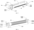
FIG. 1 is a structural diagram of a window shade of the present disclosure; -
FIG. 2 is a structural diagram of a second base, a motor, a cord, a winder, and a battery holder; -
FIG. 3 is an enlarged view of A shown inFIG. 2 ; -
FIG. 4 is a structural diagram of an end cap; -
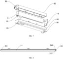
FIG. 5 is a structural diagram of the winder; -
FIG. 6 is a structural diagram of the winder from another perspective; -
FIG. 7 is a structural diagram of the battery holder and a power supply battery; and -
FIG. 8 is a bottom view of the motorized window shade. - Reference Numerals: 1. first base; 2. second base; 3. honeycomb fabric; 4. motor; 5. winder; 6. cord; 7. power supply battery; 8. PLC circuit monitoring unit; 9. battery holder; 21. first sidewall; 22. second sidewall; 23. top wall; 24. end cap; 25. mounting chamber; 26. housing; 27. bottom plate; 28. mounting port; 31. cord hole; 51. positioning seat; 52. spool; 71. power supply interface; 91. first shell; 92. second shell; 93. wire hole; 94. threaded hole; 95. clamping piece; 211. first clamping strip; 212. second clamping strip; 213. fifth clamping strip; 214. seventh clamping strip; 221. third clamping strip; 222. fourth clamping strip; 223. sixth clamping strip; 224. eighth clamping strip; 241. closure plate; 242. first clamping plate; 243. second clamping plate; 244. third clamping plate; 245. fourth clamping plate; 246. fifth clamping plate; 247. charging connector; 271. first hook; 272. second hook; 511. first bracket; 512. second bracket; 513. connecting plate; 5111. ring; 5112. first elastic strip; 5113. second elastic strip; 5114. first bump; 5115. second bump; 5121. second ring; 5122. third elastic strip; 5123. fourth elastic strip; 5124. third bump; 5125. fourth bump; and 5131. through hole.
- The specific implementations of the present disclosure are described in further detail below with reference to the drawings and embodiments. The following embodiments are used to illustrate the present disclosure, rather than to limit the scope of the present disclosure.
- It should be understood that, in the description of the present disclosure, the terms such as "central", "longitudinal", "transverse", "long", "wide", "thick", "upper", "lower", "front", "back", "left", "right", "vertical", "horizontal", "top", "bottom", "inner", "outer", "clockwise", "anticlockwise", "axial", "radial" and "circumferential" are intended to indicate orientations shown in the drawings. It should be noted that these terms are merely intended to facilitate a simple description of the present disclosure, rather than to indicate or imply that the mentioned apparatus or elements must have the specific orientation or be constructed and operated in the specific orientation. Therefore, these terms may not be construed as a limitation to the present disclosure.
- It should be noted that, in the description of the present disclosure, unless otherwise clearly specified that, meanings of terms "mount", "connect" and "communicate" should be understood in a broad sense. For example, a connection may be a fixed connection, a removable connection, or an integral connection; may be a mechanical connection or an electrical connection; may be a direct connection or an indirect connection via an intermediate medium; or may be intercommunication between two components. Those of ordinary skill in the art may understand specific meanings of the above terms in the present disclosure based on a specific situation.
- It should be understood that in the description of the present disclosure, the terms such as "first" and "second" are intended to describe various information, but the information is not limited to these terms, and these terms are only used to distinguish the same type of information from each other. For example, without departing from the scope of the present disclosure, "first" information may be referred to as "second" information, and similarly, "second" information may be referred to as "first" information.
- As shown in
FIGS. 1 to 3 and8 , an embodiment provides a window shade. The window shade includes a first base 1, asecond base 2 located below the first base 1 and spaced from the first base 1,honeycomb fabric 3 clamped between the first base 1 and thesecond base 2, amotor 4 provided on thesecond base 2, awinder 5 connected to an output end of themotor 4, acord 6, a battery holder 9, and apower supply battery 7 provided on the battery holder 9. - The
second base 2 is provided with a mountingchamber 25. The mountingchamber 25 runs through thesecond base 2 from left to right. Two ends of thesecond base 2 are respectively provided withdetachable end caps 24. After thewinder 5 and other components are provided in the mountingchamber 25, the end caps 24 cover the two ends of thesecond base 2 to prevent dust from entering the mountingchamber 25. The mountingchamber 25 is provided with oppositely arranged first sidewall 21 andsecond sidewall 22. The first sidewall 21 and thesecond sidewall 22 are horizontally spaced from each other. The first sidewall 21 is provided with afirst clamping strip 211 and a second clamping strip 212 spaced from top to bottom. Thefirst clamping strip 211 and the second clamping strip 212 extend along the mountingchamber 25. Thesecond sidewall 22 is provided with athird clamping strip 221 and afourth clamping strip 222 spaced from top to bottom. Thethird clamping strip 221 and thefourth clamping strip 222 extend along the mountingchamber 25. - The
power supply battery 7 is a lithium battery. Thepower supply battery 7 is electrically connected to themotor 4 through a wire. Thehoneycomb fabric 3 has an upper end fixedly connected to the first base 1 and a lower end fixedly connected to thesecond base 2. Thecord 6 includes one end connected to an output end of thewinder 5 and the other end connected to the first base 1. When themotor 4 drives thewinder 5 to rotate in one direction, thewinder 5 winds thecord 6, such that thesecond base 2 moves upward close to the first base 1 to open the window shade. When themotor 4 drives thewinder 5 to rotate in an opposite direction, thewinder 5 releases thecord 6, such that thesecond base 2 moves downward away from the first base 1 to close the window shade. - The
second base 2 is provided with a chargingconnector 247. The chargingconnector 247 is electrically connected to thepower supply battery 7. A battery holder 9 is provided in the mountingchamber 25. The battery holder 9 includes one side clamped between thefirst clamping strip 211 and the second clamping strip 212 and the other side clamped between thethird clamping strip 221 and thefourth clamping strip 222. In this design, one side of the battery holder 9 is clamped between thefirst clamping strip 211 and the second clamping strip 212, and the other side of the battery holder 9 is clamped between thethird clamping strip 221 and thefourth clamping strip 222. The design realizes positioning of the battery holder 9, without the need for fasteners such as screws, and realizes easy and rapid mounting of the battery holder 9. The power supply battery is charged by an external cable through the chargingconnector 247. When thepower supply battery 7 needs to be charged, the power supply battery does not need to be disassembled, which avoids the trouble of disassembling the power supply battery and improves convenience of the window shade. - As shown in
FIGS. 1 to 3 , thewinder 5 is provided on thesecond base 2. Thewinder 5 is provided at a lower position to facilitate maintenance of the window shade. The winder includes aspool 52 and apositioning seat 51. Thespool 52 is rotatably provided on thepositioning seat 51. The first base 1 is fixedly provided on an upper edge of a window. Thecord 6 includes one end wound on thespool 52 and the other end connected to the first base 1. Thespool 52 is rotated to wind up or release thecord 6, so as to allow thesecond base 2 to move upward or downward. When themotor 4 drives thespool 52 of thewinder 5 to rotate in one direction, thespool 52 of thewinder 5 winds up thecord 6, such that thesecond base 2 moves upward close to the first base 1 to open the window shade. When themotor 4 drives thespool 52 of thewinder 5 to rotate in the opposite direction, thespool 52 of thewinder 5 releases thecord 6, such that thesecond base 2 moves downward away from the first base 1 to close the window shade. - Two ends of one side of the
positioning seat 51 are clamped between thefirst clamping strip 211 and the second clamping strip 212 and two ends of another side of thepositioning seat 51 are clamped between thethird clamping strip 221 and thefourth clamping strip 222. When theend cap 24 is opened, the positioningseat 51 slides into the mountingchamber 25 from an opening of the mountingchamber 25. Meanwhile, the two ends of one side of thepositioning seat 51 are clamped between thefirst clamping strip 211 and the second clamping strip 212, and the two ends of another side of thepositioning seat 51 are clamped between thethird clamping strip 221 and thefourth clamping strip 222. Theend cap 24 is closed to realize mounting and positioning of thepositioning seat 51. The mounting avoids fasteners such as screws, and is easy and fast. - Specifically, in an embodiment, the
spool 52 is tapered, and the cord is wound into a tapered shape on thespool 52, which realizes simple and reliable winding. - Specifically, in an embodiment, left and right ends of the
second base 2 are respectively provided with mountingports 28 communicated with the mountingchamber 25. The battery holder 9 enters from the mountingport 28 and is provided in the mountingchamber 25. - Specifically, in an embodiment, the charging
connector 247 is a universal serial bus (USB) interface. The USB interface is adapted to the charging plug of the existing mobile phone and other electronic products, so the charging plug of the mobile phone can be used for charging. - As shown in
FIGS. 2 ,5 and 6 , specifically, in an embodiment, the positioningseat 51 includes afirst bracket 511 and asecond bracket 512 spaced from each other. Thespool 52 includes one end rotatably provided on thefirst bracket 511 and the other end rotatably provided on thesecond bracket 512. One end of thefirst bracket 511 and one end of thesecond bracket 512 are clamped between thefirst clamping strip 211 and the second clamping strip 212, and the other end of thefirst bracket 511 and the other end of thesecond bracket 512 are clamped between thethird clamping strip 221 and thefourth clamping strip 222. - Specifically, in an embodiment, the positioning
seat 51 further includes a connectingplate 513 connecting thefirst bracket 511 and thesecond bracket 512. The connectingplate 513 is provided with a throughhole 5131 through which thecord 6 passes. The connectingplate 513 connects thefirst bracket 511 and thesecond bracket 512 to strengthen the stability between thefirst bracket 511 and thesecond bracket 512, such that thespool 52 can rotate stably. - Specifically, in an embodiment, the
first bracket 511 includes afirst ring 5111, a firstelastic strip 5112 provided on an outer circumferential side of thefirst ring 5111, and a secondelastic strip 5113 provided on the outer circumferential side of thefirst ring 5111. Thespool 52 is rotatably provided on an inner ring of thefirst ring 5111. The firstelastic strip 5112 and the secondelastic strip 5113 are tangent to thefirst ring 5111, and the firstelastic strip 5112 and the secondelastic strip 5113 are horizontally spaced from each other. The firstelastic strip 5112 is provided with afirst bump 5114 for being clamped between thefirst clamping strip 211 and the second clamping strip 212, and the secondelastic strip 5113 is provided with asecond bump 5115 for being clamped between thethird clamping strip 221 and thefourth clamping strip 222. Thefirst bump 5114 extends to the first sidewall 21 and is clamped between thefirst clamping strip 211 and the second clamping strip 212, and thesecond bump 5115 extends to thesecond sidewall 22 and is clamped between thethird clamping strip 221 and thefourth clamping strip 222. - Specifically, in an embodiment, a distance between the first
elastic strip 5112 and the secondelastic strip 5113 gradually increases in a direction away from thefirst ring 5111. The firstelastic strip 5112 and the secondelastic strip 5113 are elastic. A distance between an end of the firstelastic strip 5112 away from thefirst ring 5111 and an end of the secondelastic strip 5113 away from thefirst ring 5111 is greater than a diameter of thespool 52 and greater than a distance between the first sidewall 21 and thesecond sidewall 22. Thefirst bump 5114 is stably clamped between thefirst clamping strip 211 and the second clamping strip 212 through the elasticity of the firstelastic strip 5112, and thesecond bump 5115 is stably clamped between thethird clamping strip 221 and thefourth clamping strip 222 through the elasticity of the secondelastic strip 5113. - Specifically, in an embodiment, the
second bracket 512 includes asecond ring 5121, a thirdelastic strip 5122 provided on an outer circumferential side of thesecond ring 5121, and a fourthelastic strip 5123 provided on the outer circumferential side of thesecond ring 5121. Thespool 52 is rotatably provided on an inner ring of thesecond ring 5121. The thirdelastic strip 5122 and the fourthelastic strip 5123 are tangent to thesecond ring 5121, and the thirdelastic strip 5122 and the fourthelastic strip 5123 are horizontally spaced from each other. The thirdelastic strip 5122 is provided with athird bump 5124 for being clamped between thefirst clamping strip 211 and the second clamping strip 212, and the fourthelastic strip 5123 is provided with afourth bump 5125 for being clamped between thethird clamping strip 221 and thefourth clamping strip 222. Thethird bump 5124 extends to the first sidewall 21 and is clamped between thefirst clamping strip 211 and the second clamping strip 212, and thefourth bump 5125 extends to thesecond sidewall 22 and is clamped between thethird clamping strip 221 and thefourth clamping strip 222. - Specifically, in an embodiment, a distance between the third
elastic strip 5122 and the fourthelastic strip 5123 gradually increases in a direction away from thesecond ring 5121. The thirdelastic strip 5122 and the fourthelastic strip 5123 are elastic. A distance between an end of the thirdelastic strip 5122 away from thesecond ring 5121 and an end of the fourthelastic strip 5123 away from thesecond ring 5121 is greater than a diameter of thespool 52 and greater than a distance between the first sidewall 21 and thesecond sidewall 22. Thethird bump 5124 is stably clamped between thefirst clamping strip 211 and the second clamping strip 212 through the elasticity of the thirdelastic strip 5122, and thefourth bump 5125 is stably clamped between thethird clamping strip 221 and thefourth clamping strip 222 through the elasticity of the fourthelastic strip 5123. - Specifically, in an embodiment, the mounting
chamber 25 is further provided with atop wall 23 connecting the first sidewall 21 and thesecond sidewall 22. The first sidewall 21 is further provided with afifth clamping strip 213, and thesecond sidewall 22 is further provided with asixth clamping strip 223. Two ends of one side of the connectingplate 513 are clamped between thefifth clamping strip 213 and thetop wall 23 and two ends of another side of the connectingplate 513 are clamped between thesixth clamping strip 223 and thetop wall 23. Since thefifth clamping strip 213 and thetop wall 23 clamp the two ends of one side of the connectingplate 513 and thesixth clamping strip 223 and thetop wall 23 clamp the two ends of the other side of the connectingplate 513, the connectingplate 513 is stably mounted to avoid displacement of thepositioning seat 51 in case thespool 52 is stuck. Therefore, the positioningseat 51 is stable enough without the need for screws. - As shown in
FIGS. 2 ,3 ,4 and8 , specifically, in an embodiment, theend cap 24 is provided with aclosure plate 241, afirst clamping plate 242 connected to theclosure plate 241 and clamped between thefirst clamping strip 211 and the second clamping strip 212, and asecond clamping plate 243 connected to theclosure plate 241 and clamped between thethird clamping strip 221 and thefourth clamping strip 222. Thefirst clamping plate 242 and thesecond clamping plate 243 are horizontally spaced from each other. Through thefirst clamping plate 242 and thesecond clamping plate 243, theend cap 24 is detachably connected to thesecond base 2 to facilitate maintenance of themotor 4 and the power supply battery. When the battery holder 9 is provided in the mountingchamber 25, theend cap 24 covers the mountingport 28. Theend cap 24 is intended to prevent dust and protect themotor 4, the power supply battery, and the battery holder 9. There are twoend caps 24, which respectively cover the mountingports 28 at the left and right ends of thesecond base 2. - Specifically, in an embodiment, the
end cap 24 is further provided with athird clamping plate 244 connected to theclosure plate 241 and clamped between thefirst clamping strip 211 and thefifth clamping strip 213, and afourth clamping plate 245 connected to theclosure plate 241 and clamped between thethird clamping strip 221 and thesixth clamping strip 223. Thethird clamping plate 244 and thefirst clamping plate 242 are spaced from top to bottom, and thefifth clamping strip 213 is clamped between thefirst clamping plate 242 and thethird clamping plate 244. Thefourth clamping plate 245 and thesecond clamping plate 243 are spaced from top to bottom, and thesixth clamping strip 223 is clamped between thefourth clamping plate 245 and thesecond clamping plate 243. Thethird clamping plate 244 and thefourth clamping plate 245 strengthen the connection between theend cap 24 and thesecond base 2. - Specifically, in an embodiment, the
end cap 24 is further provided with afifth clamping plate 246 connected to theclosure plate 241 and clamped into the mountingchamber 25. Thefifth clamping plate 246 is located at a lower end of theclosure board 241, and the chargingconnector 247 is located on thefifth clamping plate 246. The chargingconnector 247 is located at a lower end of thefifth clamping plate 246 of theend cap 24. That is, after theend cap 24 is covered, the chargingconnector 247 on theend cap 24 is located on a lower end surface of theend cap 24. Theend cap 24 eases charging by the charging connector, and realizes aesthetics. - As shown in
FIGS. 2 and3 , specifically, in an embodiment, thesecond base 2 includes ahousing 26 and abottom plate 27. Thehousing 26 and thebottom plate 27 are detachably connected and enclose the mountingchamber 25. The first sidewall 21 and thesecond sidewall 22 are located on thehousing 26. The first sidewall 21 is further provided with aseventh clamping strip 214, and thesecond sidewall 22 is further provided with aneighth clamping strip 224. Thebottom plate 27 is provided with afirst hook 271 clamped between theseventh clamping strip 214 and the second clamping strip 212, and asecond hook 272 clamped between theeighth clamping strip 224 and thefourth clamping strip 222. Theseventh clamping strip 214 and theeighth clamping strip 224 are spaced from each other. Theseventh clamping strip 214 and theeighth clamping strip 224 are extended to be close to each other. Theseventh clamping strip 214 and theeighth clamping strip 224 are located at a lower end of thehousing 26 and are smoothly connected to thehousing 26. Thefirst hook 271 and thesecond hook 272 are spaced from each other and connected to an upper end surface of thebottom plate 27. Thefirst hook 271 and thesecond hook 272 each are Z-shaped. Thefirst hook 271 is clamped between theeighth clamping strip 224 and thefourth clamping strip 222, and thesecond hook 272 is clamped between theeighth clamping strip 224 and thefourth clamping strip 222. In this way, the mounting and removal of thebottom plate 27 are realized by sliding thebottom plate 27 horizontally. - As shown in
FIG. 1 , specifically, in an embodiment, thehoneycomb fabric 3 is provided therein with acord hole 31 running through thehoneycomb fabric 3 from top to bottom. Thecord 6 includes the one end wound on thespool 52 and the other end connected to the first base 1 through thecord hole 31. Thecord 6 is hidden to realize aesthetic appearance of the window shade. - As shown in
FIGS. 2 ,3 and7 , specifically, in an embodiment, the battery holder 9 includes afirst shell 91 and asecond shell 92 detachably provided on thefirst shell 91. Thefirst shell 91 and thesecond shell 92 enclose a receiving chamber for receiving thepower supply battery 7. Thefirst shell 91 is provided with aclamping piece 95, and theclamping piece 95 has an isosceles-trapezoid cross-section. Thefirst shell 91 is provided with awire hole 93 communicated with the receiving chamber. A wire is connected to the chargingconnector 247 and thepower supply battery 7 through thewire hole 93. The clampingpiece 95 includes one end clamped between thefirst clamping strip 211 and the second clamping strip 212 and the other end clamped between thethird clamping strip 221 and thefourth clamping strip 222. - Specifically, in an embodiment, the
second shell 92 is provided with a threadedhole 94 threaded to thesecond base 2. One side of thefirst shell 91 and one side of thesecond shell 92 are clamped between thefirst clamping strip 211 and thefifth clamping strip 213, and the other side of thefirst shell 91 and the other side of thesecond shell 92 are clamped between thethird clamping strip 221 and thesixth clamping strip 223. Thefirst clamping strip 211, thefifth clamping strip 213, thethird clamping strip 221, and thesixth clamping strip 223 jointly clamp thefirst shell 91 and thesecond shell 92 to avoid thefirst shell 91 and thesecond shell 92 being separated in the mountingchamber 25. - As shown in
FIGS. 2 and7 , specifically, in an embodiment, the window shade further includes a programmable logic controller (PLC)circuit monitoring unit 8 for monitoring a voltage of thepower supply battery 7. Themotor 4 is connected in a transmission manner to thespool 52, and the PLCcircuit monitoring unit 8 is electrically connected to themotor 4. Thepower supply battery 7 is provided with apower supply interface 71 electrically connected to the PLCcircuit monitoring unit 8. Themotor 4 is a direct-current (DC) motor with low power consumption and a low speed of 34 r/min. Themotor 4 operates normally at 6.7-7.4 V, and shakes when the voltage drops below 6.7 V to prompt the user that thepower supply battery 7 is out of power and needs to be recharged. The normal supply voltage of the lithium battery is 7.4 V As the operation time increases, the output voltage of thepower supply battery 7 decreases gradually. When it drops to 6.7 V, the PLCcircuit monitoring unit 8 detects that the current in the circuit drops. However, themotor 4 continues to work for 4.5 cycles each time when the PLCcircuit monitoring unit 8 receives a control signal. A Hall element in the PLCcircuit monitoring unit 8 inductively counts the working cycles of themotor 4. When the number of the working cycles of the motor reaches 4.5, the PLCcircuit monitoring unit 8 stops supplying power to themotor 4, thus controlling themotor 4 not to work continuously, so as to prompt the user to recharge the lithium battery. When the voltage of the lithium battery drops below 6.4 V, themotor 4 stops completely. - The above described are merely preferred implementations of the present disclosure. It should be noted that those of ordinary skill in the art may further make several improvements and modifications without departing from the principle of the present disclosure, but such improvements and modifications should be deemed as falling within the protection scope of the present disclosure.
Claims (10)
- A window shade, comprising a first base (1), a second base (2) located below the first base (1) and spaced from the first base (1), honeycomb fabric (3) clamped between the first base (1) and the second base (2), a motor (4) provided on the second base (2), a winder (5) connected to an output end of the motor (4), a cord (6), a battery holder (9), and a power supply battery (7) provided on the battery holder (9), wherein the power supply battery (7) is electrically connected to the motor (4); and the cord (6) comprises one end connected to an output end of the winder (5) and the other end connected to the first base (1); and
the second base (2) is provided with a mounting chamber (25) and a charging connector (247); the charging connector (247) is electrically connected to the power supply battery (7); the mounting chamber (25) is provided with a first sidewall (21) and a second sidewall (22) oppositely arranged; the first sidewall (21) is provided with a first clamping strip (211) and a second clamping strip (212) spaced from top to bottom; the second sidewall (22) is provided with a third clamping strip (221) and a fourth clamping strip (222) spaced from top to bottom; and the battery holder (9) comprises one side clamped between the first clamping strip (211) and the second clamping strip (212) and the other side clamped between the third clamping strip (221) and the fourth clamping strip (222). - The window shade according to claim 1, wherein the window shade further comprises a programmable logic controller (PLC) circuit monitoring unit (8) for monitoring a voltage of the power supply battery (7) and electrically connected to the motor (4).
- The window shade according to claim 1, wherein the winder (5) comprises a spool (52) and a positioning seat (51); the cord (6) comprises the one end wound on the spool (52); and two ends of one side of the positioning seat (51) are clamped between the first clamping strip (211) and the second clamping strip (212) and two ends of another side of the positioning seat (51) are clamped between the third clamping strip (221) and the fourth clamping strip (222).
- The window shade according to claim 3, wherein the positioning seat (51) comprises a first bracket (511) and a second bracket (512) spaced from each other, and a connecting plate (513) connecting the first bracket (511) and the second bracket (512); the connecting plate (513) is provided with a through hole (5131) through which the cord (6) passes; the spool (52) comprises one end rotatably provided on the first bracket (511) and the other end rotatably provided on the second bracket (512); and one end of the first bracket (511) and one end of the second bracket (512) are clamped between the first clamping strip (211) and the second clamping strip (212), and the other end of the first bracket (511) and the other end of the second bracket (512) are clamped between the third clamping strip (221) and the fourth clamping strip (222).
- The window shade according to claim 4, wherein the first bracket (511) comprises a first ring (5111), a first elastic strip (5112) provided on an outer circumferential side of the first ring (5111), and a second elastic strip (5113) provided on the outer circumferential side of the first ring (5111); the first elastic strip (5112) and the second elastic strip (5113) are spaced from each other; the first elastic strip (5112) is provided with a first bump (5114) for being clamped between the first clamping strip (211) and the second clamping strip (212), and the second elastic strip (5113) is provided with a second bump (5115) for being clamped between the third clamping strip (221) and the fourth clamping strip (222); and a distance between the first elastic strip (5112) and the second elastic strip (5113) gradually increases in a direction away from the first ring (5111); and
the second bracket (512) comprises a second ring (5121), a third elastic strip (5122) provided on an outer circumferential side of the second ring (5121), and a fourth elastic strip (5123) provided on the outer circumferential side of the second ring (5121); the third elastic strip (5122) and the fourth elastic strip (5123) are spaced from each other; the third elastic strip (5122) is provided with a third bump (5124) for being clamped between the first clamping strip (211) and the second clamping strip (212), and the fourth elastic strip (5123) is provided with a fourth bump (5125) for being clamped between the third clamping strip (221) and the fourth clamping strip (222); and a distance between the third elastic strip (5122) and the fourth elastic strip (5123) gradually increases in a direction away from the second ring (5121). - The window shade according to claim 5, wherein the mounting chamber (25) is further provided with a top wall (23) connecting the first sidewall (21) and the second sidewall (22); the first sidewall (21) is further provided with a fifth clamping strip (213), and the second sidewall (22) is further provided with a sixth clamping strip (223); and two ends of one side of the connecting plate (513) are clamped between the fifth clamping strip (213) and the top wall (23) and two ends of another side of the connecting plate (513) are clamped between the sixth clamping strip (223) and the top wall (23).
- The window shade according to claim 1, wherein the charging connector (247) is a universal serial bus (USB) interface.
- The window shade according to claim 2, wherein an end of the second base (2) is further provided with a mounting port (28) communicated with the mounting chamber (25); and the battery holder (9) enters from the mounting port (28) and is provided in the mounting chamber (25).
- The window shade according to claim 8, wherein the second base (2) is provided with an end cap (24) covering the mounting port (28); and the end cap (24) is provided with a closure plate (241), a first clamping plate (242) connected to the closure plate (241) and clamped between the first clamping strip (211) and the second clamping strip (212), and a second clamping plate (243) connected to the closure plate (241) and clamped between the third clamping strip (221) and the fourth clamping strip (222).
- The window shade according to any one of claims 1 to 9, wherein the honeycomb fabric (3) is provided therein with a cord hole (31) running through the honeycomb fabric (3) from top to bottom; and the cord (6) comprises the one end wound on the spool (52) and the other end connected to the first base (1) through the cord hole (31).
Applications Claiming Priority (3)
| Application Number | Priority Date | Filing Date | Title |
|---|---|---|---|
| CN202220024548.XU CN217001612U (en) | 2022-01-05 | 2022-01-05 | Charging type curtain |
| CN202220024547.5U CN217354198U (en) | 2022-01-05 | 2022-01-05 | Curtain |
| PCT/CN2022/092951 WO2023130639A1 (en) | 2022-01-05 | 2022-05-16 | Curtain |
Publications (2)
| Publication Number | Publication Date |
|---|---|
| EP4230833A1 true EP4230833A1 (en) | 2023-08-23 |
| EP4230833A4 EP4230833A4 (en) | 2024-02-28 |
Family
ID=86992496
Family Applications (1)
| Application Number | Title | Priority Date | Filing Date |
|---|---|---|---|
| EP22830356.6A Withdrawn EP4230833A4 (en) | 2022-01-05 | 2022-05-16 | Curtain |
Country Status (2)
| Country | Link |
|---|---|
| US (1) | US20230212910A1 (en) |
| EP (1) | EP4230833A4 (en) |
Families Citing this family (2)
| Publication number | Priority date | Publication date | Assignee | Title |
|---|---|---|---|---|
| USD1012555S1 (en) * | 2022-03-23 | 2024-01-30 | Shenzhen World New Power Co. Ltd | Motorised curtain rail |
| USD1012554S1 (en) * | 2022-03-23 | 2024-01-30 | Shenzhen World New Power Co. Ltd | Motorised curtain rail |
Family Cites Families (3)
| Publication number | Priority date | Publication date | Assignee | Title |
|---|---|---|---|---|
| FR3011873B1 (en) * | 2013-10-11 | 2015-12-11 | Somfy Sas | MOTORIZED MOTORIZED INSTALLATION OF A SCREEN AND ASSOCIATED SCREEN DEVICE |
| TWM608822U (en) * | 2020-09-03 | 2021-03-11 | 慶豐富實業股份有限公司 | Electric window curtain |
| CN214035472U (en) * | 2020-10-27 | 2021-08-24 | 广东创明遮阳科技有限公司 | A curtain placed under a driving mechanism |
-
2022
- 2022-05-16 EP EP22830356.6A patent/EP4230833A4/en not_active Withdrawn
-
2023
- 2023-01-18 US US18/155,766 patent/US20230212910A1/en not_active Abandoned
Also Published As
| Publication number | Publication date |
|---|---|
| EP4230833A4 (en) | 2024-02-28 |
| US20230212910A1 (en) | 2023-07-06 |
Similar Documents
| Publication | Publication Date | Title |
|---|---|---|
| US20230212910A1 (en) | Window shade | |
| CN108729836B (en) | Charging system and charging method of electric curtain | |
| US10547190B2 (en) | Rechargeable powered covering for a architectural opening | |
| US20100060081A1 (en) | System and Method for Providing Power to Portable Electronic Devices | |
| JP7527053B1 (en) | Mounting device for motorized curtains | |
| JP3223337U (en) | Control device for raising and lowering the curtain | |
| CN204846160U (en) | Bicycle basket battery | |
| CN217712367U (en) | Window curtain | |
| CN217001612U (en) | Charging type curtain | |
| CN219041448U (en) | Mobile power supply | |
| CN223068332U (en) | Mounting device for electric curtain | |
| CN201518373U (en) | Automatic power line winding box | |
| CN112804596B (en) | Indoor 5G network basic station rail set that removes of hospital | |
| WO2023130639A1 (en) | Curtain | |
| CN215169591U (en) | Curtain and control device thereof | |
| CN217354198U (en) | Curtain | |
| CN210629163U (en) | Wall-hanging wireless precious ventilation structure that charges | |
| CN113482512A (en) | Window curtain | |
| CN215835140U (en) | Clamping type alternating current wireless charger | |
| KR102369937B1 (en) | Driving device for converting to electric blind | |
| CN215499209U (en) | Additional device for making card type digital camera compatible to palm DV | |
| CN214341620U (en) | Automatic opening and closing device for curtain | |
| CN211958082U (en) | Switch power plug structure | |
| CN216190125U (en) | Electric shock prevention cable winding machine | |
| CN217282313U (en) | Power supply mechanism, electronic equipment and curtain system |
Legal Events
| Date | Code | Title | Description |
|---|---|---|---|
| STAA | Information on the status of an ep patent application or granted ep patent |
Free format text: STATUS: UNKNOWN |
|
| STAA | Information on the status of an ep patent application or granted ep patent |
Free format text: STATUS: THE INTERNATIONAL PUBLICATION HAS BEEN MADE |
|
| PUAI | Public reference made under article 153(3) epc to a published international application that has entered the european phase |
Free format text: ORIGINAL CODE: 0009012 |
|
| STAA | Information on the status of an ep patent application or granted ep patent |
Free format text: STATUS: REQUEST FOR EXAMINATION WAS MADE |
|
| 17P | Request for examination filed |
Effective date: 20230105 |
|
| AK | Designated contracting states |
Kind code of ref document: A1 Designated state(s): AL AT BE BG CH CY CZ DE DK EE ES FI FR GB GR HR HU IE IS IT LI LT LU LV MC MK MT NL NO PL PT RO RS SE SI SK SM TR |
|
| A4 | Supplementary search report drawn up and despatched |
Effective date: 20240126 |
|
| RIC1 | Information provided on ipc code assigned before grant |
Ipc: E06B 9/322 20060101ALI20240122BHEP Ipc: H01M 50/244 20210101ALI20240122BHEP Ipc: E06B 9/262 20060101AFI20240122BHEP |
|
| DAV | Request for validation of the european patent (deleted) | ||
| DAX | Request for extension of the european patent (deleted) | ||
| GRAP | Despatch of communication of intention to grant a patent |
Free format text: ORIGINAL CODE: EPIDOSNIGR1 |
|
| STAA | Information on the status of an ep patent application or granted ep patent |
Free format text: STATUS: GRANT OF PATENT IS INTENDED |
|
| RIC1 | Information provided on ipc code assigned before grant |
Ipc: E06B 9/322 20060101ALI20240827BHEP Ipc: H01M 50/244 20210101ALI20240827BHEP Ipc: E06B 9/262 20060101AFI20240827BHEP |
|
| INTG | Intention to grant announced |
Effective date: 20240917 |
|
| STAA | Information on the status of an ep patent application or granted ep patent |
Free format text: STATUS: THE APPLICATION IS DEEMED TO BE WITHDRAWN |
|
| 18D | Application deemed to be withdrawn |
Effective date: 20250118 |