EP4230817A1 - A 3d printed building element - Google Patents
A 3d printed building element Download PDFInfo
- Publication number
- EP4230817A1 EP4230817A1 EP22157015.3A EP22157015A EP4230817A1 EP 4230817 A1 EP4230817 A1 EP 4230817A1 EP 22157015 A EP22157015 A EP 22157015A EP 4230817 A1 EP4230817 A1 EP 4230817A1
- Authority
- EP
- European Patent Office
- Prior art keywords
- layer
- block
- masonry structure
- blocks
- bottom edge
- Prior art date
- Legal status (The legal status is an assumption and is not a legal conclusion. Google has not performed a legal analysis and makes no representation as to the accuracy of the status listed.)
- Granted
Links
Images


Classifications
-
- E—FIXED CONSTRUCTIONS
- E04—BUILDING
- E04B—GENERAL BUILDING CONSTRUCTIONS; WALLS, e.g. PARTITIONS; ROOFS; FLOORS; CEILINGS; INSULATION OR OTHER PROTECTION OF BUILDINGS
- E04B2/00—Walls, e.g. partitions, for buildings; Wall construction with regard to insulation; Connections specially adapted to walls
- E04B2/02—Walls, e.g. partitions, for buildings; Wall construction with regard to insulation; Connections specially adapted to walls built-up from layers of building elements
- E04B2/04—Walls having neither cavities between, nor in, the solid elements
- E04B2/06—Walls having neither cavities between, nor in, the solid elements using elements having specially-designed means for stabilising the position
-
- E—FIXED CONSTRUCTIONS
- E04—BUILDING
- E04B—GENERAL BUILDING CONSTRUCTIONS; WALLS, e.g. PARTITIONS; ROOFS; FLOORS; CEILINGS; INSULATION OR OTHER PROTECTION OF BUILDINGS
- E04B2/00—Walls, e.g. partitions, for buildings; Wall construction with regard to insulation; Connections specially adapted to walls
- E04B2/02—Walls, e.g. partitions, for buildings; Wall construction with regard to insulation; Connections specially adapted to walls built-up from layers of building elements
- E04B2/14—Walls having cavities in, but not between, the elements, i.e. each cavity being enclosed by at least four sides forming part of one single element
- E04B2/16—Walls having cavities in, but not between, the elements, i.e. each cavity being enclosed by at least four sides forming part of one single element using elements having specially-designed means for stabilising the position
-
- B—PERFORMING OPERATIONS; TRANSPORTING
- B33—ADDITIVE MANUFACTURING TECHNOLOGY
- B33Y—ADDITIVE MANUFACTURING, i.e. MANUFACTURING OF THREE-DIMENSIONAL [3D] OBJECTS BY ADDITIVE DEPOSITION, ADDITIVE AGGLOMERATION OR ADDITIVE LAYERING, e.g. BY 3D PRINTING, STEREOLITHOGRAPHY OR SELECTIVE LASER SINTERING
- B33Y80/00—Products made by additive manufacturing
-
- B—PERFORMING OPERATIONS; TRANSPORTING
- B28—WORKING CEMENT, CLAY, OR STONE
- B28B—SHAPING CLAY OR OTHER CERAMIC COMPOSITIONS; SHAPING SLAG; SHAPING MIXTURES CONTAINING CEMENTITIOUS MATERIAL, e.g. PLASTER
- B28B1/00—Producing shaped prefabricated articles from the material
- B28B1/001—Rapid manufacturing of 3D objects by additive depositing, agglomerating or laminating of material
-
- E—FIXED CONSTRUCTIONS
- E04—BUILDING
- E04B—GENERAL BUILDING CONSTRUCTIONS; WALLS, e.g. PARTITIONS; ROOFS; FLOORS; CEILINGS; INSULATION OR OTHER PROTECTION OF BUILDINGS
- E04B2/00—Walls, e.g. partitions, for buildings; Wall construction with regard to insulation; Connections specially adapted to walls
- E04B2/02—Walls, e.g. partitions, for buildings; Wall construction with regard to insulation; Connections specially adapted to walls built-up from layers of building elements
- E04B2002/0202—Details of connections
- E04B2002/0243—Separate connectors or inserts, e.g. pegs, pins or keys
- E04B2002/0245—Pegs or pins
Definitions
- the present invention relates to the field of 3D printed building element, in particular a 3D printed masonry structure for a building.
- the invention has been developed with particular reference to a 3D printed block of a masonry structure, and a method for producing a 3D printed masonry structure.
- a known method, as in CN109594777 , to manufacturing a 3D printed building wall is to provide a large-scale 3D printer on site and direct printing from the bottom to the top a plurality of stackered layers. After the printing of a flat layer is completed, the next flat layer is printed there above.
- This method which allows to provide 3D printed wall with high load-bearing capacity, has his own drawbacks in particular in case of large building wall. It requires a reciprocating printing movement on a flat layer which can be very large, and it needs an extreme stability to achieve high-precision printing.
- the size of the device is often limited due to factors such as printing accuracy, device stability, device transmission performance, and device manufacturability, the size of the printed building wall is often reduced.
- the building element comprises a top and a bottom flat surfaces defining a plane parallel to the ground, so that only vertical and squared wall can be manufactured.
- a 3D printed building element comprising:
- a masonry structure 10 comprises multiple blocks 20, 20', 20" disposed according to a predetermined configuration.
- the masonry structure 10 in Fig. 1 for example, comprises three layers each comprising a plurality of blocks 20, 20', 20" respectively, wherein the first layer lays on the ground, the second layer is stackered on the first layer and the third layer is stackered on the second layer.
- Each block 20, 20', 20", of the embodiment shown in Figures 3 to 6 has a rectangular shape in plan, with two pairs of congruent opposite sides, and with two sides longer than the other two sides.
- Each block 20 20, 20', 20" comprises an upper wall 24, a front wall 26, a rear wall 28 and two lateral walls 29, defining an inner space 27.
- the lower portions of the walls 24, 26, 28, 29 define an inner edge developing seamlessly to form a bottom edge surface 22.
- the bottom edge surface 22 of the blocks 20 of the first layer lays on the ground
- the bottom edge surface 22 of the blocks 20' of the second layer lays on the upper wall 24 of the blocks of the first layer
- the bottom edge surface 22 of the blocks 20" of the third layer lays on the upper wall 24 of the blocks of the second layer.
- each block 20, 20', 20" contribute to create, respectively, the front wall and the rear wall of the entire masonry structure 10, and they can comprise predetermined surface texture.
- the lateral walls 29 of a first block 20, 20', 20" are faced to the lateral walls 29 of a second and a third blocks 20, 20', 20" disposed laterally adjacent to the first block 20, 20', 20" on the same layer.
- each block 20, 20', 20" shown in Figures 1 to 6 are given only as an example, and they can be modified without exit from the scope of protection of the present application.
- a block 20, 20', 20" may have a square or trapezoidal or even triangular cross-section or shape in plan.
- each block 20, 20', 20" comprises two internal ducts 34.
- Each duct 34 defines a first feedthrough opening 30 provided on the upper wall 24, and an opposite second feedthrough opening 32 facing the bottom edge surface 22.
- Each unit block further comprises two connecting elements 50, each inserted in a corresponding duct 34 of a block 20, 20', 20", so that a first portion 52 of the connection element 50 is exposed outside the first feedthrough opening 30 provided on the upper wall 24 and is suitable to be inserted in a second feedthrough opening 32 facing the bottom edge surface 22 of a duct 34 of a further block 20', 20".
- each duct 34 comprises two internal abutments 40, 42.
- the first internal abutment 40 can be provided in the upper portion of the duct 34 and the second internal abutment 42 can be provided in the lower portion of the duct 34.
- Each internal abutment 40, 42 is suitable to block the insertion of the connecting element 50 inside the duct 34 and to allow the upper portion of the connecting element 50 to be exposed outside the first feedthrough opening 30, or to allow the lower portion of the connecting element 50 to be exposed outside the second feedthrough opening 30.
- each connecting element 50 comprises a central abutment 52, an external diameter of the central abutment 52 being greater than an internal diameter of the duct 34.
- the connecting element 50 allow to firmly connect one block 20', 20" superimposed to two adjacent blocks 20, 20' and to provide to the entire masonry structure a very high load-bearing capacity.
- each connection element 50 can be filled with a reinforcing element, i.e. a metal frame, and/or material, i.e. concrete, in order to reinforce the overall structure.
- a reinforcing element i.e. a metal frame
- material i.e. concrete
- each connection element 50 can be used to house electrical wires or to house hydraulic pipes.
- a plurality of blocks 20 may comprise two feedthrough openings 30 provided on the upper wall 24 thereof, a corresponding duct 34 and a bottom wall closing the inner space 27.
- This plurality of blocks 20 are suitable to be placed on the ground and to form a first layer of the masonry structure.
- each block 20, 20', 20" of the present invention may be manufactured with a different shape and a dimension so as to build a large number of different masonry structures.
- a masonry structure 100 comprises a plurality of blocks 20, 20', 20" each having a non-polygonal cross-section so as to reproduce a spherical segment.
- the masonry structure of Figure 7 may be completed in order to create a dome.
- each block 20 has an annulus sector shape, and the bottom edge surface 22 of the first layer of blocks 20 define a plane parallel to the ground, while the upper wall 24 thereof define a plane tangent to the ground so as to create the curved masonry structure.
- the blocks 20, 20', 20" of each layer are keep together with the blocks 20, 20', 20" of the upper or lower stackered layer with the connecting elements 50.
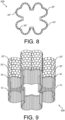
- a masonry structure 200 has a "four-leaf clover" shape in plan.
- the masonry structure comprises a plurality of stackered layers, each comprising a plurality of blocks 20, 20', 20".
- Each block 20, 20', 20" has a non-polygonal cross-section so as to reproduce a spherical segment.
- each block 20 has an annulus sector shape, and the bottom edge surface 22 and upper wall 24 of each block 20, 20', 20" in each layer of blocks define two parallel planes parallel to the ground.
- Each block 20, 20', 20” may comprise a different annulus sector shape with respect to the annulus sector shape of another block 20, 20', 20" so that each layer of blocks shall reproduce the "four-leaf clover" shape in plan.
- each layer may further comprise a connecting block 21, with a further different shape in plan, which allows to connect each other the "leaves" of the masonry structure.
- a plurality of blocks 20 may comprise feedthrough openings 32 facing the bottom edge surface 22 of the block 20 and connecting the corresponding duct 34.
- the plurality of blocks 20 may further comprises one or more anchoring elements 51, for example an elongated rod, connected to each block 20, for example each inserted in the corresponding duct 34 of the block 20.
- This plurality of blocks 20 is suitable to be placed on the ground and to form a first layer of the masonry structure, and the anchoring elements 51 are suitable to be inserted in the ground in order to anchor the masonry structure to the ground and increase its stability.
- the 3D printed building element consists of a mixture of recycled plastic and wood from manufacturing waste. More in details, the material of the 3D printed building element comprises 50% in weight of recycled plastic and 50 % in weight of wood from manufacturing waste.
- a method for manufacturing a masonry structure of 3D printed building elements comprises the steps of:
- the method may further comprise the following steps:
Landscapes
- Engineering & Computer Science (AREA)
- Architecture (AREA)
- Chemical & Material Sciences (AREA)
- Manufacturing & Machinery (AREA)
- Materials Engineering (AREA)
- Physics & Mathematics (AREA)
- Electromagnetism (AREA)
- Civil Engineering (AREA)
- Structural Engineering (AREA)
- Retaining Walls (AREA)
- Toys (AREA)
Abstract
Description
- The present invention relates to the field of 3D printed building element, in particular a 3D printed masonry structure for a building. The invention has been developed with particular reference to a 3D printed block of a masonry structure, and a method for producing a 3D printed masonry structure.
- A known method, as in
CN109594777 , to manufacturing a 3D printed building wall is to provide a large-scale 3D printer on site and direct printing from the bottom to the top a plurality of stackered layers. After the printing of a flat layer is completed, the next flat layer is printed there above. - This method, which allows to provide 3D printed wall with high load-bearing capacity, has his own drawbacks in particular in case of large building wall. It requires a reciprocating printing movement on a flat layer which can be very large, and it needs an extreme stability to achieve high-precision printing.
- Since the size of the device is often limited due to factors such as printing accuracy, device stability, device transmission performance, and device manufacturability, the size of the printed building wall is often reduced.
- Besides the logistic and set-up problems on site of these printers, they normally use materials which are not eco-friendly, such as, for example, a quick-setting mortar extruded layer by layer.
- Another drawback of the know masonry structures made of 3D printed building elements is that the building element comprises a top and a bottom flat surfaces defining a plane parallel to the ground, so that only vertical and squared wall can be manufactured.
- It is therefore a general object of the present invention to create a building element that is manufactured using the 3D printing process, that has a high load-bearing capacity, that allows to create curved or inclined masonry structure, and that is made of eco-friendly materials.
- In view of this object the idea which has occurred to the Applicant is that of providing, according to the invention, a 3D printed building element comprising:
- a 3D printed block comprising an upper wall, a front wall, a rear wall and two lateral walls, defining an inner space, the lower portions of the walls defining an inner edge developing seamlessly to form a bottom edge surface;
- two internal ducts disposed in the inner space, each defining a first feedthrough opening provided on the upper wall, and an opposite second feedthrough opening facing the bottom edge surface;
- the building element further comprises two connecting elements, each inserted in a corresponding duct, so that a first portion of the connection element is exposed outside the first feedthrough opening provided on the upper wall and is suitable to be inserted in a second feedthrough opening facing the bottom edge surface of a duct of a further block superimposed to the block.
- Further technical features and advantages of the present invention will become clearer from the description, given only by way of example, with reference to the accompanying figures, in which:
-
Figure 1 is a schematic frontal view of a masonry structure according to the present invention; -
Figure 2 is an isometric view of the masonry structure ofFigure 1 ; -
Figure 3 is a bottom view of a 3D printed block according to the present invention; -
Figure 4 is a sectional view along line IV-IV ofFigure 3 ; -
Figure 5 is a sectional view along line V-V ofFigure 3 ; -
Figure 6 is an isometric view of the connection step of two 3D printed blocks according to the present invention; -
Figure 7 is an isometric view of one of the embodiments of a masonry structure according to the present invention; -
Figure 8 is a top view of another one of the embodiments of a masonry structure according to the present invention; and - .
Figure 9 is an isometric view of the embodiment ofFigure 8 . - It is to be understood that elements or technical features of one embodiment may be conveniently incorporated in other embodiments without further clarifications.
- Reference will now be made in detail to the various embodiments of the invention. Each example is provided merely by way of illustration of the invention and is understood as not being a limitation thereof. For example, the technical features shown or described since they form part of an embodiment may be adopted in, or associated with, other embodiments in order to produce a further embodiment. It is understood that the present invention will be inclusive of these modifications and variants.
- According to one of the preferred embodiments of the present invention, a
masonry structure 10 comprisesmultiple blocks masonry structure 10 inFig. 1 , for example, comprises three layers each comprising a plurality ofblocks - Each
block Figures 3 to 6 , has a rectangular shape in plan, with two pairs of congruent opposite sides, and with two sides longer than the other two sides. Eachblock 20 20, 20', 20" comprises anupper wall 24, afront wall 26, arear wall 28 and twolateral walls 29, defining aninner space 27. The lower portions of thewalls bottom edge surface 22. - According to the embodiment of
Figures 1 and 2 , thebottom edge surface 22 of theblocks 20 of the first layer lays on the ground, thebottom edge surface 22 of the blocks 20' of the second layer lays on theupper wall 24 of the blocks of the first layer, and thebottom edge surface 22 of theblocks 20" of the third layer lays on theupper wall 24 of the blocks of the second layer. - The
front wall 26 and therear wall 28 of eachblock entire masonry structure 10, and they can comprise predetermined surface texture. - The
lateral walls 29 of afirst block lateral walls 29 of a second and athird blocks first block - The shape and the dimension of each
block Figures 1 to 6 are given only as an example, and they can be modified without exit from the scope of protection of the present application. For example, ablock - As clearly shown in
Figures 3 to 5 , eachblock internal ducts 34. Eachduct 34 defines afirst feedthrough opening 30 provided on theupper wall 24, and an oppositesecond feedthrough opening 32 facing thebottom edge surface 22. - Each unit block further comprises two connecting
elements 50, each inserted in acorresponding duct 34 of ablock first portion 52 of theconnection element 50 is exposed outside the first feedthrough opening 30 provided on theupper wall 24 and is suitable to be inserted in asecond feedthrough opening 32 facing thebottom edge surface 22 of aduct 34 of afurther block 20', 20". According to the embodiment shown in the figures, eachduct 34 comprises twointernal abutments internal abutment 40 can be provided in the upper portion of theduct 34 and the secondinternal abutment 42 can be provided in the lower portion of theduct 34. - Each
internal abutment element 50 inside theduct 34 and to allow the upper portion of the connectingelement 50 to be exposed outside the first feedthrough opening 30, or to allow the lower portion of the connectingelement 50 to be exposed outside thesecond feedthrough opening 30. - According to the embodiment shown in the figures, each connecting
element 50 comprises acentral abutment 52, an external diameter of thecentral abutment 52 being greater than an internal diameter of theduct 34. - According to this configuration, the connecting
element 50 allow to firmly connect oneblock 20', 20" superimposed to twoadjacent blocks 20, 20' and to provide to the entire masonry structure a very high load-bearing capacity. - According to a further embodiment, each
connection element 50 can be filled with a reinforcing element, i.e. a metal frame, and/or material, i.e. concrete, in order to reinforce the overall structure. - Alternatively, each
connection element 50 can be used to house electrical wires or to house hydraulic pipes. - According to a further embodiment of the present invention a plurality of
blocks 20 may comprise twofeedthrough openings 30 provided on theupper wall 24 thereof, acorresponding duct 34 and a bottom wall closing theinner space 27. This plurality ofblocks 20 are suitable to be placed on the ground and to form a first layer of the masonry structure. - As stated above, each
block Figure 7 , amasonry structure 100 comprises a plurality ofblocks Figure 7 may be completed in order to create a dome. - In order to realize such a spherical segment, each
block 20 has an annulus sector shape, and thebottom edge surface 22 of the first layer ofblocks 20 define a plane parallel to the ground, while theupper wall 24 thereof define a plane tangent to the ground so as to create the curved masonry structure. - Due to the curvature of the masonry structure, the
blocks blocks connecting elements 50. - With particular reference to
Figures 8 and 9 , amasonry structure 200 according to a further embodiment of the present invention has a "four-leaf clover" shape in plan. The masonry structure comprises a plurality of stackered layers, each comprising a plurality ofblocks block block 20 has an annulus sector shape, and thebottom edge surface 22 andupper wall 24 of eachblock block block - For example, each layer may further comprise a connecting block 21, with a further different shape in plan, which allows to connect each other the "leaves" of the masonry structure.
- With particular reference to the embodiment shown in
Figure 9 , a plurality ofblocks 20 may comprisefeedthrough openings 32 facing thebottom edge surface 22 of theblock 20 and connecting thecorresponding duct 34. The plurality ofblocks 20 may further comprises one ormore anchoring elements 51, for example an elongated rod, connected to eachblock 20, for example each inserted in thecorresponding duct 34 of theblock 20. - This plurality of
blocks 20 is suitable to be placed on the ground and to form a first layer of the masonry structure, and theanchoring elements 51 are suitable to be inserted in the ground in order to anchor the masonry structure to the ground and increase its stability. - According to one of the embodiments of the present invention, the 3D printed building element consists of a mixture of recycled plastic and wood from manufacturing waste. More in details, the material of the 3D printed building element comprises 50% in weight of recycled plastic and 50 % in weight of wood from manufacturing waste.
- In use, a method for manufacturing a masonry structure of 3D printed building elements comprises the steps of:
- identifying multiple unit blocks according to the
masonry structure 10; - 3D printing all the
blocks ducts 34 of themasonry structure 10 according to the technical features above described; - transporting the unit blocks to the building site, and
- manufacturing a
masonry structure 10 of 3D printed building elements. - The method may further comprise the following steps:
- place a first layer of
multiple blocks 20 on the ground, - inserting a plurality of
connection elements 50 into thefeedthrough openings 32 provided on theupper wall 24 of eachblock 20 of the first layer, - superimposing a second layer of blocks 20' on the first layer by inserting a
first connection element 50 of ablock 20 of the first layer in afeedthrough opening 32 provided on thebottom edge surface 22 of a first block 20' of the second layer, and inserting asecond connector element 50 of thesame block 20 of the first layer in afeedthrough opening 32 provided on thebottom edge surface 22 of a second block 20' of the second layer disposed adjacent to the first block 20' of the second layer.
Claims (9)
- A 3D printed building element comprising:- a 3D printed block (20) comprising an upper wall (24), a front wall (26), a rear wall (28) and two lateral walls (29), defining an inner space (27), the lower portions of the walls (24, 26, 28, 29) defining an inner edge developing seamlessly to form a bottom edge surface (22);- two internal ducts (34) disposed in the inner space (27), each defining a first feedthrough opening (30) provided on the upper wall (24), and an opposite second feedthrough opening (32) facing the bottom edge surface (22);the building element further comprises two connecting elements (50), each inserted in a corresponding duct (34) of the block (20), so that a first portion (52) of the connection element (50) is exposed outside the first feedthrough opening (30) provided on the upper wall (24) and is suitable to be inserted in a second feedthrough opening (32) facing the bottom edge surface (22) of a duct (34) of a further block (20) superimposed to the block (20).
- A 3D printed building element according to claim 1, characterised in that each duct (34) comprises two internal abutments (40, 42), the first internal abutment (40) provided in the upper portion of the duct (34) and the second internal abutment (42) provided in the lower portion of the duct (34).
- A 3D printed building element according to claim 2, characterised in that the connecting element (50) comprises a central abutment (52), an external diameter of the central abutment (52) being greater than an internal diameter of the duct (34).
- A masonry structure comprising a plurality of 3D printed building elements according to claims 1 to 3, wherein it comprises- a first layer of multiple blocks (20),- a plurality of connection elements (50) inserted into the feedthrough openings (32) provided on the upper wall (24) of each block (20) of the first layer,- a second layer of blocks (20) superimposed on the first layer, and wherein- a first connection element (50) of a block (20) of the first layer is inserted in a feedthrough opening (32) provided on the bottom edge surface (22) of a first block (20') of the second layer, and a second connector element (50) of the same block (20) of the first layer in inserted in a feedthrough opening (32) provided on the bottom edge surface (22) of a second block (20') of the second layer disposed adjacent to the first block (20') of the second layer.
- A masonry structure according to claim 5, characterised in that a connection element (50) is filled with a reinforcing element in order to reinforce the overall structure.
- A masonry structure according to claim 5, characterised in that the reinforcing element is a metal frame and/or concrete.
- A masonry structure according to claim 4, characterised in that it further comprises a plurality of anchoring elements (51) connected to a plurality of blocks (20) of the first layer of the masonry structure.
- A method for manufacturing a masonry structure of 3D printed building elements according to claims 4 to 7, comprising the steps of:- identifying multiple unit blocks according to the masonry structure (10),- 3D printing all the blocks (20, 20', 20") and the ducts (34) of the masonry structure (10),- transporting the unit blocks to the building site, and- manufacturing a masonry structure 10 of 3D printed building elements.
- The method according to claim 8, characterised in that it further comprises the steps of:- place a first layer of multiple blocks (20) on the ground,- inserting a plurality of connection elements (50) into the feedthrough openings (32) provided on the upper wall (24) of each block (20) of the first layer,- superimposing a second layer of blocks (20)' on the first layer by inserting a first connection element (50) of a block (20) of the first layer in a feedthrough opening (32) provided on the bottom edge surface (22) of a first block (20') of the second layer, and inserting a second connector element (50) of the same block (20) of the first layer in a feedthrough opening (32) provided on the bottom edge surface (22) of a second block (20') of the second layer disposed adjacent to the first block (20') of the second layer.
Priority Applications (5)
| Application Number | Priority Date | Filing Date | Title |
|---|---|---|---|
| EP22157015.3A EP4230817B1 (en) | 2022-02-16 | 2022-02-16 | A 3d printed building element |
| ES22157015T ES2992183T3 (en) | 2022-02-16 | 2022-02-16 | A 3D printed building element |
| CN202380018898.2A CN118613623A (en) | 2022-02-16 | 2023-02-15 | 3D printed building components |
| PCT/EP2023/053697 WO2023156422A1 (en) | 2022-02-16 | 2023-02-15 | A 3d printed building element |
| US18/834,045 US20250137250A1 (en) | 2022-02-16 | 2023-02-15 | A 3d printed building element |
Applications Claiming Priority (1)
| Application Number | Priority Date | Filing Date | Title |
|---|---|---|---|
| EP22157015.3A EP4230817B1 (en) | 2022-02-16 | 2022-02-16 | A 3d printed building element |
Publications (3)
| Publication Number | Publication Date |
|---|---|
| EP4230817A1 true EP4230817A1 (en) | 2023-08-23 |
| EP4230817C0 EP4230817C0 (en) | 2024-09-04 |
| EP4230817B1 EP4230817B1 (en) | 2024-09-04 |
Family
ID=80683027
Family Applications (1)
| Application Number | Title | Priority Date | Filing Date |
|---|---|---|---|
| EP22157015.3A Active EP4230817B1 (en) | 2022-02-16 | 2022-02-16 | A 3d printed building element |
Country Status (5)
| Country | Link |
|---|---|
| US (1) | US20250137250A1 (en) |
| EP (1) | EP4230817B1 (en) |
| CN (1) | CN118613623A (en) |
| ES (1) | ES2992183T3 (en) |
| WO (1) | WO2023156422A1 (en) |
Families Citing this family (1)
| Publication number | Priority date | Publication date | Assignee | Title |
|---|---|---|---|---|
| DE102024124661A1 (en) * | 2024-08-29 | 2026-03-05 | Bundesrepublik Deutschland (Bundesanstalt für Materialforschung und -prüfung) | Method for manufacturing a wall, building element for constructing a wall, building element set and building shell |
Citations (5)
| Publication number | Priority date | Publication date | Assignee | Title |
|---|---|---|---|---|
| US3430404A (en) * | 1967-03-20 | 1969-03-04 | George B Muse | Apertured wall construction |
| US20160130810A1 (en) * | 2014-08-01 | 2016-05-12 | Just Biofiber Corp. | Load bearing interlocking structural blocks and modular building system |
| CN109594777A (en) | 2019-01-17 | 2019-04-09 | 中国建筑第八工程局有限公司 | Building-brick type builds 3D printing method and apparatus |
| CN110424577A (en) * | 2019-08-20 | 2019-11-08 | 深圳市三通特发科技有限公司 | A kind of Wedge-type self assembly 3D printing customization partition block |
| GB2592843A (en) * | 2019-05-16 | 2021-09-15 | Orsi Joe | A complete building construction system for constructing walls eaves, roof and floors |
Family Cites Families (46)
| Publication number | Priority date | Publication date | Assignee | Title |
|---|---|---|---|---|
| US2236926A (en) * | 1938-02-17 | 1941-04-01 | Ohlen C Surface | Dowel |
| IL25148A (en) * | 1965-03-02 | 1970-09-17 | Fischer Artur | Building bricks for incorporation in a constructional toy |
| US3479782A (en) * | 1967-08-04 | 1969-11-25 | George B Muse | Construction block |
| NL6800094A (en) * | 1968-01-03 | 1969-07-07 | ||
| US3864885A (en) * | 1969-02-26 | 1975-02-11 | George B Muse | Wall structures |
| US3689075A (en) * | 1970-07-31 | 1972-09-05 | Adelson Louis | Three-dimensional puzzles |
| US3966339A (en) * | 1975-02-21 | 1976-06-29 | Borivoj Nemecek | Fasteners |
| GB1559636A (en) * | 1976-07-05 | 1980-01-23 | Baupres Ag | Building block |
| US4454699A (en) * | 1982-03-15 | 1984-06-19 | Fred Strobl | Brick fastening device |
| NL8503134A (en) * | 1985-11-14 | 1987-06-01 | Cornelia Petronella Maria West | BUILDING ELEMENT AND CONNECTORS FOR CONNECTING BUILT-UP ELEMENTS. |
| US4947610A (en) * | 1989-04-13 | 1990-08-14 | Robert Koerner | Method and apparatus for building a brick wall |
| CA2158771C (en) * | 1995-09-21 | 1999-08-10 | David W. Fielding | Drywall construction and means therefor |
| US5771650A (en) * | 1997-03-14 | 1998-06-30 | Kingswood, Inc. | Interlocking building block system |
| DK174518B1 (en) * | 1999-01-15 | 2003-05-05 | Lego As | A toy |
| GB0010297D0 (en) * | 2000-07-24 | 2000-06-14 | Fawcett Norman | Block construction |
| NL1016174C1 (en) * | 2000-09-14 | 2002-03-15 | Maria Aletta De Haan Medevoort | Method for constructing a building, block and dowel for it. |
| GB0026290D0 (en) * | 2000-10-27 | 2000-12-13 | Herbison Francis D | Spacer element |
| US7186050B2 (en) * | 2002-02-27 | 2007-03-06 | L & P Property Management Company | Pole connector assembly and method for racks and shelving |
| DE20303476U1 (en) * | 2003-03-05 | 2003-07-03 | Knickenberg, Andreas, 45355 Essen | Element to be used for joining wooden bricks for creative use in playground or at outdoor activities of children and youths |
| US6996945B2 (en) * | 2003-05-16 | 2006-02-14 | Doty Steven E | Self interlocking block system |
| ITMI20041638A1 (en) * | 2004-08-06 | 2004-11-06 | P M Stampi 2 S R L | BUILDING ELEMENT |
| US7241095B2 (en) * | 2005-04-07 | 2007-07-10 | Driv-Lok, Inc. | Dowel with locking features and method of using the same |
| PA8631001A1 (en) * | 2005-04-21 | 2005-12-23 | Soloarmar Panama S A | SOLOARAR |
| US7267598B2 (en) * | 2005-06-07 | 2007-09-11 | Connector Set Limited Partnership | Interfacings between block type and rod and connector type construction toy sets |
| US7517270B2 (en) * | 2006-05-30 | 2009-04-14 | Minds-I, Inc. | Construction system |
| US20080075528A1 (en) * | 2006-09-22 | 2008-03-27 | Michael Marzetta | Construction system |
| BE1018236A5 (en) * | 2008-07-31 | 2010-07-06 | Rolf Theodorus Suibertus Antonius | CONNECTION ELEMENT FOR BUILDING BLOCKS, BUILDING BLOCK, NUTS AND KITS OF SUCH ELEMENTS. |
| US9010059B2 (en) * | 2011-01-31 | 2015-04-21 | Value Chain Network (Hong Kong) Limited | Building blocks and building block fasteners |
| WO2012162834A1 (en) * | 2011-05-31 | 2012-12-06 | Maeers Richard | Construction blocks |
| DE202011105691U1 (en) * | 2011-09-15 | 2012-12-17 | 1 Pure Design Srl | Wooden Toys |
| RO129241B1 (en) * | 2012-07-30 | 2017-08-30 | Laurenţiu Dumitru Breaz | Storage basin and method for making the same |
| US8905812B2 (en) * | 2013-02-11 | 2014-12-09 | Cheng Pai-Chen | Toy block |
| KR101386209B1 (en) * | 2013-07-12 | 2014-04-17 | 박영택 | Brick connectors for assembly |
| KR101493939B1 (en) * | 2013-12-09 | 2015-02-17 | 박영택 | brick rectangular connectors for assembly |
| KR20160128326A (en) * | 2014-02-03 | 2016-11-07 | 락도웰 인코퍼레이티드 | Cinch fastening device |
| WO2017183981A2 (en) * | 2016-04-21 | 2017-10-26 | Jarola Vision B.V. | Modular construction system, coupling element, object, tool and packaging |
| PL3445466T3 (en) * | 2016-04-21 | 2023-08-28 | Jarola Vision B.V. | Modular construction system, coupling element, object, tool and packaging |
| WO2017201633A1 (en) * | 2016-05-26 | 2017-11-30 | Sic Spa | Device for connecting and separating masonry units |
| GB201711734D0 (en) * | 2017-07-21 | 2017-09-06 | Munro Sawmills Ltd | Improved Dowel |
| WO2019106133A1 (en) * | 2017-12-01 | 2019-06-06 | Lego A/S | An additively manufactured toy building brick |
| BR112020010254A2 (en) * | 2017-12-01 | 2020-11-10 | Lego A/S | toy building blocks produced from biopolymeric material |
| KR102190324B1 (en) * | 2018-11-12 | 2020-12-11 | 김태명 | A Set of Assemble-able Bricks |
| KR102342288B1 (en) * | 2019-07-05 | 2021-12-22 | 최원옥 | Slab construction structure using earthquake-resistant blocks |
| KR102342256B1 (en) * | 2019-08-08 | 2021-12-22 | 이승구 | Binding unit for mutual assembly of stone blocks |
| GB2584739B (en) * | 2019-11-29 | 2021-06-09 | Vistafolia Ltd | Modular wall unit |
| IT202000007156A1 (en) * | 2020-04-03 | 2021-10-03 | Fulvio Monteverde | TOY BUILDING ELEMENT AND TOY BUILDING SET |
-
2022
- 2022-02-16 ES ES22157015T patent/ES2992183T3/en active Active
- 2022-02-16 EP EP22157015.3A patent/EP4230817B1/en active Active
-
2023
- 2023-02-15 WO PCT/EP2023/053697 patent/WO2023156422A1/en not_active Ceased
- 2023-02-15 US US18/834,045 patent/US20250137250A1/en active Pending
- 2023-02-15 CN CN202380018898.2A patent/CN118613623A/en active Pending
Patent Citations (5)
| Publication number | Priority date | Publication date | Assignee | Title |
|---|---|---|---|---|
| US3430404A (en) * | 1967-03-20 | 1969-03-04 | George B Muse | Apertured wall construction |
| US20160130810A1 (en) * | 2014-08-01 | 2016-05-12 | Just Biofiber Corp. | Load bearing interlocking structural blocks and modular building system |
| CN109594777A (en) | 2019-01-17 | 2019-04-09 | 中国建筑第八工程局有限公司 | Building-brick type builds 3D printing method and apparatus |
| GB2592843A (en) * | 2019-05-16 | 2021-09-15 | Orsi Joe | A complete building construction system for constructing walls eaves, roof and floors |
| CN110424577A (en) * | 2019-08-20 | 2019-11-08 | 深圳市三通特发科技有限公司 | A kind of Wedge-type self assembly 3D printing customization partition block |
Also Published As
| Publication number | Publication date |
|---|---|
| EP4230817C0 (en) | 2024-09-04 |
| ES2992183T3 (en) | 2024-12-10 |
| WO2023156422A1 (en) | 2023-08-24 |
| US20250137250A1 (en) | 2025-05-01 |
| EP4230817B1 (en) | 2024-09-04 |
| CN118613623A (en) | 2024-09-06 |
Similar Documents
| Publication | Publication Date | Title |
|---|---|---|
| US6434900B1 (en) | Prefabricated concrete wall system | |
| CN105658882B (en) | concrete block spacing system | |
| EP0163117A1 (en) | Bettered, high thermal, and/or sound insulating modular elements suitable for buildings | |
| EP0392861A1 (en) | Method and apparatus for building a brick wall | |
| GB2062062A (en) | Building blocks wall structures made therefrom and methods of making the same | |
| WO2008131288A2 (en) | Special and improved configurations for unitized post tension block system for masonry structures | |
| GB2077802A (en) | Blast and fragment-resistant protective wall structure | |
| CA2444337A1 (en) | Fire/party wall system | |
| US20250137250A1 (en) | A 3d printed building element | |
| KR102567893B1 (en) | A prefabricated wall using concrete structure | |
| CN109695291B (en) | Double-deck coincide prefabricated outer wall structure of basement | |
| CN102791934A (en) | Building elements and building systems using such building elements | |
| KR20220049811A (en) | Seismic retrofit method of masonry buildings using reinforcement strip | |
| PL248651B1 (en) | Thermal insulation inserts for eliminating thermal bridges in walls made of blocks | |
| JP4902377B2 (en) | Basic structure of concrete block fence and its construction method | |
| CN215948580U (en) | Masonry infilled wall without constructional columns | |
| JP3517398B2 (en) | Decorative plate block and its structure | |
| AU2010201627A1 (en) | Construction block | |
| CN107268837B (en) | Assembled expanded stone wallboard and combined installation method thereof | |
| EP4491819A1 (en) | Building block | |
| JP3199087U (en) | Top-end unit block body of a civil engineering building block | |
| EP4667674A1 (en) | Constructive element for the construction of partitions in architecture | |
| JP3199083U (en) | Intermediate unit block body for civil engineering building blocks | |
| JP7692851B2 (en) | Concrete block foundation structure | |
| JPH03107047A (en) | Slab construction method |
Legal Events
| Date | Code | Title | Description |
|---|---|---|---|
| PUAI | Public reference made under article 153(3) epc to a published international application that has entered the european phase |
Free format text: ORIGINAL CODE: 0009012 |
|
| STAA | Information on the status of an ep patent application or granted ep patent |
Free format text: STATUS: THE APPLICATION HAS BEEN PUBLISHED |
|
| AK | Designated contracting states |
Kind code of ref document: A1 Designated state(s): AL AT BE BG CH CY CZ DE DK EE ES FI FR GB GR HR HU IE IS IT LI LT LU LV MC MK MT NL NO PL PT RO RS SE SI SK SM TR |
|
| STAA | Information on the status of an ep patent application or granted ep patent |
Free format text: STATUS: REQUEST FOR EXAMINATION WAS MADE |
|
| 17P | Request for examination filed |
Effective date: 20240105 |
|
| RBV | Designated contracting states (corrected) |
Designated state(s): AL AT BE BG CH CY CZ DE DK EE ES FI FR GB GR HR HU IE IS IT LI LT LU LV MC MK MT NL NO PL PT RO RS SE SI SK SM TR |
|
| RIN1 | Information on inventor provided before grant (corrected) |
Inventor name: FANTINELLI, DAVIDE |
|
| GRAP | Despatch of communication of intention to grant a patent |
Free format text: ORIGINAL CODE: EPIDOSNIGR1 |
|
| STAA | Information on the status of an ep patent application or granted ep patent |
Free format text: STATUS: GRANT OF PATENT IS INTENDED |
|
| INTG | Intention to grant announced |
Effective date: 20240405 |
|
| GRAS | Grant fee paid |
Free format text: ORIGINAL CODE: EPIDOSNIGR3 |
|
| GRAA | (expected) grant |
Free format text: ORIGINAL CODE: 0009210 |
|
| STAA | Information on the status of an ep patent application or granted ep patent |
Free format text: STATUS: THE PATENT HAS BEEN GRANTED |
|
| AK | Designated contracting states |
Kind code of ref document: B1 Designated state(s): AL AT BE BG CH CY CZ DE DK EE ES FI FR GB GR HR HU IE IS IT LI LT LU LV MC MK MT NL NO PL PT RO RS SE SI SK SM TR |
|
| REG | Reference to a national code |
Ref country code: GB Ref legal event code: FG4D |
|
| REG | Reference to a national code |
Ref country code: CH Ref legal event code: EP |
|
| REG | Reference to a national code |
Ref country code: IE Ref legal event code: FG4D |
|
| REG | Reference to a national code |
Ref country code: DE Ref legal event code: R096 Ref document number: 602022005762 Country of ref document: DE |
|
| U01 | Request for unitary effect filed |
Effective date: 20240927 |
|
| U07 | Unitary effect registered |
Designated state(s): AT BE BG DE DK EE FI FR IT LT LU LV MT NL PT RO SE SI Effective date: 20241023 |
|
| REG | Reference to a national code |
Ref country code: ES Ref legal event code: FG2A Ref document number: 2992183 Country of ref document: ES Kind code of ref document: T3 Effective date: 20241210 |
|
| PG25 | Lapsed in a contracting state [announced via postgrant information from national office to epo] |
Ref country code: NO Free format text: LAPSE BECAUSE OF FAILURE TO SUBMIT A TRANSLATION OF THE DESCRIPTION OR TO PAY THE FEE WITHIN THE PRESCRIBED TIME-LIMIT Effective date: 20241204 |
|
| PG25 | Lapsed in a contracting state [announced via postgrant information from national office to epo] |
Ref country code: PL Free format text: LAPSE BECAUSE OF FAILURE TO SUBMIT A TRANSLATION OF THE DESCRIPTION OR TO PAY THE FEE WITHIN THE PRESCRIBED TIME-LIMIT Effective date: 20240904 Ref country code: GR Free format text: LAPSE BECAUSE OF FAILURE TO SUBMIT A TRANSLATION OF THE DESCRIPTION OR TO PAY THE FEE WITHIN THE PRESCRIBED TIME-LIMIT Effective date: 20241205 |
|
| PG25 | Lapsed in a contracting state [announced via postgrant information from national office to epo] |
Ref country code: HR Free format text: LAPSE BECAUSE OF FAILURE TO SUBMIT A TRANSLATION OF THE DESCRIPTION OR TO PAY THE FEE WITHIN THE PRESCRIBED TIME-LIMIT Effective date: 20240904 |
|
| PG25 | Lapsed in a contracting state [announced via postgrant information from national office to epo] |
Ref country code: RS Free format text: LAPSE BECAUSE OF FAILURE TO SUBMIT A TRANSLATION OF THE DESCRIPTION OR TO PAY THE FEE WITHIN THE PRESCRIBED TIME-LIMIT Effective date: 20241204 |
|
| PG25 | Lapsed in a contracting state [announced via postgrant information from national office to epo] |
Ref country code: RS Free format text: LAPSE BECAUSE OF FAILURE TO SUBMIT A TRANSLATION OF THE DESCRIPTION OR TO PAY THE FEE WITHIN THE PRESCRIBED TIME-LIMIT Effective date: 20241204 Ref country code: PL Free format text: LAPSE BECAUSE OF FAILURE TO SUBMIT A TRANSLATION OF THE DESCRIPTION OR TO PAY THE FEE WITHIN THE PRESCRIBED TIME-LIMIT Effective date: 20240904 Ref country code: NO Free format text: LAPSE BECAUSE OF FAILURE TO SUBMIT A TRANSLATION OF THE DESCRIPTION OR TO PAY THE FEE WITHIN THE PRESCRIBED TIME-LIMIT Effective date: 20241204 Ref country code: HR Free format text: LAPSE BECAUSE OF FAILURE TO SUBMIT A TRANSLATION OF THE DESCRIPTION OR TO PAY THE FEE WITHIN THE PRESCRIBED TIME-LIMIT Effective date: 20240904 Ref country code: GR Free format text: LAPSE BECAUSE OF FAILURE TO SUBMIT A TRANSLATION OF THE DESCRIPTION OR TO PAY THE FEE WITHIN THE PRESCRIBED TIME-LIMIT Effective date: 20241205 |
|
| U20 | Renewal fee for the european patent with unitary effect paid |
Year of fee payment: 4 Effective date: 20250220 |
|
| PG25 | Lapsed in a contracting state [announced via postgrant information from national office to epo] |
Ref country code: IS Free format text: LAPSE BECAUSE OF FAILURE TO SUBMIT A TRANSLATION OF THE DESCRIPTION OR TO PAY THE FEE WITHIN THE PRESCRIBED TIME-LIMIT Effective date: 20250104 |
|
| PG25 | Lapsed in a contracting state [announced via postgrant information from national office to epo] |
Ref country code: SM Free format text: LAPSE BECAUSE OF FAILURE TO SUBMIT A TRANSLATION OF THE DESCRIPTION OR TO PAY THE FEE WITHIN THE PRESCRIBED TIME-LIMIT Effective date: 20240904 |
|
| PG25 | Lapsed in a contracting state [announced via postgrant information from national office to epo] |
Ref country code: CZ Free format text: LAPSE BECAUSE OF FAILURE TO SUBMIT A TRANSLATION OF THE DESCRIPTION OR TO PAY THE FEE WITHIN THE PRESCRIBED TIME-LIMIT Effective date: 20240904 |
|
| PG25 | Lapsed in a contracting state [announced via postgrant information from national office to epo] |
Ref country code: SK Free format text: LAPSE BECAUSE OF FAILURE TO SUBMIT A TRANSLATION OF THE DESCRIPTION OR TO PAY THE FEE WITHIN THE PRESCRIBED TIME-LIMIT Effective date: 20240904 |
|
| PLBE | No opposition filed within time limit |
Free format text: ORIGINAL CODE: 0009261 |
|
| STAA | Information on the status of an ep patent application or granted ep patent |
Free format text: STATUS: NO OPPOSITION FILED WITHIN TIME LIMIT |
|
| 26N | No opposition filed |
Effective date: 20250605 |
|
| PG25 | Lapsed in a contracting state [announced via postgrant information from national office to epo] |
Ref country code: MC Free format text: LAPSE BECAUSE OF FAILURE TO SUBMIT A TRANSLATION OF THE DESCRIPTION OR TO PAY THE FEE WITHIN THE PRESCRIBED TIME-LIMIT Effective date: 20240904 |
|
| PG25 | Lapsed in a contracting state [announced via postgrant information from national office to epo] |
Ref country code: IE Free format text: LAPSE BECAUSE OF NON-PAYMENT OF DUE FEES Effective date: 20250216 |
|
| REG | Reference to a national code |
Ref country code: CH Ref legal event code: U11 Free format text: ST27 STATUS EVENT CODE: U-0-0-U10-U11 (AS PROVIDED BY THE NATIONAL OFFICE) Effective date: 20260301 |
|
| U20 | Renewal fee for the european patent with unitary effect paid |
Year of fee payment: 5 Effective date: 20260217 |
|
| PGFP | Annual fee paid to national office [announced via postgrant information from national office to epo] |
Ref country code: GB Payment date: 20260227 Year of fee payment: 5 |
|
| PGFP | Annual fee paid to national office [announced via postgrant information from national office to epo] |
Ref country code: ES Payment date: 20260302 Year of fee payment: 5 |
|
| PGFP | Annual fee paid to national office [announced via postgrant information from national office to epo] |
Ref country code: CH Payment date: 20260301 Year of fee payment: 5 |
|
| PG25 | Lapsed in a contracting state [announced via postgrant information from national office to epo] |
Ref country code: CY Free format text: LAPSE BECAUSE OF FAILURE TO SUBMIT A TRANSLATION OF THE DESCRIPTION OR TO PAY THE FEE WITHIN THE PRESCRIBED TIME-LIMIT Effective date: 20240904 |
|
| PG25 | Lapsed in a contracting state [announced via postgrant information from national office to epo] |
Ref country code: TR Free format text: LAPSE BECAUSE OF FAILURE TO SUBMIT A TRANSLATION OF THE DESCRIPTION OR TO PAY THE FEE WITHIN THE PRESCRIBED TIME-LIMIT Effective date: 20240904 |