EP4230804A1 - Retainer sleeve design with anti-rotation features for a ground engaging tool - Google Patents
Retainer sleeve design with anti-rotation features for a ground engaging tool Download PDFInfo
- Publication number
- EP4230804A1 EP4230804A1 EP23184836.7A EP23184836A EP4230804A1 EP 4230804 A1 EP4230804 A1 EP 4230804A1 EP 23184836 A EP23184836 A EP 23184836A EP 4230804 A1 EP4230804 A1 EP 4230804A1
- Authority
- EP
- European Patent Office
- Prior art keywords
- retainer
- rib
- rotation
- radially inner
- retainer sleeve
- Prior art date
- Legal status (The legal status is an assumption and is not a legal conclusion. Google has not performed a legal analysis and makes no representation as to the accuracy of the status listed.)
- Granted
Links
Images




Classifications
-
- E—FIXED CONSTRUCTIONS
- E02—HYDRAULIC ENGINEERING; FOUNDATIONS; SOIL SHIFTING
- E02F—DREDGING; SOIL-SHIFTING
- E02F9/00—Component parts of dredgers or soil-shifting machines, not restricted to one of the kinds covered by groups E02F3/00 - E02F7/00
- E02F9/28—Small metalwork for digging elements, e.g. teeth scraper bits
- E02F9/2808—Teeth
- E02F9/2816—Mountings therefor
- E02F9/2833—Retaining means, e.g. pins
-
- E—FIXED CONSTRUCTIONS
- E02—HYDRAULIC ENGINEERING; FOUNDATIONS; SOIL SHIFTING
- E02F—DREDGING; SOIL-SHIFTING
- E02F3/00—Dredgers; Soil-shifting machines
- E02F3/04—Dredgers; Soil-shifting machines mechanically-driven
- E02F3/28—Dredgers; Soil-shifting machines mechanically-driven with digging tools mounted on a dipper- or bucket-arm, i.e. there is either one arm or a pair of arms, e.g. dippers, buckets
- E02F3/36—Component parts
- E02F3/40—Dippers; Buckets ; Grab devices, e.g. manufacturing processes for buckets, form, geometry or material of buckets
-
- E—FIXED CONSTRUCTIONS
- E02—HYDRAULIC ENGINEERING; FOUNDATIONS; SOIL SHIFTING
- E02F—DREDGING; SOIL-SHIFTING
- E02F9/00—Component parts of dredgers or soil-shifting machines, not restricted to one of the kinds covered by groups E02F3/00 - E02F7/00
- E02F9/28—Small metalwork for digging elements, e.g. teeth scraper bits
- E02F9/2808—Teeth
- E02F9/2816—Mountings therefor
- E02F9/2833—Retaining means, e.g. pins
- E02F9/2841—Retaining means, e.g. pins resilient
-
- E—FIXED CONSTRUCTIONS
- E02—HYDRAULIC ENGINEERING; FOUNDATIONS; SOIL SHIFTING
- E02F—DREDGING; SOIL-SHIFTING
- E02F9/00—Component parts of dredgers or soil-shifting machines, not restricted to one of the kinds covered by groups E02F3/00 - E02F7/00
- E02F9/28—Small metalwork for digging elements, e.g. teeth scraper bits
- E02F9/2808—Teeth
- E02F9/2858—Teeth characterised by shape
-
- A—HUMAN NECESSITIES
- A01—AGRICULTURE; FORESTRY; ANIMAL HUSBANDRY; HUNTING; TRAPPING; FISHING
- A01B—SOIL WORKING IN AGRICULTURE OR FORESTRY; PARTS, DETAILS, OR ACCESSORIES OF AGRICULTURAL MACHINES OR IMPLEMENTS, IN GENERAL
- A01B35/00—Other machines for working soil
- A01B35/20—Tools; Details
- A01B35/22—Non-rotating tools; Resilient or flexible mounting of rigid tools
- A01B35/225—Non-rotating tools; Resilient or flexible mounting of rigid tools the tools being adapted to allow the chisel point to be easily fitted or removed from the shank
-
- E—FIXED CONSTRUCTIONS
- E02—HYDRAULIC ENGINEERING; FOUNDATIONS; SOIL SHIFTING
- E02F—DREDGING; SOIL-SHIFTING
- E02F9/00—Component parts of dredgers or soil-shifting machines, not restricted to one of the kinds covered by groups E02F3/00 - E02F7/00
- E02F9/28—Small metalwork for digging elements, e.g. teeth scraper bits
- E02F9/2808—Teeth
- E02F9/2816—Mountings therefor
- E02F9/2825—Mountings therefor using adapters
Definitions
- the first anti-rotation feature 412 may further include a cam surface 438 (may also be referred to as a first transitional surface) extending radially inwardly and circumferentially from the locking surface 416.
- a ramp 440 may also be provided that extends circumferentially from the cam surface 438 to the radially inner annular surface 412.
- the cam surface 438 may have a triangular shape (e.g. a triangular perimeter 438a), and the ramp 440 may include an arcuate surface 442.
- Other configurations of these features are possible in other embodiments of the present disclosure. A discussion of the functions of these various features of the first anti-rotation feature 412 will be discussed later herein.
- any of the ranges of ratios, dimensions, angles, surface areas and/or configurations of various features may be varied as desired or needed including those not specifically mentioned herein.
- blends such as fillets are shown to connect the various surfaces. These may be omitted in other embodiments and it is to be understood that their presence may be ignored sometimes when reading the present specification unless otherwise specifically mentioned.
- a machine, a work implement assembly, a tip assembly, a tip and adapter assembly, a retainer sleeve, a retainer and retainer sleeve assembly and/or any combination of these various assemblies and components may be manufactured, bought, or sold to retrofit a machine or a work implement assembly in the field in an aftermarket context, or alternatively, may be manufactured, bought, sold or otherwise obtained in an OEM (original equipment manufacturer) context.
- OEM original equipment manufacturer
- the rib 418 of the detent feature provides a slight retaining force to hold the retainer 302 in the locked and/or unlocked position. This slight retaining force may be easily overcome by inserting a tool into the drive portion 304 of the retainer 302.
- the first anti-rotation feature 412 provides a more robust retaining force than the detent feature.
- the first anti-rotation feature 412 might refer to the first anti-rotation feature 412 as a primary device for preventing rotation of the retainer 302 while the detent feature might be referred to as a secondary device for preventing rotation of the retainer 302 from the locked to unlocked configuration.
Landscapes
- Engineering & Computer Science (AREA)
- Mining & Mineral Resources (AREA)
- Civil Engineering (AREA)
- General Engineering & Computer Science (AREA)
- Structural Engineering (AREA)
- Mechanical Engineering (AREA)
- Snaps, Bayonet Connections, Set Pins, And Snap Rings (AREA)
- Component Parts Of Construction Machinery (AREA)
- Pit Excavations, Shoring, Fill Or Stabilisation Of Slopes (AREA)
- Soil Working Implements (AREA)
- Suspension Of Electric Lines Or Cables (AREA)
Abstract
Description
- The present disclosure relates to retaining mechanisms employed on work implement assemblies such as bucket assemblies used by earth moving, mining, construction equipment and the like for attaching a tip to an adapter of the work implement assembly. More specifically, the present disclosure relates to a retaining mechanism that uses a retainer sleeve to hold a retainer of the retaining mechanism in a locked or unlocked configuration.
- Machines such as wheel loaders, excavators, and the like employ work implement assemblies including bucket assemblies, rakes, shears, etc. that have teeth or tips attached to them to help perform work on a material such as dirt, rock, sand, etc. For example, teeth or tips may be attached to a bucket assembly to help the bucket assembly to penetrate the ground, facilitating the scooping of the dirt into a bucket, etc. Adapters are often attached to the work edges (e.g. the base edge, the side edge, etc.) of the bucket or other work implement so that different styles of teeth or tips may be attached to the work implement. Also, the tips or teeth may be replaced easily when worn by providing a retaining mechanism that is used to selectively hold the tip onto the adapter or to allow the tip be removed from the adapter.
- These retaining mechanisms may include a plastic retainer sleeve that holds the retainer in the tip. The retainer sleeve may also have features that hold the retainer in a locked or unlocked position to allow replacement of the tips. The retainer sleeve operates in various conditions and operating methods. In extreme operating conditions and methods, a more robust sleeve may be required.
- Accordingly, while current retainer sleeves work well in certain applications, continuous improvement is warranted to provide retainer sleeves suitable for other applications.
- A retainer sleeve according to an embodiment of the present disclosure may comprise a body including an at least partially annular configuration defining an axis of rotation, a radial direction, and a circumferential direction. The body may also comprise a radially inner annular surface defining a radially inner aperture; and a first anti-rotation feature extending radially inwardly from the radially inner annular surface including a sloping ledge having a locking surface that faces at least partially in the circumferential direction and along a direction that is parallel to the axis of rotation, forming an oblique angle with the direction that is parallel to the axis of rotation in a plane perpendicular to the radial direction.
- A retainer sleeve according to another embodiment of the present disclosure may comprise a body including an at least partially annular configuration defining an axis of rotation, a radial direction, a circumferential direction, a first axial end disposed along the axis of rotation, and a second axial end disposed along the axis of rotation. The body may also comprise a radially inner annular surface defining a radially inner aperture, a detent feature including a rib extending radially inwardly from the radially inner annular surface, defining a rib radial height, and a lip disposed at the first axial end extending radially and circumferentially past the rib.
- A retainer and retainer sleeve assembly according to an embodiment of the present disclosure may comprise a retainer including a drive portion, and a lug receiving portion defining a lug receiving slot that extends partially through the lug receiving portion, forming a first sidewall, a second sidewall, and a catch surface connecting the first sidewall to the second sidewall. The lug receiving portion may also include a skirt that at least partially defines the first sidewall, second sidewall, and catch surface. The skirt may terminate at a sloped face that intersects with the first sidewall. The assembly may also comprise a retainer sleeve including a body including an at least partially annular configuration defining an axis of rotation, a radial direction, and a circumferential direction. The body of the retainer sleeve may also include a radially inner annular surface defining a radially inner aperture, and a first anti-rotation feature extending radially inwardly from the radially inner annular surface including a sloping ledge having a locking surface is at least partially complimentarily shaped to engage the sloped face of the skirt of the retainer.
-
-
FIG. 1 is a perspective view of a work implement assembly such as a bucket assembly using tips, adapters, and retaining mechanisms with components configured according to various embodiments of the present disclosure. -
FIG. 2 is a perspective view of a tip and adapter subassembly ofFIG. 1 , shown in isolation from the work implement assembly ofFIG. 1 . -
FIG. 3 is a side sectional view of the tip ofFIG. 2 without the adapter, showing a retaining mechanism and its components including a retainer and a retainer sleeve with anti-rotation and retention features according to an embodiment of the present disclosure in a locked configuration. -
FIG. 4 is a side view of the tip ofFIG. 2 showing the retainer being rotated from a locked to an unlocked configuration. -
FIG. 5 is a partial rear sectional view ofFIG. 2 illustrating a retaining mechanism and its components including the retainer and retainer sleeve with anti-rotation and retention features according to various embodiments of the present disclosure being assembled into the retaining mechanism receiving aperture of the tip. The retainer is shown in an unlocked configuration. -
FIG. 6 is a top oriented perspective view of the retainer and retainer sleeve assembly employed inFIGS. 3 thru 5 removed from the tip for enhanced clarity. -
FIG. 7 is a bottom oriented perspective view of the retainer sleeve ofFIG. 6 shown in isolation. -
FIG. 8 is a front view of the retainer and retainer sleeve assembly ofFIG. 6 with section lines forFIG. 9 . -
FIG. 9 is a top sectional view of the retainer and retainer sleeve assembly ofFIG. 8 taken along lines 9-9 thereof. -
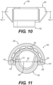
FIG. 10 is a front view of the retainer and retainer sleeve assembly ofFIG. 6 with section lines forFIG. 11 . -
FIG. 11 is a bottom sectional view of the retainer and retainer sleeve assembly ofFIG. 10 taken along lines 11-11 thereof. - Reference will now be made in detail to embodiments of the disclosure, examples of which are illustrated in the accompanying drawings. Wherever possible, the same reference numbers will be used throughout the drawings to refer to the same or like parts. In some cases, a reference number will be indicated in this specification and the drawings will show the reference number followed by a letter for example, 100a, 100b or a prime indicator such as 100', 100"etc. It is to be understood that the use of letters or primes immediately after a reference number indicates that these features are similarly shaped and have similar function such as is often the case when geometry is mirrored about a plane of symmetry. For ease of explanation in this specification, letters or primes will often not be included herein but may be shown in the drawings to indicate duplications of features discussed within this written specification.
- A work implement assembly using tips according to various embodiments of the present disclosure will now be discussed.
- Starting with
FIG. 1 , thework implement assembly 100 may take the form of a bucket assembly 100' that may be used by a wheel loader and that includes anenclosure 101 that defines anopening 102 that communicates with a generally enclosed interior. Starting from the rear of thebucket assembly 100 as shown inFIG. 1 , thebucket assembly 100 includes acurved shell profile 104, which is attached to arear wall 106 at the top end of theshell 104. The other end of the shell is attached to thebottom plate 108 of theassembly 100. Atop plate 110 is attached to the top end of therear wall 106. Thetop plate 110 transitions to aspill guard 112 that is designed to funnel material into the interior of the bucket and prevent material from spilling out of the bucket. Reinforcingribs 119 are provided that are attached to thetop plate 110 and thespill guard 112, providing reinforcement for strength. Two substantiallyflat end plates 114 are attached to the side edges of thespill guard 112,top plate 110,rear wall 106,bottom plate 108 andshell 104. - A
side edge assembly 115 is attached to eachend plate 114 while afront edge assembly 116 is attached to the front edge of thebottom plate 108 of thebucket assembly 100. Thefront edge assembly 116 includes abase edge 117 that is attached to thebottom plate 108, a plurality ofcenter adapters 118 attached to thebase edge 117, and a plurality of tips 200 (may also be referred to as tools, teeth, etc.) with each one of the plurality oftips 200 being attached to one of the plurality ofcenter adapters 118. Also, twocorner adapters 120 are also attached to the base edge and theside edges 122 of the bucket assembly 100'.Tip 200 may also be attached to thecorner adapters 120. - Moreover, a plurality of
base edge protectors 124 are also provided with each one of thebase edge protectors 124 positioned betweencenter adapters 120 and between acenter adapter 120 and acorner adapter 120. Aside edge protector 126 is also provided that is attached to theside edge 122 proximate to acorner adapter 120. - It is to be understood that the work implement assembly may take other forms other than a bucket assembly including rake assemblies, shear assemblies, etc. In addition, a differently configured bucket that is meant to be used by an excavator may also use various embodiments of a tip, retaining mechanism, adapter, spring, spring loaded retainer, tip assembly, and tip and adapter assembly, etc. as will be discussed herein.
- In
FIGS. 2 thru 5 , thetip 200 may comprise abody 202 that defines alongitudinal axis 204, avertical axis 206 that is perpendicular to thelongitudinal axis 204, and alateral axis 208 that is perpendicular to thevertical axis 206, and thelongitudinal axis 204. Thebody 202 may include a forward workingportion 210 disposed along thelongitudinal axis 204 including a closedend 212, and arear attachment portion 214 disposed along thelongitudinal axis 204 including anopen end 216. - The
rear attachment portion 214 defines anexterior surface 218, an adapternose receiving pocket 220 extending longitudinally from theopen end 216, and a retainingmechanism receiving aperture 222 in communication with the adapternose receiving pocket 220 and theexterior surface 218. An adapter noselug receiving groove 224 may extend longitudinally from theopen end 216 to the retainingmechanism receiving aperture 222. At least retainersleeve receiving slot 226 may be in communication with the retainingmechanism receiving aperture 222 and the adapternose receiving pocket 220. - Looking now at
FIGS. 3 thru 6 , a retainer andretainer sleeve assembly 300 according to an embodiment of the present disclosure will now be discussed. Theassembly 300 may comprise aretainer 302 including adrive portion 304, and alug receiving portion 306 defining alug receiving slot 308 that extends partially through thelug receiving portion 306, forming afirst sidewall 310, asecond sidewall 312, and acatch surface 314 connecting thefirst sidewall 310 to thesecond sidewall 312. Askirt 316 at least partially defines thefirst sidewall 310,second sidewall 312, and catchsurface 314 that terminates at asloped face 318 that intersects with the first sidewall 310 (best seen inFIGS. 3 and6 ). Another sloped face may be provided proximate to thesecond sidewall 312 in other embodiments of the present disclosure, but not necessarily so. - In
FIG. 3 , the outline of alug 128 that is captured by the retainer andretainer sleeve assembly 300 is shown. It is to be understood that theretainer 302 is oriented as shown inFIG. 5 when thetip 200 is inserted over the nose of the adapter. Thelug 128 passes first through the adapter noselug receiving groove 224 and then intolug receiving slot 308 until is surrounded on three sides by thefirst sidewall 310, thesecond sidewall 312, and thecatch surface 314. Then, theretainer 302 is rotated 180 degrees until thelug 128 is captured on all sides by theretainer 300 and theretainer sleeve 400 as shown inFIG. 3 . Now, the tip is retained on the adapter. This process may be reversed to remove the tip from the adapter. - With continued reference to
FIGS. 3 thru 6 , aretainer sleeve 400 according to various embodiments of the present disclosure will now be discussed in the further detail. Theretainer sleeve 400 may include abody 402 including an at least partially annular configuration (e.g. at least partially cylindrical, at least partially conical, etc.) defining an axis ofrotation 404, aradial direction 402, and a circumferential direction 406 (best seen inFIG. 6 ). The axis ofrotation 404 is so called for either or both of two reasons. First, at least some of the geometry of the retainer sleeve 400 (and by implication the retainer 302), may be modeled by rotating cross-sectional geometry about the axis ofrotation 404. Second, theretainer 302 may be configured to be rotated about this axis ofrotation 404. Other configurations are possible in other embodiments of the present disclosure. - As best seen in
FIGS. 6 and7 , a radially innerannular surface 410 may define a radiallyinner aperture 413, and may include a firstanti-rotation feature 412 extending radially inwardly from the radially innerannular surface 410. The firstanti-rotation feature 412 may include asloping ledge 414 having a locking surface 416 (see alsoFIG. 7 ) is at least partially complimentarily shaped to engage the slopedface 318 of theskirt 316 of theretainer 302. This lockingsurface 416 may be planar, slightly arcuate, etc. - Focusing on
FIG. 7 , theretainer sleeve 400 may further comprise a detent feature including arib 418 extending radially inwardly from the radially innerannular surface 410. Therib 418 may be spaced circumferentially away apredetermined distance 420 from the firstanti-rotation feature 412. Thepredetermined distance 420 is measured as an arc length from therib 418 to the first anti-rotation feature 412 (e.g. to the locking surface) at the intersection of thelip 422 and the radially innerannular surface 410. Therib 418 may have a cylindrical, conical, or other arcuate configuration in various embodiments. In other embodiments, it may have a pointed shape, polygonal shape, etc. in a plane parallel with theradial direction 406. - The
body 402 may be formed by molding a polyurethane material (e.g. thermoplastic injection molded, cast, cured, etc.). When molded, voids 424 may be provided in the design (seeFIGS. 3 ,5 ,6 ,9 , and11 ) that provide a more uniform wall thickness to help prevent the formation of voids, sinks, porosity, etc. in thebody 402 resulting from the manufacturing process. The material, structure, or both of thebody 402 may contribute to the resiliency of thebody 402 so that thebody 402 may deform and rebound. This is desirable when locking and unlocking theretainer 302 and when inserting theretainer sleeve 400 into the retainersleeve receiving slot 226 of the tip 200 (seeFIG. 5 ). - To that end, a pair of radially outer
angled surfaces 426, 426' that form different draft angles 428, 428' with a direction parallel to the axis ofrotation 404 in a plane containing theradial direction 406, and the axis of rotation 404 (seeFIG. 5 ). These draft angles 428, 428' may be tailored so that it is easier to insert theretainer sleeve 400 into theslot 226 than to remove it. This helps to hold theretainer sleeve 400 in theslot 226, which in turn, helps hold theretainer 302 in thetip 200. - In
FIGS. 6 and7 , theretainer sleeve 400 defines a firstcircumferential end 430 disposed along thecircumferential direction 408, a second circumferential end 430' disposed along thecircumferential direction 408. Therib 418 may be disposed proximate to the firstcircumferential end 430. A second rib 418' may be disposed proximate the second circumferential end 430' but not necessarily so (seeFIGS. 9 and11 ). The second rib 418' may be similarly, identically, or dissimilarly configured as theother rib 418 in various embodiments of the present disclosure. It should also be noted that only one anti-rotation feature is shown that is proximate to the first circumferential end, but is contemplated that another anti-rotation feature may be provided near the second circumferential end that is similarly, identically, or dissimilarly configured as the first anti-rotation feature in other embodiments of the present disclosure. - Still referring to
FIGS. 6 and7 , thelip 422 extends radially and circumferentially past therib 418, and the firstanti-rotation feature 412, entirely overhanging therib 418 and the firstanti-rotation feature 412. This may not be the case in other embodiments of the present disclosure. - More particularly, the
lip 422 extends from the firstcircumferential end 430 to the second circumferential end 430', defining anlip arc length 432 measured from the firstcircumferential end 430 to the second circumferential end 430' at the intersection of the radially innerannular surface 410 and thelip 422. - In certain embodiments a ratio of the
lip arc length 432 to thepredetermined distance 420 may range from 12.0 to 16.0, and thepredetermined distance 420 may range from 3.0 mm to 9.0 mm. - Likewise, the first
anti-rotation feature 412 may define a maximumcircumferential dimension 434 measured as an arc length at the intersection of the radially innerannular surface 410, and thelip 422. A ratio of thelip arc length 432 to the maximumcircumferential dimension 434 may range from 3.5 to 4.5, and the maximum circumferential dimension may range from 15.0 mm to 45.0 mm. - Any of these ranges of ratios or dimensions may be different than what has been specifically mentioned in other embodiments of the present disclosure.
- Next, a
retainer sleeve 400 according to various embodiments of the present disclosure that may be supplied as a replacement part will be discussed. - Looking at
FIG. 7 , the retainer sleeve may have abody 402 including an at least partially annular configuration (as previously described herein) defining an axis ofrotation 404, aradial direction 406, and acircumferential direction 408. A radially innerannular surface 410 may defining a radiallyinner aperture 413. The firstanti-rotation feature 412 may extend radially inwardly from the radially innerannular surface 410 including asloping ledge 414 having a lockingsurface 416 that faces at least partially in thecircumferential direction 408 and along a direction that is parallel to the axis ofrotation 404, forming anoblique angle 436 with the direction that is parallel to the axis ofrotation 404 in a plane perpendicular to theradial direction 406. - In certain embodiments, the
oblique angle 436 may range from 50 degrees to 80 degrees and may at least partially match the angle of the slopedface 318 of the retainer 302 (seeFIG. 6 ) as alluded to earlier herein. Also, thebody 402 may comprise at least one of the following: a plastic, a rubber, an elastomer, a mesh structure (e.g. has voids), and a foam. This may help to make thebody 402 resilient so that it can deform and rebound during the assembly, the locking, and the unlocking processes as discussed earlier herein. - With continued reference to
FIG. 7 , the firstanti-rotation feature 412 may further include a cam surface 438 (may also be referred to as a first transitional surface) extending radially inwardly and circumferentially from the lockingsurface 416. Aramp 440 may also be provided that extends circumferentially from thecam surface 438 to the radially innerannular surface 412. As a result of the configuration of the lockingsurface 416, thecam surface 438, and theramp 440, thecam surface 438 may have a triangular shape (e.g. atriangular perimeter 438a), and theramp 440 may include anarcuate surface 442. Other configurations of these features are possible in other embodiments of the present disclosure. A discussion of the functions of these various features of the firstanti-rotation feature 412 will be discussed later herein. - Looking at
FIGS. 6 and7 , the at least partially annular configuration of thebody 402 defines anangular extent 444 about the axis ofrotation 404, a firstaxial end 446 that is disposed along the axis ofrotation 404, and a secondaxial end 448 that is disposed along the axis ofrotation 404. Thebody 402 may have alip 422 that is disposed at the firstaxial end 446 extending along the entirety of theangular extent 444. This may not be the case in other embodiments of the present disclosure. - As alluded to earlier herein, the
lip 422 may extend radially past the firstanti-rotation feature 412. Also, the firstanti-rotation feature 412 may extend axially away from thelip 422 toward the secondaxial end 448 defining a maximumaxial dimension 450 of the firstanti-rotation feature 412. Similarly, the firstanti-rotation feature 412 also defines a maximumradial dimension 452 measured radially from the radially innerannular surface 410 to the radial extremity of the firstanti-rotation feature 412. Moreover, the radiallyinner aperture 413 may define an inner diameter 454 (seeFIG. 11 ), and a radially inner aperture axial depth 456 (seeFIG. 7 ) measured axially from thelip 422 to the secondaxial end 448. - In certain embodiments, a ratio of the radially inner aperture
axial depth 456 of the radiallyinner aperture 413 to the maximumaxial dimension 450 of the firstanti-rotation feature 412 may range from 1.5 to 2.5, and a ratio of theinner diameter 454 of the radiallyinner aperture 413 to the maximumradial dimension 452 of the first anti-rotation feature may range from 10.0 to 15.0. In such embodiments, the maximumaxial dimension 450 may range from 7.0 mm to 16.0 mm, and the maximumradial dimension 452 may range from 2.0 mm to 5.0 mm. - Another
retainer sleeve 400 according to another embodiment of the present disclosure may be described as follows with reference toFIG. 7 . - The
retainer sleeve 400 may include abody 402 including an at least partially annular configuration defining an axis ofrotation 404, aradial direction 406, acircumferential direction 408, a first axial end disposed 446 along the axis ofrotation 404, and a secondaxial end 448 disposed along the axis ofrotation 404. - A radially inner
annular surface 412 may define a radiallyinner aperture 413, a detent feature including arib 418 extending radially inwardly from the radially innerannular surface 412. Therib 418 may define a rib radial height 458 (see alsoFIG. 9 ), and alip 422 disposed at the firstaxial end 446 extending radially and circumferential past therib 418. Therib 418 may extend axially from thelip 422 toward the secondaxial end 448, defining a ribaxial length 460. Also, the radially innerannular surface 410 may define an inner diameter 454' (seeFIG. 11 ), and a radially inner apertureaxial depth 456 as mentioned just above herein. - In certain embodiments, a ratio of the radially inner aperture
axial depth 456 to the ribaxial length 460 may range from 1.5 to 1.0, and a ratio of the inner diameter 454' to the ribradial height 458 may range from 22.0 to 30.0. In such embodiments, the ribaxial length 460 may range from 15.0 mm to 32.0 mm, and the ribradial height 458 may range from 1.0 mm to 3.0 mm. - Again, the
body 402 may comprise at least one of the following: a plastic, a rubber, an elastomer, a mesh structure (e.g. a honeycomb like structure), and a foam, making the body 402 a resilient body. - Again, it should be noted that any of the ranges of ratios, dimensions, angles, surface areas and/or configurations of various features may be varied as desired or needed including those not specifically mentioned herein. Although not specifically discussed, blends such as fillets are shown to connect the various surfaces. These may be omitted in other embodiments and it is to be understood that their presence may be ignored sometimes when reading the present specification unless otherwise specifically mentioned.
- In practice, a machine, a work implement assembly, a tip assembly, a tip and adapter assembly, a retainer sleeve, a retainer and retainer sleeve assembly and/or any combination of these various assemblies and components may be manufactured, bought, or sold to retrofit a machine or a work implement assembly in the field in an aftermarket context, or alternatively, may be manufactured, bought, sold or otherwise obtained in an OEM (original equipment manufacturer) context.
- Any of the aforementioned components may be made from any suitable material including iron, grey-cast iron, steel, plastic, rubber, foam, etc.
- The features of the retainer sleeve and retainer as previously described herein may operate as follows to facilitate a robust locked configuration and a less robust unlocked configuration.
- First, (best understood with reference to
FIG. 5 ) theretainer 302 and theretainer sleeve 400 are snapped into the retainersleeve receiving slot 226, and the retainingmechanism receiving aperture 222. The construction of theretainer sleeve 400 is such that it is resilient enough to deform locally and/or as a whole so that it can be snapped into the retainersleeve receiving slot 226 and rigid enough to remain therein. Thelip 422 of theretainer sleeve 400 holds theretainer 302 axially in place. Thelip 422 extends completely around the perimeter of theretainer sleeve 400 to provide robust axial retention of theretainer 302 in the retainingmechanism receiving aperture 222. - As can be appreciated by
FIGS. 3 ,6 ,7 ,9 and11 , therib 418 of the detent feature provides a slight retaining force to hold theretainer 302 in the locked and/or unlocked position. This slight retaining force may be easily overcome by inserting a tool into thedrive portion 304 of theretainer 302. The firstanti-rotation feature 412 provides a more robust retaining force than the detent feature. Hence, one skilled in the art might refer to the firstanti-rotation feature 412 as a primary device for preventing rotation of theretainer 302 while the detent feature might be referred to as a secondary device for preventing rotation of theretainer 302 from the locked to unlocked configuration. - As best understood with reference to
FIG. 7 , the firstanti-rotation feature 412 includes aramp 440 with a greater circumferential extent than that thecam surface 438, and the lockingsurface 416. Accordingly, the force required to rotate theretainer 302 from the unlocked configuration to the locked configuration is less than what is required to unlock theretainer 302. - More specifically, the wedge or cam effect provided by
ramp 440 as it contacts theskirt 316 of theretainer 302 spreads apart theretainer sleeve 400 into the clearance (part of 226) found between thetip 202 and the retainer sleeve 400 (as well as providing local deformation) more easily than when the process is reversed to achieve an unlocked configuration. - When the
retainer 302 is rotated from the locked position to the unlocked position, theoblique angle 436 of the lockingsurface 416 provides less of a wedge or cam effect to spread theretainer sleeve 400 open. If enough force is exerted, theskirt 316 of theretainer 302 eventually contacts thecam surface 438, which primarily deflects the firstanti-rotation feature 412 radially outwardly into avoid 424. Theretainer 302 may then be more easily rotated to achieve the unlocked configuration. Hence, the likelihood of the undesired rotation of theretainer 302 from the locked to unlocked configuration is lessened. - It will be appreciated that the foregoing description provides examples of the disclosed assembly and technique. However, it is contemplated that other implementations of the disclosure may differ in detail from the foregoing examples. All references to the disclosure or examples thereof are intended to reference the particular example being discussed at that point and are not intended to imply any limitation as to the scope of the disclosure more generally. All language of distinction and disparagement with respect to certain features is intended to indicate a lack of preference for those features, but not to exclude such from the scope of the disclosure entirely unless otherwise indicated.
- Recitation of ranges of values herein are merely intended to serve as a shorthand method of referring individually to each separate value falling within the range, unless otherwise indicated herein, and each separate value is incorporated into the specification as if it were individually recited herein.
- It will be apparent to those skilled in the art that various modifications and variations can be made to the embodiments of the apparatus and methods of assembly as discussed herein without departing from the scope or spirit of the invention(s). Other embodiments of this disclosure will be apparent to those skilled in the art from consideration of the specification and practice of the various embodiments disclosed herein. For example, some of the equipment may be constructed and function differently than what has been described herein and certain steps of any method may be omitted, performed in an order that is different than what has been specifically mentioned or in some cases performed simultaneously or in sub-steps. Furthermore, variations or modifications to certain aspects or features of various embodiments may be made to create further embodiments and features and aspects of various embodiments may be added to or substituted for other features or aspects of other embodiments in order to provide still further embodiments.
- Accordingly, this disclosure includes all modifications and equivalents of the subject matter recited in the claims appended hereto as permitted by applicable law. Moreover, any combination of the above-described elements in all possible variations thereof is encompassed by the disclosure unless otherwise indicated herein or otherwise clearly contradicted by context.
Claims (3)
- A retainer sleeve (400) comprising:a body (402) includingan at least partially annular configuration defining an axis of rotation (404), a radial direction (406), a circumferential direction (408), a first axial end (446) disposed along the axis of rotation (404), and a second axial end (448) disposed along the axis of rotation (404);a radially inner annular surface (410) defining a radially inner aperture (413);a detent feature including a rib (418) extending radially inwardly from the radially inner annular surface (410), defining a rib radial height (458); anda lip (422) disposed at the first axial end (446) extending radially and circumferentially past the rib (418).
- The retainer sleeve (400) of claim 1 wherein the rib (418) extends axially from the lip (422) toward the second axial end (448), defining a rib axial length (460), the radially inner annular surface (410) defines an inner diameter (454'), and a radially inner aperture axial depth (456), a ratio of the radially inner aperture axial depth (456) to the rib axial length (460) ranges from 1.5 to 1.0, and a ratio of the inner diameter (454') to the rib radial height (458) ranges from 22.0 to 30.0.
- The retainer sleeve (400) of claim 2 wherein the rib axial length (460) ranges from 15.0 mm to 32.0 mm, the rib radial height (458) ranges from 1.0 mm to 3.0 mm, and the body (402) comprises at least one of the following: a plastic, a rubber, an elastomer, a mesh structure, and a foam.
Applications Claiming Priority (3)
| Application Number | Priority Date | Filing Date | Title |
|---|---|---|---|
| US201962887745P | 2019-08-16 | 2019-08-16 | |
| EP20751037.1A EP4013915B1 (en) | 2019-08-16 | 2020-07-20 | Retainer sleeve design with anti-rotation features for a ground engaging tool |
| PCT/US2020/042701 WO2021034433A1 (en) | 2019-08-16 | 2020-07-20 | Retainer sleeve design with anti-rotation features for a ground engaging tool |
Related Parent Applications (2)
| Application Number | Title | Priority Date | Filing Date |
|---|---|---|---|
| EP20751037.1A Division EP4013915B1 (en) | 2019-08-16 | 2020-07-20 | Retainer sleeve design with anti-rotation features for a ground engaging tool |
| EP20751037.1A Division-Into EP4013915B1 (en) | 2019-08-16 | 2020-07-20 | Retainer sleeve design with anti-rotation features for a ground engaging tool |
Publications (2)
| Publication Number | Publication Date |
|---|---|
| EP4230804A1 true EP4230804A1 (en) | 2023-08-23 |
| EP4230804B1 EP4230804B1 (en) | 2025-01-01 |
Family
ID=71944430
Family Applications (2)
| Application Number | Title | Priority Date | Filing Date |
|---|---|---|---|
| EP20751037.1A Active EP4013915B1 (en) | 2019-08-16 | 2020-07-20 | Retainer sleeve design with anti-rotation features for a ground engaging tool |
| EP23184836.7A Active EP4230804B1 (en) | 2019-08-16 | 2020-07-20 | Retainer sleeve design with anti-rotation features for a ground engaging tool |
Family Applications Before (1)
| Application Number | Title | Priority Date | Filing Date |
|---|---|---|---|
| EP20751037.1A Active EP4013915B1 (en) | 2019-08-16 | 2020-07-20 | Retainer sleeve design with anti-rotation features for a ground engaging tool |
Country Status (13)
| Country | Link |
|---|---|
| US (3) | US11702820B2 (en) |
| EP (2) | EP4013915B1 (en) |
| JP (1) | JP7323702B2 (en) |
| CN (1) | CN114302993B (en) |
| AU (1) | AU2020334785B2 (en) |
| CA (2) | CA3147061C (en) |
| CL (1) | CL2022000360A1 (en) |
| ES (1) | ES2963469T3 (en) |
| MX (2) | MX428822B (en) |
| PE (1) | PE20221481A1 (en) |
| PL (1) | PL4013915T3 (en) |
| WO (1) | WO2021034433A1 (en) |
| ZA (1) | ZA202201883B (en) |
Families Citing this family (8)
| Publication number | Priority date | Publication date | Assignee | Title |
|---|---|---|---|---|
| US11142894B2 (en) * | 2019-04-24 | 2021-10-12 | Caterpillar Inc. | Tip and adapter assembly using a spring steel sleeve design |
| US11702820B2 (en) * | 2019-08-16 | 2023-07-18 | Caterpillar Inc. | Retainer sleeve design with anti-rotation features |
| US11427989B2 (en) * | 2019-11-14 | 2022-08-30 | Caterpillar Inc. | Retainer sleeve design with external ribs |
| US11697923B2 (en) * | 2020-07-06 | 2023-07-11 | Caterpillar Inc. | Retention system for ripper tips |
| US11761177B2 (en) * | 2021-02-12 | 2023-09-19 | Caterpillar Inc. | Anti-tipping features for a retaining mechanism |
| US11788259B2 (en) * | 2021-06-17 | 2023-10-17 | Caterpillar Inc. | Retainer sleeve with an anti-rotation feature |
| USD1040868S1 (en) | 2022-07-08 | 2024-09-03 | Caterpillar Inc. | Retention component |
| US20250027298A1 (en) * | 2023-07-21 | 2025-01-23 | Caterpillar Inc. | Tool retention system with external locking mechansim |
Citations (4)
| Publication number | Priority date | Publication date | Assignee | Title |
|---|---|---|---|---|
| US20080036274A1 (en) * | 2006-08-11 | 2008-02-14 | Hall David R | Sleeve in a Degradation Assembly |
| DE102008052389A1 (en) * | 2008-10-16 | 2010-04-22 | Betek Bergbau- Und Hartmetalltechnik Karl-Heinz Simon Gmbh & Co. Kg | Chisel i.e. round shank chisel, for e.g. road milling machine, has retaining sleeve rotatably retained at chisel shaft in circumferential direction by retaining element, and including space element projecting in circumferential groove |
| US20140259810A1 (en) * | 2013-03-15 | 2014-09-18 | Caterpillar Inc. | Retainer systems for ground engaging tools |
| US20180073543A1 (en) * | 2016-09-13 | 2018-03-15 | Caterpillar Inc. | Counterbore Plug |
Family Cites Families (22)
| Publication number | Priority date | Publication date | Assignee | Title |
|---|---|---|---|---|
| DE4342348C1 (en) | 1993-12-11 | 1995-04-20 | Ief Werner Gmbh | Tooth lock washer with tensioning element |
| US6988479B2 (en) | 2002-04-23 | 2006-01-24 | Cloyes Gear And Products, Inc. | Integrated drive sprocket and gear for balance shaft |
| US20050002753A1 (en) * | 2003-07-03 | 2005-01-06 | Haas James R. | Rotary fastener, fastenable material, fastener system, and storage system |
| DE102004004691B3 (en) | 2004-01-29 | 2005-10-06 | Dbt Gmbh | Sprocket for underground mining |
| US7377597B2 (en) | 2005-02-15 | 2008-05-27 | Geo Plastics | Wheel assembly having wheel-mounting sleeve and retainer |
| US7854432B2 (en) | 2005-02-24 | 2010-12-21 | Freudenberg-Nok General Partnership | Dynamic seal |
| ZA200902590B (en) | 2006-08-16 | 2010-10-27 | Caterpillar Inc | Ground engaging tool system |
| RU2546179C2 (en) | 2009-12-11 | 2015-04-10 | Си-Кью-Эм-Эс ПТИ ЛТД | Excavator wearing element lock assembly |
| US20120051836A1 (en) * | 2010-08-25 | 2012-03-01 | Hensley Industries, Inc. | Flared End Connector Pin Assembly and Associated Ground Engaging Apparatus |
| JO3726B1 (en) | 2011-07-14 | 2021-01-31 | Esco Group Llc | Wear assembly |
| US10011977B2 (en) | 2011-09-08 | 2018-07-03 | Miguel Guimaraes | Lock assembly for an excavator wear member |
| US8950092B2 (en) | 2013-03-15 | 2015-02-10 | Caterpillar Inc. | Retainer systems for ground engaging tools |
| DE102013006720A1 (en) * | 2013-04-19 | 2014-10-23 | Brose Fahrzeugteile Gmbh & Co. Kommanditgesellschaft, Hallstadt | Connecting element and connection arrangement |
| US9328484B2 (en) * | 2013-05-31 | 2016-05-03 | Caterpillar Inc. | Retainer systems for ground engaging tools |
| PL3356609T3 (en) | 2015-09-29 | 2021-12-20 | Esco Group Llc | Wear member for earth working equipment |
| PE20190062A1 (en) | 2016-04-28 | 2019-01-14 | Boundary Equipment Co Ltd | DRIVE DRUM WITH REPLACEABLE HANDLES |
| US10006577B2 (en) | 2016-07-15 | 2018-06-26 | Miniature Precision Components, Inc. | Permanent quick connector and assembly therewith |
| US10752304B2 (en) | 2017-12-20 | 2020-08-25 | Caterpillar Inc. | Replaceable sprocket lugs |
| US11142894B2 (en) | 2019-04-24 | 2021-10-12 | Caterpillar Inc. | Tip and adapter assembly using a spring steel sleeve design |
| US11702820B2 (en) * | 2019-08-16 | 2023-07-18 | Caterpillar Inc. | Retainer sleeve design with anti-rotation features |
| US11427989B2 (en) * | 2019-11-14 | 2022-08-30 | Caterpillar Inc. | Retainer sleeve design with external ribs |
| US11761177B2 (en) * | 2021-02-12 | 2023-09-19 | Caterpillar Inc. | Anti-tipping features for a retaining mechanism |
-
2020
- 2020-07-15 US US16/929,630 patent/US11702820B2/en active Active
- 2020-07-20 JP JP2022509669A patent/JP7323702B2/en active Active
- 2020-07-20 CA CA3147061A patent/CA3147061C/en active Active
- 2020-07-20 AU AU2020334785A patent/AU2020334785B2/en active Active
- 2020-07-20 ES ES20751037T patent/ES2963469T3/en active Active
- 2020-07-20 WO PCT/US2020/042701 patent/WO2021034433A1/en not_active Ceased
- 2020-07-20 PL PL20751037.1T patent/PL4013915T3/en unknown
- 2020-07-20 CN CN202080057635.9A patent/CN114302993B/en active Active
- 2020-07-20 EP EP20751037.1A patent/EP4013915B1/en active Active
- 2020-07-20 PE PE2022000251A patent/PE20221481A1/en unknown
- 2020-07-20 MX MX2022001904A patent/MX428822B/en unknown
- 2020-07-20 EP EP23184836.7A patent/EP4230804B1/en active Active
- 2020-07-20 CA CA3288666A patent/CA3288666A1/en active Pending
-
2022
- 2022-02-14 CL CL2022000360A patent/CL2022000360A1/en unknown
- 2022-02-14 ZA ZA2022/01883A patent/ZA202201883B/en unknown
- 2022-02-14 MX MX2025009577A patent/MX2025009577A/en unknown
-
2023
- 2023-05-31 US US18/203,920 patent/US12209396B2/en active Active
- 2023-05-31 US US18/203,893 patent/US12209395B2/en active Active
Patent Citations (4)
| Publication number | Priority date | Publication date | Assignee | Title |
|---|---|---|---|---|
| US20080036274A1 (en) * | 2006-08-11 | 2008-02-14 | Hall David R | Sleeve in a Degradation Assembly |
| DE102008052389A1 (en) * | 2008-10-16 | 2010-04-22 | Betek Bergbau- Und Hartmetalltechnik Karl-Heinz Simon Gmbh & Co. Kg | Chisel i.e. round shank chisel, for e.g. road milling machine, has retaining sleeve rotatably retained at chisel shaft in circumferential direction by retaining element, and including space element projecting in circumferential groove |
| US20140259810A1 (en) * | 2013-03-15 | 2014-09-18 | Caterpillar Inc. | Retainer systems for ground engaging tools |
| US20180073543A1 (en) * | 2016-09-13 | 2018-03-15 | Caterpillar Inc. | Counterbore Plug |
Also Published As
| Publication number | Publication date |
|---|---|
| PE20221481A1 (en) | 2022-09-22 |
| CN114302993A (en) | 2022-04-08 |
| ES2963469T3 (en) | 2024-03-27 |
| AU2020334785B2 (en) | 2023-10-05 |
| EP4230804B1 (en) | 2025-01-01 |
| MX2025009577A (en) | 2025-09-02 |
| PL4013915T3 (en) | 2023-11-27 |
| BR112022002712A2 (en) | 2022-05-24 |
| WO2021034433A1 (en) | 2021-02-25 |
| JP7323702B2 (en) | 2023-08-08 |
| EP4013915A1 (en) | 2022-06-22 |
| US12209395B2 (en) | 2025-01-28 |
| MX2022001904A (en) | 2022-03-17 |
| US12209396B2 (en) | 2025-01-28 |
| MX428822B (en) | 2025-11-13 |
| AU2020334785A1 (en) | 2022-03-10 |
| CA3288666A1 (en) | 2025-11-29 |
| JP2022545397A (en) | 2022-10-27 |
| CA3147061C (en) | 2026-02-17 |
| EP4013915B1 (en) | 2023-08-30 |
| US20230304267A1 (en) | 2023-09-28 |
| CL2022000360A1 (en) | 2022-10-07 |
| CN114302993B (en) | 2023-08-25 |
| ZA202201883B (en) | 2023-12-20 |
| US11702820B2 (en) | 2023-07-18 |
| CA3147061A1 (en) | 2021-02-25 |
| US20210047809A1 (en) | 2021-02-18 |
| US20230304268A1 (en) | 2023-09-28 |
Similar Documents
| Publication | Publication Date | Title |
|---|---|---|
| EP4230804B1 (en) | Retainer sleeve design with anti-rotation features for a ground engaging tool | |
| US11866914B2 (en) | Retainer sleeve design with external ribs | |
| EP4291730B1 (en) | Retainer and corresponding wear member | |
| US20210095444A1 (en) | Anti-tipping retainer for a retaining mechanism |
Legal Events
| Date | Code | Title | Description |
|---|---|---|---|
| PUAI | Public reference made under article 153(3) epc to a published international application that has entered the european phase |
Free format text: ORIGINAL CODE: 0009012 |
|
| STAA | Information on the status of an ep patent application or granted ep patent |
Free format text: STATUS: REQUEST FOR EXAMINATION WAS MADE |
|
| 17P | Request for examination filed |
Effective date: 20230711 |
|
| AC | Divisional application: reference to earlier application |
Ref document number: 4013915 Country of ref document: EP Kind code of ref document: P |
|
| AK | Designated contracting states |
Kind code of ref document: A1 Designated state(s): AL AT BE BG CH CY CZ DE DK EE ES FI FR GB GR HR HU IE IS IT LI LT LU LV MC MK MT NL NO PL PT RO RS SE SI SK SM TR |
|
| RIC1 | Information provided on ipc code assigned before grant |
Ipc: A01B 35/22 20060101ALI20240603BHEP Ipc: A01B 23/02 20060101ALI20240603BHEP Ipc: E21C 35/183 20060101ALI20240603BHEP Ipc: E02F 9/28 20060101ALI20240603BHEP Ipc: E02F 3/40 20060101AFI20240603BHEP |
|
| GRAP | Despatch of communication of intention to grant a patent |
Free format text: ORIGINAL CODE: EPIDOSNIGR1 |
|
| STAA | Information on the status of an ep patent application or granted ep patent |
Free format text: STATUS: GRANT OF PATENT IS INTENDED |
|
| INTG | Intention to grant announced |
Effective date: 20240712 |
|
| GRAS | Grant fee paid |
Free format text: ORIGINAL CODE: EPIDOSNIGR3 |
|
| GRAA | (expected) grant |
Free format text: ORIGINAL CODE: 0009210 |
|
| STAA | Information on the status of an ep patent application or granted ep patent |
Free format text: STATUS: THE PATENT HAS BEEN GRANTED |
|
| AC | Divisional application: reference to earlier application |
Ref document number: 4013915 Country of ref document: EP Kind code of ref document: P |
|
| AK | Designated contracting states |
Kind code of ref document: B1 Designated state(s): AL AT BE BG CH CY CZ DE DK EE ES FI FR GB GR HR HU IE IS IT LI LT LU LV MC MK MT NL NO PL PT RO RS SE SI SK SM TR |
|
| P01 | Opt-out of the competence of the unified patent court (upc) registered |
Free format text: CASE NUMBER: APP_62163/2024 Effective date: 20241121 |
|
| REG | Reference to a national code |
Ref country code: GB Ref legal event code: FG4D |
|
| REG | Reference to a national code |
Ref country code: CH Ref legal event code: EP |
|
| REG | Reference to a national code |
Ref country code: DE Ref legal event code: R096 Ref document number: 602020044378 Country of ref document: DE |
|
| REG | Reference to a national code |
Ref country code: IE Ref legal event code: FG4D |
|
| REG | Reference to a national code |
Ref country code: LT Ref legal event code: MG9D |
|
| REG | Reference to a national code |
Ref country code: NL Ref legal event code: MP Effective date: 20250101 |
|
| REG | Reference to a national code |
Ref country code: AT Ref legal event code: MK05 Ref document number: 1756355 Country of ref document: AT Kind code of ref document: T Effective date: 20250101 |
|
| PG25 | Lapsed in a contracting state [announced via postgrant information from national office to epo] |
Ref country code: NL Free format text: LAPSE BECAUSE OF FAILURE TO SUBMIT A TRANSLATION OF THE DESCRIPTION OR TO PAY THE FEE WITHIN THE PRESCRIBED TIME-LIMIT Effective date: 20250101 |
|
| PG25 | Lapsed in a contracting state [announced via postgrant information from national office to epo] |
Ref country code: FI Free format text: LAPSE BECAUSE OF FAILURE TO SUBMIT A TRANSLATION OF THE DESCRIPTION OR TO PAY THE FEE WITHIN THE PRESCRIBED TIME-LIMIT Effective date: 20250101 |
|
| PG25 | Lapsed in a contracting state [announced via postgrant information from national office to epo] |
Ref country code: PL Free format text: LAPSE BECAUSE OF FAILURE TO SUBMIT A TRANSLATION OF THE DESCRIPTION OR TO PAY THE FEE WITHIN THE PRESCRIBED TIME-LIMIT Effective date: 20250101 |
|
| PG25 | Lapsed in a contracting state [announced via postgrant information from national office to epo] |
Ref country code: ES Free format text: LAPSE BECAUSE OF FAILURE TO SUBMIT A TRANSLATION OF THE DESCRIPTION OR TO PAY THE FEE WITHIN THE PRESCRIBED TIME-LIMIT Effective date: 20250101 |
|
| PG25 | Lapsed in a contracting state [announced via postgrant information from national office to epo] |
Ref country code: IS Free format text: LAPSE BECAUSE OF FAILURE TO SUBMIT A TRANSLATION OF THE DESCRIPTION OR TO PAY THE FEE WITHIN THE PRESCRIBED TIME-LIMIT Effective date: 20250501 Ref country code: NO Free format text: LAPSE BECAUSE OF FAILURE TO SUBMIT A TRANSLATION OF THE DESCRIPTION OR TO PAY THE FEE WITHIN THE PRESCRIBED TIME-LIMIT Effective date: 20250401 |
|
| PG25 | Lapsed in a contracting state [announced via postgrant information from national office to epo] |
Ref country code: HR Free format text: LAPSE BECAUSE OF FAILURE TO SUBMIT A TRANSLATION OF THE DESCRIPTION OR TO PAY THE FEE WITHIN THE PRESCRIBED TIME-LIMIT Effective date: 20250101 |
|
| PG25 | Lapsed in a contracting state [announced via postgrant information from national office to epo] |
Ref country code: LV Free format text: LAPSE BECAUSE OF FAILURE TO SUBMIT A TRANSLATION OF THE DESCRIPTION OR TO PAY THE FEE WITHIN THE PRESCRIBED TIME-LIMIT Effective date: 20250101 Ref country code: PT Free format text: LAPSE BECAUSE OF FAILURE TO SUBMIT A TRANSLATION OF THE DESCRIPTION OR TO PAY THE FEE WITHIN THE PRESCRIBED TIME-LIMIT Effective date: 20250502 |
|
| PG25 | Lapsed in a contracting state [announced via postgrant information from national office to epo] |
Ref country code: GR Free format text: LAPSE BECAUSE OF FAILURE TO SUBMIT A TRANSLATION OF THE DESCRIPTION OR TO PAY THE FEE WITHIN THE PRESCRIBED TIME-LIMIT Effective date: 20250402 Ref country code: BG Free format text: LAPSE BECAUSE OF FAILURE TO SUBMIT A TRANSLATION OF THE DESCRIPTION OR TO PAY THE FEE WITHIN THE PRESCRIBED TIME-LIMIT Effective date: 20250101 |
|
| PG25 | Lapsed in a contracting state [announced via postgrant information from national office to epo] |
Ref country code: AT Free format text: LAPSE BECAUSE OF FAILURE TO SUBMIT A TRANSLATION OF THE DESCRIPTION OR TO PAY THE FEE WITHIN THE PRESCRIBED TIME-LIMIT Effective date: 20250101 |
|
| PG25 | Lapsed in a contracting state [announced via postgrant information from national office to epo] |
Ref country code: CZ Free format text: LAPSE BECAUSE OF FAILURE TO SUBMIT A TRANSLATION OF THE DESCRIPTION OR TO PAY THE FEE WITHIN THE PRESCRIBED TIME-LIMIT Effective date: 20250101 |
|
| PG25 | Lapsed in a contracting state [announced via postgrant information from national office to epo] |
Ref country code: SE Free format text: LAPSE BECAUSE OF FAILURE TO SUBMIT A TRANSLATION OF THE DESCRIPTION OR TO PAY THE FEE WITHIN THE PRESCRIBED TIME-LIMIT Effective date: 20250101 |
|
| REG | Reference to a national code |
Ref country code: DE Ref legal event code: R097 Ref document number: 602020044378 Country of ref document: DE |
|
| PG25 | Lapsed in a contracting state [announced via postgrant information from national office to epo] |
Ref country code: SM Free format text: LAPSE BECAUSE OF FAILURE TO SUBMIT A TRANSLATION OF THE DESCRIPTION OR TO PAY THE FEE WITHIN THE PRESCRIBED TIME-LIMIT Effective date: 20250101 |
|
| PG25 | Lapsed in a contracting state [announced via postgrant information from national office to epo] |
Ref country code: DK Free format text: LAPSE BECAUSE OF FAILURE TO SUBMIT A TRANSLATION OF THE DESCRIPTION OR TO PAY THE FEE WITHIN THE PRESCRIBED TIME-LIMIT Effective date: 20250101 |
|
| PGFP | Annual fee paid to national office [announced via postgrant information from national office to epo] |
Ref country code: DE Payment date: 20250620 Year of fee payment: 6 |
|
| PG25 | Lapsed in a contracting state [announced via postgrant information from national office to epo] |
Ref country code: EE Free format text: LAPSE BECAUSE OF FAILURE TO SUBMIT A TRANSLATION OF THE DESCRIPTION OR TO PAY THE FEE WITHIN THE PRESCRIBED TIME-LIMIT Effective date: 20250101 |
|
| PG25 | Lapsed in a contracting state [announced via postgrant information from national office to epo] |
Ref country code: RO Free format text: LAPSE BECAUSE OF FAILURE TO SUBMIT A TRANSLATION OF THE DESCRIPTION OR TO PAY THE FEE WITHIN THE PRESCRIBED TIME-LIMIT Effective date: 20250101 |
|
| PG25 | Lapsed in a contracting state [announced via postgrant information from national office to epo] |
Ref country code: SK Free format text: LAPSE BECAUSE OF FAILURE TO SUBMIT A TRANSLATION OF THE DESCRIPTION OR TO PAY THE FEE WITHIN THE PRESCRIBED TIME-LIMIT Effective date: 20250101 |
|
| PLBE | No opposition filed within time limit |
Free format text: ORIGINAL CODE: 0009261 |
|
| STAA | Information on the status of an ep patent application or granted ep patent |
Free format text: STATUS: NO OPPOSITION FILED WITHIN TIME LIMIT |
|
| REG | Reference to a national code |
Ref country code: CH Ref legal event code: L10 Free format text: ST27 STATUS EVENT CODE: U-0-0-L10-L00 (AS PROVIDED BY THE NATIONAL OFFICE) Effective date: 20251112 |
|
| 26N | No opposition filed |
Effective date: 20251002 |
|
| REG | Reference to a national code |
Ref country code: CH Ref legal event code: H13 Free format text: ST27 STATUS EVENT CODE: U-0-0-H10-H13 (AS PROVIDED BY THE NATIONAL OFFICE) Effective date: 20260224 |
|
| PG25 | Lapsed in a contracting state [announced via postgrant information from national office to epo] |
Ref country code: LU Free format text: LAPSE BECAUSE OF NON-PAYMENT OF DUE FEES Effective date: 20250720 |
|
| REG | Reference to a national code |
Ref country code: BE Ref legal event code: MM Effective date: 20250731 |
|
| PG25 | Lapsed in a contracting state [announced via postgrant information from national office to epo] |
Ref country code: BE Free format text: LAPSE BECAUSE OF NON-PAYMENT OF DUE FEES Effective date: 20250731 |
|
| PG25 | Lapsed in a contracting state [announced via postgrant information from national office to epo] |
Ref country code: CH Free format text: LAPSE BECAUSE OF NON-PAYMENT OF DUE FEES Effective date: 20250731 |
|
| PG25 | Lapsed in a contracting state [announced via postgrant information from national office to epo] |
Ref country code: LT Free format text: LAPSE BECAUSE OF FAILURE TO SUBMIT A TRANSLATION OF THE DESCRIPTION OR TO PAY THE FEE WITHIN THE PRESCRIBED TIME-LIMIT Effective date: 20250101 |
|
| PG25 | Lapsed in a contracting state [announced via postgrant information from national office to epo] |
Ref country code: RS Free format text: LAPSE BECAUSE OF FAILURE TO SUBMIT A TRANSLATION OF THE DESCRIPTION OR TO PAY THE FEE WITHIN THE PRESCRIBED TIME-LIMIT Effective date: 20250101 |
|
| PGFP | Annual fee paid to national office [announced via postgrant information from national office to epo] |
Ref country code: GB Payment date: 20260618 Year of fee payment: 7 |
|
| PGFP | Annual fee paid to national office [announced via postgrant information from national office to epo] |
Ref country code: IT Payment date: 20260618 Year of fee payment: 7 |
|
| PG25 | Lapsed in a contracting state [announced via postgrant information from national office to epo] |
Ref country code: IE Free format text: LAPSE BECAUSE OF NON-PAYMENT OF DUE FEES Effective date: 20250720 |
|
| PG25 | Lapsed in a contracting state [announced via postgrant information from national office to epo] |
Ref country code: MC Free format text: LAPSE BECAUSE OF FAILURE TO SUBMIT A TRANSLATION OF THE DESCRIPTION OR TO PAY THE FEE WITHIN THE PRESCRIBED TIME-LIMIT Effective date: 20250101 |
|
| PGFP | Annual fee paid to national office [announced via postgrant information from national office to epo] |
Ref country code: TR Payment date: 20260630 Year of fee payment: 7 |
|
| PGFP | Annual fee paid to national office [announced via postgrant information from national office to epo] |
Ref country code: FR Payment date: 20260618 Year of fee payment: 7 |
|
| PG25 | Lapsed in a contracting state [announced via postgrant information from national office to epo] |
Ref country code: CY Free format text: LAPSE BECAUSE OF FAILURE TO SUBMIT A TRANSLATION OF THE DESCRIPTION OR TO PAY THE FEE WITHIN THE PRESCRIBED TIME-LIMIT Effective date: 20250101 |