EP4230787A1 - Laundry appliance that utilizes thermal storage mechanism and method for operating the same - Google Patents
Laundry appliance that utilizes thermal storage mechanism and method for operating the same Download PDFInfo
- Publication number
- EP4230787A1 EP4230787A1 EP23155695.2A EP23155695A EP4230787A1 EP 4230787 A1 EP4230787 A1 EP 4230787A1 EP 23155695 A EP23155695 A EP 23155695A EP 4230787 A1 EP4230787 A1 EP 4230787A1
- Authority
- EP
- European Patent Office
- Prior art keywords
- phase change
- change material
- process air
- heat
- condenser
- Prior art date
- Legal status (The legal status is an assumption and is not a legal conclusion. Google has not performed a legal analysis and makes no representation as to the accuracy of the status listed.)
- Withdrawn
Links
Images

Classifications
-
- D—TEXTILES; PAPER
- D06—TREATMENT OF TEXTILES OR THE LIKE; LAUNDERING; FLEXIBLE MATERIALS NOT OTHERWISE PROVIDED FOR
- D06F—LAUNDERING, DRYING, IRONING, PRESSING OR FOLDING TEXTILE ARTICLES
- D06F58/00—Domestic laundry dryers
- D06F58/20—General details of domestic laundry dryers
- D06F58/206—Heat pump arrangements
-
- D—TEXTILES; PAPER
- D06—TREATMENT OF TEXTILES OR THE LIKE; LAUNDERING; FLEXIBLE MATERIALS NOT OTHERWISE PROVIDED FOR
- D06F—LAUNDERING, DRYING, IRONING, PRESSING OR FOLDING TEXTILE ARTICLES
- D06F58/00—Domestic laundry dryers
- D06F58/20—General details of domestic laundry dryers
- D06F58/26—Heating arrangements, e.g. gas heating equipment
-
- D—TEXTILES; PAPER
- D06—TREATMENT OF TEXTILES OR THE LIKE; LAUNDERING; FLEXIBLE MATERIALS NOT OTHERWISE PROVIDED FOR
- D06F—LAUNDERING, DRYING, IRONING, PRESSING OR FOLDING TEXTILE ARTICLES
- D06F58/00—Domestic laundry dryers
- D06F58/30—Drying processes
-
- D—TEXTILES; PAPER
- D06—TREATMENT OF TEXTILES OR THE LIKE; LAUNDERING; FLEXIBLE MATERIALS NOT OTHERWISE PROVIDED FOR
- D06F—LAUNDERING, DRYING, IRONING, PRESSING OR FOLDING TEXTILE ARTICLES
- D06F25/00—Washing machines with receptacles, e.g. perforated, having a rotary movement, e.g. oscillatory movement, the receptacle serving both for washing and for centrifugally separating water from the laundry and having further drying means, e.g. using hot air
Definitions
- the present disclosure generally relates to appliances, and more specifically, to laundry appliances that utilize a thermal storage mechanism, such as a phase change material, for capturing and retaining excess thermal energy for later use.
- a thermal storage mechanism such as a phase change material
- a laundry appliance includes a blower that directs process air through an airflow path.
- a rotating drum holds articles to be processed.
- a heat pump system has a condenser and an evaporator. The evaporator dehumidifies the process air that is delivered from the drum and the condenser heats the process air that is delivered from the evaporator.
- a phase change material retains heat from the condenser that is directed away from the process air to define captured heat, and the captured heat of the phase change material is utilized during a subsequent laundry cycle.
- a laundry appliance includes a blower that directs process air through an airflow path.
- a rotating drum holds articles to be processed.
- a heat exchange system has a heating assembly.
- a heating assembly generates heat that is delivered into the process air from a processing space defined within the rotating drum.
- a phase change material retains heat from the heating assembly that is directed away from the process air to define captured heat, and the captured heat of the phase change material is utilized during a subsequent laundry cycle.
- a method for operating a laundry appliance includes the steps of activating a blower that delivers process air through an airflow path, activating at least one heater that is in thermal communication with the airflow path wherein heat from the at least one heater is delivered into the airflow path, capturing excess thermal energy from the at least one heater within a phase change material to define captured heat, storing the captured heat for a period of time, activating a subsequent drying cycle, and delivering process air into thermal communication with the phase change material to transfer the captured heat from the phase change material to the process air for increasing a temperature of the process air.
- the present illustrated embodiments reside primarily in combinations of method steps and apparatus components related to apparatus components related to a thermal storage mechanism that captures thermal energy produced by one or more heat sources, where heat that is not directed into process air for an airflow path is captured within the thermal storage mechanism for subsequent use within the same laundry cycle or a separate laundry cycle. Accordingly, the apparatus components and method steps have been represented, where appropriate, by conventional symbols in the drawings, showing only those specific details that are pertinent to understanding the embodiments of the present disclosure so as not to obscure the disclosure with details that will be readily apparent to those of ordinary skill in the art having the benefit of the description herein. Further, like numerals in the description and drawings represent like elements.
- the terms “upper,” “lower,” “right,” “left,” “rear,” “front,” “vertical,” “horizontal,” and derivatives thereof shall relate to the disclosure as oriented in FIG. 1 .
- the term “front” shall refer to the surface of the element closer to an intended viewer, and the term “rear” shall refer to the surface of the element further from the intended viewer.
- the disclosure may assume various alternative orientations, except where expressly specified to the contrary.
- the specific devices and processes illustrated in the attached drawings, and described in the following specification are simply exemplary embodiments of the inventive concepts defined in the appended claims. Hence, specific dimensions and other physical characteristics relating to the embodiments disclosed herein are not to be considered as limiting, unless the claims expressly state otherwise.
- reference numeral 10 generally refers to a laundry appliance, typically a dryer, a laundry appliance having a drying capability, or other heating, cooling or dehumidifying appliance. Included within the laundry appliance 10 is a heating assembly that includes one or more heaters 12 that are used to heat process air 14 that is delivered by a blower 16 through an airflow path 18 for drying articles 20 within a processing space 22.
- the thermal storage mechanism 24 typically includes a phase change material 26 that can receive thermal energy 28, or heat, from one of the heaters 12 and store that thermal energy 28 for an extended period of time.
- the laundry appliance 10 includes the blower 16 that directs the process air 14 through the airflow path 18.
- a rotating drum 40 defines the processing space 22 and holds articles 20 to be processed.
- An outer cabinet 100 surrounds the drum 40.
- processing articles 20 includes drying articles 20 that have been washed or otherwise treated within the same appliance 10 or a separate washing appliance 10.
- a heater 12 is positioned in thermal communication with the airflow path 18. This heater 12 provides thermal energy 28 to the process air 14 and elevates the temperature of the process air 14 for use in drying the articles 20 within the processing space 22.
- the primary heater 12 is in the form of a condenser of a heat exchange system, such as a heat pump system.
- a heat pump system includes a condenser and an evaporator, where the evaporator absorbs thermal energy 28 to cool and dehumidify the process air 14 that is delivered from the drum 40. After this dehumidification occurs, the process air 14 is delivered by or through the condenser.
- the condenser rejects thermal energy 28 and delivers this rejected thermal energy 28 to the process air 14 for delivery back to the processing space 22.
- the thermal storage mechanism 24 includes the phase change material 26. This phase change material 26 retains thermal energy 28 from the condenser that has not been directed into the process air 14.
- the thermal energy 28 captured by the phase change material 26 is in the form of heat that would dissipate, be lost, wasted, or would otherwise not be used within a drying operation of the appliance 10.
- the captured heat 30 stored within the phase change material 26 is kept for an extended period of time. The stored thermal energy 28 can then be utilized during a subsequent laundry cycle or a subsequent portion of the same laundry cycle.
- the primary heater 12 for the appliance 10 can include the condenser for a heat pump system, a condenser for a condensing dryer, a resistive heating element, a gas-powered heating element, combinations thereof, and other similar heating elements that are used within laundry appliances 10.
- a secondary heater 50 is incorporated within the laundry appliance 10 for providing additional thermal energy 28 to the process air 14 moved through the airflow path 18.
- This secondary heater 50 is in thermal communication with the airflow path 18 as well as the phase change material 26. In this manner, the secondary heater 50 can provide heat directly to the process air 14 for elevating the temperature of the process air 14 to be used within a current laundry cycle.
- the secondary heater 50 can be in the form of an electrically resistive heating element or a gas-powered heater. Additionally, the secondary heater 50 can be positioned adjacent to the primary heater 12 or can be positioned downstream from the primary heater 12. In either instance, the secondary heater 50 and the primary heater 12 are typically positioned adjacent to the phase change material 26. In this manner, the phase change material 26 can obtain thermal energy 28 from the primary heater 12 and the secondary heater 50 to prevent a loss of thermal energy 28 from the appliance 10.
- the airflow path 18 can include a single air duct 60 that moves through the appliance 10 between the processing space 22 within the drum 40 and the thermal storage mechanism 24.
- the thermal storage mechanism 24 can include any one or more of the heaters described herein and a cooling mechanism.
- This cooling mechanism can be in the form of an evaporator, air-to-air heat exchanger, or other similar mechanism for extracting thermal energy 28 from the process air 14.
- the various heaters and the phase change material 26 are each positioned in communication with the airflow path 18. Additionally, the phase change material 26 is placed in thermal communication with each of the heaters, the primary heater 12 and the secondary heater 50, for capturing thermal energy 28 that is not directly used for elevating the temperature of the process air 14.
- Such a laundry function can include a quick-dry cycle 70.
- a quick-dry cycle 70 the process air 14 is heated to a higher temperature that is typically not achievable using the primary heater 12 and the secondary heater 50. Using this higher temperature, greater amounts of moisture from within the processing space 22 can be captured by the process air 14 moving through the drum 40. In turn, the higher temperature of the process air 14 typically results in a lower time needed for drying the articles 20 within the drum 40.
- the phase change material 26, having captured thermal energy 28 from a previous laundry cycle or previous portion of the current laundry cycle releases this captured heat 30 into the process air 14. This release of captured heat 30 can be combined with the heat generated from the heating assembly for providing a combined heat that achieves the desired temperature of the process air 14 to perform the quick-dry cycle 70.
- the phase change material 26 can also use the captured heat 30 for use during a start-up function.
- the additional heat may be needed in an appliance 10 having a heat pump system.
- Certain heat pump systems require a certain amount of time for the condenser to achieve a desired thermal output.
- captured heat 30 from the phase change material 26 can be utilized for adding heat and increasing the temperature of the process air 14 at the beginning of a particular laundry cycle.
- captured heat 30 within the phase change material 26 will be used within laundry cycles that require a higher than normal temperature of the process air 14.
- the airflow path 18 can include separate branches that move through the thermal storage mechanism 24 for the appliance 10.
- a primary branch 80 can move past the primary heater 12 as well as a secondary heater 50.
- This primary branch 80 of the airflow path 18 is typically used in each of the laundry cycles performed by the appliance 10.
- the phase change material 26 can also be positioned adjacent to the primary branch 80 of the airflow path 18 for receiving excess thermal energy 28 from the various heat sources of the appliance 10.
- the airflow path 18 can also include a secondary branch 82 that is positioned adjacent to the phase change material 26.
- the secondary branch 82 can be utilized during the quick-dry cycle 70 for delivering process air 14 past or through the phase change material 26.
- captured heat 30 within the phase change material 26 is delivered into an accessory flow 84 of process air 14 to be combined with a primary flow 86 of process air 14 that moves through the primary branch 80 of the airflow path 18.
- This combination of the primary flow 86 of process air 14 and the accessory flow 84 of process air 14 results in the higher temperature of the process air 14 that can be delivered to the processing space 22 within the drum 40 during the quick-dry cycle 70 and other high-heat demand situations.
- Various baffles, air handlers, and other air directing devices can be utilized for providing the accessory flow 84 of process air 14 through the secondary branch 82 of the airflow path 18 and through the phase change material 26.
- the primary heater 12 and the secondary heater 50 each operate to heat the process air 14.
- excess thermal energy 28 produced by the primary heater 12 and the secondary heater 50 is captured by the phase change material 26.
- Storage of this captured heat 30 within the phase change material 26 can be utilized for heating the accessory flow 84 of process air 14 within the secondary branch 82 of the airflow path 18.
- the phase change material 26 can be utilized for heating the primary flow 86 of process air 14 through the primary branch 80.
- the thermal energy 28 stored by the phase change material 26 is utilized for increasing the temperature of the process air 14.
- phase change material 26 can result in the appliance 10 being fitted with heating elements of slightly diminished size due to the more efficient use and storage of thermal energy 28 produced by each of the primary heater 12, the secondary heater 50, and other heating mechanisms that are incorporated into the appliance 10. Additionally, by capturing excess thermal energy 28, the phase change material 26 can be used for decreasing the time needed for drying articles 20 within the drum 40.
- the phase change material 26 can be located within the thermal storage mechanism 24 for the appliance 10.
- This thermal storage mechanism 24 can be positioned within the cabinet 100 and near the various heaters for heating the process air 14. It is also contemplated that the thermal storage mechanism 24 can be a separate module 102 that is positioned adjacent to and exterior to the cabinet 100 for the appliance 10.
- the airflow path 18 can be configured to move from within the cabinet 100, through a wall of the cabinet 100 and to an area outside of the cabinet 100 and through the module 102 containing the thermal storage mechanism 24, and then back through the wall and into the cabinet 100 for delivery to the processing space 22 within the drum 40.
- this external module can be in the form of a factory-installed module or an aftermarket module that can be installed after purchase.
- the thermal storage mechanism 24 can be used in combination with a single drying appliance 10, as well as within multiple appliances 10.
- the thermal storage mechanism 24 can be attached to one or more heaters of a washer and dryer pair where excess thermal energy 28 produced by these appliances 10 can be gathered within the phase change material 26 of the thermal storage mechanism 24 as captured heat 30.
- captured heat 30 within the phase change material 26 can be utilized for heating fluid materials (liquid and/or gas) within either of the washer or the dryer.
- the phase change material 26 can be utilized for storing captured heat 30 from the various heaters within the appliance 10. As described herein, the captured heat 30 retained by the phase change material 26 can be utilized for washing and drying phases of a particular laundry cycle.
- an appliance 10 that incorporates the heat exchange system can include a cooler, such as an evaporator 108, for extracting heat from the process air 14. This extraction of heat is utilized for dehumidifying the process air 14 after it leaves the processing space 22. By extracting heat from the process air 14, moisture is also condensed from the process air 14. The now cooled and dehumidified air can then be returned to the condenser, being the primary heater 12 for the system, or other heating mechanism, as described herein. The process air 14 is reheated using the primary heater 12 and is returned to the drum 40.
- the appliance 10 can include a secondary heater 50 that is positioned downstream of the primary heater 12 along the process air flow direction.
- certain appliances 10 can include a secondary condenser 110 that rejects additional amount of thermal energy 28 that cannot be delivered into the process air 14.
- Thermal energy 28 typically from a refrigerant or other heat exchange media, is delivered through each of the primary heater 12 and the secondary condenser 110 to reject a sufficient amount of thermal energy 28.
- This use of the primary heater 12 and the secondary condenser 110 accounts for a proper balance of the system to provide for a consistent exchange of thermal energy 28 between the process air 14 and the evaporator 108 and the primary heater 12 and the secondary condenser 110.
- a portion of the phase change material 26 can be positioned around the secondary condenser 110 for receiving this additionally extracted thermal energy 28.
- This extracted thermal energy 28 can be utilized, as described herein, for other portions of the laundry cycle or subsequent laundry cycles.
- the secondary condenser 110 can be used to reject or expel additional amounts of thermal energy 28. This rejection of thermal energy 28 is useful for preventing overheating of the systems within the appliance 10. It is contemplated that this rejected thermal energy 28 can be captured within a portion of the phase change material 26 that is positioned adjacent to the secondary condenser 110. In this aspect of the device, the phase change material 26 receives the rejected thermal energy 28 from the secondary condenser 110 for later use.
- the captured heat 30 within the phase change material 26 can be transferred back into the refrigerant moving through a refrigerant loop that includes the secondary condenser 110.
- the phase change material 26 transfers the thermal energy 28 back into the refrigerant and the now charged refrigerant is delivered to the primary condenser or primary heater 12 to be delivered into the process air 14 moving through the airflow path 18.
- the thermal energy 28 that is received and stored within the phase change material 26 as captured heat 30 can be delivered, via an alternative path, back into the process air 14 moving through the airflow path 18.
- the phase change material 26 receives thermal energy 28, typically excess thermal energy 28, from the primary heater 12 and the secondary heater 50 to define captured heat 30.
- This captured heat 30 can be stored and utilized later in the laundry cycle or within the subsequent laundry cycle.
- a controller 112 for the appliance 10 can be placed in communication with the evaporator 108, the primary heater 12, the secondary condenser 110, the secondary heater 50 and the blower 16, along with other components of the appliance 10. In this manner, the controller 112 can operate these components to allow for the efficient exchange of thermal energy 28 for operating the appliance 10.
- the phase change material 26 can be in the form of any one of various materials. Such materials can include, but are not limited to, glycol, paraffin wax, a refrigerant, water, air, combinations thereof, and other similar materials that can be used to absorb and store thermal energy 28 for a period of time.
- step 402 includes activating a laundry cycle.
- step 404 includes activating one or more heaters within the appliance 10 for heating process air 14.
- step 406 includes capturing excess thermal energy 28 within a phase change material 26 to define captured heat 30.
- Step 408 includes storing the captured heat 30 for a period of time.
- Step 410 includes activating a quick-dry cycle 70.
- Step 412 includes directing process air 14 in thermal communication with the phase change material 26 to receive the captured heat 30 and increase the temperature of the process air 14.
- the captured heat 30 can be delivered from the phase change material 26 and to the process air 14 either directly through thermal communication, or indirectly through the use of a refrigerant within a refrigerant loop.
- the quick-dry cycle 70 utilizes the one or more heaters to directly heat the process air 14 that is delivered to the processing space 22 of the appliance 10.
- the captured heat 30 within the phase change material 26 is also directed into the process air 14 for elevating the temperature of the process air 14.
- the phase change material 26 may be located upstream of the primary heater 12 and/or the secondary heater 50 to provide a greater temperature difference between the temperature of the process air 14 and the temperature of the phase change material 26 having the captured heat 30. Where there is a greater difference between the temperature of the process air 14 and the phase change material 26, a greater exchange of thermal energy 28 can occur. This initial elevation of the temperature of the process air 14 can be followed by the process air 14 moving past the primary heater 12 and/or the secondary heater 50 for providing a greater increase in temperature of the process air 14 as it moves toward the processing space 22.
- phase change material 26 can be located downstream of the various heaters and also adjacent to the various heaters.
- a laundry appliance includes a blower that directs process air through an airflow path.
- a rotating drum holds articles to be processed.
- a heat pump system has a condenser and an evaporator. The evaporator dehumidifies the process air that is delivered from the drum and the condenser heats the process air that is delivered from the evaporator.
- a phase change material retains heat from the condenser that is directed away from the process air to define captured heat, and the captured heat of the phase change material is utilized during a subsequent laundry cycle.
- the airflow path includes a single duct that extends between a processing space within the rotating drum and the heat pump system.
- the laundry appliance further includes a secondary heater that is positioned adjacent to the phase change material.
- the secondary heater is in thermal communication with the phase change material and the airflow path.
- the captured heat is utilizing during one of a quick-start function of the subsequent laundry cycle and a quick-dry function of the subsequent drying cycle.
- the airflow path proximate the phase change material includes a primary branch and a secondary branch.
- the secondary branch is utilized for delivering the captured heat from the phase change material to the airflow path via the secondary branch.
- the primary branch is continuously used during operation of the blower.
- the phase change material includes at least one of glycol, paraffin wax, and a refrigerant.
- the laundry appliance further includes a secondary condenser.
- the phase change material is positioned adjacent to the secondary condenser for receiving heat from the secondary condenser to define the captured heat.
- the captured heat is delivered to the airflow path during the subsequent laundry cycle.
- the secondary condenser is in thermal communication with the airflow path via a refrigerant.
- operation of the condenser and the secondary heater are operated using a controller.
- the phase change material is positioned upstream of the condenser.
- the phase change material is disposed within a module that is positioned exterior to a structural cabinet that surrounds the rotating drum.
- the airflow path extends through a wall of the structural cabinet to move through the module having the phase change material, and the module includes the secondary heater.
- the phase change material is also in thermal communication with a separate laundry appliance that includes a washing function.
- a laundry appliance includes a blower that directs process air through an airflow path.
- a rotating drum holds articles to be processed.
- a heat exchange system has a heating assembly.
- a heating assembly generates heat that is delivered into the process air from a processing space defined within the rotating drum.
- a phase change material retains heat from the heating assembly that is directed away from the process air to define captured heat, and the captured heat of the phase change material is utilized during a subsequent laundry cycle.
- the captured heat from the phase change material and heat from the heating assembly cooperate to deliver a combined heat to the process air.
- the heating assembly includes an electrically resistive heating element.
- the heating assembly includes a condenser.
- the heating assembly includes a primary heater in communication with the airflow path that delivers the process air, and the heating assembly also includes a secondary heater that is in communication with the airflow path and the phase change material.
- a method for operating a laundry appliance includes the steps of activating a blower that delivers process air through an airflow path, activating at least one heater that is in thermal communication with the airflow path wherein heat from the at least one heater is delivered into the airflow path, capturing excess thermal energy from the at least one heater within a phase change material to define captured heat, storing the captured heat for a period of time, activating a subsequent drying cycle, and delivering process air into thermal communication with the phase change material to transfer the captured heat from the phase change material to the process air for increasing a temperature of the process air.
Landscapes
- Engineering & Computer Science (AREA)
- Textile Engineering (AREA)
- Detail Structures Of Washing Machines And Dryers (AREA)
- Drying Of Solid Materials (AREA)
Abstract
Description
- The present disclosure generally relates to appliances, and more specifically, to laundry appliances that utilize a thermal storage mechanism, such as a phase change material, for capturing and retaining excess thermal energy for later use.
- According to an aspect of the present disclosure, a laundry appliance includes a blower that directs process air through an airflow path. A rotating drum holds articles to be processed. A heat pump system has a condenser and an evaporator. The evaporator dehumidifies the process air that is delivered from the drum and the condenser heats the process air that is delivered from the evaporator. A phase change material retains heat from the condenser that is directed away from the process air to define captured heat, and the captured heat of the phase change material is utilized during a subsequent laundry cycle.
- According to another aspect of the present disclosure, a laundry appliance includes a blower that directs process air through an airflow path. A rotating drum holds articles to be processed. A heat exchange system has a heating assembly. A heating assembly generates heat that is delivered into the process air from a processing space defined within the rotating drum. A phase change material retains heat from the heating assembly that is directed away from the process air to define captured heat, and the captured heat of the phase change material is utilized during a subsequent laundry cycle.
- According to yet another aspect of the present disclosure, a method for operating a laundry appliance includes the steps of activating a blower that delivers process air through an airflow path, activating at least one heater that is in thermal communication with the airflow path wherein heat from the at least one heater is delivered into the airflow path, capturing excess thermal energy from the at least one heater within a phase change material to define captured heat, storing the captured heat for a period of time, activating a subsequent drying cycle, and delivering process air into thermal communication with the phase change material to transfer the captured heat from the phase change material to the process air for increasing a temperature of the process air.
- These and other features, advantages, and objects of the present disclosure will be further understood and appreciated by those skilled in the art by reference to the following specification, claims, and appended drawings.
- In the drawings:
-
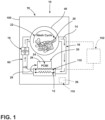
FIG. 1 is a schematic diagram illustrating an aspect of a laundry appliance that incorporates a phase change material within an airflow path; -
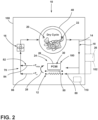
FIG. 2 is a schematic diagram illustrating an appliance that incorporates an aspect of the thermal storage mechanism that is in thermal communication with a plurality of branches of an airflow path for the appliance; -
FIG. 3 is a linear flow diagram illustrating a method for heating process air for drying articles within a laundry appliance; and -
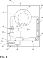
FIG. 4 is a schematic diagram illustrating an aspect of a laundry appliance that incorporates a phase change material within a secondary condenser. - The components in the figures are not necessarily to scale, emphasis instead being placed upon illustrating the principles described herein.
- The present illustrated embodiments reside primarily in combinations of method steps and apparatus components related to apparatus components related to a thermal storage mechanism that captures thermal energy produced by one or more heat sources, where heat that is not directed into process air for an airflow path is captured within the thermal storage mechanism for subsequent use within the same laundry cycle or a separate laundry cycle. Accordingly, the apparatus components and method steps have been represented, where appropriate, by conventional symbols in the drawings, showing only those specific details that are pertinent to understanding the embodiments of the present disclosure so as not to obscure the disclosure with details that will be readily apparent to those of ordinary skill in the art having the benefit of the description herein. Further, like numerals in the description and drawings represent like elements.
- For purposes of description herein, the terms "upper," "lower," "right," "left," "rear," "front," "vertical," "horizontal," and derivatives thereof shall relate to the disclosure as oriented in
FIG. 1 . Unless stated otherwise, the term "front" shall refer to the surface of the element closer to an intended viewer, and the term "rear" shall refer to the surface of the element further from the intended viewer. However, it is to be understood that the disclosure may assume various alternative orientations, except where expressly specified to the contrary. It is also to be understood that the specific devices and processes illustrated in the attached drawings, and described in the following specification are simply exemplary embodiments of the inventive concepts defined in the appended claims. Hence, specific dimensions and other physical characteristics relating to the embodiments disclosed herein are not to be considered as limiting, unless the claims expressly state otherwise. - The terms "including," "comprises," "comprising," or any other variation thereof, are intended to cover a non-exclusive inclusion, such that a process, method, article, or apparatus that comprises a list of elements does not include only those elements but may include other elements not expressly listed or inherent to such process, method, article, or apparatus. An element proceeded by "comprises a ... " does not, without more constraints, preclude the existence of additional identical elements in the process, method, article, or apparatus that comprises the element.
- Referring to
FIGS. 1 ,2 and4 ,reference numeral 10 generally refers to a laundry appliance, typically a dryer, a laundry appliance having a drying capability, or other heating, cooling or dehumidifying appliance. Included within thelaundry appliance 10 is a heating assembly that includes one ormore heaters 12 that are used to heatprocess air 14 that is delivered by ablower 16 through anairflow path 18 for dryingarticles 20 within aprocessing space 22. Thethermal storage mechanism 24 typically includes aphase change material 26 that can receivethermal energy 28, or heat, from one of theheaters 12 and store thatthermal energy 28 for an extended period of time. - This stored
thermal energy 28 can be used later within the same laundry cycle or within a subsequent laundry cycle. According to various aspects of the device, thelaundry appliance 10 includes theblower 16 that directs theprocess air 14 through theairflow path 18. A rotatingdrum 40 defines theprocessing space 22 and holdsarticles 20 to be processed. Anouter cabinet 100 surrounds thedrum 40. Typically, processingarticles 20 includes dryingarticles 20 that have been washed or otherwise treated within thesame appliance 10 or aseparate washing appliance 10. Aheater 12 is positioned in thermal communication with theairflow path 18. Thisheater 12 providesthermal energy 28 to theprocess air 14 and elevates the temperature of theprocess air 14 for use in drying thearticles 20 within theprocessing space 22. - In at least one aspect of the device, the
primary heater 12 is in the form of a condenser of a heat exchange system, such as a heat pump system. Typically, a heat pump system includes a condenser and an evaporator, where the evaporator absorbsthermal energy 28 to cool and dehumidify theprocess air 14 that is delivered from thedrum 40. After this dehumidification occurs, theprocess air 14 is delivered by or through the condenser. The condenser rejectsthermal energy 28 and delivers this rejectedthermal energy 28 to theprocess air 14 for delivery back to theprocessing space 22. Thethermal storage mechanism 24 includes thephase change material 26. Thisphase change material 26 retainsthermal energy 28 from the condenser that has not been directed into theprocess air 14. Stated another way, thethermal energy 28 captured by thephase change material 26 is in the form of heat that would dissipate, be lost, wasted, or would otherwise not be used within a drying operation of theappliance 10. The capturedheat 30 stored within thephase change material 26 is kept for an extended period of time. The storedthermal energy 28 can then be utilized during a subsequent laundry cycle or a subsequent portion of the same laundry cycle. - According to various aspects of the device, the
primary heater 12 for theappliance 10 can include the condenser for a heat pump system, a condenser for a condensing dryer, a resistive heating element, a gas-powered heating element, combinations thereof, and other similar heating elements that are used withinlaundry appliances 10. Where theprimary heater 12 is in the form of the condenser for a heat pump system, it is common that asecondary heater 50 is incorporated within thelaundry appliance 10 for providing additionalthermal energy 28 to theprocess air 14 moved through theairflow path 18. Thissecondary heater 50 is in thermal communication with theairflow path 18 as well as thephase change material 26. In this manner, thesecondary heater 50 can provide heat directly to theprocess air 14 for elevating the temperature of theprocess air 14 to be used within a current laundry cycle. Additionally, excessthermal energy 28 generated by thesecondary heater 50 can be captured within thephase change material 26 for later use. It is contemplated that thesecondary heater 50 can be in the form of an electrically resistive heating element or a gas-powered heater. Additionally, thesecondary heater 50 can be positioned adjacent to theprimary heater 12 or can be positioned downstream from theprimary heater 12. In either instance, thesecondary heater 50 and theprimary heater 12 are typically positioned adjacent to thephase change material 26. In this manner, thephase change material 26 can obtainthermal energy 28 from theprimary heater 12 and thesecondary heater 50 to prevent a loss ofthermal energy 28 from theappliance 10. - According to various aspects of the device, as exemplified in
FIGS. 1 and2 , theairflow path 18 can include asingle air duct 60 that moves through theappliance 10 between theprocessing space 22 within thedrum 40 and thethermal storage mechanism 24. As discussed herein, thethermal storage mechanism 24 can include any one or more of the heaters described herein and a cooling mechanism. This cooling mechanism can be in the form of an evaporator, air-to-air heat exchanger, or other similar mechanism for extractingthermal energy 28 from theprocess air 14. Where theairflow path 18 includes asingle air duct 60, the various heaters and thephase change material 26 are each positioned in communication with theairflow path 18. Additionally, thephase change material 26 is placed in thermal communication with each of the heaters, theprimary heater 12 and thesecondary heater 50, for capturingthermal energy 28 that is not directly used for elevating the temperature of theprocess air 14. - Use of the captured
heat 30 within thephase change material 26 typically occurs where additionalthermal energy 28 is needed for accomplishing a particular laundry function. Such a laundry function can include a quick-dry cycle 70. In a quick-dry cycle 70, theprocess air 14 is heated to a higher temperature that is typically not achievable using theprimary heater 12 and thesecondary heater 50. Using this higher temperature, greater amounts of moisture from within theprocessing space 22 can be captured by theprocess air 14 moving through thedrum 40. In turn, the higher temperature of theprocess air 14 typically results in a lower time needed for drying thearticles 20 within thedrum 40. To achieve this elevated temperature, thephase change material 26, having capturedthermal energy 28 from a previous laundry cycle or previous portion of the current laundry cycle releases this capturedheat 30 into theprocess air 14. This release of capturedheat 30 can be combined with the heat generated from the heating assembly for providing a combined heat that achieves the desired temperature of theprocess air 14 to perform the quick-dry cycle 70. - The
phase change material 26 can also use the capturedheat 30 for use during a start-up function. The additional heat may be needed in anappliance 10 having a heat pump system. Certain heat pump systems require a certain amount of time for the condenser to achieve a desired thermal output. As the condenser achieves the desired thermal output, capturedheat 30 from thephase change material 26 can be utilized for adding heat and increasing the temperature of theprocess air 14 at the beginning of a particular laundry cycle. Typically, capturedheat 30 within thephase change material 26 will be used within laundry cycles that require a higher than normal temperature of theprocess air 14. - Referring now to
FIG. 2 , theairflow path 18 can include separate branches that move through thethermal storage mechanism 24 for theappliance 10. Aprimary branch 80 can move past theprimary heater 12 as well as asecondary heater 50. Thisprimary branch 80 of theairflow path 18 is typically used in each of the laundry cycles performed by theappliance 10. Thephase change material 26 can also be positioned adjacent to theprimary branch 80 of theairflow path 18 for receiving excessthermal energy 28 from the various heat sources of theappliance 10. Theairflow path 18 can also include asecondary branch 82 that is positioned adjacent to thephase change material 26. Thesecondary branch 82 can be utilized during the quick-dry cycle 70 for deliveringprocess air 14 past or through thephase change material 26. During this operation, capturedheat 30 within thephase change material 26 is delivered into anaccessory flow 84 ofprocess air 14 to be combined with aprimary flow 86 ofprocess air 14 that moves through theprimary branch 80 of theairflow path 18. - The combination of the
primary flow 86 ofprocess air 14 that is heated by theprimary heater 12 and, in certain instances, asecondary heater 50, is combined with the secondary flow ofprocess air 14 that is heated by receivingthermal energy 28 from thephase change material 26. This combination of theprimary flow 86 ofprocess air 14 and theaccessory flow 84 ofprocess air 14 results in the higher temperature of theprocess air 14 that can be delivered to theprocessing space 22 within thedrum 40 during the quick-dry cycle 70 and other high-heat demand situations. Various baffles, air handlers, and other air directing devices can be utilized for providing theaccessory flow 84 ofprocess air 14 through thesecondary branch 82 of theairflow path 18 and through thephase change material 26. - In such an aspect of the device, as exemplified in
FIG. 2 , where only theprimary branch 80 of theairflow path 18 is utilized, theprimary heater 12 and thesecondary heater 50 each operate to heat theprocess air 14. As discussed herein, excessthermal energy 28 produced by theprimary heater 12 and thesecondary heater 50 is captured by thephase change material 26. Storage of this capturedheat 30 within thephase change material 26 can be utilized for heating theaccessory flow 84 ofprocess air 14 within thesecondary branch 82 of theairflow path 18. It is also contemplated that thephase change material 26 can be utilized for heating theprimary flow 86 ofprocess air 14 through theprimary branch 80. In each of the instances described herein, thethermal energy 28 stored by thephase change material 26 is utilized for increasing the temperature of theprocess air 14. Use of thephase change material 26 can result in theappliance 10 being fitted with heating elements of slightly diminished size due to the more efficient use and storage ofthermal energy 28 produced by each of theprimary heater 12, thesecondary heater 50, and other heating mechanisms that are incorporated into theappliance 10. Additionally, by capturing excessthermal energy 28, thephase change material 26 can be used for decreasing the time needed for dryingarticles 20 within thedrum 40. - According to various aspects of the device, the
phase change material 26 can be located within thethermal storage mechanism 24 for theappliance 10. Thisthermal storage mechanism 24 can be positioned within thecabinet 100 and near the various heaters for heating theprocess air 14. It is also contemplated that thethermal storage mechanism 24 can be aseparate module 102 that is positioned adjacent to and exterior to thecabinet 100 for theappliance 10. In such an aspect of the device, theairflow path 18 can be configured to move from within thecabinet 100, through a wall of thecabinet 100 and to an area outside of thecabinet 100 and through themodule 102 containing thethermal storage mechanism 24, and then back through the wall and into thecabinet 100 for delivery to theprocessing space 22 within thedrum 40. Where thethermal storage mechanism 24 is an external module, this external module can be in the form of a factory-installed module or an aftermarket module that can be installed after purchase. - According to various aspects of the device, the
thermal storage mechanism 24 can be used in combination with asingle drying appliance 10, as well as withinmultiple appliances 10. In such an aspect of the device, thethermal storage mechanism 24 can be attached to one or more heaters of a washer and dryer pair where excessthermal energy 28 produced by theseappliances 10 can be gathered within thephase change material 26 of thethermal storage mechanism 24 as capturedheat 30. In such an aspect, capturedheat 30 within thephase change material 26 can be utilized for heating fluid materials (liquid and/or gas) within either of the washer or the dryer. Additionally, where theappliance 10 is a combination washing and dryingappliance 10, thephase change material 26 can be utilized for storing capturedheat 30 from the various heaters within theappliance 10. As described herein, the capturedheat 30 retained by thephase change material 26 can be utilized for washing and drying phases of a particular laundry cycle. - In various aspects of the device, as exemplified in
FIG. 4 , anappliance 10 that incorporates the heat exchange system, such as a heat pump system or a condensing system, can include a cooler, such as anevaporator 108, for extracting heat from theprocess air 14. This extraction of heat is utilized for dehumidifying theprocess air 14 after it leaves theprocessing space 22. By extracting heat from theprocess air 14, moisture is also condensed from theprocess air 14. The now cooled and dehumidified air can then be returned to the condenser, being theprimary heater 12 for the system, or other heating mechanism, as described herein. Theprocess air 14 is reheated using theprimary heater 12 and is returned to thedrum 40. To provide increased heating, theappliance 10 can include asecondary heater 50 that is positioned downstream of theprimary heater 12 along the process air flow direction. - Referring again to
FIG. 4 , to assist in the rejection ofthermal energy 28 from theprimary heater 12 and the transfer ofthermal energy 28 into theprocess air 14 by theprimary heater 12,certain appliances 10 can include asecondary condenser 110 that rejects additional amount ofthermal energy 28 that cannot be delivered into theprocess air 14.Thermal energy 28, typically from a refrigerant or other heat exchange media, is delivered through each of theprimary heater 12 and thesecondary condenser 110 to reject a sufficient amount ofthermal energy 28. This use of theprimary heater 12 and thesecondary condenser 110 accounts for a proper balance of the system to provide for a consistent exchange ofthermal energy 28 between theprocess air 14 and theevaporator 108 and theprimary heater 12 and thesecondary condenser 110. - Referring again to
FIG. 4 , a portion of thephase change material 26 can be positioned around thesecondary condenser 110 for receiving this additionally extractedthermal energy 28. This extractedthermal energy 28 can be utilized, as described herein, for other portions of the laundry cycle or subsequent laundry cycles. In certain aspects of the device, thesecondary condenser 110 can be used to reject or expel additional amounts ofthermal energy 28. This rejection ofthermal energy 28 is useful for preventing overheating of the systems within theappliance 10. It is contemplated that this rejectedthermal energy 28 can be captured within a portion of thephase change material 26 that is positioned adjacent to thesecondary condenser 110. In this aspect of the device, thephase change material 26 receives the rejectedthermal energy 28 from thesecondary condenser 110 for later use. During a later laundry cycle, the capturedheat 30 within thephase change material 26 can be transferred back into the refrigerant moving through a refrigerant loop that includes thesecondary condenser 110. In this manner, thephase change material 26 transfers thethermal energy 28 back into the refrigerant and the now charged refrigerant is delivered to the primary condenser orprimary heater 12 to be delivered into theprocess air 14 moving through theairflow path 18. In certain aspects of the device, it is contemplated that thethermal energy 28 that is received and stored within thephase change material 26 as capturedheat 30 can be delivered, via an alternative path, back into theprocess air 14 moving through theairflow path 18. - According to the various aspects of the device, as exemplified in
FIGS 1-4 , thephase change material 26 receivesthermal energy 28, typically excessthermal energy 28, from theprimary heater 12 and thesecondary heater 50 to define capturedheat 30. This capturedheat 30 can be stored and utilized later in the laundry cycle or within the subsequent laundry cycle. Acontroller 112 for theappliance 10 can be placed in communication with theevaporator 108, theprimary heater 12, thesecondary condenser 110, thesecondary heater 50 and theblower 16, along with other components of theappliance 10. In this manner, thecontroller 112 can operate these components to allow for the efficient exchange ofthermal energy 28 for operating theappliance 10. - The
phase change material 26 can be in the form of any one of various materials. Such materials can include, but are not limited to, glycol, paraffin wax, a refrigerant, water, air, combinations thereof, and other similar materials that can be used to absorb and storethermal energy 28 for a period of time. - Having described various aspects of the device, a method 400 is disclosed for operating a
laundry appliance 10 utilizing athermal storage mechanism 24. According to the method 400,step 402 includes activating a laundry cycle. Step 404 includes activating one or more heaters within theappliance 10 forheating process air 14. Step 406 includes capturing excessthermal energy 28 within aphase change material 26 to define capturedheat 30. Step 408 includes storing the capturedheat 30 for a period of time. Step 410 includes activating a quick-dry cycle 70. Step 412 includes directingprocess air 14 in thermal communication with thephase change material 26 to receive the capturedheat 30 and increase the temperature of theprocess air 14. As described herein, the capturedheat 30 can be delivered from thephase change material 26 and to theprocess air 14 either directly through thermal communication, or indirectly through the use of a refrigerant within a refrigerant loop. As described herein, the quick-dry cycle 70 utilizes the one or more heaters to directly heat theprocess air 14 that is delivered to theprocessing space 22 of theappliance 10. The capturedheat 30 within thephase change material 26 is also directed into theprocess air 14 for elevating the temperature of theprocess air 14. - In certain aspects of the device, the
phase change material 26 may be located upstream of theprimary heater 12 and/or thesecondary heater 50 to provide a greater temperature difference between the temperature of theprocess air 14 and the temperature of thephase change material 26 having the capturedheat 30. Where there is a greater difference between the temperature of theprocess air 14 and thephase change material 26, a greater exchange ofthermal energy 28 can occur. This initial elevation of the temperature of theprocess air 14 can be followed by theprocess air 14 moving past theprimary heater 12 and/or thesecondary heater 50 for providing a greater increase in temperature of theprocess air 14 as it moves toward theprocessing space 22. - In certain aspects of the device, it is also contemplated that the
phase change material 26 can be located downstream of the various heaters and also adjacent to the various heaters. - The invention disclosed herein is further summarized in the following paragraphs and is further characterized by combinations of any and all of the various aspects described therein.
- According to an aspect of the present disclosure, a laundry appliance includes a blower that directs process air through an airflow path. A rotating drum holds articles to be processed. A heat pump system has a condenser and an evaporator. The evaporator dehumidifies the process air that is delivered from the drum and the condenser heats the process air that is delivered from the evaporator. A phase change material retains heat from the condenser that is directed away from the process air to define captured heat, and the captured heat of the phase change material is utilized during a subsequent laundry cycle.
- According to another aspect, the airflow path includes a single duct that extends between a processing space within the rotating drum and the heat pump system.
- According to another aspect, the laundry appliance further includes a secondary heater that is positioned adjacent to the phase change material. The secondary heater is in thermal communication with the phase change material and the airflow path.
- According to another aspect, the captured heat is utilizing during one of a quick-start function of the subsequent laundry cycle and a quick-dry function of the subsequent drying cycle.
- According to another aspect, the airflow path proximate the phase change material includes a primary branch and a secondary branch. The secondary branch is utilized for delivering the captured heat from the phase change material to the airflow path via the secondary branch.
- According to another aspect, the primary branch is continuously used during operation of the blower.
- According to another aspect, the phase change material includes at least one of glycol, paraffin wax, and a refrigerant.
- According to another aspect, the laundry appliance further includes a secondary condenser. The phase change material is positioned adjacent to the secondary condenser for receiving heat from the secondary condenser to define the captured heat. The captured heat is delivered to the airflow path during the subsequent laundry cycle.
- According to another aspect, the secondary condenser is in thermal communication with the airflow path via a refrigerant.
- According to another aspect, operation of the condenser and the secondary heater are operated using a controller.
- According to another aspect, the phase change material is positioned upstream of the condenser.
- According to another aspect, the phase change material is disposed within a module that is positioned exterior to a structural cabinet that surrounds the rotating drum.
- According to another aspect, the airflow path extends through a wall of the structural cabinet to move through the module having the phase change material, and the module includes the secondary heater.
- According to another aspect, the phase change material is also in thermal communication with a separate laundry appliance that includes a washing function.
- According to another aspect of the present disclosure, a laundry appliance includes a blower that directs process air through an airflow path. A rotating drum holds articles to be processed. A heat exchange system has a heating assembly. A heating assembly generates heat that is delivered into the process air from a processing space defined within the rotating drum. A phase change material retains heat from the heating assembly that is directed away from the process air to define captured heat, and the captured heat of the phase change material is utilized during a subsequent laundry cycle.
- According to another aspect, during the subsequent laundry cycle, the captured heat from the phase change material and heat from the heating assembly cooperate to deliver a combined heat to the process air.
- According to another aspect, the heating assembly includes an electrically resistive heating element.
- According to another aspect, the heating assembly includes a condenser.
- According to another aspect, the heating assembly includes a primary heater in communication with the airflow path that delivers the process air, and the heating assembly also includes a secondary heater that is in communication with the airflow path and the phase change material.
- According to yet another aspect of the present disclosure, a method for operating a laundry appliance includes the steps of activating a blower that delivers process air through an airflow path, activating at least one heater that is in thermal communication with the airflow path wherein heat from the at least one heater is delivered into the airflow path, capturing excess thermal energy from the at least one heater within a phase change material to define captured heat, storing the captured heat for a period of time, activating a subsequent drying cycle, and delivering process air into thermal communication with the phase change material to transfer the captured heat from the phase change material to the process air for increasing a temperature of the process air.
Claims (15)
- A laundry appliance (10) comprising:a blower (16) that directs process air (14) through an airflow path (18);a rotating drum (40) that holds articles (20) to be processed;a heat pump system (12) having a condenser and an evaporator, wherein the evaporator dehumidifies the process air (14) delivered from the drum (40) and wherein the condenser heats the process air (14) delivered from the evaporator; anda phase change material (26) configured to retain heat (30) from the condenser that is directed away from the process air (14) to define captured heat (30), and to release the captured heat (30) of the phase change material (26) during a subsequent laundry cycle.
- The laundry appliance (10) of claim 1, wherein the airflow path (18) includes a single duct (60) that extends between a processing space (22) within the rotating drum (40) and the heat pump system (12).
- The laundry appliance (10) of any one of claims 1-2, further comprising a secondary heater (50) that is positioned adjacent to the phase change material (26), wherein the secondary heater (50) is in thermal communication with the phase change material (26) and the airflow path (18).
- The laundry appliance (10) of any one of claims 1-3, configured to release the captured heat (30) during one of a quick-start function of the subsequent laundry cycle and a quick-dry function of the subsequent drying cycle (70).
- The laundry appliance (10) of any one of claims 1-4, wherein the airflow path (18) proximate the phase change material (26) includes a primary branch (80) and a secondary branch (82), wherein the secondary branch (82) is configured for delivering the captured heat (30) from the phase change material (26) to the airflow path (18).
- The laundry appliance (10) of claim 5, wherein the primary branch (80) is continuously used during operation of the blower (16).
- The laundry appliance (10) of any one of claims 1-6, wherein the phase change material (26) includes at least one of glycol, paraffin wax, and a refrigerant.
- The laundry appliance (10) of any one of claims 1-7, further comprising a secondary condenser (110), wherein the phase change material (26) is positioned adjacent to the secondary condenser (110) for receiving heat from the secondary condenser (110) to define the captured heat (30), and wherein the captured heat (30) is delivered to the airflow path (18) during the subsequent laundry cycle.
- The laundry appliance (10) of claim 8, wherein the secondary condenser (110) is in thermal communication with the airflow path (18) via a refrigerant.
- The laundry appliance (10) of any one of claims 3-9, wherein operation of the condenser and the secondary heater (50) are operated using a controller (112).
- The laundry appliance (10) of any one of claims 3-10, wherein the phase change material (26) is positioned upstream of the condenser.
- The laundry appliance (10) of claim 11, wherein the phase change material (26) is placed within a module (102) that is positioned exterior to a structural cabinet (100) that surrounds the rotating drum (40).
- The laundry appliance (10) of claim 12, wherein the airflow path (18) extends through a wall of the structural cabinet (100) to move through the module (102) having the phase change material (26), wherein the module (102) includes the secondary heater (50).
- The laundry appliance (10) of any one of claims 1-13, wherein the phase change material (26) is also in thermal communication with a separate laundry appliance (10) that includes a washing function.
- A method (400) for operating the laundry appliance (10) of any one of claims 1-14, the method (400) comprising steps of:activating the blower (16) that delivers the process air (14) through the airflow path (18);activating a condenser of the heat pump system (12) that is in thermal communication with the airflow path (18) wherein heat from the condenser is delivered into the airflow path (18);capturing excess thermal energy (28) from the condenser within the phase change material (26) to define the captured heat (30);storing the captured heat (30) for a period of time;activating the subsequent drying cycle (70); anddelivering the process air (14) into thermal communication with the phase change material (26) to transfer the captured heat (30) from the phase change material (26) to the process air (14) for increasing a temperature of the process air (14).
Applications Claiming Priority (2)
| Application Number | Priority Date | Filing Date | Title |
|---|---|---|---|
| US202263312127P | 2022-02-21 | 2022-02-21 | |
| US18/151,732 US20230265598A1 (en) | 2022-02-21 | 2023-01-09 | Laundry appliance having a thermal storage mechanism for capturing excess heat from one or more heat sources |
Publications (1)
| Publication Number | Publication Date |
|---|---|
| EP4230787A1 true EP4230787A1 (en) | 2023-08-23 |
Family
ID=85202201
Family Applications (1)
| Application Number | Title | Priority Date | Filing Date |
|---|---|---|---|
| EP23155695.2A Withdrawn EP4230787A1 (en) | 2022-02-21 | 2023-02-08 | Laundry appliance that utilizes thermal storage mechanism and method for operating the same |
Country Status (2)
| Country | Link |
|---|---|
| US (1) | US20230265598A1 (en) |
| EP (1) | EP4230787A1 (en) |
Cited By (1)
| Publication number | Priority date | Publication date | Assignee | Title |
|---|---|---|---|---|
| US20230265600A1 (en) * | 2022-02-21 | 2023-08-24 | Whirlpool Corporation | Thermal storage mechanism for a laundry appliance that utilizes recovery heat and renewable energy sources |
Citations (5)
| Publication number | Priority date | Publication date | Assignee | Title |
|---|---|---|---|---|
| US20090300941A1 (en) * | 2006-12-22 | 2009-12-10 | BSH Bosch und Siemens Hausgeräte GmbH | Household appliance and method for drying a damp item |
| US20110252835A1 (en) * | 2009-08-18 | 2011-10-20 | Whirlpool Corporation | Heat pump (server) coupled washer and dryer pair |
| US20110277334A1 (en) * | 2010-04-28 | 2011-11-17 | Lee Yongju | Cloth treating apparatus |
| US20140310976A1 (en) * | 2013-04-23 | 2014-10-23 | Whirlpool Corporation | Dryer or washer dryer and method for this operation |
| US20150013178A1 (en) * | 2012-02-21 | 2015-01-15 | BSH Bosch und Siemens Hausgeräte GmbH | Household appliance, more particularly a tumble dryer, comprising a latent heat store, and method for the operation thereof |
-
2023
- 2023-01-09 US US18/151,732 patent/US20230265598A1/en active Pending
- 2023-02-08 EP EP23155695.2A patent/EP4230787A1/en not_active Withdrawn
Patent Citations (5)
| Publication number | Priority date | Publication date | Assignee | Title |
|---|---|---|---|---|
| US20090300941A1 (en) * | 2006-12-22 | 2009-12-10 | BSH Bosch und Siemens Hausgeräte GmbH | Household appliance and method for drying a damp item |
| US20110252835A1 (en) * | 2009-08-18 | 2011-10-20 | Whirlpool Corporation | Heat pump (server) coupled washer and dryer pair |
| US20110277334A1 (en) * | 2010-04-28 | 2011-11-17 | Lee Yongju | Cloth treating apparatus |
| US20150013178A1 (en) * | 2012-02-21 | 2015-01-15 | BSH Bosch und Siemens Hausgeräte GmbH | Household appliance, more particularly a tumble dryer, comprising a latent heat store, and method for the operation thereof |
| US20140310976A1 (en) * | 2013-04-23 | 2014-10-23 | Whirlpool Corporation | Dryer or washer dryer and method for this operation |
Cited By (1)
| Publication number | Priority date | Publication date | Assignee | Title |
|---|---|---|---|---|
| US20230265600A1 (en) * | 2022-02-21 | 2023-08-24 | Whirlpool Corporation | Thermal storage mechanism for a laundry appliance that utilizes recovery heat and renewable energy sources |
Also Published As
| Publication number | Publication date |
|---|---|
| US20230265598A1 (en) | 2023-08-24 |
Similar Documents
| Publication | Publication Date | Title |
|---|---|---|
| US10907297B2 (en) | Closed cycle condenser dryer with heat regeneration | |
| US9803313B2 (en) | Clothes treating apparatus | |
| EP2550390B1 (en) | Clothes dryer | |
| US9146056B2 (en) | Laundry treating apparatus having expansion valve which is variable according to the driving mode | |
| EP0999302B1 (en) | Tumble dryer with a heat pump | |
| US9207015B2 (en) | Dryer having evaporator equipped with second condenser | |
| US20090293301A1 (en) | Device and Method for Drying Laundry | |
| CN101849061A (en) | Household appliance having a heat pump unit and means for cooling a component thereof | |
| US20090165328A1 (en) | Dryer, set up for operation drawing of electric power, and method for operating it | |
| EP3379992B1 (en) | Household appliance with a heat pump and method for operating a household appliance | |
| WO2012072226A9 (en) | Method of operating a heat pump dryer and heat pump dryer | |
| WO2012072625A2 (en) | Method of operating a heat pump dryer and heat pump dryer | |
| EP3117166B1 (en) | Closed-cycle condenser dryer with heat regeneration | |
| EP3256635B1 (en) | Clothes dryer and method for operating a clothes dryer | |
| WO2014146953A1 (en) | Laundry treatment apparatus with heat pump | |
| US20230265598A1 (en) | Laundry appliance having a thermal storage mechanism for capturing excess heat from one or more heat sources | |
| EP2692940A1 (en) | Method for drying laundry in a laundry drying machine and laundry drying machine | |
| EP2549007B1 (en) | Heat pump laundry treatment apparatus | |
| EP2655726B1 (en) | Heat pump laundry dryer | |
| US20260015785A1 (en) | Thermal exchange system for an appliance | |
| EP2650425B1 (en) | Laundry drying machine | |
| EP2366828B1 (en) | Laundry dryer machine with improved condenser cooling system | |
| NL8004618A (en) | DRIER. | |
| EP2716807A1 (en) | A heat pump laundry drying machine and a method for operating a heat pump laundry drying machine | |
| KR102348960B1 (en) | A Laundry treating apparatus comprising a heat pump and control method of the same. |
Legal Events
| Date | Code | Title | Description |
|---|---|---|---|
| PUAI | Public reference made under article 153(3) epc to a published international application that has entered the european phase |
Free format text: ORIGINAL CODE: 0009012 |
|
| STAA | Information on the status of an ep patent application or granted ep patent |
Free format text: STATUS: THE APPLICATION HAS BEEN PUBLISHED |
|
| AK | Designated contracting states |
Kind code of ref document: A1 Designated state(s): AL AT BE BG CH CY CZ DE DK EE ES FI FR GB GR HR HU IE IS IT LI LT LU LV MC ME MK MT NL NO PL PT RO RS SE SI SK SM TR |
|
| STAA | Information on the status of an ep patent application or granted ep patent |
Free format text: STATUS: REQUEST FOR EXAMINATION WAS MADE |
|
| 17P | Request for examination filed |
Effective date: 20240223 |
|
| RBV | Designated contracting states (corrected) |
Designated state(s): AL AT BE BG CH CY CZ DE DK EE ES FI FR GB GR HR HU IE IS IT LI LT LU LV MC ME MK MT NL NO PL PT RO RS SE SI SK SM TR |
|
| GRAP | Despatch of communication of intention to grant a patent |
Free format text: ORIGINAL CODE: EPIDOSNIGR1 |
|
| STAA | Information on the status of an ep patent application or granted ep patent |
Free format text: STATUS: GRANT OF PATENT IS INTENDED |
|
| INTG | Intention to grant announced |
Effective date: 20241219 |
|
| STAA | Information on the status of an ep patent application or granted ep patent |
Free format text: STATUS: THE APPLICATION IS DEEMED TO BE WITHDRAWN |
|
| 18D | Application deemed to be withdrawn |
Effective date: 20250423 |