EP4230773A1 - Anode for alkaline water electrolysis and method for producing same - Google Patents
Anode for alkaline water electrolysis and method for producing same Download PDFInfo
- Publication number
- EP4230773A1 EP4230773A1 EP21880201.5A EP21880201A EP4230773A1 EP 4230773 A1 EP4230773 A1 EP 4230773A1 EP 21880201 A EP21880201 A EP 21880201A EP 4230773 A1 EP4230773 A1 EP 4230773A1
- Authority
- EP
- European Patent Office
- Prior art keywords
- nickel
- water electrolysis
- alkaline water
- electrically conductive
- anode
- Prior art date
- Legal status (The legal status is an assumption and is not a legal conclusion. Google has not performed a legal analysis and makes no representation as to the accuracy of the status listed.)
- Granted
Links
Images


Classifications
-
- C—CHEMISTRY; METALLURGY
- C25—ELECTROLYTIC OR ELECTROPHORETIC PROCESSES; APPARATUS THEREFOR
- C25B—ELECTROLYTIC OR ELECTROPHORETIC PROCESSES FOR THE PRODUCTION OF COMPOUNDS OR NON-METALS; APPARATUS THEREFOR
- C25B11/00—Electrodes; Manufacture thereof not otherwise provided for
- C25B11/04—Electrodes; Manufacture thereof not otherwise provided for characterised by the material
- C25B11/051—Electrodes formed of electrocatalysts on a substrate or carrier
- C25B11/073—Electrodes formed of electrocatalysts on a substrate or carrier characterised by the electrocatalyst material
- C25B11/075—Electrodes formed of electrocatalysts on a substrate or carrier characterised by the electrocatalyst material consisting of a single catalytic element or catalytic compound
- C25B11/077—Electrodes formed of electrocatalysts on a substrate or carrier characterised by the electrocatalyst material consisting of a single catalytic element or catalytic compound the compound being a non-noble metal oxide
- C25B11/0773—Electrodes formed of electrocatalysts on a substrate or carrier characterised by the electrocatalyst material consisting of a single catalytic element or catalytic compound the compound being a non-noble metal oxide of the perovskite type
-
- C—CHEMISTRY; METALLURGY
- C25—ELECTROLYTIC OR ELECTROPHORETIC PROCESSES; APPARATUS THEREFOR
- C25B—ELECTROLYTIC OR ELECTROPHORETIC PROCESSES FOR THE PRODUCTION OF COMPOUNDS OR NON-METALS; APPARATUS THEREFOR
- C25B11/00—Electrodes; Manufacture thereof not otherwise provided for
- C25B11/04—Electrodes; Manufacture thereof not otherwise provided for characterised by the material
-
- B—PERFORMING OPERATIONS; TRANSPORTING
- B01—PHYSICAL OR CHEMICAL PROCESSES OR APPARATUS IN GENERAL
- B01J—CHEMICAL OR PHYSICAL PROCESSES, e.g. CATALYSIS OR COLLOID CHEMISTRY; THEIR RELEVANT APPARATUS
- B01J23/00—Catalysts comprising metals or metal oxides or hydroxides, not provided for in group B01J21/00
- B01J23/70—Catalysts comprising metals or metal oxides or hydroxides, not provided for in group B01J21/00 of the iron group metals or copper
- B01J23/76—Catalysts comprising metals or metal oxides or hydroxides, not provided for in group B01J21/00 of the iron group metals or copper combined with metals, oxides or hydroxides provided for in groups B01J23/02 - B01J23/36
- B01J23/84—Catalysts comprising metals or metal oxides or hydroxides, not provided for in group B01J21/00 of the iron group metals or copper combined with metals, oxides or hydroxides provided for in groups B01J23/02 - B01J23/36 with arsenic, antimony, bismuth, vanadium, niobium, tantalum, polonium, chromium, molybdenum, tungsten, manganese, technetium or rhenium
- B01J23/889—Manganese, technetium or rhenium
-
- B—PERFORMING OPERATIONS; TRANSPORTING
- B01—PHYSICAL OR CHEMICAL PROCESSES OR APPARATUS IN GENERAL
- B01J—CHEMICAL OR PHYSICAL PROCESSES, e.g. CATALYSIS OR COLLOID CHEMISTRY; THEIR RELEVANT APPARATUS
- B01J37/00—Processes, in general, for preparing catalysts; Processes, in general, for activation of catalysts
- B01J37/02—Impregnation, coating or precipitation
-
- B—PERFORMING OPERATIONS; TRANSPORTING
- B01—PHYSICAL OR CHEMICAL PROCESSES OR APPARATUS IN GENERAL
- B01J—CHEMICAL OR PHYSICAL PROCESSES, e.g. CATALYSIS OR COLLOID CHEMISTRY; THEIR RELEVANT APPARATUS
- B01J37/00—Processes, in general, for preparing catalysts; Processes, in general, for activation of catalysts
- B01J37/08—Heat treatment
-
- B—PERFORMING OPERATIONS; TRANSPORTING
- B01—PHYSICAL OR CHEMICAL PROCESSES OR APPARATUS IN GENERAL
- B01J—CHEMICAL OR PHYSICAL PROCESSES, e.g. CATALYSIS OR COLLOID CHEMISTRY; THEIR RELEVANT APPARATUS
- B01J37/00—Processes, in general, for preparing catalysts; Processes, in general, for activation of catalysts
- B01J37/12—Oxidising
- B01J37/14—Oxidising with gases containing free oxygen
-
- C—CHEMISTRY; METALLURGY
- C25—ELECTROLYTIC OR ELECTROPHORETIC PROCESSES; APPARATUS THEREFOR
- C25B—ELECTROLYTIC OR ELECTROPHORETIC PROCESSES FOR THE PRODUCTION OF COMPOUNDS OR NON-METALS; APPARATUS THEREFOR
- C25B1/00—Electrolytic production of inorganic compounds or non-metals
- C25B1/01—Products
- C25B1/02—Hydrogen or oxygen
- C25B1/04—Hydrogen or oxygen by electrolysis of water
-
- C—CHEMISTRY; METALLURGY
- C25—ELECTROLYTIC OR ELECTROPHORETIC PROCESSES; APPARATUS THEREFOR
- C25B—ELECTROLYTIC OR ELECTROPHORETIC PROCESSES FOR THE PRODUCTION OF COMPOUNDS OR NON-METALS; APPARATUS THEREFOR
- C25B11/00—Electrodes; Manufacture thereof not otherwise provided for
- C25B11/04—Electrodes; Manufacture thereof not otherwise provided for characterised by the material
- C25B11/051—Electrodes formed of electrocatalysts on a substrate or carrier
- C25B11/052—Electrodes comprising one or more electrocatalytic coatings on a substrate
-
- C—CHEMISTRY; METALLURGY
- C25—ELECTROLYTIC OR ELECTROPHORETIC PROCESSES; APPARATUS THEREFOR
- C25B—ELECTROLYTIC OR ELECTROPHORETIC PROCESSES FOR THE PRODUCTION OF COMPOUNDS OR NON-METALS; APPARATUS THEREFOR
- C25B11/00—Electrodes; Manufacture thereof not otherwise provided for
- C25B11/04—Electrodes; Manufacture thereof not otherwise provided for characterised by the material
- C25B11/051—Electrodes formed of electrocatalysts on a substrate or carrier
- C25B11/055—Electrodes formed of electrocatalysts on a substrate or carrier characterised by the substrate or carrier material
- C25B11/057—Electrodes formed of electrocatalysts on a substrate or carrier characterised by the substrate or carrier material consisting of a single element or compound
- C25B11/061—Metal or alloy
-
- C—CHEMISTRY; METALLURGY
- C25—ELECTROLYTIC OR ELECTROPHORETIC PROCESSES; APPARATUS THEREFOR
- C25B—ELECTROLYTIC OR ELECTROPHORETIC PROCESSES FOR THE PRODUCTION OF COMPOUNDS OR NON-METALS; APPARATUS THEREFOR
- C25B11/00—Electrodes; Manufacture thereof not otherwise provided for
- C25B11/04—Electrodes; Manufacture thereof not otherwise provided for characterised by the material
- C25B11/051—Electrodes formed of electrocatalysts on a substrate or carrier
- C25B11/073—Electrodes formed of electrocatalysts on a substrate or carrier characterised by the electrocatalyst material
-
- C—CHEMISTRY; METALLURGY
- C25—ELECTROLYTIC OR ELECTROPHORETIC PROCESSES; APPARATUS THEREFOR
- C25B—ELECTROLYTIC OR ELECTROPHORETIC PROCESSES FOR THE PRODUCTION OF COMPOUNDS OR NON-METALS; APPARATUS THEREFOR
- C25B11/00—Electrodes; Manufacture thereof not otherwise provided for
- C25B11/04—Electrodes; Manufacture thereof not otherwise provided for characterised by the material
- C25B11/051—Electrodes formed of electrocatalysts on a substrate or carrier
- C25B11/073—Electrodes formed of electrocatalysts on a substrate or carrier characterised by the electrocatalyst material
- C25B11/075—Electrodes formed of electrocatalysts on a substrate or carrier characterised by the electrocatalyst material consisting of a single catalytic element or catalytic compound
- C25B11/077—Electrodes formed of electrocatalysts on a substrate or carrier characterised by the electrocatalyst material consisting of a single catalytic element or catalytic compound the compound being a non-noble metal oxide
-
- C—CHEMISTRY; METALLURGY
- C25—ELECTROLYTIC OR ELECTROPHORETIC PROCESSES; APPARATUS THEREFOR
- C25B—ELECTROLYTIC OR ELECTROPHORETIC PROCESSES FOR THE PRODUCTION OF COMPOUNDS OR NON-METALS; APPARATUS THEREFOR
- C25B11/00—Electrodes; Manufacture thereof not otherwise provided for
- C25B11/04—Electrodes; Manufacture thereof not otherwise provided for characterised by the material
- C25B11/051—Electrodes formed of electrocatalysts on a substrate or carrier
- C25B11/073—Electrodes formed of electrocatalysts on a substrate or carrier characterised by the electrocatalyst material
- C25B11/091—Electrodes formed of electrocatalysts on a substrate or carrier characterised by the electrocatalyst material consisting of at least one catalytic element and at least one catalytic compound; consisting of two or more catalytic elements or catalytic compounds
-
- C—CHEMISTRY; METALLURGY
- C25—ELECTROLYTIC OR ELECTROPHORETIC PROCESSES; APPARATUS THEREFOR
- C25B—ELECTROLYTIC OR ELECTROPHORETIC PROCESSES FOR THE PRODUCTION OF COMPOUNDS OR NON-METALS; APPARATUS THEREFOR
- C25B9/00—Cells or assemblies of cells; Constructional parts of cells; Assemblies of constructional parts, e.g. electrode-diaphragm assemblies; Process-related cell features
- C25B9/17—Cells comprising dimensionally-stable non-movable electrodes; Assemblies of constructional parts thereof
- C25B9/19—Cells comprising dimensionally-stable non-movable electrodes; Assemblies of constructional parts thereof with diaphragms
- C25B9/23—Cells comprising dimensionally-stable non-movable electrodes; Assemblies of constructional parts thereof with diaphragms comprising ion-exchange membranes in or on which electrode material is embedded
-
- Y—GENERAL TAGGING OF NEW TECHNOLOGICAL DEVELOPMENTS; GENERAL TAGGING OF CROSS-SECTIONAL TECHNOLOGIES SPANNING OVER SEVERAL SECTIONS OF THE IPC; TECHNICAL SUBJECTS COVERED BY FORMER USPC CROSS-REFERENCE ART COLLECTIONS [XRACs] AND DIGESTS
- Y02—TECHNOLOGIES OR APPLICATIONS FOR MITIGATION OR ADAPTATION AGAINST CLIMATE CHANGE
- Y02E—REDUCTION OF GREENHOUSE GAS [GHG] EMISSIONS, RELATED TO ENERGY GENERATION, TRANSMISSION OR DISTRIBUTION
- Y02E60/00—Enabling technologies; Technologies with a potential or indirect contribution to GHG emissions mitigation
- Y02E60/30—Hydrogen technology
- Y02E60/36—Hydrogen production from non-carbon containing sources, e.g. by water electrolysis
-
- Y—GENERAL TAGGING OF NEW TECHNOLOGICAL DEVELOPMENTS; GENERAL TAGGING OF CROSS-SECTIONAL TECHNOLOGIES SPANNING OVER SEVERAL SECTIONS OF THE IPC; TECHNICAL SUBJECTS COVERED BY FORMER USPC CROSS-REFERENCE ART COLLECTIONS [XRACs] AND DIGESTS
- Y02—TECHNOLOGIES OR APPLICATIONS FOR MITIGATION OR ADAPTATION AGAINST CLIMATE CHANGE
- Y02P—CLIMATE CHANGE MITIGATION TECHNOLOGIES IN THE PRODUCTION OR PROCESSING OF GOODS
- Y02P20/00—Technologies relating to chemical industry
- Y02P20/10—Process efficiency
- Y02P20/133—Renewable energy sources, e.g. sunlight
Definitions
- the present invention relates to an alkaline water electrolysis anode and a method for producing the same.
- Hydrogen is secondary energy which is suitable for storage and transportation and has small environmental load, and therefore a hydrogen energy system using hydrogen as an energy carrier has been attracting attention.
- hydrogen is mainly produced by steam reforming of fossil fuel, or the like.
- water electrolysis using renewable energy, such as solar power generation and wind power generation, is important in generic technology. Water electrolysis is low cost, suitable for enlargement of scale, and therefore is a predominant technique for hydrogen production.
- alkaline water electrolysis in which a high-concentration alkali aqueous solution is used for an electrolyte.
- solid polymer electrolyte water electrolysis in which a solid polymer electrolyte (SPE) membrane is used for an electrolyte.
- SPE solid polymer electrolyte
- the upper limit of the operation temperature is controlled to about 80 to about 90°C.
- the electrolytic cell voltage has been improved to 2 V or less at a current density of 0.6 A ⁇ cm -2 by the development of constitutional materials and various piping materials for an electrolytic cell, which are high-temperature resistant and resistant to a high-concentration alkali aqueous solution, and the development of a low-resistivity separator and an electrode which has an enlarged surface area and has a catalyst applied thereon.
- a nickel-based material which is stable in a high-concentration alkali aqueous solution is used as an alkaline water electrolysis anode, and it has been known that in the case of alkaline water electrolysis using a stable power source, a nickel-based anode has a life of several decades or longer.
- severe conditions, such as sudden start/shutdown and abrupt load fluctuation are frequent, and therefore deterioration in performance of the nickel-based anode has been problematic.
- a current generated by the battery reaction leaks through manifold in the case of, for example, an electrolytic stack obtained by combining a plurality of cells, such as an anode chamber and a cathode chamber.
- Examples of the countermeasure for preventing such leakage of a current include a method of allowing a minute current to flow continuously during shutdown.
- special power source control is needed, and oxygen and hydrogen are generated at all times, and therefore there is a problem that excessive labor has to be done in terms of operation management.
- platinum group metals platinum group metal oxides, valve metal oxides, iron group oxides, lanthanide group metal oxides, and the like have been utilized as a catalyst for an oxygen evolution anode (anode catalyst) which is used for alkaline water electrolysis.
- alloy-based anode catalysts using nickel as a base such as Ni-Co and Ni-Fe; nickel having an enlarged surface area; electrically conductive oxides (ceramic materials) including spinel-based anode catalysts, such as Co 3 O 4 and NiCo 2 O 4 , and perovskite-based anode catalysts, such as LaCoO 3 and LaNiO 3 ; noble metal oxides; oxides containing a lanthanide group metal and a noble metal; and the like have also been known.
- an alkaline water electrolysis anode obtained by forming a lithium-containing nickel oxide catalyst layer containing lithium and nickel in a predetermined molar ratio on the surface of a nickel substrate Patent Literature 1
- an alkaline water electrolysis anode obtained by forming a catalyst layer containing a nickel-cobalt-based oxide, and an iridium oxide or a ruthenium oxide on the surface of a nickel substrate Patent Literature 2
- CaMn 3 O 6 , CaMn 4 O 8 , and CaMn 7 O 12 to be used as an oxygen reduction catalyst have been proposed (Patent Literatures 4 and 5).
- Non-Patent Literature 1 LiNi 0.8 Al 0.2 O 2 having a layered rock salt type structure exhibits high oxygen evolution activity. It is presumed that Al plays a role of stabilizing the structure during polarization due to a synergistic effect with Ni.
- the layered rock salt structure has been developed by a thermal treatment in an oxygen gas. Attention is paid on Al 3+ doping because of stabilization of Ni 3+ in the LiNiO 2 layer and suppression of mixing of Ni 2+ in the Li + layer. Further, it has been reported that LiNi 1.8 Fe 0.2 O 2 having a layered rock salt type structure exhibits high oxygen evolution activity (Non-Patent Literature 2).
- Patent Literatures 1 and 2 describe nothing about an effect obtained by controlling the amount of Ni. Further, Patent Literatures 4 and 5 describe nothing about oxygen evolution. In addition, it cannot necessarily be said that even LiNi 0.0 Al 0.2 O 2 reported in Non-Patent Literature 1 and LiNi 0.8 Fe 0.2 O 2 reported in Non-Patent Literature 2 are sufficiently highly active, and there has been still room for further improvement.
- the present invention has been completed in view of such problems of the conventional techniques, and an object of the present invention is to provide an alkaline water electrolysis anode such that even when electric power having a large output fluctuation, such as renewable energy, is used as a power source, the electrolysis performance is unlikely to be deteriorated and excellent catalytic activity is retained stably over a long period of time.
- another object of the present invention is to provide a method for producing the alkaline water electrolysis anode.
- quadruple perovskite oxide AA' 3 B 4 O 12 exhibits higher catalytic activity for oxygen evolution than a simple perovskite oxide ABO 3 having the same B-site elements.
- quadruple perovskite oxide has a new adsorption site in which one oxygen atom in the structure is deficient and which is advantageous for reaction.
- an O-O dimer is formed as an intermediate by depriving an electron from a hydroxyl ion adsorbed to this adsorption site, and the stability of the O-O bond in the A'-B site is changed by a decrease in the bond length, caused by partially substituting Mn(B) with Ni, thereby resulting in easy release as oxygen.
- an alkaline water electrolysis anode described below is provided.
- the present invention can provide an alkaline water electrolysis anode being such that even when electric power having a large output fluctuation, such as renewable energy, is used as a power source, the electrolysis performance is unlikely to be deteriorated, and excellent catalytic activity is retained stably over a long period of time. Further, the present invention can provide a method for producing the alkaline water electrolysis anode.
- FIG. 1 is a section view schematically showing one embodiment of an alkaline water electrolysis anode of the present invention.
- an alkaline water electrolysis anode 10 of the present embodiment is provided with an electrically conductive substrate 2, an intermediate layer 4 formed on the surface of the electrically conductive substrate 2, and a catalyst layer 6 formed on the surface of the intermediate layer 4.
- anode the details on the alkaline water electrolysis anode of the present invention (hereinafter, also simply referred to as "anode”) will be described.
- the electrically conductive substrate 2 is an electric conductor that conducts electricity for electrolysis and is an element having a function as a carrier that carries the intermediate layer 4 and the catalyst layer 6. At least a surface of the electrically conductive substrate 2 (the surface on which the intermediate layer 4 and the catalyst layer 6 are formed) is formed with nickel or a nickel base alloy. That is, the whole of the electrically conductive substrate 2 may be formed with nickel or a nickel base alloy, or only the surface of the electrically conductive substrate 2 may be formed with nickel or a nickel base alloy. Specifically, the electrically conductive substrate 2 may be such that a coating of nickel or a nickel base alloy is formed on the surface of a metal material, such as iron, stainless steel, aluminum, or titanium, by plating or the like.
- a metal material such as iron, stainless steel, aluminum, or titanium
- the thickness of the electrically conductive substrate is preferably 0.05 to 5 mm.
- the shape of the electrically conductive substrate is preferably a shape having an opening for removing bubbles of oxygen, hydrogen, and the like to be produced.
- an expanded mesh or a porous expanded mesh can be used as the electrically conductive substrate.
- the aperture ratio of the electrically conductive substrate is preferably 10 to 95%.
- the anode of the present invention is preferably provided with an intermediate layer disposed between the electrically conductive substrate and the catalyst layer.
- the intermediate layer 4 is a layer formed on the surface of the electrically conductive substrate 2.
- the intermediate layer 4 suppresses corrosion or the like of the electrically conductive substrate 2 and fixes the catalyst layer 6 stably to the electrically conductive substrate 2.
- the intermediate layer 4 also serves as a role of supplying a current quickly to the catalyst layer 6.
- the intermediate layer 4 is preferably formed with a lithium-containing nickel oxide represented by composition formula Li x Ni 2-x O 2 (0.02 ⁇ x ⁇ 0.5). When x in the compositional formula is less than 0.02, the electric conductivity is somewhat insufficient in some cases.
- the intermediate layer 4 formed with a lithium-containing nickel oxide represented by the compositional formula has enough electric conductivity for electrolysis, and exhibits excellent physical strength and chemical stability even after the use for a long period of time.
- the thickness of the intermediate layer is preferably 0.01 ⁇ m or more and 100 ⁇ m or less, more preferably 0.1 ⁇ m or more and 10 ⁇ m or less.
- the thickness of the intermediate layer is less than 0.01 ⁇ m, the above-described functions are not exhibited.
- the thickness of the intermediate layer is set in such a way as to exceed 100 ⁇ m, the above-described functions are unlikely to be exhibited because the voltage loss due to the resistance in the intermediate layer is large, and it is somewhat disadvantageous in terms of production costs or the like in some cases.
- the catalyst layer 6 is a layer that is formed on the surface of the intermediate layer 4 and has catalytic ability. By interposing the intermediate layer 4, the catalyst layer 6 is more firmly fixed on the electrically conductive substrate 2.
- the catalyst layer is a layer containing a metal composite oxide having a quadruple perovskite oxide structure, and is preferably a layer substantially formed with a metal composite oxide having a quadruple perovskite oxide structure. Then, this metal composite oxide contains calcium (Ca), manganese (Mn), and nickel (Ni), and has an atom ratio of Ca/Mn/Ni/O of (1.0)/(6.6 to 7.0)/(0.1 to 0.4)/12.0.
- the catalyst layer containing a metal composite oxide having a composition in which the ratio of Ca, Mn, Ni, and O is as described above is provided, thereby the electrolysis performance is unlikely to be deteriorated and excellent catalytic activity can be retained stably over a long period of time even when electric power having a large output fluctuation, such as renewable energy, is used as a power source.
- the thickness of the catalyst layer is preferably 0.01 ⁇ m or more and 100 ⁇ m or less, more preferably 0.1 ⁇ m or more and 10 ⁇ m or less.
- the thickness of the catalyst layer is less than 0.01 ⁇ m, the above-described functions are not exhibited.
- the thickness of the catalyst layer is set in such a way as to exceed 100 ⁇ m, the above-described functions are unlikely to be exhibited because the voltage loss due to the resistance in the catalyst layer is large, and it is somewhat disadvantageous in terms of production costs or the like in some cases.
- the method for producing an anode which will be described below, is a method for suitably producing the above-described alkaline water electrolysis anode.
- the method for producing an anode of the present invention includes a metal composite oxide preparation step and a catalyst layer formation step.
- the metal composite oxide preparation step is a step of subjecting a precursor containing a calcium component, a manganese component, and a nickel component to a thermal treatment at 400 to 900°C in an oxygen-containing atmosphere to obtain a metal composite oxide having a quadruple perovskite oxide structure.
- the catalyst layer formation step is a step of forming a catalyst layer containing the metal composite oxide on the surface of the electrically conductive substrate.
- a method for producing an anode in which an intermediate layer is disposed further includes, prior to the above-described catalyst layer formation step, a step (coating step) of coating an aqueous solution containing a lithium ion and a nickel ion on the surface of the electrically conductive substrate, and a step (intermediate layer formation step) of subjecting the electrically conductive substrate on which the aqueous solution has been coated to a thermal treatment, thereby forming, on the surface of the electrically conductive substrate, an intermediate layer containing a lithium-containing nickel oxide represented by compositional formula Li x Ni 2-x O 2 wherein 0.02 ⁇ x ⁇ 0.5.
- the electrically conductive substrate is preferably subjected to a chemical etching treatment in advance for the purpose of removing contamination particles of a metal, an organic substance, and the like on the surface before forming the intermediate layer and the catalyst layer.
- the consumption of the electrically conductive substrate by the chemical etching treatment is preferably set to about 30 g/m 2 or more and about 400 g/m 2 or less.
- the surface of the electrically conductive substrate is preferably subjected to a roughening treatment in advance for the purpose of enhancing the adhesiveness with the intermediate layer and the catalyst layer. Examples of the means for the roughening treatment include a blast treatment in which a powder is sprayed, an etching treatment using an acid that can dissolve the substrate, and plasma spraying.
- an aqueous solution containing a lithium ion and a nickel ion is coated on the surface of the electrically conductive substrate.
- the intermediate layer is formed by a so-called thermal decomposition method.
- an aqueous solution of a precursor of the intermediate layer is first prepared.
- the precursor containing a lithium component a known precursor, such as lithium nitrate, lithium carbonate, lithium chloride, lithium hydroxide, and a lithium carboxylate, can be used.
- the lithium carboxylate include lithium formate and lithium acetate.
- the precursor containing a nickel component a known precursor, such as nickel nitrate, nickel carbonate, nickel chloride, and a nickel carboxylate, can be used.
- nickel carboxylate include nickel formate and nickel acetate. It is particularly preferable to use at least one of a lithium carboxylate and a nickel carboxylate in particular as the precursor because thereby a dense intermediate layer can be formed even when calcination is performed at a low temperature, as will be described later.
- the electrically conductive substrate on which the aqueous solution has been coated is subjected to a thermal treatment.
- the intermediate layer containing a lithium-containing nickel oxide represented by compositional formula Li x Ni 2-x O 2 (0.02 ⁇ x ⁇ 0.5) can be formed on the surface of the electrically conductive substrate.
- the thermal treatment temperature at the time when the intermediate layer is formed by the thermal decomposition method can appropriately be set.
- the thermal treatment temperature is preferably set to 450 to 600°C, more preferably 450 to 550°C.
- the decomposition temperature of lithium nitrate is about 430°C
- the decomposition temperature of nickel acetate is about 373°C.
- the thermal treatment temperature is set to 450°C or higher, thereby each component can more surely be decomposed.
- the thermal treatment temperature is set in such a way as to exceed 600°C, the oxidation of the electrically conductive substrate easily progresses, and the electrode resistance increases to bring about an increase in the voltage loss in some cases.
- the thermal treatment time may appropriately be set taking the reaction rate, the productivity, the oxidation resistance at the surface of the intermediate layer, and the like into consideration.
- the thickness of the intermediate layer to be formed can be controlled.
- the coating and drying of the aqueous solution may be repeated for every layer until the uppermost layer is formed, and thereafter the thermal treatment may be performed on the whole layers, or the coating of the aqueous solution and the thermal treatment (pre-treatment) may be repeated for every layer until the uppermost layer is formed, and thereafter the thermal treatment may be performed on the whole layers.
- the temperature of the pre-treatment and the temperature of the thermal treatment on the whole layers may be the same or different.
- the time for the pre-treatment is preferably made shorter than the time for the thermal treatment on the whole layers.
- a metal composite oxide is prepared by subjecting a precursor containing a calcium component, a manganese component, and a nickel component to a thermal treatment at 400 to 900°C in an oxygen-containing atmosphere.
- a calcium component a known compound, such as calcium nitrate, calcium carbonate, calcium chloride, calcium hydroxide, and a calcium carboxylate
- the calcium carboxylate examples include calcium formate and calcium acetate.
- the nickel component a known compound, such as nickel nitrate, nickel carbonate, nickel chloride, and a nickel carboxylate, can be used.
- the nickel carboxylate include nickel formate and nickel acetate.
- a calcium carboxylate and a nickel carboxylate in particular because thereby a denser catalyst layer can be formed.
- a known compound such as manganese nitrate, manganese carbonate, manganese chloride, and a manganese carboxylate, can be used.
- the manganese carboxylate include manganese formate and manganese acetate.
- the metal complex oxide (CaMn 7-x Ni x O 12 ) which is a target substance can be prepared by a citric acid complexation method. For example, predetermined amounts of a calcium component, a manganese component, and a nickel component are dissolved in nitric acid, and then a largely excessive amount of citric acid and a stoichiometric amount of 1,2-ethanediol are added thereto under stirring. The resultant solution is heated to around 300°C and the temperature was kept for a certain time, and thereby a dry powder which is the precursor can be obtained.
- the obtained precursor (dry powder) is subjected to a thermal treatment in an oxygen-containing atmosphere for 2 to 50 hours at 400 to 900°C, preferably 700 to 900°C, and thereby the metal composite oxide (hereinafter, also referred to as "CMO") which is the target substance can be obtained.
- CMO metal composite oxide
- the oxygen partial pressure in the oxygen-containing atmosphere at the time when the precursor is subjected to the thermal treatment is preferably set to 0.2 atm or higher, more preferably 0.5 atm or higher.
- the flow rate of the gas containing oxygen to be supplied is preferably controlled to 5 mL/min or less, more preferably 2.5 mL/min or less, in terms of oxygen.
- the catalyst layer containing a metal composite oxide (CMO), which is a catalyst is formed on the surface of the electrically conductive substrate.
- CMO metal composite oxide
- the intended alkaline water electrolysis anode can be obtained.
- a conventionally known method may appropriately be adopted, and the method is not particularly limited.
- a catalyst ink is prepared by adding a catalyst (CMO) to a solvent containing a particular resin (Nafion (R)) or the like.
- the prepared catalyst ink is coated on the surface of the electrically conductive substrate or the surface of the intermediate layer formed on the electrically conductive substrate, and, if necessary, dried by heating or the like, and thereby the catalyst layer can be formed on the surface of the electrically conductive substrate.
- the alkaline water electrolysis anode of the present invention can be used as an oxygen evolution anode at the time when alkaline water is electrolyzed. That is, use of the anode of the present invention can form an electrolytic cell, such as an alkaline water electrolytic cell.
- the types, constitution, and the like of the cathode and separator to be used together with the above-described anode are not particularly limited, and a cathode and a separator which are used in conventional alkaline water electrolysis can be used.
- a substrate made of a material that is bearable to alkaline water electrolysis and a catalyst having a small cathode overpotential are preferably selected and used.
- a nickel substrate, or a cathode substrate obtained by forming an active cathode by coating the nickel substrate can be used.
- Examples of the shape of the cathode substrate include an expanded mesh and a porous expanded mesh in addition to a plate shape.
- the cathode material includes porous nickel having a large surface area, a Ni-Mo-based material, and the like.
- the cathode material includes Raney nickel-based materials, such as Ni-Al, Ni-Zn, and Ni-Co-Zn; sulfide-based materials, such as Ni-S; and hydrogen absorbing alloy-based materials, such as Ti 2 Ni; and the like.
- the catalyst preferably has characteristics of low hydrogen overpotential, high stability against short-circuit, high poisoning resistance, and the like.
- metals such as platinum, palladium, ruthenium, and iridium, and oxides thereof are preferable.
- asbestos, non-woven fabric, an ion-exchange membrane, a porous polymer membrane, and a composite membrane of an inorganic substance and an organic polymer, and the like can be used.
- an ion-permeable separator such that organic fiber cloth is incorporated in a mixture of a hydrophilic inorganic material, such as a calcium phosphate compound and calcium fluoride, and an organic binding material, such as polysulfone, polypropylene, and polyvinylidene fluoride, can be used.
- an ion-permeable separator such that stretched organic fiber cloth is incorporated in a film-forming mixture of an inorganic hydrophilic substance in the form of particles, such as oxides and hydroxides of antimony and zirconium, and an organic binder, such as a fluorocarbon polymer, polysulfone, polypropylene, polyvinyl chloride, and polyvinyl butyral, can be used.
- an organic binder such as a fluorocarbon polymer, polysulfone, polypropylene, polyvinyl chloride, and polyvinyl butyral
- the alkali aqueous solution that is used as the electrolyte is preferably an aqueous solution of an alkaline metal hydroxide, such as potassium hydroxide (KOH) or sodium hydroxide (NaOH).
- the concentration of the alkali aqueous solution is preferably 1.5% by mass or more and 40% by mass or less.
- the concentration of the alkali aqueous solution is preferably 15% by mass or more and 40% by mass or less because the electric conductivity is large, and the electric power consumption can be suppressed.
- the concentration of the alkali aqueous solution is preferably 20% by mass or more and 30% by mass or less.
- calcination was performed in the air at 900°C for 12 hours to obtain a target substance (CMO) in the form of a powder.
- a solution obtained by dissolving part of the obtained standard substance in an acid was used as a sample, and the composition was analyzed by inductively coupled plasma (ICP) emission spectroscopy.
- ICP inductively coupled plasma
- ICPS-8100CL product name, (manufactured by SHIMADZU CORPORATION) was used.
- Figure 2 is a diagram schematically showing the crystal structure (quadruple perovskite oxide structure) of the metal composite oxides (catalysts). As shown in Figure 2 , it is understood that when Mn(B) in the Mn(A')-Mn(B) bond in CaMn 7 O 12 quadruple perovskite oxide structure is partially substituted with Ni, Ni is incorporated in the B-site of the host matrix without changing any of the state of Mn and the state of O.
- Figure 4(a) is a graph showing Mn K-edge XANES spectra for the metal composite oxides (catalysts) and Figure 4(b) is a graph showing Ni K-edge XANES spectra for the metal composite oxides (catalysts).
- the state of Mn remained constant regardless of the Ni doping level. It is presumed that the valence state of Ni is "+3" in all the samples because the absorption edge position is higher than that of NiO. Note that the O K-edge spectra were not changed. Therefore, neither the state of Mn nor the O2p band center, which are factors involved in oxygen evolution ability, are considered to be changed.
- Each suspension was obtained by mixing 10 mg of the catalyst, 2 mg of acetylene black (manufactured by Denka Company Limited), 40 ⁇ L of a 5% Nafion (R) solution, and 20 ⁇ L of a 0.1 mol/L KOH aqueous solution.
- Each catalyst ink which was a uniform suspension, was obtained by adding 1.94 mL of tetrahydrofuran to the obtained suspension, and sonicating the resultant mixture for 30 minutes.
- GC polished glassy carbon
- RDE rotating disk electrode
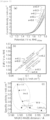
- Figure 5(a) shows results of the linear sweep voltammetry measurement (LSV curves)
- Figure 5(b) shows Tafel plots
- Figure 5(c) is a graph showing correlation between Mn(A')-Mn(B) bond distance and current density.
- a nickel expanded mesh (10 cm ⁇ 10 cm, LW ⁇ 3.7 SW ⁇ 0.9 ST ⁇ 0.8 T) on which a chemical etching treatment was performed by immersing the nickel expanded mesh for 6 minutes in 17.5% hydrochloric acid heated to near the boiling point was prepared as an anode substrate.
- This expanded mesh was subjected to a blast treatment (0.3 MPa) with alumina particles of 60 mesh, and was then immersed for 6 minutes in 20% hydrochloric acid heated to near the boiling point to perform a chemical etching treatment.
- An aqueous solution containing components to be a precursor of a lithium-containing nickel oxide was coated, with a brush, on the surface of the anode substrate after the chemical etching treatment, and was then dried at 80°C for 15 minutes.
- the anode substrate was subjected to a thermal treatment at 600°C for 15 minutes in an oxygen atmosphere.
- the treatments from the coating of the aqueous solution to the thermal treatment were repeated 20 times to obtain an intermediate having an intermediate layer (composition: Li 0.5 Ni 1.5 O 2 ) formed on the surface of the anode substrate.
- a small-sized zero-gap type electrolytic cell using a neutral separator was prepared using: the obtained anode; a separator (trade name "Zirfon” manufactured by AGFA-Gevaert NV); and an active cathode having a catalyst layer containing Ru and Pr oxide and formed thereon.
- the area of the electrodes was set to 19 cm 2 .
- An electrolyte (25% KOH aqueous solution) was supplied to the anode chamber and the cathode chamber forming the electrolytic cell to perform electrolysis at a current density of 6 kA/m 2 for 6 hours in each chamber. The overpotential on that occasion was 250 mV.
- the alkaline water electrolysis anode of the present invention is suitable as, for example, an alkaline water electrolysis anode that forms electrolysis equipment or the like in which electric power having a large output fluctuation, such as renewable energy, is used as a power source.
Landscapes
- Chemical & Material Sciences (AREA)
- Materials Engineering (AREA)
- Engineering & Computer Science (AREA)
- Organic Chemistry (AREA)
- Chemical Kinetics & Catalysis (AREA)
- Metallurgy (AREA)
- Electrochemistry (AREA)
- Inorganic Chemistry (AREA)
- Physics & Mathematics (AREA)
- Thermal Sciences (AREA)
- Electrodes For Compound Or Non-Metal Manufacture (AREA)
- Electrolytic Production Of Non-Metals, Compounds, Apparatuses Therefor (AREA)
- Catalysts (AREA)
Abstract
Description
- The present invention relates to an alkaline water electrolysis anode and a method for producing the same.
- Hydrogen is secondary energy which is suitable for storage and transportation and has small environmental load, and therefore a hydrogen energy system using hydrogen as an energy carrier has been attracting attention. Currently, hydrogen is mainly produced by steam reforming of fossil fuel, or the like. However, from the viewpoint of problems of global warming and exhaustion of fossil fuel, hydrogen production by water electrolysis using renewable energy, such as solar power generation and wind power generation, is important in generic technology. Water electrolysis is low cost, suitable for enlargement of scale, and therefore is a predominant technique for hydrogen production.
- Among the elements which are used for water electrolysis, many of anode materials have an oxygen evolution overpotential of exceeding 0.3 V under actual operation conditions. It can be said that there is room for significant improvement in the oxygen evolution overpotential as compared to the fact that hydrogen evolution and chlorine evolution overpotentials utilized in current electrolysis industry are around 0.1 V. Note that when electric power having a large output fluctuation, such as renewable energy, is used as a power source for water electrolysis, an anode capable of stably retaining excellent catalytic activity over a long period of time is in the development stage and has not yet been put into practical use.
- Current practical water electrolysis is largely divided into two. One is alkaline water electrolysis, in which a high-concentration alkali aqueous solution is used for an electrolyte. The other is solid polymer electrolyte water electrolysis, in which a solid polymer electrolyte (SPE) membrane is used for an electrolyte. When large-scale hydrogen production is performed by water electrolysis, it is said that alkaline water electrolysis, in which an inexpensive material, such as an iron group metal including nickel and the like, is used, is more suitable than solid polymer electrolyte water electrolysis, in which an electrode using a large amount of an expensive noble metal is used.
- With respect to the high-concentration alkali aqueous solution, electric conductivity becomes high as the temperature increases, but corrosiveness also becomes high. Therefore, the upper limit of the operation temperature is controlled to about 80 to about 90°C. The electrolytic cell voltage has been improved to 2 V or less at a current density of 0.6 A·cm-2 by the development of constitutional materials and various piping materials for an electrolytic cell, which are high-temperature resistant and resistant to a high-concentration alkali aqueous solution, and the development of a low-resistivity separator and an electrode which has an enlarged surface area and has a catalyst applied thereon.
- A nickel-based material which is stable in a high-concentration alkali aqueous solution is used as an alkaline water electrolysis anode, and it has been known that in the case of alkaline water electrolysis using a stable power source, a nickel-based anode has a life of several decades or longer. However, when renewable energy is used as a power source, severe conditions, such as sudden start/shutdown and abrupt load fluctuation, are frequent, and therefore deterioration in performance of the nickel-based anode has been problematic.
- Both of the reaction of producing a nickel oxide and the reaction of reducing the produced nickel oxide progress on the surface of nickel-based material. Therefore, elimination of an electrode catalyst formed on the surface of nickel-based material is facilitated with the progress of these reactions. When the electric power for electrolysis is not supplied, the electrolysis stops, and the nickel-based anode is retained at a potential lower than the oxygen evolution potential (1.23 V vs. RHE) and higher than the potential of a hydrogen evolution cathode, which is a counter electrode, (0.00 V vs. RHE). In the electrolytic cell, electromotive force due to various chemical species is generated, so that the anode potential is retained low, and the reaction of reducing the nickel oxide is facilitated by the progress of a battery reaction.
- A current generated by the battery reaction leaks through manifold in the case of, for example, an electrolytic stack obtained by combining a plurality of cells, such as an anode chamber and a cathode chamber. Examples of the countermeasure for preventing such leakage of a current include a method of allowing a minute current to flow continuously during shutdown. However, to allow a minute current to flow continuously during shutdown, special power source control is needed, and oxygen and hydrogen are generated at all times, and therefore there is a problem that excessive labor has to be done in terms of operation management. In addition, preventing a battery reaction by removing liquid immediately after shutdown for the purpose of intentionally avoiding a reverse current state is possible, but it cannot be said that such measure is always an adequate approach when operation with electric power having a large output fluctuation, such as renewable energy, is supposed.
- In the past, platinum group metals, platinum group metal oxides, valve metal oxides, iron group oxides, lanthanide group metal oxides, and the like have been utilized as a catalyst for an oxygen evolution anode (anode catalyst) which is used for alkaline water electrolysis. As other anode catalysts, alloy-based anode catalysts using nickel as a base, such as Ni-Co and Ni-Fe; nickel having an enlarged surface area; electrically conductive oxides (ceramic materials) including spinel-based anode catalysts, such as Co3O4 and NiCo2O4, and perovskite-based anode catalysts, such as LaCoO3 and LaNiO3; noble metal oxides; oxides containing a lanthanide group metal and a noble metal; and the like have also been known.
- In recent years, as the oxygen evolution anode which is used for high-concentration alkaline water electrolysis, an alkaline water electrolysis anode obtained by forming a lithium-containing nickel oxide catalyst layer containing lithium and nickel in a predetermined molar ratio on the surface of a nickel substrate (Patent Literature 1) and an alkaline water electrolysis anode obtained by forming a catalyst layer containing a nickel-cobalt-based oxide, and an iridium oxide or a ruthenium oxide on the surface of a nickel substrate (Patent Literature 2) have been proposed. In addition, an oxygen evolution catalyst which is an A-site ordered perovskite oxide catalyst AMn3Mn4O12 (A = La or Ca) has been proposed (Patent Literature 3). Further, CaMn3O6, CaMn4O8, and CaMn7O12 to be used as an oxygen reduction catalyst have been proposed (
Patent Literatures 4 and 5). - In addition, it has been reported that LiNi0.8Al0.2O2 having a layered rock salt type structure exhibits high oxygen evolution activity (Non-Patent Literature 1). It is presumed that Al plays a role of stabilizing the structure during polarization due to a synergistic effect with Ni. The layered rock salt structure has been developed by a thermal treatment in an oxygen gas. Attention is paid on Al3+ doping because of stabilization of Ni3+ in the LiNiO2 layer and suppression of mixing of Ni2+ in the Li+ layer. Further, it has been reported that LiNi1.8Fe0.2O2 having a layered rock salt type structure exhibits high oxygen evolution activity (Non-Patent Literature 2).
-
- Patent Literature 1:
Japanese Patent Laid-Open No. 2015-86420 - Patent Literature 2:
Japanese Patent Laid-Open No. 2017-190476 - Patent Literature 3:
Japanese Patent No. 5869169 - Patent Literature 4:
U.S. Patent No. 4101716 - Patent Literature 5:
Chinese Patent No. 110416559 -
- Non-Patent Literature 1: Gupta, A.; Chemelewski, W. D.; Buddie Mullins, C.; Goodenough, Adv Mater., 2015, 27 (39), 6063-7.
- Non-Patent Literature 2: Zhu, K.; Wu, T.; Zhu, Y.; Li, X.; Li, M.; Lu, R.; Wang, J.; Zhu, X.; Yang, W., ACS Energy Letters 2017, 2 (7), 1654-1660.
- However, there has been a problem that even in the alkaline water electrolysis anodes proposed in
Patent Literatures 1 and 2, when electric power having a large output fluctuation, such as renewable energy, is used as a power source, the performance is likely to be lowered, making it difficult to use the anodes stably over a long period of time. Note thatPatent Literature 3 describes nothing about an effect obtained by controlling the amount of Ni. Further,Patent Literatures 4 and 5 describe nothing about oxygen evolution. In addition, it cannot necessarily be said that even LiNi0.0Al0.2O2 reported in Non-Patent Literature 1 and LiNi0.8Fe0.2O2 reported in Non-Patent Literature 2 are sufficiently highly active, and there has been still room for further improvement. - The present invention has been completed in view of such problems of the conventional techniques, and an object of the present invention is to provide an alkaline water electrolysis anode such that even when electric power having a large output fluctuation, such as renewable energy, is used as a power source, the electrolysis performance is unlikely to be deteriorated and excellent catalytic activity is retained stably over a long period of time. In addition, another object of the present invention is to provide a method for producing the alkaline water electrolysis anode.
- As a result of diligent studies in order to solve the problems, the present inventors have found that by controlling the content of Ni in a metal composite oxide having a quadruple perovskite oxide structure to change the Mn(A')-Mn(B) bond distance, reaction activation is brought about, and have completed the present invention. It has been reported that quadruple perovskite oxide AA'3B4O12 exhibits higher catalytic activity for oxygen evolution than a simple perovskite oxide ABO3 having the same B-site elements. One of the reasons for this is that the quadruple perovskite oxide has a new adsorption site in which one oxygen atom in the structure is deficient and which is advantageous for reaction. It is presumed that an O-O dimer is formed as an intermediate by depriving an electron from a hydroxyl ion adsorbed to this adsorption site, and the stability of the O-O bond in the A'-B site is changed by a decrease in the bond length, caused by partially substituting Mn(B) with Ni, thereby resulting in easy release as oxygen.
- That is, according to the present invention, an alkaline water electrolysis anode described below is provided.
- [1] An alkaline water electrolysis anode provided with: an electrically conductive substrate at least a surface of which contains nickel or a nickel base alloy; and a catalyst layer disposed on the surface of the electrically conductive substrate, the catalyst layer containing a metal composite oxide having a quadruple perovskite oxide structure, wherein the metal composite oxide contains calcium (Ca), manganese (Mn), and nickel (Ni), and has an atom ratio of Ca/Mn/Ni/O of (1.0)/(6.6 to 7.0)/(0.1 to 0.4)/12.0.
- [2] The alkaline water electrolysis anode according to [1], wherein Mn(A')-Mn(B) bond distance is 3.18 to 3.19 Å.
- [3] The alkaline water electrolysis anode according to [1] or [2], further provided with an intermediate layer disposed between the electrically conductive substrate and the catalyst layer, the intermediate layer containing a lithium-containing nickel oxide represented by compositional formula LixNi2-xO2 wherein 0.02≤x≤0.5.
Further, according to the present invention, a method for producing an alkaline water electrolysis anode, described below, is provided. - [4] A method for producing an alkaline water electrolysis anode, including: a step of subjecting a precursor containing a calcium component, a manganese component, and a nickel component to a thermal treatment at 400 to 900°C in an oxygen-containing atmosphere to obtain a metal composite oxide having a quadruple perovskite oxide structure; and a step of forming a catalyst layer containing the metal composite oxide on a surface of an electrically conductive substrate at least the surface of which contains nickel or a nickel base alloy, wherein
the metal composite oxide contains calcium (Ca), manganese (Mn), and nickel (Ni), and has an atom ratio of Ca/Mn/Ni/O of (1.0)/(6.6 to 7.0)/(0.1 to 0.4)/12.0. - [5] The method for producing an alkaline water electrolysis anode according to [4], wherein the precursor is subjected to a thermal treatment in an oxygen-containing atmosphere having an oxygen partial pressure of 0.2 atm or higher.
- The present invention can provide an alkaline water electrolysis anode being such that even when electric power having a large output fluctuation, such as renewable energy, is used as a power source, the electrolysis performance is unlikely to be deteriorated, and excellent catalytic activity is retained stably over a long period of time. Further, the present invention can provide a method for producing the alkaline water electrolysis anode.
-
- [
Figure 1] Figure 1 is a section view schematically showing one embodiment of an alkaline water electrolysis anode of the present invention. - [
Figure 2] Figure 2 is a diagram schematically showing a crystal structure (quadruple perovskite oxide structure) of metal composite oxides (catalysts). - [
Figure 3] Figure 3 is a graph showing synchrotron radiation X-ray diffraction patterns for metal complex oxides (catalysts). - [
Figure 4] Figure 4(a) is a graph showing Mn K-edge XANES spectra for metal composite oxides (catalysts) andFigure 4(b) is a graph showing Ni K-edge XANES spectra for metal composite oxides (catalysts). - [
Figure 5] Figure 5(a) shows results of linear sweep voltammetry measurement (LSV curves),Figure 5(b) shows Tafel plots, andFigure 5(c) is a graph showing correlation between Mn(A')-Mn(B) bond distance and current density. -
Figure 1 is a section view schematically showing one embodiment of an alkaline water electrolysis anode of the present invention. As shown inFigure 1 , an alkalinewater electrolysis anode 10 of the present embodiment is provided with an electricallyconductive substrate 2, anintermediate layer 4 formed on the surface of the electricallyconductive substrate 2, and acatalyst layer 6 formed on the surface of theintermediate layer 4. Hereinafter, the details on the alkaline water electrolysis anode of the present invention (hereinafter, also simply referred to as "anode") will be described. - The electrically
conductive substrate 2 is an electric conductor that conducts electricity for electrolysis and is an element having a function as a carrier that carries theintermediate layer 4 and thecatalyst layer 6. At least a surface of the electrically conductive substrate 2 (the surface on which theintermediate layer 4 and thecatalyst layer 6 are formed) is formed with nickel or a nickel base alloy. That is, the whole of the electricallyconductive substrate 2 may be formed with nickel or a nickel base alloy, or only the surface of the electricallyconductive substrate 2 may be formed with nickel or a nickel base alloy. Specifically, the electricallyconductive substrate 2 may be such that a coating of nickel or a nickel base alloy is formed on the surface of a metal material, such as iron, stainless steel, aluminum, or titanium, by plating or the like. - The thickness of the electrically conductive substrate is preferably 0.05 to 5 mm. The shape of the electrically conductive substrate is preferably a shape having an opening for removing bubbles of oxygen, hydrogen, and the like to be produced. For example, an expanded mesh or a porous expanded mesh can be used as the electrically conductive substrate. When the electrically conductive substrate has a shape having an opening, the aperture ratio of the electrically conductive substrate is preferably 10 to 95%.
- The anode of the present invention is preferably provided with an intermediate layer disposed between the electrically conductive substrate and the catalyst layer. As shown in
Figure 1 , theintermediate layer 4 is a layer formed on the surface of the electricallyconductive substrate 2. Theintermediate layer 4 suppresses corrosion or the like of the electricallyconductive substrate 2 and fixes thecatalyst layer 6 stably to the electricallyconductive substrate 2. In addition, theintermediate layer 4 also serves as a role of supplying a current quickly to thecatalyst layer 6. Theintermediate layer 4 is preferably formed with a lithium-containing nickel oxide represented by composition formula LixNi2-xO2 (0.02≤x≤0.5). When x in the compositional formula is less than 0.02, the electric conductivity is somewhat insufficient in some cases. On the other hand, when x exceeds 0.5, the physical strength and the chemical stability are somewhat lowered in some cases. Theintermediate layer 4 formed with a lithium-containing nickel oxide represented by the compositional formula has enough electric conductivity for electrolysis, and exhibits excellent physical strength and chemical stability even after the use for a long period of time. - The thickness of the intermediate layer is preferably 0.01 µm or more and 100 µm or less, more preferably 0.1 µm or more and 10 µm or less. When the thickness of the intermediate layer is less than 0.01 µm, the above-described functions are not exhibited. On the other hand, even if the thickness of the intermediate layer is set in such a way as to exceed 100 µm, the above-described functions are unlikely to be exhibited because the voltage loss due to the resistance in the intermediate layer is large, and it is somewhat disadvantageous in terms of production costs or the like in some cases.
- The
catalyst layer 6 is a layer that is formed on the surface of theintermediate layer 4 and has catalytic ability. By interposing theintermediate layer 4, thecatalyst layer 6 is more firmly fixed on the electricallyconductive substrate 2. - The catalyst layer is a layer containing a metal composite oxide having a quadruple perovskite oxide structure, and is preferably a layer substantially formed with a metal composite oxide having a quadruple perovskite oxide structure. Then, this metal composite oxide contains calcium (Ca), manganese (Mn), and nickel (Ni), and has an atom ratio of Ca/Mn/Ni/O of (1.0)/(6.6 to 7.0)/(0.1 to 0.4)/12.0. When the catalyst layer containing a metal composite oxide having a composition in which the ratio of Ca, Mn, Ni, and O is as described above is provided, thereby the electrolysis performance is unlikely to be deteriorated and excellent catalytic activity can be retained stably over a long period of time even when electric power having a large output fluctuation, such as renewable energy, is used as a power source.
- The thickness of the catalyst layer is preferably 0.01 µm or more and 100 µm or less, more preferably 0.1 µm or more and 10 µm or less. When the thickness of the catalyst layer is less than 0.01 µm, the above-described functions are not exhibited. On the other hand, even if the thickness of the catalyst layer is set in such a way as to exceed 100 µm, the above-described functions are unlikely to be exhibited because the voltage loss due to the resistance in the catalyst layer is large, and it is somewhat disadvantageous in terms of production costs or the like in some cases.
- Next, a method for producing an alkaline water electrolysis anode of the present invention will be described. The method for producing an anode, which will be described below, is a method for suitably producing the above-described alkaline water electrolysis anode. The method for producing an anode of the present invention includes a metal composite oxide preparation step and a catalyst layer formation step. The metal composite oxide preparation step is a step of subjecting a precursor containing a calcium component, a manganese component, and a nickel component to a thermal treatment at 400 to 900°C in an oxygen-containing atmosphere to obtain a metal composite oxide having a quadruple perovskite oxide structure. In addition, the catalyst layer formation step is a step of forming a catalyst layer containing the metal composite oxide on the surface of the electrically conductive substrate.
- Note that, if necessary, an intermediate layer can be disposed between the electrically conductive substrate and the catalyst layer, as described above. A method for producing an anode in which an intermediate layer is disposed further includes, prior to the above-described catalyst layer formation step, a step (coating step) of coating an aqueous solution containing a lithium ion and a nickel ion on the surface of the electrically conductive substrate, and a step (intermediate layer formation step) of subjecting the electrically conductive substrate on which the aqueous solution has been coated to a thermal treatment, thereby forming, on the surface of the electrically conductive substrate, an intermediate layer containing a lithium-containing nickel oxide represented by compositional formula LixNi2-xO2 wherein 0.02≤x≤0.5.
- The electrically conductive substrate is preferably subjected to a chemical etching treatment in advance for the purpose of removing contamination particles of a metal, an organic substance, and the like on the surface before forming the intermediate layer and the catalyst layer. The consumption of the electrically conductive substrate by the chemical etching treatment is preferably set to about 30 g/m2 or more and about 400 g/m2 or less. In addition, the surface of the electrically conductive substrate is preferably subjected to a roughening treatment in advance for the purpose of enhancing the adhesiveness with the intermediate layer and the catalyst layer. Examples of the means for the roughening treatment include a blast treatment in which a powder is sprayed, an etching treatment using an acid that can dissolve the substrate, and plasma spraying.
- In the coating step, an aqueous solution containing a lithium ion and a nickel ion is coated on the surface of the electrically conductive substrate. The intermediate layer is formed by a so-called thermal decomposition method. When the intermediate layer is formed by the thermal decomposition method, an aqueous solution of a precursor of the intermediate layer is first prepared. As the precursor containing a lithium component, a known precursor, such as lithium nitrate, lithium carbonate, lithium chloride, lithium hydroxide, and a lithium carboxylate, can be used. Examples of the lithium carboxylate include lithium formate and lithium acetate. As the precursor containing a nickel component, a known precursor, such as nickel nitrate, nickel carbonate, nickel chloride, and a nickel carboxylate, can be used. Examples of the nickel carboxylate include nickel formate and nickel acetate. It is particularly preferable to use at least one of a lithium carboxylate and a nickel carboxylate in particular as the precursor because thereby a dense intermediate layer can be formed even when calcination is performed at a low temperature, as will be described later.
- In the intermediate layer formation step, the electrically conductive substrate on which the aqueous solution has been coated is subjected to a thermal treatment. Thereby, the intermediate layer containing a lithium-containing nickel oxide represented by compositional formula LixNi2-xO2 (0.02≤x≤0.5) can be formed on the surface of the electrically conductive substrate. The thermal treatment temperature at the time when the intermediate layer is formed by the thermal decomposition method can appropriately be set. When the decomposition temperature of the precursor and the production costs are taken into consideration, the thermal treatment temperature is preferably set to 450 to 600°C, more preferably 450 to 550°C. For example, the decomposition temperature of lithium nitrate is about 430°C, and the decomposition temperature of nickel acetate is about 373°C. When the thermal treatment temperature is set to 450°C or higher, thereby each component can more surely be decomposed. When the thermal treatment temperature is set in such a way as to exceed 600°C, the oxidation of the electrically conductive substrate easily progresses, and the electrode resistance increases to bring about an increase in the voltage loss in some cases. The thermal treatment time may appropriately be set taking the reaction rate, the productivity, the oxidation resistance at the surface of the intermediate layer, and the like into consideration.
- By appropriately setting the number of times of coating of the aqueous solution in the above-described coating step, the thickness of the intermediate layer to be formed can be controlled. Note that the coating and drying of the aqueous solution may be repeated for every layer until the uppermost layer is formed, and thereafter the thermal treatment may be performed on the whole layers, or the coating of the aqueous solution and the thermal treatment (pre-treatment) may be repeated for every layer until the uppermost layer is formed, and thereafter the thermal treatment may be performed on the whole layers. The temperature of the pre-treatment and the temperature of the thermal treatment on the whole layers may be the same or different. In addition, the time for the pre-treatment is preferably made shorter than the time for the thermal treatment on the whole layers.
- In the metal composite oxide preparation step, a metal composite oxide is prepared by subjecting a precursor containing a calcium component, a manganese component, and a nickel component to a thermal treatment at 400 to 900°C in an oxygen-containing atmosphere. As the calcium component, a known compound, such as calcium nitrate, calcium carbonate, calcium chloride, calcium hydroxide, and a calcium carboxylate, can be used. Examples of the calcium carboxylate include calcium formate and calcium acetate. As the nickel component, a known compound, such as nickel nitrate, nickel carbonate, nickel chloride, and a nickel carboxylate, can be used. Examples of the nickel carboxylate include nickel formate and nickel acetate. It is preferable to use at least one of a calcium carboxylate and a nickel carboxylate in particular because thereby a denser catalyst layer can be formed. As the manganese component, a known compound, such as manganese nitrate, manganese carbonate, manganese chloride, and a manganese carboxylate, can be used. Examples of the manganese carboxylate include manganese formate and manganese acetate.
- The metal complex oxide (CaMn7-xNixO12) which is a target substance can be prepared by a citric acid complexation method. For example, predetermined amounts of a calcium component, a manganese component, and a nickel component are dissolved in nitric acid, and then a largely excessive amount of citric acid and a stoichiometric amount of 1,2-ethanediol are added thereto under stirring. The resultant solution is heated to around 300°C and the temperature was kept for a certain time, and thereby a dry powder which is the precursor can be obtained. The obtained precursor (dry powder) is subjected to a thermal treatment in an oxygen-containing atmosphere for 2 to 50 hours at 400 to 900°C, preferably 700 to 900°C, and thereby the metal composite oxide (hereinafter, also referred to as "CMO") which is the target substance can be obtained.
- The oxygen partial pressure in the oxygen-containing atmosphere at the time when the precursor is subjected to the thermal treatment is preferably set to 0.2 atm or higher, more preferably 0.5 atm or higher. In addition, the flow rate of the gas containing oxygen to be supplied is preferably controlled to 5 mL/min or less, more preferably 2.5 mL/min or less, in terms of oxygen. When the flow rate of the gas is excessively large (excessively fast), production of the oxide is excessively accelerated in some cases, and therefore the composition of CMO is likely to deviate from the intended composition in some cases. Whether or not the obtained metal composite oxide (CMO) has a quadruple perovskite oxide structure can be ascertained by crystal structure analysis using XRD.
- In the catalyst layer formation step, the catalyst layer containing a metal composite oxide (CMO), which is a catalyst, is formed on the surface of the electrically conductive substrate. Thereby, the intended alkaline water electrolysis anode can be obtained. To form the catalyst layer on the surface of the electrically conductive substrate, a conventionally known method may appropriately be adopted, and the method is not particularly limited. For example, a catalyst ink is prepared by adding a catalyst (CMO) to a solvent containing a particular resin (Nafion (R)) or the like. Then, the prepared catalyst ink is coated on the surface of the electrically conductive substrate or the surface of the intermediate layer formed on the electrically conductive substrate, and, if necessary, dried by heating or the like, and thereby the catalyst layer can be formed on the surface of the electrically conductive substrate.
- The alkaline water electrolysis anode of the present invention can be used as an oxygen evolution anode at the time when alkaline water is electrolyzed. That is, use of the anode of the present invention can form an electrolytic cell, such as an alkaline water electrolytic cell. The types, constitution, and the like of the cathode and separator to be used together with the above-described anode are not particularly limited, and a cathode and a separator which are used in conventional alkaline water electrolysis can be used.
- As the cathode, a substrate made of a material that is bearable to alkaline water electrolysis and a catalyst having a small cathode overpotential are preferably selected and used. As the cathode substrate, a nickel substrate, or a cathode substrate obtained by forming an active cathode by coating the nickel substrate can be used. Examples of the shape of the cathode substrate include an expanded mesh and a porous expanded mesh in addition to a plate shape.
- The cathode material includes porous nickel having a large surface area, a Ni-Mo-based material, and the like. Besides, the cathode material includes Raney nickel-based materials, such as Ni-Al, Ni-Zn, and Ni-Co-Zn; sulfide-based materials, such as Ni-S; and hydrogen absorbing alloy-based materials, such as Ti2Ni; and the like. The catalyst preferably has characteristics of low hydrogen overpotential, high stability against short-circuit, high poisoning resistance, and the like. As other catalysts, metals, such as platinum, palladium, ruthenium, and iridium, and oxides thereof are preferable.
- As the electrolysis separator, asbestos, non-woven fabric, an ion-exchange membrane, a porous polymer membrane, and a composite membrane of an inorganic substance and an organic polymer, and the like can be used. Specifically, an ion-permeable separator such that organic fiber cloth is incorporated in a mixture of a hydrophilic inorganic material, such as a calcium phosphate compound and calcium fluoride, and an organic binding material, such as polysulfone, polypropylene, and polyvinylidene fluoride, can be used. In addition, an ion-permeable separator such that stretched organic fiber cloth is incorporated in a film-forming mixture of an inorganic hydrophilic substance in the form of particles, such as oxides and hydroxides of antimony and zirconium, and an organic binder, such as a fluorocarbon polymer, polysulfone, polypropylene, polyvinyl chloride, and polyvinyl butyral, can be used.
- By using an alkaline water electrolytic cell using the anode of the present invention as a constitutional element, a high-concentration alkali aqueous solution can be electrolyzed. The alkali aqueous solution that is used as the electrolyte is preferably an aqueous solution of an alkaline metal hydroxide, such as potassium hydroxide (KOH) or sodium hydroxide (NaOH). The concentration of the alkali aqueous solution is preferably 1.5% by mass or more and 40% by mass or less. In addition, the concentration of the alkali aqueous solution is preferably 15% by mass or more and 40% by mass or less because the electric conductivity is large, and the electric power consumption can be suppressed. Further, when the costs, the corrosiveness, the viscosity, the operability, and the like are taken into consideration, the concentration of the alkali aqueous solution is preferably 20% by mass or more and 30% by mass or less.
- Hereinafter, the present invention will specifically be described based on Examples, but the present invention is not limited to these Examples. Note that "parts" and "%" in Examples and Comparative Examples are each on a mass basis unless otherwise noticed.
- Stoichiometric amounts of CaCO3, Mn(NO3)2·6H2O, and Ni(NO3)2·6H2O were dissolved in nitric acid. Citric acid in a five-fold molar excessive amount and 1,2-ethanediol in a stoichiometric amount were added to the solution under stirring, and then the resultant mixture was heated to 300°C to obtain a precursor in the form of a powder. The obtained precursor was calcined in the air at 400°C for 1 hours and at 675°C for 12 hours using a heating furnace. Subsequently, calcination was performed in the air at 900°C for 12 hours to obtain a target substance (CMO) in the form of a powder. A solution obtained by dissolving part of the obtained standard substance in an acid was used as a sample, and the composition was analyzed by inductively coupled plasma (ICP) emission spectroscopy. As an inductively coupled plasma emission spectrometer, "ICPS-8100CL," product name, (manufactured by SHIMADZU CORPORATION) was used. As a result, it was ascertained that the chemical composition of the obtained target substance (CMO) is represented by "CaMn7-xNixO12" (five types of compositions wherein x=0.0, 0.1, 0.2, 0.3, and 0.4).
-
Figure 2 is a diagram schematically showing the crystal structure (quadruple perovskite oxide structure) of the metal composite oxides (catalysts). As shown inFigure 2 , it is understood that when Mn(B) in the Mn(A')-Mn(B) bond in CaMn7O12 quadruple perovskite oxide structure is partially substituted with Ni, Ni is incorporated in the B-site of the host matrix without changing any of the state of Mn and the state of O. -
Figure 3 is a graph showing synchrotron radiation X-ray diffraction patterns for the metal complex oxides (catalysts). As shown inFigure 3 , it is understood that the phase transition of the crystal structure is clearly caused by doping of Ni. Note that the disappearance of some diffraction peaks of Ni-doped CMO suggests that a change in the crystal structure occurred at x=0.2. Rietveld precise analysis showed a distorted perovskite structure of triangular symmetry, R3- space group in the case of x=0.0 and showed cubic symmetry, Im3- space group in the case of x ≥0.2. In the case of x=0.1, both of the R3- phase and the Im3- phase were observed. Note that the metal composite oxide (catalyst) was not prepared in the case of x≥0.5 because impurities were present. -
Figure 4(a) is a graph showing Mn K-edge XANES spectra for the metal composite oxides (catalysts) andFigure 4(b) is a graph showing Ni K-edge XANES spectra for the metal composite oxides (catalysts). As shown inFigures 4(a) and 4(b) , the state of Mn remained constant regardless of the Ni doping level. It is presumed that the valence state of Ni is "+3" in all the samples because the absorption edge position is higher than that of NiO. Note that the O K-edge spectra were not changed. Therefore, neither the state of Mn nor the O2p band center, which are factors involved in oxygen evolution ability, are considered to be changed. - Each suspension was obtained by mixing 10 mg of the catalyst, 2 mg of acetylene black (manufactured by Denka Company Limited), 40 µL of a 5% Nafion (R) solution, and 20 µL of a 0.1 mol/L KOH aqueous solution. Each catalyst ink, which was a uniform suspension, was obtained by adding 1.94 mL of tetrahydrofuran to the obtained suspension, and sonicating the resultant mixture for 30 minutes. On a polished glassy carbon (GC) rotating disk electrode (RDE, manufactured by HOKUTO DENKO CORPORATION, diameter 5 mm, 0.196 cm2), 10 µL of the catalyst ink was dropped and then vacuum-dried at room temperature for 12 hours to obtain each working electrode. Then, electrolysis operation was performed using the following three-electrode cell connected to a potentiogalvanostat (trade name "MPG-205-NUC," manufactured by Bio-Logic Science Instruments SAS). Note that linear sweep voltammetry (LSV) was performed as a pre-treatment, and a current was measured at a potential of 1.2 to 1.8 V and a sweep rate of 5 mV/s while the electrode was rotated at 1,600 rpm. In addition, all the electrochemical experiments were conducted in a nitrogen atmosphere, iR correction (R was approximately 12.) was conducted for all the data after the measurement.
Figure 5(a) shows results of the linear sweep voltammetry measurement (LSV curves),Figure 5(b) shows Tafel plots, andFigure 5(c) is a graph showing correlation between Mn(A')-Mn(B) bond distance and current density. [Three-electrode Cell]: - Working electrode: catalyst-coated GC
- Reference electrode: reversible hydrogen electrode (RHE)
- Counter electrode: Pt wire
- Electrolyte: 0.1 mol/L KOH aqueous solution
- As shown in
Figure 5(a) , it is understood that there is correlation between the catalytic activity and the amount of Ni doped and the best activity is exhibited in the case of x=0.4. Note that the decreasing tendency in OER activity corresponds to the decrease in x. In addition, as shown inFigure 5(b) , all the Tafel slopes were about 94 mVdec-1 regardless of x (Ni). It is suggested that the catalytic activity of Ni-doped CMO is not due to a change in the reaction path but to an increase in the reaction rate which is the rate-determining step. As shown inFigure 5(c) , there was clear correlation between the catalytic activity for oxygen evolution and the Mn(A')-Mn(B) bond distance. - A nickel expanded mesh (10 cm × 10 cm, LW × 3.7 SW × 0.9 ST × 0.8 T) on which a chemical etching treatment was performed by immersing the nickel expanded mesh for 6 minutes in 17.5% hydrochloric acid heated to near the boiling point was prepared as an anode substrate. This expanded mesh was subjected to a blast treatment (0.3 MPa) with alumina particles of 60 mesh, and was then immersed for 6 minutes in 20% hydrochloric acid heated to near the boiling point to perform a chemical etching treatment. An aqueous solution containing components to be a precursor of a lithium-containing nickel oxide was coated, with a brush, on the surface of the anode substrate after the chemical etching treatment, and was then dried at 80°C for 15 minutes. Subsequently, the anode substrate was subjected to a thermal treatment at 600°C for 15 minutes in an oxygen atmosphere. The treatments from the coating of the aqueous solution to the thermal treatment were repeated 20 times to obtain an intermediate having an intermediate layer (composition: Li0.5Ni1.5O2) formed on the surface of the anode substrate.
- Next, an anode having a catalyst layer (composition: CaMn6.6Ni0.4O12) formed on the surface of the intermediate layer was obtained by the same method as in Production Example 1 described above using the catalyst ink of the metal composite oxide (catalyst) (x=0.4) obtained in Production Example 1.
- A small-sized zero-gap type electrolytic cell using a neutral separator was prepared using: the obtained anode; a separator (trade name "Zirfon" manufactured by AGFA-Gevaert NV); and an active cathode having a catalyst layer containing Ru and Pr oxide and formed thereon. The area of the electrodes was set to 19 cm2. An electrolyte (25% KOH aqueous solution) was supplied to the anode chamber and the cathode chamber forming the electrolytic cell to perform electrolysis at a current density of 6 kA/m2 for 6 hours in each chamber. The overpotential on that occasion was 250 mV. Subsequently, the anode and the cathode were brought into a short-circuit state (0 kA/m2) to shut down the electrolysis for 15 hours. Shutdown tests in which the operation from the electrolysis to the shutdown was defined as 1 cycle were conducted. As a result, it was ascertained that the voltage was kept stable in the shutdown tests of 16 times.
- The alkaline water electrolysis anode of the present invention is suitable as, for example, an alkaline water electrolysis anode that forms electrolysis equipment or the like in which electric power having a large output fluctuation, such as renewable energy, is used as a power source.
-
- 2
- Electrically conductive substrate
- 4
- Intermediate layer
- 6
- Catalyst layer
- 10
- Alkaline water electrolysis anode
Claims (5)
- An alkaline water electrolysis anode comprising:an electrically conductive substrate at least a surface of which comprises nickel or a nickel base alloy; anda catalyst layer disposed on the surface of the electrically conductive substrate, the catalyst layer comprising a metal composite oxide having a quadruple perovskite oxide structure, whereinthe metal composite oxide comprises calcium (Ca), manganese (Mn), and nickel (Ni), and has an atom ratio of Ca/Mn/Ni/O of (1.0)/(6.6 to 7.0)/(0.1 to 0.4)/12.0.
- The alkaline water electrolysis anode according to claim 1, wherein Mn(A')-Mn(B) bond distance is 3.18 to 3.19 Å.
- The alkaline water electrolysis anode according to claim 1 or 2, further comprising an intermediate layer disposed between the electrically conductive substrate and the catalyst layer, the intermediate layer comprising a lithium-containing nickel oxide represented by compositional formula LixNi2-xO2 wherein 0.02≤x≤0.5.
- A method for producing an alkaline water electrolysis anode, comprising:a step of subjecting a precursor comprising a calcium component, a manganese component, and a nickel component to a thermal treatment at 400 to 900°C in an oxygen-containing atmosphere to obtain a metal composite oxide having a quadruple perovskite oxide structure; anda step of forming a catalyst layer comprising the metal composite oxide on a surface of an electrically conductive substrate at least the surface of which comprises nickel or a nickel base alloy, whereinthe metal composite oxide comprises calcium (Ca), manganese (Mn), and nickel (Ni), and has an atom ratio of Ca/Mn/Ni/O of (1.0)/(6.6 to 7.0)/(0.1 to 0.4)/12.0.
- The method for producing an alkaline water electrolysis anode according to claim 4, wherein the precursor is subjected to a thermal treatment in an oxygen-containing atmosphere having an oxygen partial pressure of 0.2 atm or higher.
Applications Claiming Priority (2)
| Application Number | Priority Date | Filing Date | Title |
|---|---|---|---|
| JP2020174096A JP7694893B2 (en) | 2020-10-15 | 2020-10-15 | Anode for alkaline water electrolysis and method for producing same |
| PCT/JP2021/038117 WO2022080466A1 (en) | 2020-10-15 | 2021-10-14 | Anode for alkaline water electrolysis and method for producing same |
Publications (4)
| Publication Number | Publication Date |
|---|---|
| EP4230773A1 true EP4230773A1 (en) | 2023-08-23 |
| EP4230773A4 EP4230773A4 (en) | 2024-07-10 |
| EP4230773B1 EP4230773B1 (en) | 2026-04-01 |
| EP4230773C0 EP4230773C0 (en) | 2026-04-01 |
Family
ID=81208172
Family Applications (1)
| Application Number | Title | Priority Date | Filing Date |
|---|---|---|---|
| EP21880201.5A Active EP4230773B1 (en) | 2020-10-15 | 2021-10-14 | Anode for alkaline water electrolysis and method for producing same |
Country Status (8)
| Country | Link |
|---|---|
| US (1) | US20230332309A1 (en) |
| EP (1) | EP4230773B1 (en) |
| JP (1) | JP7694893B2 (en) |
| KR (1) | KR102559826B1 (en) |
| CN (1) | CN116507413B (en) |
| CA (1) | CA3194841C (en) |
| ES (1) | ES3068217T3 (en) |
| WO (1) | WO2022080466A1 (en) |
Families Citing this family (3)
| Publication number | Priority date | Publication date | Assignee | Title |
|---|---|---|---|---|
| JP2024054920A (en) * | 2022-10-06 | 2024-04-18 | 株式会社タクマ | Equipment for converting carbon dioxide into solid form and method for converting carbon dioxide into solid form |
| US20260237835A1 (en) | 2022-12-21 | 2026-08-13 | Lg Energy Solution, Ltd. | Battery pack and vehicle including same |
| KR20260059363A (en) | 2024-10-23 | 2026-04-30 | 한국과학기술원 | Anode oxide and method for producing the same |
Family Cites Families (15)
| Publication number | Priority date | Publication date | Assignee | Title |
|---|---|---|---|---|
| US4101716A (en) | 1977-08-15 | 1978-07-18 | Exxon Research & Engineering Co. | Use of high surface area mixed metal oxides of manganese and calcium in electrochemical processes |
| JP2004281105A (en) | 2003-03-13 | 2004-10-07 | Ngk Insulators Ltd | Chromium poisoning control materials and electrochemical devices |
| US20070072046A1 (en) * | 2005-09-26 | 2007-03-29 | General Electric Company | Electrochemcial cell structures and methods of making the same |
| JP2015086420A (en) | 2013-10-29 | 2015-05-07 | 国立大学法人横浜国立大学 | Anode for alkali water electrolysis |
| JP5869169B1 (en) * | 2015-06-01 | 2016-02-24 | 公立大学法人大阪府立大学 | Perovskite oxide catalyst for oxygen evolution reaction |
| JP6615682B2 (en) | 2016-04-12 | 2019-12-04 | デノラ・ペルメレック株式会社 | Anode for alkaline water electrolysis and method for producing anode for alkaline water electrolysis |
| JP6978759B2 (en) * | 2016-11-16 | 2021-12-08 | 国立研究開発法人産業技術総合研究所 | Gas diffusion layer for air electrode |
| JP6764994B2 (en) * | 2017-02-21 | 2020-10-07 | 旭化成株式会社 | Anode, anode for water electrolysis, electrolysis cell, and method for producing hydrogen |
| DE102017205339A1 (en) * | 2017-03-29 | 2018-10-04 | Forschungszentrum Jülich GmbH | Chemically stable, oxidic electrocatalyst for the evolution of oxygen during the alkaline water electrolysis based on BaCoO3-delta, process for its preparation and comprehensive anode and catalytically active and chemically stable reaction product thereof |
| JP2018178221A (en) * | 2017-04-18 | 2018-11-15 | 株式会社豊田自動織機 | Method for producing fatty acid salt |
| JP2019137596A (en) * | 2018-02-14 | 2019-08-22 | 学校法人神奈川大学 | Composite material and method for producing the same, catalyst and metal air battery |
| DK3763849T3 (en) * | 2018-03-07 | 2022-12-12 | De Nora Permelec Ltd | Electrolysis electrode and method of manufacturing the same |
| CN110416559B (en) | 2018-04-26 | 2022-01-28 | 天津大学 | Load type calcium manganese oxide composite material and preparation method and application thereof |
| CN110860292A (en) * | 2019-10-08 | 2020-03-06 | 南京航空航天大学 | A kind of cation co-doped perovskite catalyst for oxygen evolution reaction and preparation method thereof |
| JP6975297B1 (en) * | 2020-08-28 | 2021-12-01 | デノラ・ペルメレック株式会社 | Anode for alkaline water electrolysis |
-
2020
- 2020-10-15 JP JP2020174096A patent/JP7694893B2/en active Active
-
2021
- 2021-10-14 EP EP21880201.5A patent/EP4230773B1/en active Active
- 2021-10-14 KR KR1020237014454A patent/KR102559826B1/en active Active
- 2021-10-14 US US18/248,840 patent/US20230332309A1/en not_active Abandoned
- 2021-10-14 WO PCT/JP2021/038117 patent/WO2022080466A1/en not_active Ceased
- 2021-10-14 CA CA3194841A patent/CA3194841C/en active Active
- 2021-10-14 CN CN202180070108.6A patent/CN116507413B/en active Active
- 2021-10-14 ES ES21880201T patent/ES3068217T3/en active Active
Also Published As
| Publication number | Publication date |
|---|---|
| KR20230062677A (en) | 2023-05-09 |
| EP4230773A4 (en) | 2024-07-10 |
| CA3194841A1 (en) | 2022-04-21 |
| CN116507413B (en) | 2024-03-22 |
| KR102559826B1 (en) | 2023-07-25 |
| US20230332309A1 (en) | 2023-10-19 |
| CA3194841C (en) | 2023-08-29 |
| EP4230773B1 (en) | 2026-04-01 |
| CN116507413A (en) | 2023-07-28 |
| JP7694893B2 (en) | 2025-06-18 |
| WO2022080466A1 (en) | 2022-04-21 |
| EP4230773C0 (en) | 2026-04-01 |
| ES3068217T3 (en) | 2026-05-28 |
| JP2022065484A (en) | 2022-04-27 |
Similar Documents
| Publication | Publication Date | Title |
|---|---|---|
| EP4230772B1 (en) | Anode for alkaline water electrolysis and method for producing same | |
| CA3093203C (en) | Electrolysis electrode and method for manufacturing same | |
| CA3133201C (en) | Alkaline water electrolysis method and alkaline water electrolysis anode | |
| EP4230773B1 (en) | Anode for alkaline water electrolysis and method for producing same | |
| JP2003508877A (en) | Anode structure of fuel cell for obtaining resistance to voltage reversal | |
| EP4190944B1 (en) | Anode for alkaline water electrolysis and method for producing same | |
| EP4190443A1 (en) | Dry reforming catalyst comprising perovskite structure material having eluted transition element, method for manufacturing same, dry reforming catalyst system comprising same, and solid oxide fuel cell comprising same | |
| CA3186983C (en) | Anode for alkaline water electrolysis and method for producing same | |
| KR20210033744A (en) | Cathode composition for carbon dioxide decomposition, solid oxide electrolysis cell for carbon dioxide decomposition and manufacturing method for the cathode composition | |
| KR102389165B1 (en) | Cathode composition containing fluorine for carbon dioxide decomposition, solid oxide electrolysis cell for carbon dioxide decomposition and manufacturing method for the cathode composition |
Legal Events
| Date | Code | Title | Description |
|---|---|---|---|
| STAA | Information on the status of an ep patent application or granted ep patent |
Free format text: STATUS: THE INTERNATIONAL PUBLICATION HAS BEEN MADE |
|
| PUAI | Public reference made under article 153(3) epc to a published international application that has entered the european phase |
Free format text: ORIGINAL CODE: 0009012 |
|
| STAA | Information on the status of an ep patent application or granted ep patent |
Free format text: STATUS: REQUEST FOR EXAMINATION WAS MADE |
|
| 17P | Request for examination filed |
Effective date: 20230328 |
|
| AK | Designated contracting states |
Kind code of ref document: A1 Designated state(s): AL AT BE BG CH CY CZ DE DK EE ES FI FR GB GR HR HU IE IS IT LI LT LU LV MC MK MT NL NO PL PT RO RS SE SI SK SM TR |
|
| DAV | Request for validation of the european patent (deleted) | ||
| DAX | Request for extension of the european patent (deleted) | ||
| A4 | Supplementary search report drawn up and despatched |
Effective date: 20240611 |
|
| RIC1 | Information provided on ipc code assigned before grant |
Ipc: B01J 37/14 20060101ALI20240605BHEP Ipc: B01J 37/08 20060101ALI20240605BHEP Ipc: B01J 37/02 20060101ALI20240605BHEP Ipc: B01J 23/889 20060101ALI20240605BHEP Ipc: C25B 11/073 20210101AFI20240605BHEP |
|
| STAA | Information on the status of an ep patent application or granted ep patent |
Free format text: STATUS: EXAMINATION IS IN PROGRESS |
|
| 17Q | First examination report despatched |
Effective date: 20250409 |
|
| GRAP | Despatch of communication of intention to grant a patent |
Free format text: ORIGINAL CODE: EPIDOSNIGR1 |
|
| STAA | Information on the status of an ep patent application or granted ep patent |
Free format text: STATUS: GRANT OF PATENT IS INTENDED |
|
| INTG | Intention to grant announced |
Effective date: 20251022 |
|
| RIN1 | Information on inventor provided before grant (corrected) |
Inventor name: UCHIMOTO, YOSHIHARU Inventor name: UCHIYAMA, TOMOKI Inventor name: MITSUSHIMA, SHIGENORI Inventor name: KURODA, YOSHIYUKI Inventor name: NAGASAWA, KENSAKU Inventor name: NISHIKI, YOSHINORI |
|
| GRAS | Grant fee paid |
Free format text: ORIGINAL CODE: EPIDOSNIGR3 |
|
| GRAA | (expected) grant |
Free format text: ORIGINAL CODE: 0009210 |
|
| STAA | Information on the status of an ep patent application or granted ep patent |
Free format text: STATUS: THE PATENT HAS BEEN GRANTED |
|
| AK | Designated contracting states |
Kind code of ref document: B1 Designated state(s): AL AT BE BG CH CY CZ DE DK EE ES FI FR GB GR HR HU IE IS IT LI LT LU LV MC MK MT NL NO PL PT RO RS SE SI SK SM TR |
|
| REG | Reference to a national code |
Ref country code: CH Ref legal event code: F10 Free format text: ST27 STATUS EVENT CODE: U-0-0-F10-F00 (AS PROVIDED BY THE NATIONAL OFFICE) Effective date: 20260401 Ref country code: GB Ref legal event code: FG4D |
|
| REG | Reference to a national code |
Ref country code: DE Ref legal event code: R096 Ref document number: 602021051360 Country of ref document: DE |
|
| REG | Reference to a national code |
Ref country code: IE Ref legal event code: FG4D |
|
| U01 | Request for unitary effect filed |
Effective date: 20260420 |
|
| U07 | Unitary effect registered |
Designated state(s): AT BE BG DE DK EE FI FR IT LT LU LV MT NL PT RO SE SI Effective date: 20260424 |
|
| REG | Reference to a national code |
Ref country code: ES Ref legal event code: FG2A Ref document number: 3068217 Country of ref document: ES Kind code of ref document: T3 Effective date: 20260528 |