EP4230514A1 - Gas inspecting method, and gas inspecting facility - Google Patents
Gas inspecting method, and gas inspecting facility Download PDFInfo
- Publication number
- EP4230514A1 EP4230514A1 EP21880114.0A EP21880114A EP4230514A1 EP 4230514 A1 EP4230514 A1 EP 4230514A1 EP 21880114 A EP21880114 A EP 21880114A EP 4230514 A1 EP4230514 A1 EP 4230514A1
- Authority
- EP
- European Patent Office
- Prior art keywords
- gas
- inspection
- line
- facility
- combustible
- Prior art date
- Legal status (The legal status is an assumption and is not a legal conclusion. Google has not performed a legal analysis and makes no representation as to the accuracy of the status listed.)
- Pending
Links
Images


Classifications
-
- G—PHYSICS
- G01—MEASURING; TESTING
- G01N—INVESTIGATING OR ANALYSING MATERIALS BY DETERMINING THEIR CHEMICAL OR PHYSICAL PROPERTIES
- G01N1/00—Sampling; Preparing specimens for investigation
- G01N1/02—Devices for withdrawing samples
- G01N1/22—Devices for withdrawing samples in the gaseous state
- G01N1/2247—Sampling from a flowing stream of gas
-
- B—PERFORMING OPERATIONS; TRANSPORTING
- B63—SHIPS OR OTHER WATERBORNE VESSELS; RELATED EQUIPMENT
- B63B—SHIPS OR OTHER WATERBORNE VESSELS; EQUIPMENT FOR SHIPPING
- B63B25/00—Load-accommodating arrangements, e.g. stowing, trimming; Vessels characterised thereby
- B63B25/02—Load-accommodating arrangements, e.g. stowing, trimming; Vessels characterised thereby for bulk goods
- B63B25/08—Load-accommodating arrangements, e.g. stowing, trimming; Vessels characterised thereby for bulk goods fluid
- B63B25/12—Load-accommodating arrangements, e.g. stowing, trimming; Vessels characterised thereby for bulk goods fluid closed
- B63B25/16—Load-accommodating arrangements, e.g. stowing, trimming; Vessels characterised thereby for bulk goods fluid closed heat-insulated
-
- B—PERFORMING OPERATIONS; TRANSPORTING
- B63—SHIPS OR OTHER WATERBORNE VESSELS; RELATED EQUIPMENT
- B63B—SHIPS OR OTHER WATERBORNE VESSELS; EQUIPMENT FOR SHIPPING
- B63B79/00—Monitoring properties or operating parameters of vessels in operation
- B63B79/30—Monitoring properties or operating parameters of vessels in operation for diagnosing, testing or predicting the integrity or performance of vessels
-
- F—MECHANICAL ENGINEERING; LIGHTING; HEATING; WEAPONS; BLASTING
- F17—STORING OR DISTRIBUTING GASES OR LIQUIDS
- F17C—VESSELS FOR CONTAINING OR STORING COMPRESSED, LIQUEFIED OR SOLIDIFIED GASES; FIXED-CAPACITY GAS-HOLDERS; FILLING VESSELS WITH, OR DISCHARGING FROM VESSELS, COMPRESSED, LIQUEFIED, OR SOLIDIFIED GASES
- F17C13/00—Details of vessels or of the filling or discharging of vessels
- F17C13/02—Special adaptations of indicating, measuring, or monitoring equipment
-
- G—PHYSICS
- G01—MEASURING; TESTING
- G01N—INVESTIGATING OR ANALYSING MATERIALS BY DETERMINING THEIR CHEMICAL OR PHYSICAL PROPERTIES
- G01N1/00—Sampling; Preparing specimens for investigation
- G01N1/02—Devices for withdrawing samples
- G01N1/22—Devices for withdrawing samples in the gaseous state
- G01N1/2226—Sampling from a closed space, e.g. food package, head space
-
- G—PHYSICS
- G01—MEASURING; TESTING
- G01N—INVESTIGATING OR ANALYSING MATERIALS BY DETERMINING THEIR CHEMICAL OR PHYSICAL PROPERTIES
- G01N33/00—Investigating or analysing materials by specific methods not covered by groups G01N1/00 - G01N31/00
- G01N33/0004—Gaseous mixtures, e.g. polluted air
- G01N33/0009—General constructional details of gas analysers, e.g. portable test equipment
-
- G—PHYSICS
- G01—MEASURING; TESTING
- G01N—INVESTIGATING OR ANALYSING MATERIALS BY DETERMINING THEIR CHEMICAL OR PHYSICAL PROPERTIES
- G01N33/00—Investigating or analysing materials by specific methods not covered by groups G01N1/00 - G01N31/00
- G01N33/22—Fuels; Explosives
- G01N33/225—Gaseous fuels, e.g. natural gas
-
- F—MECHANICAL ENGINEERING; LIGHTING; HEATING; WEAPONS; BLASTING
- F17—STORING OR DISTRIBUTING GASES OR LIQUIDS
- F17C—VESSELS FOR CONTAINING OR STORING COMPRESSED, LIQUEFIED OR SOLIDIFIED GASES; FIXED-CAPACITY GAS-HOLDERS; FILLING VESSELS WITH, OR DISCHARGING FROM VESSELS, COMPRESSED, LIQUEFIED, OR SOLIDIFIED GASES
- F17C2250/00—Accessories; Control means; Indicating, measuring or monitoring of parameters
- F17C2250/04—Indicating or measuring of parameters as input values
- F17C2250/0404—Parameters indicated or measured
- F17C2250/0447—Composition; Humidity
- F17C2250/0452—Concentration of a product
-
- F—MECHANICAL ENGINEERING; LIGHTING; HEATING; WEAPONS; BLASTING
- F17—STORING OR DISTRIBUTING GASES OR LIQUIDS
- F17C—VESSELS FOR CONTAINING OR STORING COMPRESSED, LIQUEFIED OR SOLIDIFIED GASES; FIXED-CAPACITY GAS-HOLDERS; FILLING VESSELS WITH, OR DISCHARGING FROM VESSELS, COMPRESSED, LIQUEFIED, OR SOLIDIFIED GASES
- F17C2270/00—Applications
- F17C2270/01—Applications for fluid transport or storage
- F17C2270/0102—Applications for fluid transport or storage on or in the water
- F17C2270/0105—Ships
-
- G—PHYSICS
- G01—MEASURING; TESTING
- G01N—INVESTIGATING OR ANALYSING MATERIALS BY DETERMINING THEIR CHEMICAL OR PHYSICAL PROPERTIES
- G01N1/00—Sampling; Preparing specimens for investigation
- G01N1/02—Devices for withdrawing samples
- G01N1/22—Devices for withdrawing samples in the gaseous state
- G01N1/2226—Sampling from a closed space, e.g. food package, head space
- G01N2001/2238—Sampling from a closed space, e.g. food package, head space the gas being compressed or pressurized
Definitions
- the present application relates to a gas inspection method performed in a liquefied gas carrier and a gas inspection facility located in the liquefied gas carrier.
- a liquefied gas carrier is a ship that carries a liquefied gas, prepared by liquefying a combustible gas, from one land terminal to another land terminal (see PTL 1).
- the liquefied gas carrier includes facilities (hereinafter referred to as "combustible gas facilities”) such as a tank and a pipe, which contain a combustible gas.
- the combustible gas facility includes an extractor that extracts s gas therein. The gas extracted through the extractor is subjected to inspection (hereinafter referred to as "gas inspection") regarding properties, combustible gas concentration, and the like by a gas inspector.
- the liquefied gas carrier includes a large number of extractors located at the combustible gas facilities, it is not realistic to provide the gas inspectors at all the extractors. Therefore, it is effective to perform the gas inspection by attaching a detachable gas inspector to each extractor according to need.
- a problem is how to perform disposal treatment of the gas (hereinafter referred to as an "inspection target gas") extracted for the gas inspection.
- the present application was prepared under these circumstances, and an object of the present application is to provide a gas inspection method and a gas inspection facility, each of which, when performing gas inspection by using a detachable gas inspector in a liquefied gas carrier, can appropriately perform disposal treatment of an inspection target gas extracted for the gas inspection.
- a gas inspection method is a gas inspection method performed in a liquefied gas carrier.
- the gas inspection method includes:
- a gas inspection facility is a gas inspection facility located at a liquefied gas carrier.
- the gas inspection facility includes: an extractor located at a combustible gas facility; a disposal line connected to an exhaust gas treatment facility; and a gas inspection structure that is detachably attached to between the extractor and the disposal line and performs gas inspection of an inspection target gas extracted from the combustible gas facility.
- the above configurations can provide a gas inspection method and a gas inspection facility, each of which, when performing gas inspection by using a detachable gas inspector in a liquefied gas carrier, can appropriately perform disposal treatment of an inspection target gas extracted for the gas inspection.
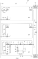
- FIG. 1 is a schematic diagram of the gas inspection facility 100.
- the gas inspection facility 100 is located in a liquefied gas carrier 101 that carries a liquefied gas, prepared by liquefying a combustible gas, from one land terminal to another land terminal.
- a liquefied gas carrier 101 that carries a liquefied gas, prepared by liquefying a combustible gas, from one land terminal to another land terminal.
- the combustible gas include a hydrogen gas and a natural gas.
- the gas inspection facility 100 includes extractors 10, a disposal line 20, a gas inspection structure 30, and an inert gas supply structure 50. Hereinafter, these components will be described in order.
- the extractor 10 is a device that extracts a gas from a combustible gas facility 102.
- the combustible gas facility 102 is a facility that contains the combustible gas therein. For example, since a tank that stores the liquefied gas contains the combustible gas therein, such tank corresponds to the combustible gas facility 102. Moreover, when the combustible gas temporarily flows in a pipe through which the liquefied gas flows, not only a pipe through which the combustible gas flows but also the pipe through which the liquefied gas flows corresponds to the combustible gas facility 102.
- FIG. 1 shows three combustible gas facilities 102, and the extractors 10 are located for the respective combustible gas facilities 102.
- Each extractor 10 of the embodiment includes an extraction line 11 and an extraction valve 12 located on the extraction line 11.
- one extraction valve 12 is located on each extraction line 11.
- two or more extraction valves 12 may be located on each extraction line 11.
- An opening degree of the extraction valve 12 may be manually adjusted, may be automatically adjusted, or may be able to be both manually and automatically adjusted. The same is true for below-described valves.
- the disposal line 20 is a line connected to an exhaust gas treatment facility.
- the exhaust gas treatment facility includes: a ship exhaust gas treatment facility 110 located at the liquefied gas carrier 101; and a land exhaust gas treatment facility 111 located on land.
- the ship exhaust gas treatment facility 110 includes: a liquefied gas combustor that treats the liquefied gas; a vent mast that prevents an increase in pressure in a tank that stores the liquefied gas; and the like.
- the disposal line 20 of the embodiment is connected to both the ship exhaust gas treatment facility 110 and the land exhaust gas treatment facility 111. When the liquefied gas carrier 101 lies alongside the land terminal, the land exhaust gas treatment facility 111 can be connected to the disposal line 20 through a line extending from the land exhaust gas treatment facility 111.
- the disposal line 20 includes connection lines 21, a ship branch line 22, and a land branch line 23.
- the connection lines 21 are located so as to correspond to respective work areas 104 at each of which the extractor 10 is located. Each work area 104 may be indoor or outdoor.
- Connection valves 24 are located on the respective connection lines 21.
- connection lines 21 are combined with each other, and the combined line is divided into the ship branch line 22 and the land branch line 23.
- the ship branch line 22 is a line connecting the connection lines 21 and the ship exhaust gas treatment facility 110.
- the land branch line 23 is a line connecting the connection lines 21 and the land exhaust gas treatment facility 111.
- the connection lines 21 may not be combined with each other, and each connection line 21 may be divided into the ship branch line 22 and the land branch line 23.
- a ship valve 25 is located on the ship branch line 22, and a land valve 26 is located on the land branch line 23.
- the gas inspection structure 30 is a unit that performs gas inspection of a gas (inspection target gas) extracted from the combustible gas facility 102 through the extractor 10.
- the gas inspection structure 30 can be carried and can be detachably connected to each extractor 10.
- the gas inspection structure 30 is connected to the extractor 10 through the inert gas supply structure 50 and a flexible pipe 61.
- the gas inspection structure 30 is connected to the connection line 21 of the disposal line 20 through a flexible pipe 62.
- the gas inspection structure 30 is detachably attached to between the extractor 10 and the disposal line 20.
- the gas inspection structure 30 includes a direct connection line 31, an inlet line 32, an outlet line 33, a main line 34, and a bypass line 35.
- the direct connection line 31 is a line connecting an inlet and outlet of the gas inspection structure 30.
- the inlet line 32 is a line which extends from a portion, close to the inlet, of the direct connection line 31 and into which the inspection target gas flows.
- the outlet line 33 is a line which is coupled to a portion, close to the outlet, of the direct connection line 31 and from which the inspection target gas flows out.
- the main line 34 is a line which connects the inlet line 32 and the outlet line 33 and on which a below-described gas inspector 37 is located.
- the bypass line 35 is a line which connects the inlet line 32 and the outlet line 33 and is located in parallel with the main line 34.
- the gas inspection structure 30 further includes the gas inspector 37, a direct connection valve 38, a flow rate adjustment valve 39, a switching valve 40, a check valve 41, and a flow meter 42.
- the gas inspector 37 is a device that is located on the main line 34 and inspects the inspection target gas extracted from the combustible gas facility 102.
- the gas inspector 37 of the embodiment is a concentration inspector that inspects a percentage of the combustible gas in the inspection target gas.
- the gas inspector 37 may be a device other than the concentration inspector.
- the gas inspector 37 may be detachably located on the main line 34.
- the direct connection valve 38 is located on the direct connection line 31 and between the portion of the direct connection line 31 from which the inlet line 32 extends and the portion of the direct connection line 31 to which the outlet line 33 is coupled.
- the flow rate adjustment valve 39 is located on the inlet line 32.
- the flow rate adjustment valve 39 can adjust the flow rate of the inspection target gas in the inlet line 32, and therefore, can adjust the flow rate of the inspection target gas flowing into the gas inspector 37.
- the switching valve 40 is located at a border portion of the inlet line 32, the main line 34, and the bypass line 35.
- the switching valve 40 is a so-called three-way valve and can select any of the main line 34 and the bypass line 35 as a line to which the inspection target gas having flowed through the inlet line 32 is supplied.
- the check valve 41 is located on the main line 34 and downstream of the gas inspector 37.
- the check valve 41 is a valve that prevents the inspection target gas from flowing backward to the gas inspector 37.
- the flow meter 42 is located on the inlet line 32 and can measure the flow rate of the inspection target gas flowing through the inlet line 32.
- the flow meter 42 of the embodiment is located downstream of the flow rate adjustment valve 39. However, the flow meter 42 may be located upstream of the flow rate adjustment valve 39.
- the inert gas supply structure 50 is a unit that supplies an inert gas to between the extractor 10 and the gas inspection structure 30.
- the inert gas include a nitrogen gas and an argon gas.
- the inert gas supply structure 50 can be carried and can be detachably attached to between the extractor 10 and the gas inspection structure 30.
- the inert gas supply structure 50 is connected to the gas inspection structure 30 through the flexible pipe 61.
- the inert gas supply structure 50 includes: a direct connection line 51 connecting an inlet and outlet of the inert gas supply structure 50; a supply line 52 coupled to the direct connection line 51; and a supply valve 53 located on the supply line 52. Moreover, the supply line 52 can be detachably connected to an inert gas supplier 105 through a flexible pipe 63.
- the inert gas supplier 105 is located in each work area 104.
- the inert gas supplier 105 is connected to an inert gas line 106 laid in the liquefied gas carrier 101.
- the inert gas supplier 105 can extract the inert gas in the inert gas line 106.
- the inert gas supplier 105 includes an inert gas supply line 107 and an inert gas supply valve 108 located on the inert gas supply line 107.
- the inert gas is supplied to a gas inspection line 70 by using the inert gas supply structure 50.
- the inert gas may be supplied to the gas inspection line 70 by another method.
- the inert gas may be supplied to the gas inspection line 70 by supplying the inert gas from the inert gas supplier 105 to the combustible gas facility 102.
- FIG. 2 is a flowchart showing the gas inspection method.
- the gas inspection method described below may be manually performed or may be automatically performed.
- the gas inspection structure 30 and the inert gas supply structure 50 are attached to between the extractor 10 and the disposal line 20 (Step S1). Specifically, the gas inspection structure 30 is attached to the extractor 10 through the inert gas supply structure 50 and the flexible pipe 61. Then, the gas inspection structure 30 is attached to the disposal line 20 through the flexible pipe 62. At this time, the inert gas supply structure 50 is attached to the inert gas supplier 105 through the flexible pipe 63.
- the extractor 10, the inert gas supply structure 50, the flexible pipe 61, the gas inspection structure 30, the flexible pipe 62, and the disposal line 20 are connected to each other in this order from an upstream side and form the gas inspection line 70.
- the gas inspection line 70 is formed between the combustible gas facility 102 and the ship exhaust gas treatment facility 110 and between the combustible gas facility 102 and the land exhaust gas treatment facility 111.
- all the valves 12, 24, 25, 26, 38, 39, and 53 other than the switching valve 40 are closed.
- the inspection target gas is introduced from the combustible gas facility 102 to the gas inspection line 70 (Step S2). Specifically, the extraction valve 12, the direct connection valve 38, the connection valve 24, and the ship valve 25 are open. With this, the inspection target gas extracted from the combustible gas facility 102 flows through the gas inspection line 70 toward the ship exhaust gas treatment facility 110. To be specific, the inspection target gas having flowed through the gas inspection line 70 is discharged to the ship exhaust gas treatment facility 110, not the work area 104.
- Step S3 the flow rate of the inspection target gas is adjusted (Step S3). Specifically, the direct connection valve 38 is closed, and the flow rate adjustment valve 39 is open. Then, the switching valve 40 is operated such that the inspection target gas having flowed through the inlet line 32 flows through the bypass line 35. With this, the inspection target gas having flowed into the gas inspection structure 30 flows through the bypass line 35 and flows out from the gas inspection structure 30. In this state, while confirming the flow meter 42, the flow rate adjustment valve 39 is adjusted such that the flow rate of the inspection target gas becomes a preset flow rate.
- the gas inspection of the inspection target gas is performed by using the gas inspector 37 of the gas inspection structure 30 (Step S4).
- the switching valve 40 is operated such that the inspection target gas having flowed through the inlet line 32 flows through the main line 34. With this, the inspection target gas flows through the gas inspector 37, and at this time, the gas inspection is performed by the gas inspector 37.
- the flow rate of the inspection target gas is adjusted to the preset flow rate. Therefore, damage of the gas inspector 37 which is caused when a large amount of inspection target gas flows into the gas inspector 37 can be prevented.
- the inspection target gas having been subjected to the inspection flows through the disposal line 20 and is discharged to the ship exhaust gas treatment facility 110.
- Step S5 the inert gas is introduced to the gas inspection line 70 (Step S5). Specifically, the extraction valve 12 is closed, and the inert gas supply valve 108 and the supply valve 53 are open. With this, the inspection target gas remaining in the gas inspection line 70 is pushed out by the inert gas to be discharged to the ship exhaust gas treatment facility 110.
- the inert gas when introducing the inert gas to the gas inspection line 70, a percentage of the combustible gas in the gas in the gas inspection line 70 is inspected by utilizing the gas inspector 37. Then, the inert gas is introduced to the gas inspection line 70 until the percentage of the combustible gas in the gas in the gas inspection line 70 becomes a fixed percentage or less (specifically, such a percentage that there is no possibility that the gas is ignited). With this, the inside of the gas inspection line 70 is deactivated.
- the inert gas is also supplied to the direct connection line 31 and the bypass line 35 of the gas inspection structure 30, and the gas in these lines is also discharged to the ship exhaust gas treatment facility 110.
- the gas inspection structure 30 and the inert gas supply structure 50 are detached from between the extractor 10 and the disposal line 20 (Step S6). At this time, all the valves 12, 24, 25, 26, 38, 39, and 53 other than the switching valve 40 are closed. By detaching the structures 30 and 50, part of the gas in the gas inspection structure 30, the inert gas supply structure 50, and the flexible pipes 61, 62, and 63 is discharged into the work area 104. However, since the percentage of the combustible gas in the gas discharged as above is the fixed percentage or less, the combustible gas is not ignited in the work area.
- the gas having flowed through the gas inspection line 70 is discharged to the ship exhaust gas treatment facility 110.
- the gas having flowed through the gas inspection line 70 may be discharged to the land exhaust gas treatment facility 111 by closing the ship valve 25 and opening the land valve 26.
- the gas having flowed through the gas inspection line 70 may be discharged to both the ship exhaust gas treatment facility 110 and the land exhaust gas treatment facility 111 by opening both the ship valve 25 and the land valve 26.
- the gas discharged to the ship exhaust gas treatment facility 110 and the land exhaust gas treatment facility 111 is appropriately treated, i.e., burned, for example.
- FIG. 3 is a schematic diagram of the gas inspection facility 200 according to Modified Example.
- the gas inspection facility 200 according to Modified Example is different in configuration from the gas inspection facility 100 according to the above embodiment in that the gas inspection structure 30 includes a sampling balloon 45.
- the gas inspection facility 200 according to Modified Example is basically the same in configuration as the gas inspection facility 100 according to the above embodiment.
- the sampling balloon 45 is located upstream of the flow rate adjustment valve 39 of the inlet line 32 through a balloon line 46.
- a balloon valve 47 is located on the balloon line 46.
- the sampling balloon 45 is made of a stretchable material.
- the sampling balloon 45 can temporarily store the inspection target gas taken from the inlet line 32 and discharge the stored inspection target gas to the inlet line 32.
- a timing to store the gas in the sampling balloon 45 and a timing to discharge the gas from the sampling balloon 45 can be adjusted by opening or closing the balloon valve 47.
- the sampling balloon 45 can temporarily store the inspection target gas. Therefore, the gas inspection can be performed in a state where the introduction of the inspection target gas from the combustible gas facility 102 to the gas inspection line 70 is stopped. On this account, according to the gas inspection facility 200 of Modified Example, the degree of freedom of the gas inspection improves.
- a gas inspection method is a gas inspection method performed in a liquefied gas carrier.
- the gas inspection method includes: attaching a gas inspection structure including a gas inspector to between an extractor located at a combustible gas facility and a disposal line connected to an exhaust gas treatment facility, to form a gas inspection line between the combustible gas facility and the exhaust gas treatment facility; introducing an inspection target gas from the combustible gas facility to the gas inspection line; subjecting the inspection target gas, introduced to the gas inspection line, to gas inspection by the gas inspector in the gas inspection line; after the inspection target gas is subjected to the gas inspection, introducing an inert gas to the gas inspection line to discharge the inspection target gas, remaining in the gas inspection line, to the exhaust gas treatment facility through the disposal line; and after an inside of the gas inspection line is deactivated, detaching the gas inspection structure from between the extractor and the disposal line.
- the inspection target gas used for the gas inspection and the inspection target gas remaining in the gas inspection line are discharged to the exhaust gas treatment facility. Therefore, according to the above method, the inspection target gas extracted for the gas inspection can be appropriately subjected to disposal treatment.
- the inert gas when introducing the inert gas to the gas inspection line, a percentage of a combustible gas in the gas in the gas inspection line is inspected by utilizing the gas inspector, and the inert gas is introduced to the gas inspection line until the percentage of the combustible gas in the gas in the gas inspection line becomes a fixed percentage or less.
- the gas inspection structure can be detached after it is confirmed that the inspection target gas extracted for the gas inspection is appropriately subjected to the disposal treatment.
- the gas inspection facility is a gas inspection facility located at a liquefied gas carrier.
- the gas inspection facility includes: an extractor located at a combustible gas facility; a disposal line connected to an exhaust gas treatment facility; and a gas inspection structure that is detachably attached to between the extractor and the disposal line and performs gas inspection of an inspection target gas extracted from the combustible gas facility.
- the inspection target gas used for the gas inspection is discharged to the exhaust gas treatment facility. Therefore, according to the above configuration, the inspection target gas extracted for the gas inspection can be appropriately subjected to the disposal treatment.
- the disposal line is connected to an exhaust gas treatment facility located at the liquefied gas carrier and an exhaust gas treatment facility located on land
- the disposal line includes: a connection line connected to the gas inspection structure; a ship branch line connecting the connection line and the exhaust gas treatment facility located at the liquefied gas carrier; and a land branch line connecting the connection line and the exhaust gas treatment facility located on the land.
- the inspection target gas extracted for the gas inspection can be discharged to the exhaust gas treatment facility located at the liquefied gas carrier and the exhaust gas treatment facility located on land. Therefore, the degree of freedom of the disposal treatment of the inspection target gas improves.
- the gas inspection facility according to the embodiment can further include an inert gas supply structure that is detachably attached to between the extractor and the gas inspection structure and supplies an inert gas to between the extractor and the gas inspection structure.
- the inert gas can be easily supplied to the gas inspection line.
- the gas inspection structure includes: an inlet line into which the inspection target gas flows; an outlet line from which the inspection target gas flows out; a main line connecting the inlet line and the outlet line; a gas inspector that is located on the main line and inspects the inspection target gas; a bypass line that connects the inlet line and the outlet line and is located in parallel with the main line; a switching valve that selects any of the main line and the bypass line as a line to which the inspection target gas having flowed through the inlet line is supplied; and a flow rate adjustment valve that is located on the inlet line and adjusts a flow rate of the inspection target gas in the inlet line.
- the inspection target gas can be supplied to the gas inspector. Therefore, the damage of the gas inspector which is caused when a large amount of inspection target gas flows into the gas inspector can be prevented.
- the gas inspection structure includes a sampling balloon which is located upstream of the flow rate adjustment valve of the inlet line, temporarily stores the inspection target gas, and discharges the inspection target gas.
- the gas inspection can be performed in a state where the introduction of the inspection target gas from the combustible gas facility to the gas inspection line is stopped. Therefore, according to this configuration, the degree of freedom of the gas inspection improves.
Landscapes
- Engineering & Computer Science (AREA)
- Chemical & Material Sciences (AREA)
- Health & Medical Sciences (AREA)
- Life Sciences & Earth Sciences (AREA)
- Combustion & Propulsion (AREA)
- Mechanical Engineering (AREA)
- Pathology (AREA)
- Immunology (AREA)
- Physics & Mathematics (AREA)
- Analytical Chemistry (AREA)
- Biochemistry (AREA)
- General Health & Medical Sciences (AREA)
- General Physics & Mathematics (AREA)
- Ocean & Marine Engineering (AREA)
- Biomedical Technology (AREA)
- Food Science & Technology (AREA)
- Molecular Biology (AREA)
- Medicinal Chemistry (AREA)
- General Engineering & Computer Science (AREA)
- Oil, Petroleum & Natural Gas (AREA)
- Chemical Kinetics & Catalysis (AREA)
- General Chemical & Material Sciences (AREA)
- Sampling And Sample Adjustment (AREA)
- Filling Or Discharging Of Gas Storage Vessels (AREA)
- Pipeline Systems (AREA)
Abstract
Description
- The present application relates to a gas inspection method performed in a liquefied gas carrier and a gas inspection facility located in the liquefied gas carrier.
- A liquefied gas carrier is a ship that carries a liquefied gas, prepared by liquefying a combustible gas, from one land terminal to another land terminal (see PTL 1). The liquefied gas carrier includes facilities (hereinafter referred to as "combustible gas facilities") such as a tank and a pipe, which contain a combustible gas. The combustible gas facility includes an extractor that extracts s gas therein. The gas extracted through the extractor is subjected to inspection (hereinafter referred to as "gas inspection") regarding properties, combustible gas concentration, and the like by a gas inspector.
- PTL 1:
Japanese Laid-Open Patent Application Publication No. 2018-203106 - Since the liquefied gas carrier includes a large number of extractors located at the combustible gas facilities, it is not realistic to provide the gas inspectors at all the extractors. Therefore, it is effective to perform the gas inspection by attaching a detachable gas inspector to each extractor according to need. However, when using such detachable gas inspector, a problem is how to perform disposal treatment of the gas (hereinafter referred to as an "inspection target gas") extracted for the gas inspection.
- The present application was prepared under these circumstances, and an object of the present application is to provide a gas inspection method and a gas inspection facility, each of which, when performing gas inspection by using a detachable gas inspector in a liquefied gas carrier, can appropriately perform disposal treatment of an inspection target gas extracted for the gas inspection.
- A gas inspection method according to one aspect of the present application is a gas inspection method performed in a liquefied gas carrier. The gas inspection method includes:
- attaching a gas inspection structure including a gas inspector to between an extractor located at a combustible gas facility and a disposal line connected to an exhaust gas treatment facility, to form a gas inspection line between the combustible gas facility and the exhaust gas treatment facility;
- introducing an inspection target gas from the combustible gas facility to the gas inspection line;
- subjecting the inspection target gas, introduced to the gas inspection line, to gas inspection by the gas inspector in the gas inspection line; after the inspection target gas is subjected to the gas inspection, introducing an inert gas to the gas inspection line to discharge the inspection target gas, remaining in the gas inspection line, to the exhaust gas treatment facility through the disposal line;
- and after an inside of the gas inspection line is deactivated, detaching the gas inspection structure from between the extractor and the disposal line.
- A gas inspection facility according to another aspect of the present application is a gas inspection facility located at a liquefied gas carrier. The gas inspection facility includes: an extractor located at a combustible gas facility; a disposal line connected to an exhaust gas treatment facility; and a gas inspection structure that is detachably attached to between the extractor and the disposal line and performs gas inspection of an inspection target gas extracted from the combustible gas facility.
- The above configurations can provide a gas inspection method and a gas inspection facility, each of which, when performing gas inspection by using a detachable gas inspector in a liquefied gas carrier, can appropriately perform disposal treatment of an inspection target gas extracted for the gas inspection.
-
-
FIG. 1 is a schematic diagram of a gas inspection facility. -
FIG. 2 is a flowchart showing a gas inspection method. -
FIG. 3 is a schematic diagram of the gas inspection facility according to Modified Example. - First, a
gas inspection facility 100 according to an embodiment will be described.FIG. 1 is a schematic diagram of thegas inspection facility 100. Thegas inspection facility 100 is located in aliquefied gas carrier 101 that carries a liquefied gas, prepared by liquefying a combustible gas, from one land terminal to another land terminal. Examples of the combustible gas include a hydrogen gas and a natural gas. - The
gas inspection facility 100 includesextractors 10, adisposal line 20, agas inspection structure 30, and an inertgas supply structure 50. Hereinafter, these components will be described in order. - The
extractor 10 is a device that extracts a gas from acombustible gas facility 102. Thecombustible gas facility 102 is a facility that contains the combustible gas therein. For example, since a tank that stores the liquefied gas contains the combustible gas therein, such tank corresponds to thecombustible gas facility 102. Moreover, when the combustible gas temporarily flows in a pipe through which the liquefied gas flows, not only a pipe through which the combustible gas flows but also the pipe through which the liquefied gas flows corresponds to thecombustible gas facility 102.FIG. 1 shows threecombustible gas facilities 102, and theextractors 10 are located for the respectivecombustible gas facilities 102. - Each
extractor 10 of the embodiment includes anextraction line 11 and anextraction valve 12 located on theextraction line 11. InFIG. 1 , oneextraction valve 12 is located on eachextraction line 11. However, two ormore extraction valves 12 may be located on eachextraction line 11. An opening degree of theextraction valve 12 may be manually adjusted, may be automatically adjusted, or may be able to be both manually and automatically adjusted. The same is true for below-described valves. - The
disposal line 20 is a line connected to an exhaust gas treatment facility. The exhaust gas treatment facility includes: a ship exhaustgas treatment facility 110 located at theliquefied gas carrier 101; and a land exhaustgas treatment facility 111 located on land. The ship exhaustgas treatment facility 110 includes: a liquefied gas combustor that treats the liquefied gas; a vent mast that prevents an increase in pressure in a tank that stores the liquefied gas; and the like. Thedisposal line 20 of the embodiment is connected to both the ship exhaustgas treatment facility 110 and the land exhaustgas treatment facility 111. When theliquefied gas carrier 101 lies alongside the land terminal, the land exhaustgas treatment facility 111 can be connected to thedisposal line 20 through a line extending from the land exhaustgas treatment facility 111. - The
disposal line 20 includesconnection lines 21, aship branch line 22, and aland branch line 23. Theconnection lines 21 are located so as to correspond torespective work areas 104 at each of which theextractor 10 is located. Eachwork area 104 may be indoor or outdoor.Connection valves 24 are located on therespective connection lines 21. - The
connection lines 21 are combined with each other, and the combined line is divided into theship branch line 22 and theland branch line 23. Theship branch line 22 is a line connecting theconnection lines 21 and the ship exhaustgas treatment facility 110. Moreover, theland branch line 23 is a line connecting theconnection lines 21 and the land exhaustgas treatment facility 111. Theconnection lines 21 may not be combined with each other, and eachconnection line 21 may be divided into theship branch line 22 and theland branch line 23. Aship valve 25 is located on theship branch line 22, and aland valve 26 is located on theland branch line 23. - The
gas inspection structure 30 is a unit that performs gas inspection of a gas (inspection target gas) extracted from thecombustible gas facility 102 through theextractor 10. Thegas inspection structure 30 can be carried and can be detachably connected to eachextractor 10. In thework area 104 shown at a lowermost side inFIG. 1 , thegas inspection structure 30 is connected to theextractor 10 through the inertgas supply structure 50 and aflexible pipe 61. Moreover, thegas inspection structure 30 is connected to theconnection line 21 of thedisposal line 20 through aflexible pipe 62. To be specific, thegas inspection structure 30 is detachably attached to between theextractor 10 and thedisposal line 20. - The
gas inspection structure 30 includes adirect connection line 31, aninlet line 32, anoutlet line 33, amain line 34, and abypass line 35. - The
direct connection line 31 is a line connecting an inlet and outlet of thegas inspection structure 30. Theinlet line 32 is a line which extends from a portion, close to the inlet, of thedirect connection line 31 and into which the inspection target gas flows. Theoutlet line 33 is a line which is coupled to a portion, close to the outlet, of thedirect connection line 31 and from which the inspection target gas flows out. Themain line 34 is a line which connects theinlet line 32 and theoutlet line 33 and on which a below-describedgas inspector 37 is located. Thebypass line 35 is a line which connects theinlet line 32 and theoutlet line 33 and is located in parallel with themain line 34. - The
gas inspection structure 30 further includes thegas inspector 37, adirect connection valve 38, a flowrate adjustment valve 39, a switchingvalve 40, acheck valve 41, and aflow meter 42. - The
gas inspector 37 is a device that is located on themain line 34 and inspects the inspection target gas extracted from thecombustible gas facility 102. Thegas inspector 37 of the embodiment is a concentration inspector that inspects a percentage of the combustible gas in the inspection target gas. However, thegas inspector 37 may be a device other than the concentration inspector. Thegas inspector 37 may be detachably located on themain line 34. Thedirect connection valve 38 is located on thedirect connection line 31 and between the portion of thedirect connection line 31 from which theinlet line 32 extends and the portion of thedirect connection line 31 to which theoutlet line 33 is coupled. - The flow
rate adjustment valve 39 is located on theinlet line 32. The flowrate adjustment valve 39 can adjust the flow rate of the inspection target gas in theinlet line 32, and therefore, can adjust the flow rate of the inspection target gas flowing into thegas inspector 37. The switchingvalve 40 is located at a border portion of theinlet line 32, themain line 34, and thebypass line 35. The switchingvalve 40 is a so-called three-way valve and can select any of themain line 34 and thebypass line 35 as a line to which the inspection target gas having flowed through theinlet line 32 is supplied. - The
check valve 41 is located on themain line 34 and downstream of thegas inspector 37. Thecheck valve 41 is a valve that prevents the inspection target gas from flowing backward to thegas inspector 37. Theflow meter 42 is located on theinlet line 32 and can measure the flow rate of the inspection target gas flowing through theinlet line 32. Theflow meter 42 of the embodiment is located downstream of the flowrate adjustment valve 39. However, theflow meter 42 may be located upstream of the flowrate adjustment valve 39. - The inert
gas supply structure 50 is a unit that supplies an inert gas to between theextractor 10 and thegas inspection structure 30. Examples of the inert gas include a nitrogen gas and an argon gas. The inertgas supply structure 50 can be carried and can be detachably attached to between theextractor 10 and thegas inspection structure 30. In the embodiment, the inertgas supply structure 50 is connected to thegas inspection structure 30 through theflexible pipe 61. - The inert
gas supply structure 50 includes: a direct connection line 51 connecting an inlet and outlet of the inertgas supply structure 50; asupply line 52 coupled to the direct connection line 51; and asupply valve 53 located on thesupply line 52. Moreover, thesupply line 52 can be detachably connected to aninert gas supplier 105 through aflexible pipe 63. - The
inert gas supplier 105 is located in eachwork area 104. Theinert gas supplier 105 is connected to aninert gas line 106 laid in the liquefiedgas carrier 101. Theinert gas supplier 105 can extract the inert gas in theinert gas line 106. Theinert gas supplier 105 includes an inertgas supply line 107 and an inertgas supply valve 108 located on the inertgas supply line 107. - In the embodiment, the inert gas is supplied to a
gas inspection line 70 by using the inertgas supply structure 50. However, the inert gas may be supplied to thegas inspection line 70 by another method. For example, the inert gas may be supplied to thegas inspection line 70 by supplying the inert gas from theinert gas supplier 105 to thecombustible gas facility 102. - Next, the gas inspection method according to the embodiment will be described. Herein, a percentage of the combustible gas in the gas in the
combustible gas facility 102 is inspected. Moreover, the gas inspection is performed in one of the work areas 104 (i.e., thework area 104 located at the lowermost side inFIG. 1 ).FIG. 2 is a flowchart showing the gas inspection method. The gas inspection method described below may be manually performed or may be automatically performed. - First, the
gas inspection structure 30 and the inertgas supply structure 50 are attached to between theextractor 10 and the disposal line 20 (Step S1). Specifically, thegas inspection structure 30 is attached to theextractor 10 through the inertgas supply structure 50 and theflexible pipe 61. Then, thegas inspection structure 30 is attached to thedisposal line 20 through theflexible pipe 62. At this time, the inertgas supply structure 50 is attached to theinert gas supplier 105 through theflexible pipe 63. - With this, the
extractor 10, the inertgas supply structure 50, theflexible pipe 61, thegas inspection structure 30, theflexible pipe 62, and thedisposal line 20 are connected to each other in this order from an upstream side and form thegas inspection line 70. To be specific, thegas inspection line 70 is formed between thecombustible gas facility 102 and the ship exhaustgas treatment facility 110 and between thecombustible gas facility 102 and the land exhaustgas treatment facility 111. When forming thegas inspection line 70, all thevalves valve 40 are closed. - Next, the inspection target gas is introduced from the
combustible gas facility 102 to the gas inspection line 70 (Step S2). Specifically, theextraction valve 12, thedirect connection valve 38, theconnection valve 24, and theship valve 25 are open. With this, the inspection target gas extracted from thecombustible gas facility 102 flows through thegas inspection line 70 toward the ship exhaustgas treatment facility 110. To be specific, the inspection target gas having flowed through thegas inspection line 70 is discharged to the ship exhaustgas treatment facility 110, not thework area 104. - Next, the flow rate of the inspection target gas is adjusted (Step S3). Specifically, the
direct connection valve 38 is closed, and the flowrate adjustment valve 39 is open. Then, the switchingvalve 40 is operated such that the inspection target gas having flowed through theinlet line 32 flows through thebypass line 35. With this, the inspection target gas having flowed into thegas inspection structure 30 flows through thebypass line 35 and flows out from thegas inspection structure 30. In this state, while confirming theflow meter 42, the flowrate adjustment valve 39 is adjusted such that the flow rate of the inspection target gas becomes a preset flow rate. - Next, the gas inspection of the inspection target gas is performed by using the
gas inspector 37 of the gas inspection structure 30 (Step S4). Specifically, the switchingvalve 40 is operated such that the inspection target gas having flowed through theinlet line 32 flows through themain line 34. With this, the inspection target gas flows through thegas inspector 37, and at this time, the gas inspection is performed by thegas inspector 37. As described above, the flow rate of the inspection target gas is adjusted to the preset flow rate. Therefore, damage of thegas inspector 37 which is caused when a large amount of inspection target gas flows into thegas inspector 37 can be prevented. The inspection target gas having been subjected to the inspection flows through thedisposal line 20 and is discharged to the ship exhaustgas treatment facility 110. - Next, after the inspection target gas is subjected to the gas inspection, the inert gas is introduced to the gas inspection line 70 (Step S5). Specifically, the
extraction valve 12 is closed, and the inertgas supply valve 108 and thesupply valve 53 are open. With this, the inspection target gas remaining in thegas inspection line 70 is pushed out by the inert gas to be discharged to the ship exhaustgas treatment facility 110. - In the embodiment, when introducing the inert gas to the
gas inspection line 70, a percentage of the combustible gas in the gas in thegas inspection line 70 is inspected by utilizing thegas inspector 37. Then, the inert gas is introduced to thegas inspection line 70 until the percentage of the combustible gas in the gas in thegas inspection line 70 becomes a fixed percentage or less (specifically, such a percentage that there is no possibility that the gas is ignited). With this, the inside of thegas inspection line 70 is deactivated. The inert gas is also supplied to thedirect connection line 31 and thebypass line 35 of thegas inspection structure 30, and the gas in these lines is also discharged to the ship exhaustgas treatment facility 110. - Finally, the
gas inspection structure 30 and the inertgas supply structure 50 are detached from between theextractor 10 and the disposal line 20 (Step S6). At this time, all thevalves valve 40 are closed. By detaching thestructures gas inspection structure 30, the inertgas supply structure 50, and theflexible pipes work area 104. However, since the percentage of the combustible gas in the gas discharged as above is the fixed percentage or less, the combustible gas is not ignited in the work area. - In the above gas inspection method, the gas having flowed through the
gas inspection line 70 is discharged to the ship exhaustgas treatment facility 110. However, the gas having flowed through thegas inspection line 70 may be discharged to the land exhaustgas treatment facility 111 by closing theship valve 25 and opening theland valve 26. Moreover, the gas having flowed through thegas inspection line 70 may be discharged to both the ship exhaustgas treatment facility 110 and the land exhaustgas treatment facility 111 by opening both theship valve 25 and theland valve 26. The gas discharged to the ship exhaustgas treatment facility 110 and the land exhaustgas treatment facility 111 is appropriately treated, i.e., burned, for example. - Next, a
gas inspection facility 200 according to Modified Example of the above embodiment will be described.FIG. 3 is a schematic diagram of thegas inspection facility 200 according to Modified Example. Thegas inspection facility 200 according to Modified Example is different in configuration from thegas inspection facility 100 according to the above embodiment in that thegas inspection structure 30 includes asampling balloon 45. Other than the above, thegas inspection facility 200 according to Modified Example is basically the same in configuration as thegas inspection facility 100 according to the above embodiment. - The
sampling balloon 45 is located upstream of the flowrate adjustment valve 39 of theinlet line 32 through aballoon line 46. Aballoon valve 47 is located on theballoon line 46. Thesampling balloon 45 is made of a stretchable material. Thesampling balloon 45 can temporarily store the inspection target gas taken from theinlet line 32 and discharge the stored inspection target gas to theinlet line 32. A timing to store the gas in thesampling balloon 45 and a timing to discharge the gas from thesampling balloon 45 can be adjusted by opening or closing theballoon valve 47. - As above, in the
gas inspection facility 200 according to Modified Example, thesampling balloon 45 can temporarily store the inspection target gas. Therefore, the gas inspection can be performed in a state where the introduction of the inspection target gas from thecombustible gas facility 102 to thegas inspection line 70 is stopped. On this account, according to thegas inspection facility 200 of Modified Example, the degree of freedom of the gas inspection improves. - As described above, a gas inspection method according to the embodiment is a gas inspection method performed in a liquefied gas carrier. The gas inspection method includes: attaching a gas inspection structure including a gas inspector to between an extractor located at a combustible gas facility and a disposal line connected to an exhaust gas treatment facility, to form a gas inspection line between the combustible gas facility and the exhaust gas treatment facility; introducing an inspection target gas from the combustible gas facility to the gas inspection line; subjecting the inspection target gas, introduced to the gas inspection line, to gas inspection by the gas inspector in the gas inspection line; after the inspection target gas is subjected to the gas inspection, introducing an inert gas to the gas inspection line to discharge the inspection target gas, remaining in the gas inspection line, to the exhaust gas treatment facility through the disposal line; and after an inside of the gas inspection line is deactivated, detaching the gas inspection structure from between the extractor and the disposal line.
- According to this method, the inspection target gas used for the gas inspection and the inspection target gas remaining in the gas inspection line are discharged to the exhaust gas treatment facility. Therefore, according to the above method, the inspection target gas extracted for the gas inspection can be appropriately subjected to disposal treatment.
- Moreover, in the gas inspection method according to the embodiment, when introducing the inert gas to the gas inspection line, a percentage of a combustible gas in the gas in the gas inspection line is inspected by utilizing the gas inspector, and the inert gas is introduced to the gas inspection line until the percentage of the combustible gas in the gas in the gas inspection line becomes a fixed percentage or less.
- According to this method, the gas inspection structure can be detached after it is confirmed that the inspection target gas extracted for the gas inspection is appropriately subjected to the disposal treatment.
- As above, the gas inspection facility according to the embodiment is a gas inspection facility located at a liquefied gas carrier. The gas inspection facility includes: an extractor located at a combustible gas facility; a disposal line connected to an exhaust gas treatment facility; and a gas inspection structure that is detachably attached to between the extractor and the disposal line and performs gas inspection of an inspection target gas extracted from the combustible gas facility.
- According to this configuration, the inspection target gas used for the gas inspection is discharged to the exhaust gas treatment facility. Therefore, according to the above configuration, the inspection target gas extracted for the gas inspection can be appropriately subjected to the disposal treatment.
- Moreover, in the gas inspection facility according to the embodiment, the disposal line is connected to an exhaust gas treatment facility located at the liquefied gas carrier and an exhaust gas treatment facility located on land, and the disposal line includes: a connection line connected to the gas inspection structure; a ship branch line connecting the connection line and the exhaust gas treatment facility located at the liquefied gas carrier; and a land branch line connecting the connection line and the exhaust gas treatment facility located on the land.
- According to this configuration, the inspection target gas extracted for the gas inspection can be discharged to the exhaust gas treatment facility located at the liquefied gas carrier and the exhaust gas treatment facility located on land. Therefore, the degree of freedom of the disposal treatment of the inspection target gas improves.
- Moreover, the gas inspection facility according to the embodiment can further include an inert gas supply structure that is detachably attached to between the extractor and the gas inspection structure and supplies an inert gas to between the extractor and the gas inspection structure.
- According to this configuration, the inert gas can be easily supplied to the gas inspection line.
- Moreover, in the gas inspection facility according to the embodiment, the gas inspection structure includes: an inlet line into which the inspection target gas flows; an outlet line from which the inspection target gas flows out; a main line connecting the inlet line and the outlet line; a gas inspector that is located on the main line and inspects the inspection target gas; a bypass line that connects the inlet line and the outlet line and is located in parallel with the main line; a switching valve that selects any of the main line and the bypass line as a line to which the inspection target gas having flowed through the inlet line is supplied; and a flow rate adjustment valve that is located on the inlet line and adjusts a flow rate of the inspection target gas in the inlet line.
- According to this configuration, after the flow rate of the inspection target gas is adjusted, the inspection target gas can be supplied to the gas inspector. Therefore, the damage of the gas inspector which is caused when a large amount of inspection target gas flows into the gas inspector can be prevented.
- Moreover, in the gas inspection facility according to Modified Example, the gas inspection structure includes a sampling balloon which is located upstream of the flow rate adjustment valve of the inlet line, temporarily stores the inspection target gas, and discharges the inspection target gas.
- According to this configuration, the gas inspection can be performed in a state where the introduction of the inspection target gas from the combustible gas facility to the gas inspection line is stopped. Therefore, according to this configuration, the degree of freedom of the gas inspection improves.
-
- 10
- extractor
- 20
- disposal line
- 21
- connection line
- 22
- ship branch line
- 23
- land branch line
- 30
- gas inspection structure
- 32
- inlet line
- 33
- outlet line
- 34
- main line
- 35
- bypass line
- 37
- gas inspector
- 39
- flow rate adjustment valve
- 40
- switching valve
- 45
- sampling balloon
- 50
- inert gas supply structure
- 70
- gas inspection line
- 100
- gas inspection facility
- 101
- liquefied gas carrier
- 102
- combustible gas facility
- 110
- ship exhaust gas treatment facility (exhaust gas treatment facility)
- 111
- land exhaust gas treatment facility (exhaust gas treatment facility)
- 200
- gas inspection facility
Claims (7)
- A gas inspection method performed in a liquefied gas carrier,
the gas inspection method comprising:attaching a gas inspection structure including a gas inspector to between an extractor located at a combustible gas facility and a disposal line connected to an exhaust gas treatment facility, to form a gas inspection line between the combustible gas facility and the exhaust gas treatment facility;introducing an inspection target gas from the combustible gas facility to the gas inspection line;subjecting the inspection target gas, introduced to the gas inspection line, to gas inspection by the gas inspector in the gas inspection line;after the inspection target gas is subjected to the gas inspection, introducing an inert gas to the gas inspection line to discharge the inspection target gas, remaining in the gas inspection line, to the exhaust gas treatment facility through the disposal line; andafter an inside of the gas inspection line is deactivated, detaching the gas inspection structure from between the extractor and the disposal line. - The gas inspection method according to claim 1, wherein:when introducing the inert gas to the gas inspection line, a percentage of a combustible gas in the gas in the gas inspection line is inspected by utilizing the gas inspector; andthe inert gas is introduced to the gas inspection line until the percentage of the combustible gas in the gas in the gas inspection line becomes a fixed percentage or less.
- A gas inspection facility located at a liquefied gas carrier,
the gas inspection facility comprising:an extractor located at a combustible gas facility;a disposal line connected to an exhaust gas treatment facility; anda gas inspection structure that is detachably attached to between the extractor and the disposal line and performs gas inspection of an inspection target gas extracted from the combustible gas facility. - The gas inspection facility according to claim 3, wherein:the disposal line is connected to an exhaust gas treatment facility located at the liquefied gas carrier and an exhaust gas treatment facility located on land; andthe disposal line includesa connection line connected to the gas inspection structure,a ship branch line connecting the connection line and the exhaust gas treatment facility located at the liquefied gas carrier, anda land branch line connecting the connection line and the exhaust gas treatment facility located on the land.
- The gas inspection facility according to claim 3 or 4, further comprising an inert gas supply structure that is detachably attached to between the extractor and the gas inspection structure and supplies an inert gas to between the extractor and the gas inspection structure.
- The gas inspection facility according to any one of claims 3 to 5, wherein the gas inspection structure includes:an inlet line into which the inspection target gas flows;an outlet line from which the inspection target gas flows out;a main line connecting the inlet line and the outlet line;a gas inspector that is located on the main line and inspects the inspection target gas;a bypass line that connects the inlet line and the outlet line and is located in parallel with the main line;a switching valve that selects any of the main line and the bypass line as a line to which the inspection target gas having flowed through the inlet line is supplied; anda flow rate adjustment valve that is located on the inlet line and adjusts a flow rate of the inspection target gas in the inlet line.
- The gas inspection facility according to claim 6, wherein the gas inspection structure includes a sampling balloon which is located upstream of the flow rate adjustment valve of the inlet line, temporarily stores the inspection target gas, and discharges the inspection target gas.
Applications Claiming Priority (2)
| Application Number | Priority Date | Filing Date | Title |
|---|---|---|---|
| JP2020173179A JP7538684B2 (en) | 2020-10-14 | 2020-10-14 | Gas inspection method and gas inspection equipment |
| PCT/JP2021/037759 WO2022080376A1 (en) | 2020-10-14 | 2021-10-12 | Gas inspecting method, and gas inspecting facility |
Publications (2)
| Publication Number | Publication Date |
|---|---|
| EP4230514A1 true EP4230514A1 (en) | 2023-08-23 |
| EP4230514A4 EP4230514A4 (en) | 2024-10-23 |
Family
ID=81208201
Family Applications (1)
| Application Number | Title | Priority Date | Filing Date |
|---|---|---|---|
| EP21880114.0A Pending EP4230514A4 (en) | 2020-10-14 | 2021-10-12 | GAS INSPECTION PROCESS AND GAS INSPECTION INSTALLATION |
Country Status (5)
| Country | Link |
|---|---|
| EP (1) | EP4230514A4 (en) |
| JP (1) | JP7538684B2 (en) |
| KR (1) | KR20230082675A (en) |
| CN (1) | CN116249857B (en) |
| WO (1) | WO2022080376A1 (en) |
Families Citing this family (1)
| Publication number | Priority date | Publication date | Assignee | Title |
|---|---|---|---|---|
| KR20250084176A (en) * | 2022-11-07 | 2025-06-10 | 카와사키 주코교 카부시키 카이샤 | Method of blocking a section of a pipe, method of determining the inflow of outside air, and piping equipment |
Family Cites Families (13)
| Publication number | Priority date | Publication date | Assignee | Title |
|---|---|---|---|---|
| JPH11271190A (en) * | 1998-03-23 | 1999-10-05 | Sumitomo Heavy Ind Ltd | Gas detection device in ballast tank in ship |
| KR100679144B1 (en) * | 2006-12-13 | 2007-02-07 | 주식회사 시뮬레이션테크 | Gas detection method using PC |
| CN101368885A (en) * | 2008-09-08 | 2009-02-18 | 无锡尚沃生物科技有限公司 | Gas automatic sampling and conveying device |
| KR101259582B1 (en) * | 2011-06-01 | 2013-05-07 | 주식회사 삼영검사엔지니어링 | A portable apparatus for inspecting the leakage of a sealed cargo tank for compressed gas and a method thereof |
| JP5750061B2 (en) * | 2012-01-23 | 2015-07-15 | 日立Geニュークリア・エナジー株式会社 | Device for measuring hydrogen concentration in sampling gas |
| US9562833B2 (en) * | 2013-03-15 | 2017-02-07 | Mustang Sampling Llc | Composite gas sampling system |
| FR3017924B1 (en) * | 2014-02-21 | 2016-08-26 | Gaztransport Et Technigaz | METHOD AND SYSTEM FOR INERTING A WALL OF A STORAGE TANK OF A LIQUEFIED FUEL GAS |
| KR101662403B1 (en) * | 2014-11-28 | 2016-10-04 | 두산엔진주식회사 | Gas measuring device |
| JP2016188023A (en) * | 2015-03-30 | 2016-11-04 | ムサシノ機器株式会社 | Device used for both level detection and gas detection in ballast tank |
| CN106053735A (en) * | 2016-07-13 | 2016-10-26 | 广州中国科学院沈阳自动化研究所分所 | Monitoring system and monitoring method for ship hazardous gases |
| JP6808514B2 (en) * | 2017-02-01 | 2021-01-06 | 新コスモス電機株式会社 | Gas detector inspection system and gas detector inspection method |
| JP6928487B2 (en) | 2017-06-06 | 2021-09-01 | 川崎重工業株式会社 | Liquefied gas carrier |
| WO2019118121A1 (en) * | 2017-12-15 | 2019-06-20 | Entegris, Inc. | Methods and assemblies using flourine containing and inert gasses for plasma flood gun (pfg) operation |
-
2020
- 2020-10-14 JP JP2020173179A patent/JP7538684B2/en active Active
-
2021
- 2021-10-12 EP EP21880114.0A patent/EP4230514A4/en active Pending
- 2021-10-12 WO PCT/JP2021/037759 patent/WO2022080376A1/en not_active Ceased
- 2021-10-12 CN CN202180067540.XA patent/CN116249857B/en active Active
- 2021-10-12 KR KR1020237015517A patent/KR20230082675A/en not_active Ceased
Also Published As
| Publication number | Publication date |
|---|---|
| JP2022064502A (en) | 2022-04-26 |
| CN116249857B (en) | 2025-06-24 |
| KR20230082675A (en) | 2023-06-08 |
| JP7538684B2 (en) | 2024-08-22 |
| EP4230514A4 (en) | 2024-10-23 |
| WO2022080376A1 (en) | 2022-04-21 |
| CN116249857A (en) | 2023-06-09 |
Similar Documents
| Publication | Publication Date | Title |
|---|---|---|
| CN102305761B (en) | Acid medium transmission pipeline welded joint and parent metal corrosion simulation testing device and method | |
| KR102294890B1 (en) | Internal pressure test device for hydrogen storage containers for hydrogen vehicles | |
| CN113982758B (en) | Gas supply system, gas supply method, and equipment equipped with turbine engine | |
| CN116249857B (en) | Gas inspection method and gas inspection apparatus | |
| JP2018132083A (en) | Nitrogen purge system of cryogenic liquefied gas tank | |
| CN116642132A (en) | Natural gas emptying and recycling system and recycling method for gas transmission station | |
| KR20150125659A (en) | Connection mechanism for supplying liquefied gas | |
| CN110187067B (en) | Water-oxygen particle automatic analysis system and analysis method thereof | |
| JP7612945B2 (en) | Liquefied Gas Carrier | |
| RU2619669C1 (en) | Method of selection of natural gas from disconnected main gas pipeline in multiline system (variants) and system for carrying it out | |
| CN109752311A (en) | Corrosion coupon monitors structure and its on-line monitoring method on-line | |
| CN206741244U (en) | A kind of system in boiler occurring that fuel leakage experiment can be carried out after MFT | |
| CN217356916U (en) | Offshore oil and gas field torch gas pressurization recovery system | |
| CN117686210A (en) | Test board for fuel cell pump valve of vehicle, pressure test mode and flow test method | |
| Zhao et al. | Failure analysis of branch connection on the reactor primary pipeline | |
| CN213516326U (en) | Valve off-line pressure test tool | |
| CN116758810A (en) | A multi-component deuterium and tritium fuel ash exhaust gas online preparation and supply demonstration system | |
| CN105179223B (en) | The mechanical sealing assembly identification systems of main reactor pump | |
| CN108204525B (en) | The device and method of leak cooler safe operation in a kind of maintenance | |
| Grebner | Results of a bench mark test on the crack opening and leak rate calculation | |
| CN224033820U (en) | Micro-positive pressure maintaining device for flare system of oil-gas field station | |
| RU2785793C1 (en) | Method for pumping natural gas out of a disconnected gas pipeline section | |
| JPH09183986A (en) | Low temperature liquefied gas pump hot-up device | |
| CN223361705U (en) | A liquid rocket engine cryogenic valve test system | |
| RU2851078C1 (en) | Method for testing the binding and technological equipment of a gas distribution station |
Legal Events
| Date | Code | Title | Description |
|---|---|---|---|
| STAA | Information on the status of an ep patent application or granted ep patent |
Free format text: STATUS: THE INTERNATIONAL PUBLICATION HAS BEEN MADE |
|
| PUAI | Public reference made under article 153(3) epc to a published international application that has entered the european phase |
Free format text: ORIGINAL CODE: 0009012 |
|
| STAA | Information on the status of an ep patent application or granted ep patent |
Free format text: STATUS: REQUEST FOR EXAMINATION WAS MADE |
|
| 17P | Request for examination filed |
Effective date: 20230511 |
|
| AK | Designated contracting states |
Kind code of ref document: A1 Designated state(s): AL AT BE BG CH CY CZ DE DK EE ES FI FR GB GR HR HU IE IS IT LI LT LU LV MC MK MT NL NO PL PT RO RS SE SI SK SM TR |
|
| DAV | Request for validation of the european patent (deleted) | ||
| DAX | Request for extension of the european patent (deleted) | ||
| A4 | Supplementary search report drawn up and despatched |
Effective date: 20240924 |
|
| RIC1 | Information provided on ipc code assigned before grant |
Ipc: G01N 1/22 20060101ALN20240918BHEP Ipc: G01N 33/22 20060101ALI20240918BHEP Ipc: G01N 1/00 20060101ALI20240918BHEP Ipc: B63B 25/16 20060101AFI20240918BHEP |
|
| STAA | Information on the status of an ep patent application or granted ep patent |
Free format text: STATUS: EXAMINATION IS IN PROGRESS |
|
| 17Q | First examination report despatched |
Effective date: 20250904 |