EP4230461A1 - Vehicle driving device noise-absorbing structure - Google Patents
Vehicle driving device noise-absorbing structure Download PDFInfo
- Publication number
- EP4230461A1 EP4230461A1 EP23154721.7A EP23154721A EP4230461A1 EP 4230461 A1 EP4230461 A1 EP 4230461A1 EP 23154721 A EP23154721 A EP 23154721A EP 4230461 A1 EP4230461 A1 EP 4230461A1
- Authority
- EP
- European Patent Office
- Prior art keywords
- noise
- absorbing member
- bracket
- wall
- absorbing
- Prior art date
- Legal status (The legal status is an assumption and is not a legal conclusion. Google has not performed a legal analysis and makes no representation as to the accuracy of the status listed.)
- Pending
Links
Images





Classifications
-
- B—PERFORMING OPERATIONS; TRANSPORTING
- B60—VEHICLES IN GENERAL
- B60K—ARRANGEMENT OR MOUNTING OF PROPULSION UNITS OR OF TRANSMISSIONS IN VEHICLES; ARRANGEMENT OR MOUNTING OF PLURAL DIVERSE PRIME-MOVERS IN VEHICLES; AUXILIARY DRIVES FOR VEHICLES; INSTRUMENTATION OR DASHBOARDS FOR VEHICLES; ARRANGEMENTS IN CONNECTION WITH COOLING, AIR INTAKE, GAS EXHAUST OR FUEL SUPPLY OF PROPULSION UNITS IN VEHICLES
- B60K17/00—Arrangement or mounting of transmissions in vehicles
- B60K17/34—Arrangement or mounting of transmissions in vehicles for driving both front and rear wheels, e.g. four wheel drive vehicles
- B60K17/344—Arrangement or mounting of transmissions in vehicles for driving both front and rear wheels, e.g. four wheel drive vehicles having a transfer gear
-
- B—PERFORMING OPERATIONS; TRANSPORTING
- B60—VEHICLES IN GENERAL
- B60K—ARRANGEMENT OR MOUNTING OF PROPULSION UNITS OR OF TRANSMISSIONS IN VEHICLES; ARRANGEMENT OR MOUNTING OF PLURAL DIVERSE PRIME-MOVERS IN VEHICLES; AUXILIARY DRIVES FOR VEHICLES; INSTRUMENTATION OR DASHBOARDS FOR VEHICLES; ARRANGEMENTS IN CONNECTION WITH COOLING, AIR INTAKE, GAS EXHAUST OR FUEL SUPPLY OF PROPULSION UNITS IN VEHICLES
- B60K17/00—Arrangement or mounting of transmissions in vehicles
-
- B—PERFORMING OPERATIONS; TRANSPORTING
- B60—VEHICLES IN GENERAL
- B60Y—INDEXING SCHEME RELATING TO ASPECTS CROSS-CUTTING VEHICLE TECHNOLOGY
- B60Y2300/00—Purposes or special features of road vehicle drive control systems
- B60Y2300/18—Propelling the vehicle
- B60Y2300/20—Reducing vibrations in the driveline
-
- B—PERFORMING OPERATIONS; TRANSPORTING
- B60—VEHICLES IN GENERAL
- B60Y—INDEXING SCHEME RELATING TO ASPECTS CROSS-CUTTING VEHICLE TECHNOLOGY
- B60Y2306/00—Other features of vehicle sub-units
- B60Y2306/09—Reducing noise
Definitions
- the present invention relates to a vehicle driving device noise-absorbing structure.
- JP2010-265933A As a vehicle driving device noise-absorbing structure, a service vehicle transmission case described in JP2010-265933A has been known.
- the service vehicle transmission case described in JP2010-265933A is a service vehicle transmission case which incorporates a hydraulic continuously variable transmission and has a rear wall portion covering a rear side of the hydraulic continuously variable transmission, including an annular rib which protrudes rearward from the rear wall portion and a closing member which is attached to a rear end face of the annular rib to close an opening thereof, wherein a noise-absorbing member is arranged inside the annular rib.
- the service vehicle transmission case described in JP2010-265933A can reduce transmitted noise with the noise-absorbing member arranged inside the annular rib in a closed state.
- the conventional service vehicle transmission case described in JP2010-265933A requires a closing member to attach a noise-absorbing member, and the closing member needs to be fixed to an annular rib with a bolt.
- the number of work man-hours to attach the noise-absorbing member to a hydraulic continuously variable transmission may increase to impair work efficiency of the work of attaching the noise-absorbing member.
- the present invention has been made in view of the above-described circumstances, and has its object to provide a vehicle driving device noise-absorbing structure capable of reducing the number of work man-hours to attach a noise-absorbing member to a bracket and enhancing work efficiency of the work of attaching the noise-absorbing member.
- a vehicle driving device noise-absorbing structure in which a noise-absorbing member is attached to a bracket for attaching a vehicle driving device to a vehicle body, characterized in that the noise-absorbing member includes a first noise-absorbing member having a first tubular portion into which the bracket is to be inserted and a first engaging portion which is to be engaged with the bracket, a cover member is arranged on the noise-absorbing member, the cover member has a second tubular portion which covers an outer peripheral portion of the first tubular portion, and the first engaging portion is pushed against the bracket by the second tubular portion.
- a vehicle driving device noise-absorbing structure is a vehicle driving device noise-absorbing structure in which a noise-absorbing member is attached to a bracket for attaching a vehicle driving device to a vehicle body, wherein the noise-absorbing member includes a first noise-absorbing member having a first tubular portion into which the bracket is to be inserted and a first engaging portion which is to be engaged with the bracket, a cover member is arranged on the noise-absorbing member, the cover member has a second tubular portion which covers an outer peripheral portion of the first tubular portion, and the first engaging portion is pushed against the bracket by the second tubular portion.
- the vehicle driving device noise-absorbing structure can reduce the number of work man-hours to attach a noise-absorbing member to a bracket and enhance work efficiency of the work of attaching the noise-absorbing member.
- a vehicle driving device noise-absorbing structure according to one embodiment of the present invention will be described below with reference to the drawings.
- Figures 1 to 13 are views showing the vehicle driving device noise-absorbing structure according to the one embodiment of the present invention.
- up-down, front-rear, and left-right directions are based on a vehicle driving device in a state of being arranged in a vehicle.
- a vehicle front-rear direction will be referred to as the front-rear direction;
- a vehicle left-right direction (vehicle width direction) will be referred to as the left-right direction;
- a vehicle up-down direction vehicle height direction
- a vehicle 1 includes a left side frame 2 and a right side frame 3.
- the left side frame 2 and the right side frame 3 are away from each other in a width direction of the vehicle 1 (hereinafter simply referred to as the vehicle width direction) and extend in the front-rear direction of the vehicle 1.
- the left side frame 2 and the right side frame 3 are connected by a front cross-member 5, a center cross-member 6, and rear cross-members 7 and 8.
- the front cross-member 5, the center cross-member 6, and the rear cross-members 7 and 8 extend in the vehicle width direction.
- the center cross-member 6 is formed in an X-shape in plan view.
- a power train 10 is provided in the vehicle 1.
- the power train 10 has an engine 11 which is an internal combustion engine and a transmission 12 which changes a rotational speed of a crankshaft (not shown) of the engine 11 and produces power output.
- the engine 11 is longitudinally arranged such that a rotation center axis of the crankshaft extends in the front-rear direction of the vehicle 1.
- a front end of a propeller shaft 13 is connected to the transmission 12, and the propeller shaft 13 extends from the transmission 12 toward the rear of the vehicle 1.
- a transfer device 14 as a vehicle driving device is arranged behind the transmission 12, and a rear end of the propeller shaft 13 is connected to the transfer device 14.
- the transfer device 14 has an input shaft to which the rear end of the propeller shaft 13 is connected and an output shaft which is arranged in parallel with the input shaft and is coordinated with the input shaft using gears and the like.
- the input shaft of the transfer device 14 is longitudinally arranged near the middle in the left-right direction of the vehicle 1 such that a rotation center axis thereof extends in the front-rear direction of the vehicle 1.
- the output shaft of the transfer device 14 is longitudinally arranged to the right of the vehicle 1 and between the input shaft and the right side frame 3 such that a rotation center axis thereof extends in the front-rear direction of the vehicle 1.
- a rear end of a front propeller shaft 15 is connected to a front end of the output shaft of the transfer device 14.
- a front end of a rear propeller shaft 16 is connected to a rear end of the output shaft of the transfer device 14. For this reason, the mass of the transfer device 14 concentrates on a right-side portion where the output shaft is arranged to affect vibration characteristics.
- the front propeller shaft 15 extends from the transfer device 14 toward a lateral of the power train 10 to the front of the vehicle 1.
- a front end of the front propeller shaft 15 is connected to a front differential device 17 which is arranged to the right of and below the power train 10.
- the front differential device 17 transmits power of the front propeller shaft 15 to front wheels (not shown) via left and right drive shafts (not shown) such that the front wheels are capable of differential rotation.
- a rear end of the rear propeller shaft 16 is connected to a rear differential device (not shown).
- the rear differential device transmits power of the rear propeller shaft 16 to rear wheels (not shown) via left and right drive shafts (not shown) such that the rear wheels are capable of differential rotation.
- the transfer device 14 is provided with a selector lever 19.
- a driver can select among neutral that outputs no driving force, two-wheel drive that drives only the rear wheels, and four-wheel drive that drives the front wheels and the rear wheels by manipulating the selector lever 19. Additionally, a reduction gear ratio can be switched between a high-gear one and a low-gear one.
- the transfer device 14 switches a transmission path between a two-wheel drive state where power transmitted from the propeller shaft 13 is not transmitted to the front propeller shaft 15 and a four-wheel drive state where power is also transmitted to the front propeller shaft 15.
- the vehicle 1 constitutes a part-time 4WD vehicle capable of switching between the two-wheel drive and the four-wheel drive.
- the transfer device 14 may be configured so as to have a power transmission path which causes the vehicle 1 to be driven with all four wheels full-time, i.e., so as to constitute a full-time 4WD vehicle.
- the left side frame 2 and the transfer device 14 are connected by a left bracket 21 made of metal.
- the left bracket 21 extends leftward from the transfer device 14, and a left end portion 21a thereof is elastically connected to the left side frame 2 via a mount member (not shown).
- a right end portion 21b of the left bracket 21 is fixed to a connecting portion 14B which is formed at a left side surface of a case 14A of the transfer device 14 with a bolt.
- the left end portion 21a of the left bracket 21 according to the present embodiment constitutes one end portion of a bracket, and the right end portion 21b of the left bracket 21 constitutes the other end portion of the bracket.
- a connecting portion 21G is provided at the right end portion 21b of the left bracket 21.
- the connecting portion 21G has an attachment surface facing to the upper right.
- the connecting portion 21G is attached to the transfer device 14 by fixation of the attachment surface to the connecting portion 14B of the case 14A with a bolt (not shown).
- the connecting portion 14B to which the connecting portion 21G of the left bracket 21 is to be fixed, is provided at the left side surface of the case 14A of the transfer device 14.
- the right side frame 3 and the transfer device 14 are connected by a right bracket 22 made of metal.
- the right bracket 22 extends in the front-rear direction along the right side frame 3 to the left of the right side frame 3, and an intermediate portion in the front-rear direction is fixed to the transfer device 14.
- a front end portion 22a of the right bracket 22 is elastically connected to the right side frame 3 via a mount member (not shown), and a rear end portion 22b of the right bracket 22 is elastically connected to the right side frame 3 via a mount member (not shown).
- the left side frame 2, the right side frame 3, and the center cross-member 6 according to the present embodiment constitute a vehicle body, and the left bracket 21 and the right bracket 22 constitute a bracket.
- the left bracket 21 includes an upper wall 21A, a front wall 21B which extends downward from a front end edge of the upper wall 21A, and a rear wall 21C which extends downward from a rear end edge of the upper wall 21A and is formed in a generally U-shape which opens downward in a section perpendicular to the vehicle width direction.
- front-rear direction ribs 21D which extend along the vehicle front-rear direction are formed at an inner surface of the left bracket 21.
- the front-rear direction ribs 21D connect the front wall 21B and the rear wall 21C.
- a vehicle-width direction rib 21E which extends along the vehicle left-right direction is formed at the inner surface of the left bracket 21.
- the vehicle-width direction rib 21E extends in the vehicle width direction so as to connect the front-rear direction ribs 21D at a middle portion in the front-rear direction between the front wall 21B and the rear wall 21C.
- the left bracket 21 is reinforced with the front-rear direction ribs 21D and the vehicle-width direction rib 21E and thus has high rigidity.
- a length in the front-rear direction of the left bracket 21 is set shorter on the left side frame 2 side (the left end portion 21a side) and longer on the transfer device 14 side (the right end portion 21b side) than on the left side frame 2 side.
- a boss portion 21F is provided on the upper wall 21A of the left bracket 21, and the boss portion 21F protrudes rightward and obliquely upward from the upper wall 21A toward the transfer device 14 (see Figure 2 ).
- a component attachment surface is formed at the boss portion 21F, and the boss portion 21F extends obliquely from the upper wall 21A such that the attachment surface protrudes toward the transfer device 14.
- a clamp 41A of a switch cord 41 is attached to an upper end of the boss portion 21F.
- the switch cord 41 connects the transfer device 14 and a controller (not shown), and the clamp 41A holds the switch cord 41 and is attached and fixed to the boss portion 21F using a bolt or the like.
- the switch cord 41 transmits a signal corresponding to a selector position of the selector lever 19 from the transfer device 14 to the controller.
- the boss portion 21F according to the present embodiment constitutes a protruding portion, and the clamp 41A constitutes a predetermined in-vehicle component.
- a connecting portion 22F is provided at a left edge portion of a middle portion in the front-rear direction of the right bracket 22 so as to protrude upward.
- a connecting portion 14C is provided at a right side surface of the case 14A of the transfer device 14, and the connecting portion 22F of the right bracket 22 is fixed to the connecting portion 14C with a bolt (not shown).
- the transfer device 14 is elastically supported by the left side frame 2 via the left bracket 21 and is elastically supported by the right side frame 3 via the right bracket 22.
- the right bracket 22 has an upper wall 22A, a left wall 22B which extends downward from a left end edge of the upper wall 22A, and a right wall 22C which extends downward from a right end edge of the upper wall 22A and is formed in a generally U-shape which opens downward in a section perpendicular to the front-rear direction.
- a plurality of inclined ribs 22D are formed between the left wall 22B and the right wall 22C at an inner surface (lower surface) of the right bracket 22 so as to connect the left wall 22B and the right wall 22C.
- Each inclined rib 22D is inclined with respect to a direction in which the left wall 22B, the right wall 22C, and the right bracket 22 extend.
- the inclined ribs 22D are formed to cross in an X-shape in bottom view of the right bracket 22.
- the X-shaped pairs of inclined ribs 22D are arranged to be continuously lined up in the front-rear direction.
- a front-rear direction rib 22E is provided in the middle in the vehicle width direction between the left wall 22B and the right wall 22C at a front-side inner surface (lower surface) of the right bracket 22.
- the front-rear direction rib 22E extends in the same direction as the direction, in which the right bracket 22 extends, so as to connect points where the inclined ribs 22D cross.
- the connecting portion 22F protrudes upward from the upper wall 22A of the right bracket 22.
- a width in the vehicle width direction of the right bracket 22 is formed such that a width on a front side is narrower than a width on a rear side in front of the connecting portion 22F and such that the width on the rear side is wider than the width on the front side.
- the width in the vehicle width direction of the right bracket 22 is also formed such that a width on a front side is wider behind the connecting portion 22F and such that a width on a rear side is narrower than the width on the front side.
- the width in the vehicle width direction of the right bracket 22 is formed widest at a point near the connecting portion 22F and is formed so as to decrease gradually from near the connecting portion 22F toward the front end portion 22a or the rear end portion 22b.
- a length in the front-rear direction of the right bracket 22 is formed such that a length of a portion behind the connecting portion 22F is shorter than a length of a portion in front of the connecting portion 22F.
- a noise-absorbing member 23 which is made of an elastic member, such as polyurethane rubber, is attached to the left bracket 21.
- the noise-absorbing member 23 has an upper wall 23A which is in contact with the upper wall 21A of the left bracket 21, a front wall 23B which extends downward from a front end edge of the upper wall 23A and is in contact with the front wall 21B of the left bracket 21, and a rear wall 23C which extends downward from a rear end edge of the upper wall 23A and is in contact with the rear wall 21C of the left bracket 21.
- the noise-absorbing member 23 covers the left bracket 21 from above and is in contact with all surfaces to suppress vibration of the left bracket 21 and inhibit emission of noise to a space with a passenger compartment above the noise-absorbing member 23.
- a length in the front-rear direction of the noise-absorbing member 23 is formed shorter on the left side frame 2 side and longer on the transfer device 14 side than on the left side frame 2 side, as in the left bracket 21.
- a tubular portion 23G is provided at a left-side portion of the noise-absorbing member 23.
- the tubular portion 23G is configured to include a left end portion of the upper wall 23A, a left end portion of the front wall 23B, a left end portion of the rear wall 23C, and a bottom wall 23D which connects a lower end portion of the left end portion of the front wall 23B and a lower end portion of the left end portion of the rear wall 23C.
- the tubular portion 23G is configured to include the upper wall 23A, the front wall 23B, the rear wall 23C, and the bottom wall 23D, is arranged to surround an outer peripheral portion on the left end portion 21a side of the left bracket 21 and is in contact with an outer peripheral portion of the left bracket 21.
- the tubular portion 23G, in which the left bracket 21 is inserted, is formed such that an inner dimension (open width) on the left end portion 21a side of the left bracket 21 is smaller than an inner dimension (open width) on the right end portion 21b side (the transfer device 14 side) of the left bracket 21.
- the noise-absorbing member 23 is configured to be attachable to and detachable from the left bracket 21 attached to the transfer device 14, from the left end portion 21a side of the left bracket 21.
- the noise-absorbing member 23 includes a noise-absorbing member body portion 23H.
- the noise-absorbing member body portion 23H is composed of the upper wall 23A, the front wall 23B, and the rear wall 23C, excluding the tubular portion 23G, of the noise-absorbing member 23 and extends from the tubular portion 23G along the left bracket 21 to the transfer device 14.
- the noise-absorbing member body portion 23H extends from the tubular portion 23G along the left bracket 21 in a direction in which the left bracket 21 extends.
- the noise-absorbing member body portion 23H is formed in a generally U-shape which opens downward in a section perpendicular to the vehicle width direction.
- the upper wall 23A, the front wall 23B, and the rear wall 23C of the noise-absorbing member body portion 23H are in contact with the upper wall 21A, the front wall 21B, and the rear wall 21C of the left bracket 21.
- a lower side of the noise-absorbing member body portion 23H is open, and a lower surface of the left bracket 21 is not covered by the noise-absorbing member body portion 23H even in a state where the noise-absorbing member body portion 23H is attached.
- a portion on the right end portion 21b side of the left bracket 21 is covered by the noise-absorbing member body portion 23H from above.
- the contact suppresses vibration of the portion and inhibits emission of noise to the space with the passenger compartment above the portion.
- an exhaust pipe 42 is provided in the vehicle 1.
- the exhaust pipe 42 extends rearward from a portion to the left of the engine 11 in a left-side portion of the vehicle 1 and discharges exhaust gas discharged from the engine 11 to behind the vehicle 1.
- a catalyst 43 and a silencer 44 are attached to the exhaust pipe 42, the catalyst 43 cleans up exhaust, and the silencer 44 muffles exhaust noise.
- the exhaust pipe 42 passes below the left bracket 21 in the front-rear direction, and the noise-absorbing member body portion 23H is located above the exhaust pipe 42. That is, the bottom wall 23D is not arranged above the exhaust pipe 42, and the tubular portion 23G and the exhaust pipe 42 are away from each other in the vehicle width direction in top view.
- a lower side is not covered by the noise-absorbing member body portion 23H and is naked to the exhaust pipe 42.
- the left bracket 21 is directly exposed to heat of the exhaust pipe 42.
- the noise-absorbing member 23 is not directly opposed to the exhaust pipe 42, and hot air rising from the exhaust pipe 42 is prevented from acting directly.
- a hole 23a is formed in the upper wall 23A of the noise-absorbing member body portion 23H.
- the boss portion 21F of the left bracket 21 is inserted in the hole 23a and protrudes from the hole 23a to outside the noise-absorbing member 23.
- the noise-absorbing member 23 is engaged with the boss portion 21F at the hole 23a.
- a width in the vehicle width direction of the clamp 41A of the switch cord 41 is set larger than a width in the vehicle width direction of the hole 23a. That is, the clamp 41A that has a larger width in the vehicle width direction than the width in the vehicle width direction of the hole 23a is attached to the boss portion 21F. This inhibits the noise-absorbing member 23 from coming off the boss portion 21F.
- a fitting portion 21f (see Figures 4 and 5 ) on which the clamp 41A is to be fit is formed at the boss portion 21F.
- the fitting portion 21f serves for positioning which restricts a posture of the clamp 41A, and the clamp 41A does not come off the boss portion 21F even if a large external force is applied to the clamp 41A.
- a thin-plate portion 23E is formed over a range from the hole 23a to a right-side end edge at the upper wall 23A of the noise-absorbing member body portion 23H on the transfer device 14 side.
- the thin-plate portion 23E is formed to have a thickness smaller than a thickness of the upper wall 23A (see Figure 7 ).
- the thin-plate portion 23E is located below an upper surface of the upper wall 23A of the noise-absorbing member body portion 23H.
- a left edge of the thin-plate portion 23E constitutes a part of a peripheral edge of the hole 23a. That is, the hole 23a is surrounded by the upper wall 23A of the noise-absorbing member body portion 23H and the left edge of the thin-plate portion 23E.
- front and rear portions of the thin-plate portion 23E are connected to the upper wall 23A of the noise-absorbing member body portion 23H by a front end portion 23b and a rear end portion 23c.
- a slit 23s which extends in the vehicle width direction from the hole 23a to a right-side end edge is formed in a middle portion in the front-rear direction of the thin-plate portion 23E.
- the boss portion 21F and the hole 23a get closer together, and the boss portion 21F comes into contact with the thin-plate portion 23E when the noise-absorbing member 23 is attached to the left bracket 21, the boss portion 21F pushes the thin-plate portion 23E upward.
- the thin-plate portion 23E is elastically deformed so as to open the slit 23s of the thin-plate portion 23E, which causes the boss portion 21F to pass through the thin-plate portion 23E.
- the boss portion 21F can be easily inserted into the hole 23a.
- the thin-plate portion 23E is easily elastically deformed when an external force which inserts the boss portion 21F into the hole 23a is applied at the time of assembly of the noise-absorbing member 23 to the left bracket 21. After the noise-absorbing member 23 is assembled to the left bracket 21, the thin-plate portion 23E returns to its original position, slips beneath a lower right side of the boss portion 21F, and engages with the boss portion 21F (see Figure 7 ).
- the thin-plate portion 23E has such a high hardness that the thin-plate portion 23E is not deformed even when vibration is applied from the left bracket 21 to the noise-absorbing member 23 due to, e.g., running of the vehicle 1.
- a front-side noise-absorbing member 24 which is made of an elastic member, such as polyurethane rubber, is attached to the right bracket 22 in front of the connecting portion 22F.
- the front-side noise-absorbing member 24 includes an upper wall 24A which is in contact with the upper wall 22A of the right bracket 22, a left wall 24B which extends downward from a left end edge of the upper wall 24A and is in contact with the left wall 22B of the right bracket 22, a right wall 24C which extends downward from a right end edge of the upper wall 24A and is in contact with the right wall 22C of the right bracket 22, and a bottom wall 24D which connects a lower end portion of the left wall 24B and a lower end portion of the right wall 24C.
- the upper wall 24A, the left wall 24B, the right wall 24C, and the bottom wall 24D are in contact with an outer peripheral portion of the right bracket 22 so as to surround the outer peripheral portion of the right bracket 22 on a front side of the front-side noise-absorbing member 24 and constitute a tubular portion 24E.
- the tubular portion 24E according to the present embodiment constitutes a first tubular portion according to the present invention.
- the right bracket 22 is surrounded by the front-side noise-absorbing member 24.
- the contact suppresses vibration of the right bracket 22 and inhibits emission of noise.
- the tubular portion 24E, in which the right bracket 22 is inserted, is formed such that an inner dimension (open width) on the front end portion 22a side of the right bracket 22 is smaller than an inner dimension (open width) on the connecting portion 22F side (the transfer device 14 side) of the right bracket 22.
- the front-side noise-absorbing member 24 is configured to be attachable to and detachable from the right bracket 22 attached to the transfer device 14, from the front end portion 22a side of the right bracket 22.
- the front-side noise-absorbing member 24 has a rear-side bottom wall 24F which extends rearward from the tubular portion 24E so as to extend the bottom wall 24D, a rear-side left wall 24G which protrudes upward from a left end edge of the rear-side bottom wall 24F and extends rearward so as to extend the left wall 24B of the tubular portion 24E, and a rear-side right wall 24H which protrudes upward from a right end edge of the rear-side bottom wall 24F and extends rearward so as to extend the right wall 24C of the tubular portion 24E.
- the rear-side bottom wall 24F covers a lower side of the right bracket 22, the rear-side left wall 24G is in contact with the left wall 22B of the right bracket 22, and the rear-side right wall 24H is in contact with the right wall 22C of the right bracket 22.
- the rear-side bottom wall 24F, the rear-side left wall 24G, and the rear-side right wall 24H are in contact with the outer peripheral portion excluding the upper wall 22A of the right bracket 22, the front-side noise-absorbing member 24 has no upper wall behind the tubular portion 24E, and the upper wall 22A of the right bracket 22 is exposed between the rear-side left wall 24G and the rear-side right wall 24H (see Figure 8 ).
- Heights of the rear-side left wall 24G and the rear-side right wall 24H are formed lower than heights of the left wall 24B and the right wall 24C of the tubular portion 24E.
- lengths in the front-rear direction of the rear-side bottom wall 24F and the rear-side right wall 24H are formed equal, and a length in the front-rear direction of the rear-side left wall 24G is formed longer than the lengths in the front-rear direction of the rear-side bottom wall 24F and the rear-side right wall 24H.
- the rear-side left wall 24G extends so as to protrude rearward further than the rear-side bottom wall 24F and the rear-side right wall 24H. For this reason, a lower portion of the rear-side left wall 24G has a shape notched by an amount corresponding to a height of the rear-side bottom wall 24F, and a rear-side lower surface of the rear-side left wall 24G has almost the same height position as an upper surface of the rear-side bottom wall 24F.
- a width in the vehicle width direction of the front-side noise-absorbing member 24 is formed wider on a rear side and narrower on the front side (the tubular portion 24E side) than on the rear side.
- the front end portion 22a of the right bracket 22 that is narrower in a width in the vehicle width direction than the connecting portion 22F is inserted in the tubular portion 24E on the front side.
- one pair of engaging projections 241 is formed at a front end portion of the bottom wall 24D of the tubular portion 24E.
- the engaging projections 24I protrude upward from the bottom wall 24D. That is, the engaging projections 24I protrude from the bottom wall 24D inside the tubular portion 24E.
- one pair of groove portions 22G is formed between the inclined ribs 22D on the front end portion 22a side of the right bracket 22 and the front-rear direction rib 22E, and the engaging projections 24I are engaged with the groove portions 22G (see Figure 11 ).
- the one pair of engaging projections 24I is in the one pair of groove portions 22G, holds the front-rear direction rib 22E therebetween, and is engaged with the right bracket 22 with perimeters thereof in contact with the right bracket 22.
- the engaging projections 24I catch in the groove portions 22G in a state where the tubular portion 24E of the front-side noise-absorbing member 24 is attached to the right bracket 22. This prevents the front-side noise-absorbing member 24 from coming off the right bracket 22 and prevents the right bracket 22 from coming off the front-side noise-absorbing member 24.
- the front-side noise-absorbing member 24 is put into a pierced state by insertion of the right bracket 22 into the tubular portion 24E. With engagement of the engaging projections 24I with the groove portions 22G, the front-side noise-absorbing member 24 is attached to the right bracket 22 in a state of being stopped from coming off the right bracket 22.
- the front-side noise-absorbing member 24 is prevented from coming off the right bracket 22.
- the engaging projections 24I protrude forward from a front end portion of the tubular portion 24E, and the engaging projections 24I engage with the groove portions 22G in a compressed state. This maintains a contact pressure between the engaging projections 24I and the groove portions 22G high.
- a rear-side noise-absorbing member 25 which is made of an elastic member, such as polyurethane rubber, is attached to the right bracket 22 behind the connecting portion 22F, and the connecting portion 22F is located between the front-side noise-absorbing member 24 and the rear-side noise-absorbing member 25 in the front-rear direction.
- the front-side noise-absorbing member 24 according to the present embodiment constitutes a first noise-absorbing member
- the rear-side noise-absorbing member 25 constitutes a second noise-absorbing member.
- the rear-side noise-absorbing member 25 includes an upper wall 25A which is in contact with the upper wall 22A of the right bracket 22, a left wall 25B which extends downward from a left end edge of the upper wall 25A and is in contact with the left wall 22B of the right bracket 22, a right wall 25C which extends downward from a right end edge of the upper wall 25A and is in contact with the right wall 22C of the right bracket 22, and a bottom wall 25D which connects a lower end portion of the left wall 25B and a lower end portion of the right wall 25C.
- the upper wall 25A, the left wall 25B, the right wall 25C, and the bottom wall 25D are in contact with the outer peripheral portion of the right bracket 22 so as to surround the outer peripheral portion of the right bracket 22 on a rear side of the rear-side noise-absorbing member 25 and constitute a tubular portion 25E.
- the tubular portion 25E according to the present embodiment constitutes a third tubular portion.
- the right bracket 22 is surrounded by the rear-side noise-absorbing member 25.
- the contact suppresses vibration of the right bracket 22 and inhibits emission of noise.
- the tubular portion 25E, in which the right bracket 22 is inserted, is formed such that an inner dimension (open width) on the rear end portion 22b side of the right bracket 22 is formed smaller than an inner dimension (open width) on the connecting portion 22F side (the transfer device 14 side) of the right bracket 22.
- the rear-side noise-absorbing member 25 is configured to be attachable to and detachable from the right bracket 22 attached to the transfer device 14, from the rear end portion 22b side of the right bracket 22.
- the rear-side noise-absorbing member 25 has a front-side bottom wall 25F which extends forward from the bottom wall 25D of the tubular portion 25E and a front-side right wall 25G which protrudes upward from a right end edge of the front-side bottom wall 25F and extends forward so as to extend the right wall 25C of the tubular portion 25E.
- the front-side bottom wall 25F and the front-side right wall 25G are in contact with the outer peripheral portion of the right bracket 22, and the rear-side noise-absorbing member 25 has no upper wall and no left wall in front of the tubular portion 25E. To the left of the front-side right wall 25G, the upper wall 22A of the right bracket 22 is exposed.
- front ends of the front-side bottom wall 25F and the front-side right wall 25G reach a position of the connecting portion 22F of the right bracket 22, and the front-side bottom wall 25F and the front-side right wall 25G, together with the rear-side bottom wall 24F and the rear-side right wall 24H of the front-side noise-absorbing member 24, cover a portion below the connecting portion 22F and a portion to the right of the connecting portion 22F.
- one pair of engaging projections 25H is formed at a rear end portion of the bottom wall 25D of the tubular portion 25E, and the engaging projections 25H protrude upward from the bottom wall 25D. That is, the engaging projections 25H protrude from the bottom wall 25D inside the tubular portion 25E.
- one pair of groove portions 22H is formed between a rear end portion of the inclined rib 22D and the left wall 22B of the right bracket 22 and between a rear end portion of the inclined rib 22D and the right wall 22C of the right bracket 22 on the rear end portion 22b side of the right bracket 22.
- the engaging projections 25H are engaged with the groove portions 22H (see Figure 11 ).
- the engaging projections 25H catch in the groove portions 22H in a state where the tubular portion 25E of the rear-side noise-absorbing member 25 is attached to the right bracket 22.
- the rear-side noise-absorbing member 25 is attached to the right bracket 22 in a state of being stopped from coming off the right bracket 22.
- the engaging projections 25H according to the present embodiment constitute a second engaging portion.
- the engaging projections 25H protrude rearward from a rear end portion of the tubular portion 25E, and the engaging projections 25H engage with the groove portions 22H in a compressed state. This maintains a contact pressure between the engaging projections 25H and the groove portions 22H high.
- an in-vehicle component mount 22I is provided on the rear end portion 22b side of the right bracket 22, and the in-vehicle component mount 22I is provided behind the rear-side noise-absorbing member 25.
- a fuel pipe clamp (not shown) as an in-vehicle component is attached to the in-vehicle component mount 22I.
- the rear-side noise-absorbing member 25 When the rear-side noise-absorbing member 25 tries to move rearward, the rear-side noise-absorbing member 25 comes into contact with an in-vehicle component attached to the in-vehicle component mount 22I. This restricts rearward movement of the rear-side noise-absorbing member 25. The rear-side noise-absorbing member 25 is stopped from coming off by the in-vehicle component.
- a cover member 26 made of resin is attached to the right bracket 22 so as to cover the front-side noise-absorbing member 24.
- the cover member 26 includes an upper wall 26A which is in contact with the upper wall 24A of the front-side noise-absorbing member 24, a left wall 26B which extends downward from a left end edge of the upper wall 26A and is in contact with the left wall 24B of the front-side noise-absorbing member 24, a right wall 26C which extends downward from a right end edge of the upper wall 26A and is in contact with the right wall 24C of the front-side noise-absorbing member 24, and a bottom wall 26D (see Figure 3 ) which connects a lower end portion of the left wall 26B and a lower end portion of the right wall 26C.
- the upper wall 26A, the left wall 26B, the right wall 26C, and the bottom wall 26D are in contact with an outer peripheral portion of the front-side noise-absorbing member 24 so as to surround the outer peripheral portion of the front-side noise-absorbing member 24 at a front-side portion of the cover member 26 and constitute a tubular portion 26E.
- the tubular portion 26E according to the present embodiment constitutes a second tubular portion.
- the tubular portion 26E of the cover member 26 covers the whole of the tubular portion 24E of the front-side noise-absorbing member 24, and a length in the front-rear direction of the tubular portion 26E is formed as a length just enough to maintain a position and a posture along the right bracket 22.
- the tubular portion 26E, in which the front-side noise-absorbing member 24 is inserted, is formed such that an inner dimension (open width) on the front end portion 22a side of the right bracket 22 is smaller than an inner dimension (open width) on the connecting portion 22F side (the transfer device 14 side) of the right bracket 22.
- the cover member 26 is configured to be attachable to and detachable from the front-side noise-absorbing member 24 attached to the right bracket 22, from the front end portion 22a side of the right bracket 22.
- the cover member 26 has a rear-side bottom wall 26F which extends rearward from the tubular portion 26E and is in contact with the rear-side bottom wall 24F of the front-side noise-absorbing member 24, a rear-side left wall 26G which protrudes upward from a left end edge of the rear-side bottom wall 26F, extends rearward so as to extend the left wall 26B of the tubular portion 26E, and is in contact with the rear-side left wall 24G of the front-side noise-absorbing member 24, and a rear-side right wall 26H which protrudes upward from a right end edge of the rear-side bottom wall 26F, extends rearward so as to extend the right wall 26C of the tubular portion 26E, and is in contact with the rear-side right wall 24H of the front-side noise-absorbing member 24.
- the cover member 26 has no upper wall behind the tubular portion 26E, and the upper wall 22A of the right bracket 22 is exposed between the rear-side left wall 26G and the rear-side right wall 26H.
- Heights of the rear-side left wall 26G and the rear-side right wall 26H are formed lower than heights of the left wall 26B and the right wall 26C of the tubular portion 26E.
- Lengths in the front-rear direction of the rear-side bottom wall 26F, the rear-side left wall 26G, and the rear-side right wall 26H are formed equal, and the rear-side bottom wall 26F, the rear-side left wall 26G, and the rear-side right wall 26H extend rearward further than the rear-side bottom wall 24F, the rear-side left wall 24G, and the rear-side right wall 24H of the front-side noise-absorbing member 24.
- a rear end portion of the rear-side bottom wall 24F of the front-side noise-absorbing member 24 and a front end portion of the front-side bottom wall 25F of the rear-side noise-absorbing member 25 are in contact such that shapes thereof are continuous.
- the rear-side bottom wall 26F of the cover member 26 is arranged beneath the rear-side bottom wall 24F and the front-side bottom wall 25F of the rear-side noise-absorbing member 25, and the cover member 26 covers over a gap between the rear-side bottom wall 24F and the front-side bottom wall 25F and supports the rear-side bottom wall 24F and the front-side bottom wall 25F from below.
- a rear end portion of the rear-side right wall 24H of the front-side noise-absorbing member 24 and a front end portion of the front-side right wall 25G of the rear-side noise-absorbing member 25 are in contact. That is, a rear end portion of the front-side noise-absorbing member 24 and a front end portion of the rear-side noise-absorbing member 25 are in contact such that shapes thereof are continuous.
- a gap in the up-down direction is formed between the rear-side left wall 24G and the rear-side bottom wall 26F of the cover member 26, and the front-side bottom wall 25F of the rear-side noise-absorbing member 25 lies beneath the rear-side left wall 24G of the front-side noise-absorbing member 24. That is, the front-side bottom wall 25F of the rear-side noise-absorbing member 25 is arranged between the rear-side left wall 24G and the rear-side bottom wall 26F of the cover member 26.
- the connecting portion 14C of the case 14A of the transfer device 14 protrudes above the cover member 26 and is opposed to the cover member 26 in the up-down direction.
- the rear-side left wall 24G of the front-side noise-absorbing member 24 and the front-side bottom wall 25F of the rear-side noise-absorbing member 25 are arranged between the rear-side bottom wall 26F of the cover member 26 and the case 14A in the up-down direction and are prevented from coming off.
- the rear-side left wall 24G of the front-side noise-absorbing member 24, the front-side bottom wall 25F of the rear-side noise-absorbing member 25, the rear-side bottom wall 26F of the cover member 26, and the case 14A are arranged to be lined up in the up-down direction.
- the rear-side right wall 26H of the cover member 26 covers the rear end portion of the rear-side right wall 24H of the front-side noise-absorbing member 24 and the front end portion of the front-side right wall 25G of the rear-side noise-absorbing member 25.
- the rear-side right wall 26H of the cover member 26 covers a point of contact between the rear-side right wall 24H of the front-side noise-absorbing member 24 and the front-side right wall 25G of the rear-side noise-absorbing member 25.
- the rear-side bottom wall 24F, the rear-side left wall 24G, and the rear-side right wall 24H that are U-shaped extend rearward from the tubular portion 24E below the connecting portion 22F of the right bracket 22.
- the rear-side bottom wall 24F, the rear-side left wall 24G, and the rear-side right wall 24H may droop down.
- the rear-side bottom wall 24F, the rear-side left wall 24G, and the rear-side right wall 24H are covered from below by the cover member 26 higher in rigidity than the front-side noise-absorbing member 24.
- the covering supports the rear-side bottom wall 24F, the rear-side left wall 24G, and the rear-side right wall 24H, which can be prevented from drooping down.
- a posture of the cover member 26 is retained by the tubular portion 26E composed of the upper wall 26A, the left wall 26B, the right wall 26C, and the bottom wall 26D being in contact with the front-side noise-absorbing member 24 so as to surround the outer peripheral portion of the front-side noise-absorbing member 24.
- a hole 26a is formed in the upper wall 26A of the cover member 26.
- An engaging projection 24J is formed on the upper wall 24A of the front-side noise-absorbing member 24, and the engaging projection 24J protrudes outward from the hole 26a. With engagement of the hole 26a with the engaging projection 24J, the cover member 26 is stopped from coming off the front-side noise-absorbing member 24.
- the hole 26a according to the present embodiment constitutes an engaging portion.
- An inclined surface 24t is formed at an upper surface of the engaging projection 24J, and the inclined surface 24t is inclined upward so as to increase in height from a front end portion on the front end portion 22a side of the right bracket 22 toward a rear end portion on the rear end portion 22b side of the right bracket 22.
- the engaging projection 24J according to the present embodiment constitutes a protruding portion.
- tubular portion 26E is formed such that the inner dimension (open width) on the front end portion 22a side of the right bracket 22 is smaller than the inner dimension (open width) on the connecting portion 22F side (the transfer device 14 side) of the right bracket 22, if the cover member 26 tries to move rearward, the cover member 26 cannot move rearward further than in an attached state where the cover member 26 is in contact with the front-side noise-absorbing member 24.
- the engaging projection 24J constitutes a first engaging portion.
- a notch hole 26b is formed in a lower portion of the right wall 26C of the cover member 26.
- An engaging projection 24K which is long in the front-rear direction is formed on the right wall 24C of the front-side noise-absorbing member 24, and the engaging projection 24K is fitted in the notch hole 26b.
- the cover member 26 is effectively stopped from coming off the front-side noise-absorbing member 24.
- the tubular portion 26E of the cover member 26 covers points of engagement between the engaging projections 24I of the front-side noise-absorbing member 24 and the groove portions 22G of the right bracket 22, and the front-side noise-absorbing member 24 is surrounded by the tubular portion 26E. For this reason, the engaging projections 24I are less likely to move so as to get out of the groove portions 22G, and a state where the engaging projections 24I are engaged with the groove portions 22G is maintained.
- the tubular portion 23G is inserted into the left bracket 21 fixed to the transfer device 14 from the left end portion 21a, and the boss portion 21F is inserted into the hole 23a while the left end portion 21a side of the left bracket 21 is grasped with the tubular portion 23G.
- the boss portion 21F When the boss portion 21F is inserted into the hole 23a, the boss portion 21F comes into contact with the thin-plate portion 23E, and the thin-plate portion 23E is deformed so as to open the slit 23s. This allows the boss portion 21F to be easily inserted into the hole 23a.
- a width in the front-rear direction of the left bracket 21 is formed narrower on the left side frame 2 side and wider on the transfer device 14 side than on the left side frame 2 side.
- a width in the front-rear direction of the noise-absorbing member 23 is formed narrower on the left side frame 2 side and wider on the transfer device 14 side than on the left side frame 2 side.
- the noise-absorbing member 23 is capable of moving toward the left side frame 2 side along the left bracket 21 but is incapable of moving toward the transfer device 14 side.
- the noise-absorbing member 23 may pivot about the tubular portion 23G such that the hole 23a side (a right side) is lifted upward, as shown in Figure 7 .
- the boss portion 21F of the left bracket 21 engages with the hole 23a of the noise-absorbing member body portion 23H, which blocks the noise-absorbing member 23 from moving leftward and upward.
- the noise-absorbing member 23 is put into a pierced state by insertion of the left bracket 21 into the tubular portion 23G. With engagement of the boss portion 21F with the hole 23a, the noise-absorbing member 23 is attached to the left bracket 21 in a state of being stopped from coming off the left bracket 21.
- the boss portion 21F of the left bracket 21 engages effectively with the hole 23a to block leftward and upward movement of the noise-absorbing member 23.
- noise caused by vibration transmitted from the transfer device 14 to the left bracket 21 can be absorbed by the noise-absorbing member 23, and noise emanating from the transfer device 14 can be reduced.
- the front-side noise-absorbing member 24 is put into a pierced state by insertion of the right bracket 22 into the tubular portion 24E. With engagement of the engaging projections 24I with the groove portions 22G, the front-side noise-absorbing member 24 is attached to the right bracket 22 in a state of being stopped from coming off the right bracket 22.
- the rear-side noise-absorbing member 25 is put into a pierced state by insertion of the right bracket 22 into the tubular portion 25E of the rear-side noise-absorbing member 25. With engagement of the engaging projections 25H with the groove portions 22H, the rear-side noise-absorbing member 25 is attached to the right bracket 22 in a state of being stopped from coming off the right bracket 22.
- noise caused by vibration transmitted from the transfer device 14 to the right bracket 22 can be absorbed by the front-side noise-absorbing member 24 and the rear-side noise-absorbing member 25, and noise emanating from the transfer device 14 can be reduced.
- noise emanating from the transfer device 14 can be reduced by the noise-absorbing member 23, the front-side noise-absorbing member 24, and the rear-side noise-absorbing member 25, and quietness of the vehicle 1 can be enhanced.
- the right bracket 22 is arranged so as to extend in the front-rear direction along the right side frame 3 near the right side frame 3 extending in the front-rear direction. Snow is likely to accumulate on an upper portion of the right bracket 22 in winter. Water raised by the front wheels or the like due to running comes from below to the right bracket 22.
- the cover member 26 made of resin that is harder than the front-side noise-absorbing member 24 is attached to the front-side noise-absorbing member 24, the rear-side right wall 26H of the cover member 26 covers the point of contact between the rear-side right wall 24H of the front-side noise-absorbing member 24 and the front-side right wall 25G of the rear-side noise-absorbing member 25, and the rear-side bottom wall 26F of the cover member 26 covers the point of contact between the rear-side bottom wall 24F of the front-side noise-absorbing member 24 and the front-side bottom wall 25F of the rear-side noise-absorbing member 25.
- snow and water can be prevented from penetrating into the gap between the right bracket 22 and the front-side noise-absorbing member 24, the gap between the right bracket 22 and the rear-side noise-absorbing member 25, and a gap between the rear-side bottom wall 24F and the front-side bottom wall 25F and turning into ice, and the front-side noise-absorbing member 24 and the rear-side noise-absorbing member 25 can be protected from snow and ice.
- the front-side noise-absorbing member 24 can be protected from snow, an incoming stone from ahead, and the like.
- the engaging projections 24I are formed at the tubular portion 24E of the front-side noise-absorbing member 24, and the engaging projections 24I are elastically deformed in a state of being engaged with the groove portions 22G. This maintains the contact pressure between the engaging projections 24I and the groove portions 22G high.
- the engaging projections 25H are formed at the tubular portion 25E of the rear-side noise-absorbing member 25, and the engaging projections 25H are elastically deformed in a state of being engaged with the groove portions 22H. This maintains the contact pressure between the engaging projections 25H and the groove portions 22H high.
- the engaging projections 24I and 25H can prevent snow from penetrating into between the front-side noise-absorbing member 24 and the right bracket 22 and between the rear-side noise-absorbing member 25 and the right bracket 22 and turning into ice, and the front-side noise-absorbing member 24 and the rear-side noise-absorbing member 25 can be protected from snow.
- the exhaust pipe 42 is arranged below the left bracket 21.
- snow deposited on the noise-absorbing member 23 is melted by heat of the exhaust pipe 42.
- the noise-absorbing member 23 is at low risk of being damaged by icing.
- the noise-absorbing member body portion 23H of the noise-absorbing member 23 and the exhaust pipe 42 are opposed to each other in the up-down direction, the noise-absorbing member body portion 23H is open at a lower surface, and the lower surface of the left bracket 21 is not covered by the noise-absorbing member body portion 23H. It is thus possible to inhibit the noise-absorbing member body portion 23H from being affected by heat of the exhaust pipe 42 and protect the noise-absorbing member 23 from exhaust heat.
- the noise-absorbing member 23 is formed in a shape capable of easily melting snow deposited on the left bracket 21 while preventing direct exposure to heat of the exhaust pipe 42.
- the front-side noise-absorbing member 24 has the tubular portion 24E, into which the right bracket 22 is to be inserted, and the engaging projections 24I that are to be engaged with the right bracket 22.
- the front-side noise-absorbing member 24 can be easily attached to the right bracket 22 by inserting the right bracket 22 into the tubular portion 24E and engaging the engaging projections 24I with the right bracket 22.
- the outer peripheral portion of the right bracket 22 is covered by the tubular portion 24E of the front-side noise-absorbing member 24. This allows enhancement of noise barrier performance of the transfer device 14 and enhancement of quietness of the vehicle 1.
- the cover member 26 is arranged on the front-side noise-absorbing member 24, the cover member 26 has the tubular portion 26E that covers an outer peripheral portion of the tubular portion 24E, and the engaging projections 24I are pushed against the right bracket 22 by the tubular portion 26E.
- the front-side noise-absorbing member 24 can be protected by the cover member 26. Additionally, the engaging projections 24I can be strongly engaged with the right bracket 22, and the front-side noise-absorbing member 24 can be reliably prevented from coming off the right bracket 22. As a result, it is possible to prevent reliability of the noise barrier performance of the transfer device 14 from decreasing.
- the engaging projection 24J that protrudes outward from the upper wall 24A is formed on the upper wall 24A of the front-side noise-absorbing member 24.
- the hole 26a is formed in the cover member 26. With entry of the engaging projection 24J into the hole 26a, the engaging projection 24J is engaged with the hole 26a.
- the cover member 26 can be prevented from coming off the front-side noise-absorbing member 24, and the front-side noise-absorbing member 24 can be reliably protected by the cover member 26.
- the engaging projection 24J is constructed using elastic force of the front-side noise-absorbing member 24, and the engaging projection 24J can be tightly engaged with the hole 26a of the cover member 26.
- elasticity of the cover member 26 is not needed. Hardness of the cover member 26 can be increased, and the robust cover member 26 can be used. It is thus possible to more effectively protect the front-side noise-absorbing member 24 by the cover member 26.
- the noise-absorbing structure for the transfer device 14 includes the rear-side noise-absorbing member 25 that is provided separately from the front-side noise-absorbing member 24 and has the tubular portion 25E, into which the right bracket 22 is to be inserted.
- the cover member 26 has the rear-side bottom wall 26F, the rear-side left wall 26G, and the rear-side right wall 26H that cover a point of contact between the rear end portion of the front-side noise-absorbing member 24 and the front end portion of the rear-side noise-absorbing member 25.
- the rear-side bottom wall 26F of the cover member 26 is arranged beneath the rear-side bottom wall 24F and the front-side bottom wall 25F of the rear-side noise-absorbing member 25, and the cover member 26 covers over the gap between the rear-side bottom wall 24F and the front-side bottom wall 25F and supports the rear-side bottom wall 24F and the front-side bottom wall 25F from below.
- the rear-side right wall 26H of the cover member 26 is arranged to the right of the rear-side right wall 24H of the front-side noise-absorbing member 24 and the front-side right wall 25G of the rear-side noise-absorbing member 25, and the cover member 26 covers over a gap between the rear-side right wall 24H and the front-side right wall 25G and inhibits the rear-side right wall 24H and the front-side right wall 25G from moving away from the right wall 22C of the right bracket 22.
- the rear-side left wall 26G of the cover member 26 is arranged to the left of the rear-side left wall 24G of the front-side noise-absorbing member 24 and the left wall 25B of the rear-side noise-absorbing member 25, and the cover member 26 covers over a gap between the rear-side left wall 24G and the left wall 25B and inhibits the rear-side left wall 24G and the left wall 25B from moving away from the left wall 22B of the right bracket 22.
- the rear-side bottom wall 26F, the rear-side left wall 26G, and the rear-side right wall 26H can prevent snow, dust, and the like from penetrating into the gap between the front-side noise-absorbing member 24 and the right bracket 22, the gap between the rear-side noise-absorbing member 25 and the right bracket 22, and the gap between the front-side noise-absorbing member 24 and the rear-side noise-absorbing member 25. It is thus possible to prevent the front-side noise-absorbing member 24 and the rear-side noise-absorbing member 25 from being damaged by icing.
- the tubular portion 25E of the rear-side noise-absorbing member 25 has the engaging projections 25H that engage with the right bracket 22.
- the rear-side noise-absorbing member 25 can be easily attached to the right bracket 22 by inserting the right bracket 22 into the tubular portion 25E and engaging the engaging projections 25H with the right bracket 22.
- the rear-side noise-absorbing member 25 can be reliably prevented from coming off the right bracket 22 by engaging the engaging projections 25H with the right bracket 22. It is thus possible to prevent reliability of noise-absorbing performance from decreasing.
- the connecting portion 14C of the case 14A of the transfer device 14 protrudes above the cover member 26 and is opposed to the cover member 26 in the up-down direction, and the rear-side left wall 24G of the front-side noise-absorbing member 24 and the front-side bottom wall 25F of the rear-side noise-absorbing member 25 are arranged between the rear-side bottom wall 26F of the cover member 26 and the case 14A in the up-down direction.
- the front-side noise-absorbing member 24 and the rear-side noise-absorbing member 25 can be held by the case 14A and the cover member 26 therebetween in the up-down direction, and the front-side noise-absorbing member 24 and the rear-side noise-absorbing member 25 can be prevented from coming off the right bracket 22.
- the front-side noise-absorbing member 24 and the rear-side noise-absorbing member 25 can be arranged close to the transfer device 14. This allows reduction in an arrangement space of the front-side noise-absorbing member 24 and the rear-side noise-absorbing member 25.
- vehicle driving device is composed of the transfer device 14, the vehicle driving device is not limited to the transfer device 14.
- vehicle driving device may be applied to the engine 11 and the transmission 12 and is not limited to the engine 11 and the transmission 12.
Landscapes
- Engineering & Computer Science (AREA)
- Chemical & Material Sciences (AREA)
- Combustion & Propulsion (AREA)
- Transportation (AREA)
- Mechanical Engineering (AREA)
- Vehicle Interior And Exterior Ornaments, Soundproofing, And Insulation (AREA)
- General Details Of Gearings (AREA)
- Body Structure For Vehicles (AREA)
Abstract
Description
- The present invention relates to a vehicle driving device noise-absorbing structure.
- As a vehicle driving device noise-absorbing structure, a service vehicle transmission case described in
JP2010-265933A - The service vehicle transmission case described in
JP2010-265933A - The service vehicle transmission case described in
JP2010-265933A - [Patent Literature 1]
JP2010-265933A - The conventional service vehicle transmission case described in
JP2010-265933A - For the above-described reason, the number of work man-hours to attach the noise-absorbing member to a hydraulic continuously variable transmission may increase to impair work efficiency of the work of attaching the noise-absorbing member.
- The present invention has been made in view of the above-described circumstances, and has its object to provide a vehicle driving device noise-absorbing structure capable of reducing the number of work man-hours to attach a noise-absorbing member to a bracket and enhancing work efficiency of the work of attaching the noise-absorbing member.
- According to the present invention, there is provided a vehicle driving device noise-absorbing structure in which a noise-absorbing member is attached to a bracket for attaching a vehicle driving device to a vehicle body, characterized in that the noise-absorbing member includes a first noise-absorbing member having a first tubular portion into which the bracket is to be inserted and a first engaging portion which is to be engaged with the bracket, a cover member is arranged on the noise-absorbing member, the cover member has a second tubular portion which covers an outer peripheral portion of the first tubular portion, and the first engaging portion is pushed against the bracket by the second tubular portion.
- As described above, according to the aforementioned present invention, it is possible to reduce the number of work man-hours to attach a noise-absorbing member to a bracket and enhance work efficiency of the work of attaching the noise-absorbing member.
-
- [
Figure 1] Figure 1 is a plan view of a vehicle having a vehicle driving device noise-absorbing structure according to one embodiment of the present invention. - [
Figure 2] Figure 2 is a plan view of a transfer device, a left bracket, and a right bracket having the vehicle driving device noise-absorbing structure according to the one embodiment of the present invention. - [
Figure 3] Figure 3 is a bottom view of the transfer device, the left bracket, and the right bracket having the vehicle driving device noise-absorbing structure according to the one embodiment of the present invention. - [
Figure 4] Figure 4 is a view showing the vehicle driving device noise-absorbing structure according to the one embodiment of the present invention and is an exploded perspective view of the left bracket and a noise-absorbing member. - [
Figure 5] Figure 5 is a view showing the vehicle driving device noise-absorbing structure according to the one embodiment of the present invention and is a plan view of the left bracket and the noise-absorbing member. - [
Figure 6] Figure 6 is a view showing the vehicle driving device noise-absorbing structure according to the one embodiment of the present invention and is a bottom view of the left bracket and the noise-absorbing member. - [
Figure 7] Figure 7 is a sectional view taken along arrows VII-VII inFigure 5 . - [
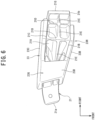
Figure 8] Figure 8 is a view showing the vehicle driving device noise-absorbing structure according to the one embodiment of the present invention and is a perspective view of the right bracket, a front-side noise-absorbing member, a rear-side noise-absorbing member, and a cover member. - [
Figure 9] Figure 9 is a view showing the vehicle driving device noise-absorbing structure according to the one embodiment of the present invention and is an exploded perspective view of the right bracket, the front-side noise-absorbing member and the cover member, and the rear-side noise-absorbing member. - [
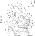
Figure 10] Figure 10 is a sectional schematic view taken along arrows X-X inFigure 2 . - [
Figure 11] Figure 11 is a sectional schematic view taken along arrows XI-XI inFigure 2 . - [
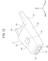
Figure 12] Figure 12 is a view showing the vehicle driving device noise-absorbing structure according to the one embodiment of the present invention and is a perspective view of the front-side noise-absorbing member. - [
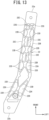
Figure 13] Figure 13 is a view showing the vehicle driving device noise-absorbing structure according to the one embodiment of the present invention and is a bottom view of the right bracket. - A vehicle driving device noise-absorbing structure according to one embodiment of the present invention is a vehicle driving device noise-absorbing structure in which a noise-absorbing member is attached to a bracket for attaching a vehicle driving device to a vehicle body, wherein the noise-absorbing member includes a first noise-absorbing member having a first tubular portion into which the bracket is to be inserted and a first engaging portion which is to be engaged with the bracket, a cover member is arranged on the noise-absorbing member, the cover member has a second tubular portion which covers an outer peripheral portion of the first tubular portion, and the first engaging portion is pushed against the bracket by the second tubular portion.
- With the above-described configuration, the vehicle driving device noise-absorbing structure according to the one embodiment of the present invention can reduce the number of work man-hours to attach a noise-absorbing member to a bracket and enhance work efficiency of the work of attaching the noise-absorbing member.
- A vehicle driving device noise-absorbing structure according to one embodiment of the present invention will be described below with reference to the drawings.
-
Figures 1 to 13 are views showing the vehicle driving device noise-absorbing structure according to the one embodiment of the present invention. InFigures 1 to 13 , up-down, front-rear, and left-right directions are based on a vehicle driving device in a state of being arranged in a vehicle. A vehicle front-rear direction will be referred to as the front-rear direction; a vehicle left-right direction (vehicle width direction) will be referred to as the left-right direction; and a vehicle up-down direction (vehicle height direction) will be referred to as the up-down direction. - A configuration will be described first.
- In
Figure 1 , a vehicle 1 includes aleft side frame 2 and aright side frame 3. Theleft side frame 2 and theright side frame 3 are away from each other in a width direction of the vehicle 1 (hereinafter simply referred to as the vehicle width direction) and extend in the front-rear direction of the vehicle 1. - The
left side frame 2 and theright side frame 3 are connected by afront cross-member 5, acenter cross-member 6, andrear cross-members front cross-member 5, thecenter cross-member 6, and therear cross-members - The
center cross-member 6 is formed in an X-shape in plan view. - A
power train 10 is provided in the vehicle 1. Thepower train 10 has anengine 11 which is an internal combustion engine and atransmission 12 which changes a rotational speed of a crankshaft (not shown) of theengine 11 and produces power output. - The
engine 11 is longitudinally arranged such that a rotation center axis of the crankshaft extends in the front-rear direction of the vehicle 1. - A front end of a
propeller shaft 13 is connected to thetransmission 12, and thepropeller shaft 13 extends from thetransmission 12 toward the rear of the vehicle 1. Atransfer device 14 as a vehicle driving device is arranged behind thetransmission 12, and a rear end of thepropeller shaft 13 is connected to thetransfer device 14. - With the above-described configuration, power of the
engine 11 which is changed in speed by thetransmission 12 is transmitted to thetransfer device 14 via thepropeller shaft 13. - The
transfer device 14 has an input shaft to which the rear end of thepropeller shaft 13 is connected and an output shaft which is arranged in parallel with the input shaft and is coordinated with the input shaft using gears and the like. The input shaft of thetransfer device 14 is longitudinally arranged near the middle in the left-right direction of the vehicle 1 such that a rotation center axis thereof extends in the front-rear direction of the vehicle 1. - The output shaft of the
transfer device 14 is longitudinally arranged to the right of the vehicle 1 and between the input shaft and theright side frame 3 such that a rotation center axis thereof extends in the front-rear direction of the vehicle 1. A rear end of afront propeller shaft 15 is connected to a front end of the output shaft of thetransfer device 14. - A front end of a
rear propeller shaft 16 is connected to a rear end of the output shaft of thetransfer device 14. For this reason, the mass of thetransfer device 14 concentrates on a right-side portion where the output shaft is arranged to affect vibration characteristics. - The
front propeller shaft 15 extends from thetransfer device 14 toward a lateral of thepower train 10 to the front of the vehicle 1. - A front end of the
front propeller shaft 15 is connected to a frontdifferential device 17 which is arranged to the right of and below thepower train 10. The frontdifferential device 17 transmits power of thefront propeller shaft 15 to front wheels (not shown) via left and right drive shafts (not shown) such that the front wheels are capable of differential rotation. - A rear end of the
rear propeller shaft 16 is connected to a rear differential device (not shown). The rear differential device transmits power of therear propeller shaft 16 to rear wheels (not shown) via left and right drive shafts (not shown) such that the rear wheels are capable of differential rotation. - The
transfer device 14 is provided with aselector lever 19. A driver can select among neutral that outputs no driving force, two-wheel drive that drives only the rear wheels, and four-wheel drive that drives the front wheels and the rear wheels by manipulating theselector lever 19. Additionally, a reduction gear ratio can be switched between a high-gear one and a low-gear one. - When the driver manipulates the
selector lever 19, and either one of the two-wheel drive and the four-wheel drive is selected, thetransfer device 14 switches a transmission path between a two-wheel drive state where power transmitted from thepropeller shaft 13 is not transmitted to thefront propeller shaft 15 and a four-wheel drive state where power is also transmitted to thefront propeller shaft 15. - With the above-described configuration, the vehicle 1 constitutes a part-time 4WD vehicle capable of switching between the two-wheel drive and the four-wheel drive. Note that the
transfer device 14 may be configured so as to have a power transmission path which causes the vehicle 1 to be driven with all four wheels full-time, i.e., so as to constitute a full-time 4WD vehicle. - The
left side frame 2 and thetransfer device 14 are connected by aleft bracket 21 made of metal. - The
left bracket 21 extends leftward from thetransfer device 14, and aleft end portion 21a thereof is elastically connected to theleft side frame 2 via a mount member (not shown). - A
right end portion 21b of theleft bracket 21 is fixed to a connectingportion 14B which is formed at a left side surface of acase 14A of thetransfer device 14 with a bolt. Theleft end portion 21a of theleft bracket 21 according to the present embodiment constitutes one end portion of a bracket, and theright end portion 21b of theleft bracket 21 constitutes the other end portion of the bracket. - As shown in
Figure 3 , a connectingportion 21G is provided at theright end portion 21b of theleft bracket 21. The connectingportion 21G has an attachment surface facing to the upper right. The connectingportion 21G is attached to thetransfer device 14 by fixation of the attachment surface to the connectingportion 14B of thecase 14A with a bolt (not shown). - In other words, the connecting
portion 14B, to which the connectingportion 21G of theleft bracket 21 is to be fixed, is provided at the left side surface of thecase 14A of thetransfer device 14. - As shown in
Figure 1 , theright side frame 3 and thetransfer device 14 are connected by aright bracket 22 made of metal. Theright bracket 22 extends in the front-rear direction along theright side frame 3 to the left of theright side frame 3, and an intermediate portion in the front-rear direction is fixed to thetransfer device 14. - A
front end portion 22a of theright bracket 22 is elastically connected to theright side frame 3 via a mount member (not shown), and arear end portion 22b of theright bracket 22 is elastically connected to theright side frame 3 via a mount member (not shown). - The
left side frame 2, theright side frame 3, and thecenter cross-member 6 according to the present embodiment constitute a vehicle body, and theleft bracket 21 and theright bracket 22 constitute a bracket. - As shown in
Figures 4 and6 , theleft bracket 21 includes anupper wall 21A, afront wall 21B which extends downward from a front end edge of theupper wall 21A, and arear wall 21C which extends downward from a rear end edge of theupper wall 21A and is formed in a generally U-shape which opens downward in a section perpendicular to the vehicle width direction. - As shown in
Figures 3 and6 , front-rear direction ribs 21D which extend along the vehicle front-rear direction are formed at an inner surface of theleft bracket 21. The front-rear direction ribs 21D connect thefront wall 21B and therear wall 21C. - A vehicle-
width direction rib 21E which extends along the vehicle left-right direction is formed at the inner surface of theleft bracket 21. The vehicle-width direction rib 21E extends in the vehicle width direction so as to connect the front-rear direction ribs 21D at a middle portion in the front-rear direction between thefront wall 21B and therear wall 21C. - The
left bracket 21 is reinforced with the front-rear direction ribs 21D and the vehicle-width direction rib 21E and thus has high rigidity. - As shown in
Figures 3 and6 , a length in the front-rear direction of theleft bracket 21 is set shorter on theleft side frame 2 side (theleft end portion 21a side) and longer on thetransfer device 14 side (theright end portion 21b side) than on theleft side frame 2 side. - As shown in
Figures 4 ,5 , and7 , aboss portion 21F is provided on theupper wall 21A of theleft bracket 21, and theboss portion 21F protrudes rightward and obliquely upward from theupper wall 21A toward the transfer device 14 (seeFigure 2 ). - In other words, a component attachment surface is formed at the
boss portion 21F, and theboss portion 21F extends obliquely from theupper wall 21A such that the attachment surface protrudes toward thetransfer device 14. - As shown in
Figure 2 , aclamp 41A of aswitch cord 41 is attached to an upper end of theboss portion 21F. Theswitch cord 41 connects thetransfer device 14 and a controller (not shown), and theclamp 41A holds theswitch cord 41 and is attached and fixed to theboss portion 21F using a bolt or the like. - The
switch cord 41 transmits a signal corresponding to a selector position of theselector lever 19 from thetransfer device 14 to the controller. Theboss portion 21F according to the present embodiment constitutes a protruding portion, and theclamp 41A constitutes a predetermined in-vehicle component. - As shown in
Figures 2 and9 , a connectingportion 22F is provided at a left edge portion of a middle portion in the front-rear direction of theright bracket 22 so as to protrude upward. - As shown in
Figure 2 , a connectingportion 14C is provided at a right side surface of thecase 14A of thetransfer device 14, and the connectingportion 22F of theright bracket 22 is fixed to the connectingportion 14C with a bolt (not shown). - As described above, the
transfer device 14 is elastically supported by theleft side frame 2 via theleft bracket 21 and is elastically supported by theright side frame 3 via theright bracket 22. - As shown in
Figures 9 ,10 , and13 , theright bracket 22 has anupper wall 22A, aleft wall 22B which extends downward from a left end edge of theupper wall 22A, and a right wall 22C which extends downward from a right end edge of theupper wall 22A and is formed in a generally U-shape which opens downward in a section perpendicular to the front-rear direction. - As shown in
Figure 13 , a plurality ofinclined ribs 22D are formed between theleft wall 22B and the right wall 22C at an inner surface (lower surface) of theright bracket 22 so as to connect theleft wall 22B and the right wall 22C. Eachinclined rib 22D is inclined with respect to a direction in which theleft wall 22B, the right wall 22C, and theright bracket 22 extend. - The
inclined ribs 22D are formed to cross in an X-shape in bottom view of theright bracket 22. The X-shaped pairs ofinclined ribs 22D are arranged to be continuously lined up in the front-rear direction. - A front-
rear direction rib 22E is provided in the middle in the vehicle width direction between theleft wall 22B and the right wall 22C at a front-side inner surface (lower surface) of theright bracket 22. The front-rear direction rib 22E extends in the same direction as the direction, in which theright bracket 22 extends, so as to connect points where theinclined ribs 22D cross. - As shown in
Figure 9 , the connectingportion 22F protrudes upward from theupper wall 22A of theright bracket 22. A width in the vehicle width direction of theright bracket 22 is formed such that a width on a front side is narrower than a width on a rear side in front of the connectingportion 22F and such that the width on the rear side is wider than the width on the front side. - The width in the vehicle width direction of the
right bracket 22 is also formed such that a width on a front side is wider behind the connectingportion 22F and such that a width on a rear side is narrower than the width on the front side. - In other words, the width in the vehicle width direction of the
right bracket 22 is formed widest at a point near the connectingportion 22F and is formed so as to decrease gradually from near the connectingportion 22F toward thefront end portion 22a or therear end portion 22b. - A length in the front-rear direction of the
right bracket 22 is formed such that a length of a portion behind the connectingportion 22F is shorter than a length of a portion in front of the connectingportion 22F. - As shown in
Figures 2 and3 , a noise-absorbingmember 23 which is made of an elastic member, such as polyurethane rubber, is attached to theleft bracket 21. - The noise-absorbing
member 23 has anupper wall 23A which is in contact with theupper wall 21A of theleft bracket 21, afront wall 23B which extends downward from a front end edge of theupper wall 23A and is in contact with thefront wall 21B of theleft bracket 21, and arear wall 23C which extends downward from a rear end edge of theupper wall 23A and is in contact with therear wall 21C of theleft bracket 21. - In other words, the noise-absorbing
member 23 covers theleft bracket 21 from above and is in contact with all surfaces to suppress vibration of theleft bracket 21 and inhibit emission of noise to a space with a passenger compartment above the noise-absorbingmember 23. A length in the front-rear direction of the noise-absorbingmember 23 is formed shorter on theleft side frame 2 side and longer on thetransfer device 14 side than on theleft side frame 2 side, as in theleft bracket 21. - As shown in
Figures 6 and7 , atubular portion 23G is provided at a left-side portion of the noise-absorbingmember 23. Thetubular portion 23G is configured to include a left end portion of theupper wall 23A, a left end portion of thefront wall 23B, a left end portion of therear wall 23C, and abottom wall 23D which connects a lower end portion of the left end portion of thefront wall 23B and a lower end portion of the left end portion of therear wall 23C. - In other words, the
tubular portion 23G is configured to include theupper wall 23A, thefront wall 23B, therear wall 23C, and thebottom wall 23D, is arranged to surround an outer peripheral portion on theleft end portion 21a side of theleft bracket 21 and is in contact with an outer peripheral portion of theleft bracket 21. - The
tubular portion 23G, in which theleft bracket 21 is inserted, is formed such that an inner dimension (open width) on theleft end portion 21a side of theleft bracket 21 is smaller than an inner dimension (open width) on theright end portion 21b side (thetransfer device 14 side) of theleft bracket 21. - For the above-described reason, the noise-absorbing
member 23 is configured to be attachable to and detachable from theleft bracket 21 attached to thetransfer device 14, from theleft end portion 21a side of theleft bracket 21. - The noise-absorbing
member 23 includes a noise-absorbingmember body portion 23H. The noise-absorbingmember body portion 23H is composed of theupper wall 23A, thefront wall 23B, and therear wall 23C, excluding thetubular portion 23G, of the noise-absorbingmember 23 and extends from thetubular portion 23G along theleft bracket 21 to thetransfer device 14. - In other words, the noise-absorbing
member body portion 23H extends from thetubular portion 23G along theleft bracket 21 in a direction in which theleft bracket 21 extends. - As shown in
Figure 4 , the noise-absorbingmember body portion 23H is formed in a generally U-shape which opens downward in a section perpendicular to the vehicle width direction. Theupper wall 23A, thefront wall 23B, and therear wall 23C of the noise-absorbingmember body portion 23H are in contact with theupper wall 21A, thefront wall 21B, and therear wall 21C of theleft bracket 21. - In other words, a lower side of the noise-absorbing
member body portion 23H is open, and a lower surface of theleft bracket 21 is not covered by the noise-absorbingmember body portion 23H even in a state where the noise-absorbingmember body portion 23H is attached. - In other words, a portion on the
right end portion 21b side of theleft bracket 21 is covered by the noise-absorbingmember body portion 23H from above. The contact suppresses vibration of the portion and inhibits emission of noise to the space with the passenger compartment above the portion. - As shown in
Figure 1 , anexhaust pipe 42 is provided in the vehicle 1. Theexhaust pipe 42 extends rearward from a portion to the left of theengine 11 in a left-side portion of the vehicle 1 and discharges exhaust gas discharged from theengine 11 to behind the vehicle 1. Acatalyst 43 and asilencer 44 are attached to theexhaust pipe 42, thecatalyst 43 cleans up exhaust, and thesilencer 44 muffles exhaust noise. - As shown in
Figures 1 and2 , theexhaust pipe 42 passes below theleft bracket 21 in the front-rear direction, and the noise-absorbingmember body portion 23H is located above theexhaust pipe 42. That is, thebottom wall 23D is not arranged above theexhaust pipe 42, and thetubular portion 23G and theexhaust pipe 42 are away from each other in the vehicle width direction in top view. - In other words, in the
left bracket 21 located directly above theexhaust pipe 42, a lower side is not covered by the noise-absorbingmember body portion 23H and is naked to theexhaust pipe 42. Theleft bracket 21 is directly exposed to heat of theexhaust pipe 42. - In the up-down direction, the noise-absorbing
member 23 is not directly opposed to theexhaust pipe 42, and hot air rising from theexhaust pipe 42 is prevented from acting directly. - As shown in
Figures 4 and5 , ahole 23a is formed in theupper wall 23A of the noise-absorbingmember body portion 23H. Theboss portion 21F of theleft bracket 21 is inserted in thehole 23a and protrudes from thehole 23a to outside the noise-absorbingmember 23. The noise-absorbingmember 23 is engaged with theboss portion 21F at thehole 23a. - As shown in
Figure 2 , a width in the vehicle width direction of theclamp 41A of theswitch cord 41 is set larger than a width in the vehicle width direction of thehole 23a. That is, theclamp 41A that has a larger width in the vehicle width direction than the width in the vehicle width direction of thehole 23a is attached to theboss portion 21F. This inhibits the noise-absorbingmember 23 from coming off theboss portion 21F. - A
fitting portion 21f (seeFigures 4 and5 ) on which theclamp 41A is to be fit is formed at theboss portion 21F. Thefitting portion 21f serves for positioning which restricts a posture of theclamp 41A, and theclamp 41A does not come off theboss portion 21F even if a large external force is applied to theclamp 41A. - As shown in
Figures 4 and5 , a thin-plate portion 23E is formed over a range from thehole 23a to a right-side end edge at theupper wall 23A of the noise-absorbingmember body portion 23H on thetransfer device 14 side. The thin-plate portion 23E is formed to have a thickness smaller than a thickness of theupper wall 23A (seeFigure 7 ). The thin-plate portion 23E is located below an upper surface of theupper wall 23A of the noise-absorbingmember body portion 23H. - As shown in
Figure 4 , a left edge of the thin-plate portion 23E constitutes a part of a peripheral edge of thehole 23a. That is, thehole 23a is surrounded by theupper wall 23A of the noise-absorbingmember body portion 23H and the left edge of the thin-plate portion 23E. - As shown in
Figure 5 , front and rear portions of the thin-plate portion 23E are connected to theupper wall 23A of the noise-absorbingmember body portion 23H by afront end portion 23b and arear end portion 23c. Aslit 23s which extends in the vehicle width direction from thehole 23a to a right-side end edge is formed in a middle portion in the front-rear direction of the thin-plate portion 23E. - If the
boss portion 21F and thehole 23a get closer together, and theboss portion 21F comes into contact with the thin-plate portion 23E when the noise-absorbingmember 23 is attached to theleft bracket 21, theboss portion 21F pushes the thin-plate portion 23E upward. The thin-plate portion 23E is elastically deformed so as to open theslit 23s of the thin-plate portion 23E, which causes theboss portion 21F to pass through the thin-plate portion 23E. Theboss portion 21F can be easily inserted into thehole 23a. - In other words, the thin-
plate portion 23E is easily elastically deformed when an external force which inserts theboss portion 21F into thehole 23a is applied at the time of assembly of the noise-absorbingmember 23 to theleft bracket 21. After the noise-absorbingmember 23 is assembled to theleft bracket 21, the thin-plate portion 23E returns to its original position, slips beneath a lower right side of theboss portion 21F, and engages with theboss portion 21F (seeFigure 7 ). - The thin-
plate portion 23E has such a high hardness that the thin-plate portion 23E is not deformed even when vibration is applied from theleft bracket 21 to the noise-absorbingmember 23 due to, e.g., running of the vehicle 1. - As shown in
Figures 8 and9 , a front-side noise-absorbingmember 24 which is made of an elastic member, such as polyurethane rubber, is attached to theright bracket 22 in front of the connectingportion 22F. - As shown in
Figures 8 ,11 , and12 , the front-side noise-absorbingmember 24 includes anupper wall 24A which is in contact with theupper wall 22A of theright bracket 22, aleft wall 24B which extends downward from a left end edge of theupper wall 24A and is in contact with theleft wall 22B of theright bracket 22, aright wall 24C which extends downward from a right end edge of theupper wall 24A and is in contact with the right wall 22C of theright bracket 22, and abottom wall 24D which connects a lower end portion of theleft wall 24B and a lower end portion of theright wall 24C. - The
upper wall 24A, theleft wall 24B, theright wall 24C, and thebottom wall 24D are in contact with an outer peripheral portion of theright bracket 22 so as to surround the outer peripheral portion of theright bracket 22 on a front side of the front-side noise-absorbingmember 24 and constitute atubular portion 24E. Thetubular portion 24E according to the present embodiment constitutes a first tubular portion according to the present invention. - In other words, the
right bracket 22 is surrounded by the front-side noise-absorbingmember 24. The contact suppresses vibration of theright bracket 22 and inhibits emission of noise. - The
tubular portion 24E, in which theright bracket 22 is inserted, is formed such that an inner dimension (open width) on thefront end portion 22a side of theright bracket 22 is smaller than an inner dimension (open width) on the connectingportion 22F side (thetransfer device 14 side) of theright bracket 22. - For the above-described reason, the front-side noise-absorbing
member 24 is configured to be attachable to and detachable from theright bracket 22 attached to thetransfer device 14, from thefront end portion 22a side of theright bracket 22. - As shown in
Figure 12 , the front-side noise-absorbingmember 24 has a rear-side bottom wall 24F which extends rearward from thetubular portion 24E so as to extend thebottom wall 24D, a rear-sideleft wall 24G which protrudes upward from a left end edge of the rear-side bottom wall 24F and extends rearward so as to extend theleft wall 24B of thetubular portion 24E, and a rear-sideright wall 24H which protrudes upward from a right end edge of the rear-side bottom wall 24F and extends rearward so as to extend theright wall 24C of thetubular portion 24E. - The rear-
side bottom wall 24F covers a lower side of theright bracket 22, the rear-sideleft wall 24G is in contact with theleft wall 22B of theright bracket 22, and the rear-sideright wall 24H is in contact with the right wall 22C of theright bracket 22. - In other words, the rear-
side bottom wall 24F, the rear-sideleft wall 24G, and the rear-sideright wall 24H are in contact with the outer peripheral portion excluding theupper wall 22A of theright bracket 22, the front-side noise-absorbingmember 24 has no upper wall behind thetubular portion 24E, and theupper wall 22A of theright bracket 22 is exposed between the rear-sideleft wall 24G and the rear-sideright wall 24H (seeFigure 8 ). - Heights of the rear-side
left wall 24G and the rear-sideright wall 24H are formed lower than heights of theleft wall 24B and theright wall 24C of thetubular portion 24E. - As shown in
Figures 9 and12 , lengths in the front-rear direction of the rear-side bottom wall 24F and the rear-sideright wall 24H are formed equal, and a length in the front-rear direction of the rear-sideleft wall 24G is formed longer than the lengths in the front-rear direction of the rear-side bottom wall 24F and the rear-sideright wall 24H. - In other words, the rear-side
left wall 24G extends so as to protrude rearward further than the rear-side bottom wall 24F and the rear-sideright wall 24H. For this reason, a lower portion of the rear-sideleft wall 24G has a shape notched by an amount corresponding to a height of the rear-side bottom wall 24F, and a rear-side lower surface of the rear-sideleft wall 24G has almost the same height position as an upper surface of the rear-side bottom wall 24F. - A width in the vehicle width direction of the front-side noise-absorbing
member 24 is formed wider on a rear side and narrower on the front side (thetubular portion 24E side) than on the rear side. Thefront end portion 22a of theright bracket 22 that is narrower in a width in the vehicle width direction than the connectingportion 22F is inserted in thetubular portion 24E on the front side. - As shown in
Figure 12 , one pair of engagingprojections 241 is formed at a front end portion of thebottom wall 24D of thetubular portion 24E. The engaging projections 24I protrude upward from thebottom wall 24D. That is, the engaging projections 24I protrude from thebottom wall 24D inside thetubular portion 24E. - As shown in
Figure 13 , one pair ofgroove portions 22G is formed between theinclined ribs 22D on thefront end portion 22a side of theright bracket 22 and the front-rear direction rib 22E, and the engaging projections 24I are engaged with thegroove portions 22G (seeFigure 11 ). - Specifically, the one pair of engaging projections 24I is in the one pair of
groove portions 22G, holds the front-rear direction rib 22E therebetween, and is engaged with theright bracket 22 with perimeters thereof in contact with theright bracket 22. - For the above-described reason, the engaging projections 24I catch in the
groove portions 22G in a state where thetubular portion 24E of the front-side noise-absorbingmember 24 is attached to theright bracket 22. This prevents the front-side noise-absorbingmember 24 from coming off theright bracket 22 and prevents theright bracket 22 from coming off the front-side noise-absorbingmember 24. - In other words, the front-side noise-absorbing
member 24 is put into a pierced state by insertion of theright bracket 22 into thetubular portion 24E. With engagement of the engaging projections 24I with thegroove portions 22G, the front-side noise-absorbingmember 24 is attached to theright bracket 22 in a state of being stopped from coming off theright bracket 22. - For the above-described reason, combined with effects of a shape of the
tubular portion 24E, the front-side noise-absorbingmember 24 is prevented from coming off theright bracket 22. - As shown in
Figure 11 , the engaging projections 24I protrude forward from a front end portion of thetubular portion 24E, and the engaging projections 24I engage with thegroove portions 22G in a compressed state. This maintains a contact pressure between the engaging projections 24I and thegroove portions 22G high. - As shown in
Figures 8 and9 , a rear-side noise-absorbingmember 25 which is made of an elastic member, such as polyurethane rubber, is attached to theright bracket 22 behind the connectingportion 22F, and the connectingportion 22F is located between the front-side noise-absorbingmember 24 and the rear-side noise-absorbingmember 25 in the front-rear direction. The front-side noise-absorbingmember 24 according to the present embodiment constitutes a first noise-absorbing member, and the rear-side noise-absorbingmember 25 constitutes a second noise-absorbing member. - The rear-side noise-absorbing
member 25 includes anupper wall 25A which is in contact with theupper wall 22A of theright bracket 22, aleft wall 25B which extends downward from a left end edge of theupper wall 25A and is in contact with theleft wall 22B of theright bracket 22, aright wall 25C which extends downward from a right end edge of theupper wall 25A and is in contact with the right wall 22C of theright bracket 22, and abottom wall 25D which connects a lower end portion of theleft wall 25B and a lower end portion of theright wall 25C. - The
upper wall 25A, theleft wall 25B, theright wall 25C, and thebottom wall 25D are in contact with the outer peripheral portion of theright bracket 22 so as to surround the outer peripheral portion of theright bracket 22 on a rear side of the rear-side noise-absorbingmember 25 and constitute atubular portion 25E. Thetubular portion 25E according to the present embodiment constitutes a third tubular portion. - In other words, the
right bracket 22 is surrounded by the rear-side noise-absorbingmember 25. The contact suppresses vibration of theright bracket 22 and inhibits emission of noise. - The
tubular portion 25E, in which theright bracket 22 is inserted, is formed such that an inner dimension (open width) on therear end portion 22b side of theright bracket 22 is formed smaller than an inner dimension (open width) on the connectingportion 22F side (thetransfer device 14 side) of theright bracket 22. - For the above-described reason, the rear-side noise-absorbing
member 25 is configured to be attachable to and detachable from theright bracket 22 attached to thetransfer device 14, from therear end portion 22b side of theright bracket 22. - As shown in
Figure 9 , the rear-side noise-absorbingmember 25 has a front-side bottom wall 25F which extends forward from thebottom wall 25D of thetubular portion 25E and a front-sideright wall 25G which protrudes upward from a right end edge of the front-side bottom wall 25F and extends forward so as to extend theright wall 25C of thetubular portion 25E. - The front-
side bottom wall 25F and the front-sideright wall 25G are in contact with the outer peripheral portion of theright bracket 22, and the rear-side noise-absorbingmember 25 has no upper wall and no left wall in front of thetubular portion 25E. To the left of the front-sideright wall 25G, theupper wall 22A of theright bracket 22 is exposed. - In other words, as shown in
Figures 10 and11 , front ends of the front-side bottom wall 25F and the front-sideright wall 25G reach a position of the connectingportion 22F of theright bracket 22, and the front-side bottom wall 25F and the front-sideright wall 25G, together with the rear-side bottom wall 24F and the rear-sideright wall 24H of the front-side noise-absorbingmember 24, cover a portion below the connectingportion 22F and a portion to the right of the connectingportion 22F. - As shown in
Figure 9 , one pair of engagingprojections 25H is formed at a rear end portion of thebottom wall 25D of thetubular portion 25E, and the engagingprojections 25H protrude upward from thebottom wall 25D. That is, the engagingprojections 25H protrude from thebottom wall 25D inside thetubular portion 25E. - As shown in
Figure 13 , one pair ofgroove portions 22H is formed between a rear end portion of theinclined rib 22D and theleft wall 22B of theright bracket 22 and between a rear end portion of theinclined rib 22D and the right wall 22C of theright bracket 22 on therear end portion 22b side of theright bracket 22. The engagingprojections 25H are engaged with thegroove portions 22H (seeFigure 11 ). - For the above-described reason, the engaging
projections 25H catch in thegroove portions 22H in a state where thetubular portion 25E of the rear-side noise-absorbingmember 25 is attached to theright bracket 22. With this configuration, the rear-side noise-absorbingmember 25 is attached to theright bracket 22 in a state of being stopped from coming off theright bracket 22. - In other words, insertion of the
right bracket 22 into thetubular portion 25E puts the rear-side noise-absorbingmember 25 into a pierced state. With entry of the engagingprojections 25H into thegroove portions 22H and engagement of the engagingprojections 25H with thegroove portions 22H, the rear-side noise-absorbingmember 25 is attached to theright bracket 22 in a state of being stopped from coming off theright bracket 22. - For the above-described reason, combined with effects of a shape of the
tubular portion 25E, the rear-side noise-absorbingmember 25 is prevented from coming off theright bracket 22. The engagingprojections 25H according to the present embodiment constitute a second engaging portion. - As shown in
Figure 11 , the engagingprojections 25H protrude rearward from a rear end portion of thetubular portion 25E, and the engagingprojections 25H engage with thegroove portions 22H in a compressed state. This maintains a contact pressure between the engagingprojections 25H and thegroove portions 22H high. - As shown in
Figure 8 , an in-vehicle component mount 22I is provided on therear end portion 22b side of theright bracket 22, and the in-vehicle component mount 22I is provided behind the rear-side noise-absorbingmember 25. - For example, a fuel pipe clamp (not shown) as an in-vehicle component is attached to the in-vehicle component mount 22I.
- When the rear-side noise-absorbing
member 25 tries to move rearward, the rear-side noise-absorbingmember 25 comes into contact with an in-vehicle component attached to the in-vehicle component mount 22I. This restricts rearward movement of the rear-side noise-absorbingmember 25. The rear-side noise-absorbingmember 25 is stopped from coming off by the in-vehicle component. - As shown in
Figures 8 and9 , acover member 26 made of resin is attached to theright bracket 22 so as to cover the front-side noise-absorbingmember 24. - The
cover member 26 includes anupper wall 26A which is in contact with theupper wall 24A of the front-side noise-absorbingmember 24, aleft wall 26B which extends downward from a left end edge of theupper wall 26A and is in contact with theleft wall 24B of the front-side noise-absorbingmember 24, aright wall 26C which extends downward from a right end edge of theupper wall 26A and is in contact with theright wall 24C of the front-side noise-absorbingmember 24, and abottom wall 26D (seeFigure 3 ) which connects a lower end portion of theleft wall 26B and a lower end portion of theright wall 26C. - The
upper wall 26A, theleft wall 26B, theright wall 26C, and thebottom wall 26D are in contact with an outer peripheral portion of the front-side noise-absorbingmember 24 so as to surround the outer peripheral portion of the front-side noise-absorbingmember 24 at a front-side portion of thecover member 26 and constitute atubular portion 26E. Thetubular portion 26E according to the present embodiment constitutes a second tubular portion. - The
tubular portion 26E of thecover member 26 covers the whole of thetubular portion 24E of the front-side noise-absorbingmember 24, and a length in the front-rear direction of thetubular portion 26E is formed as a length just enough to maintain a position and a posture along theright bracket 22. - The
tubular portion 26E, in which the front-side noise-absorbingmember 24 is inserted, is formed such that an inner dimension (open width) on thefront end portion 22a side of theright bracket 22 is smaller than an inner dimension (open width) on the connectingportion 22F side (thetransfer device 14 side) of theright bracket 22. - For the above-described reason, the
cover member 26 is configured to be attachable to and detachable from the front-side noise-absorbingmember 24 attached to theright bracket 22, from thefront end portion 22a side of theright bracket 22. - As shown in
Figure 9 , thecover member 26 has a rear-side bottom wall 26F which extends rearward from thetubular portion 26E and is in contact with the rear-side bottom wall 24F of the front-side noise-absorbingmember 24, a rear-sideleft wall 26G which protrudes upward from a left end edge of the rear-side bottom wall 26F, extends rearward so as to extend theleft wall 26B of thetubular portion 26E, and is in contact with the rear-sideleft wall 24G of the front-side noise-absorbingmember 24, and a rear-sideright wall 26H which protrudes upward from a right end edge of the rear-side bottom wall 26F, extends rearward so as to extend theright wall 26C of thetubular portion 26E, and is in contact with the rear-sideright wall 24H of the front-side noise-absorbingmember 24. - The
cover member 26 has no upper wall behind thetubular portion 26E, and theupper wall 22A of theright bracket 22 is exposed between the rear-sideleft wall 26G and the rear-sideright wall 26H. - Heights of the rear-side
left wall 26G and the rear-sideright wall 26H are formed lower than heights of theleft wall 26B and theright wall 26C of thetubular portion 26E. - Lengths in the front-rear direction of the rear-
side bottom wall 26F, the rear-sideleft wall 26G, and the rear-sideright wall 26H are formed equal, and the rear-side bottom wall 26F, the rear-sideleft wall 26G, and the rear-sideright wall 26H extend rearward further than the rear-side bottom wall 24F, the rear-sideleft wall 24G, and the rear-sideright wall 24H of the front-side noise-absorbingmember 24. - As shown in
Figure 11 , a rear end portion of the rear-side bottom wall 24F of the front-side noise-absorbingmember 24 and a front end portion of the front-side bottom wall 25F of the rear-side noise-absorbingmember 25 are in contact such that shapes thereof are continuous. - The rear-
side bottom wall 26F of thecover member 26 is arranged beneath the rear-side bottom wall 24F and the front-side bottom wall 25F of the rear-side noise-absorbingmember 25, and thecover member 26 covers over a gap between the rear-side bottom wall 24F and the front-side bottom wall 25F and supports the rear-side bottom wall 24F and the front-side bottom wall 25F from below. - As shown in
Figure 10 , a rear end portion of the rear-sideright wall 24H of the front-side noise-absorbingmember 24 and a front end portion of the front-sideright wall 25G of the rear-side noise-absorbingmember 25 are in contact. That is, a rear end portion of the front-side noise-absorbingmember 24 and a front end portion of the rear-side noise-absorbingmember 25 are in contact such that shapes thereof are continuous. - A gap in the up-down direction is formed between the rear-side
left wall 24G and the rear-side bottom wall 26F of thecover member 26, and the front-side bottom wall 25F of the rear-side noise-absorbingmember 25 lies beneath the rear-sideleft wall 24G of the front-side noise-absorbingmember 24. That is, the front-side bottom wall 25F of the rear-side noise-absorbingmember 25 is arranged between the rear-sideleft wall 24G and the rear-side bottom wall 26F of thecover member 26. - The connecting
portion 14C of thecase 14A of thetransfer device 14 protrudes above thecover member 26 and is opposed to thecover member 26 in the up-down direction. The rear-sideleft wall 24G of the front-side noise-absorbingmember 24 and the front-side bottom wall 25F of the rear-side noise-absorbingmember 25 are arranged between the rear-side bottom wall 26F of thecover member 26 and thecase 14A in the up-down direction and are prevented from coming off. - In other words, the rear-side
left wall 24G of the front-side noise-absorbingmember 24, the front-side bottom wall 25F of the rear-side noise-absorbingmember 25, the rear-side bottom wall 26F of thecover member 26, and thecase 14A are arranged to be lined up in the up-down direction. - As shown in
Figures 8 and10 , the rear-sideright wall 26H of thecover member 26 covers the rear end portion of the rear-sideright wall 24H of the front-side noise-absorbingmember 24 and the front end portion of the front-sideright wall 25G of the rear-side noise-absorbingmember 25. - That is, the rear-side
right wall 26H of thecover member 26 covers a point of contact between the rear-sideright wall 24H of the front-side noise-absorbingmember 24 and the front-sideright wall 25G of the rear-side noise-absorbingmember 25. - In the front-side noise-absorbing
member 24, the rear-side bottom wall 24F, the rear-sideleft wall 24G, and the rear-sideright wall 24H that are U-shaped extend rearward from thetubular portion 24E below the connectingportion 22F of theright bracket 22. The rear-side bottom wall 24F, the rear-sideleft wall 24G, and the rear-sideright wall 24H may droop down. - However, the rear-
side bottom wall 24F, the rear-sideleft wall 24G, and the rear-sideright wall 24H are covered from below by thecover member 26 higher in rigidity than the front-side noise-absorbingmember 24. The covering supports the rear-side bottom wall 24F, the rear-sideleft wall 24G, and the rear-sideright wall 24H, which can be prevented from drooping down. - It is thus possible to prevent the front-side noise-absorbing
member 24 from coming off theright bracket 22 and from being elastically deformed to deteriorate in durability. - Note that a posture of the
cover member 26 is retained by thetubular portion 26E composed of theupper wall 26A, theleft wall 26B, theright wall 26C, and thebottom wall 26D being in contact with the front-side noise-absorbingmember 24 so as to surround the outer peripheral portion of the front-side noise-absorbingmember 24. - As shown in
Figures 10 and11 , ahole 26a is formed in theupper wall 26A of thecover member 26. An engagingprojection 24J is formed on theupper wall 24A of the front-side noise-absorbingmember 24, and the engagingprojection 24J protrudes outward from thehole 26a. With engagement of thehole 26a with the engagingprojection 24J, thecover member 26 is stopped from coming off the front-side noise-absorbingmember 24. Thehole 26a according to the present embodiment constitutes an engaging portion. - An
inclined surface 24t is formed at an upper surface of the engagingprojection 24J, and theinclined surface 24t is inclined upward so as to increase in height from a front end portion on thefront end portion 22a side of theright bracket 22 toward a rear end portion on therear end portion 22b side of theright bracket 22. The engagingprojection 24J according to the present embodiment constitutes a protruding portion. - Since the
tubular portion 26E is formed such that the inner dimension (open width) on thefront end portion 22a side of theright bracket 22 is smaller than the inner dimension (open width) on the connectingportion 22F side (thetransfer device 14 side) of theright bracket 22, if thecover member 26 tries to move rearward, thecover member 26 cannot move rearward further than in an attached state where thecover member 26 is in contact with the front-side noise-absorbingmember 24. - If the
cover member 26 tries to move toward thefront end portion 22a side of theright bracket 22 with respect to the front-side noise-absorbingmember 24, thehole 26a comes into contact with a rear end portion which is highest of the engagingprojection 24J. This reliably stops thecover member 26 from coming off the front-side noise-absorbingmember 24. The engagingprojection 24J according to the present embodiment constitutes a first engaging portion. - As shown in
Figure 10 , anotch hole 26b is formed in a lower portion of theright wall 26C of thecover member 26. An engagingprojection 24K which is long in the front-rear direction is formed on theright wall 24C of the front-side noise-absorbingmember 24, and the engagingprojection 24K is fitted in thenotch hole 26b. - For the above-described reason, combined with engagement with the first engaging portion, the
cover member 26 is effectively stopped from coming off the front-side noise-absorbingmember 24. - As shown in
Figure 11 , thetubular portion 26E of thecover member 26 covers points of engagement between the engaging projections 24I of the front-side noise-absorbingmember 24 and thegroove portions 22G of theright bracket 22, and the front-side noise-absorbingmember 24 is surrounded by thetubular portion 26E. For this reason, the engaging projections 24I are less likely to move so as to get out of thegroove portions 22G, and a state where the engaging projections 24I are engaged with thegroove portions 22G is maintained. - Action of a noise-absorbing structure for the
transfer device 14 according to the present embodiment will be described. - As for the noise-absorbing
member 23 according to the present embodiment, in a state before theleft bracket 21 is mounted on the vehicle 1, thetubular portion 23G is inserted into theleft bracket 21 fixed to thetransfer device 14 from theleft end portion 21a, and theboss portion 21F is inserted into thehole 23a while theleft end portion 21a side of theleft bracket 21 is grasped with thetubular portion 23G. - When the
boss portion 21F is inserted into thehole 23a, theboss portion 21F comes into contact with the thin-plate portion 23E, and the thin-plate portion 23E is deformed so as to open theslit 23s. This allows theboss portion 21F to be easily inserted into thehole 23a. - A width in the front-rear direction of the
left bracket 21 is formed narrower on theleft side frame 2 side and wider on thetransfer device 14 side than on theleft side frame 2 side. A width in the front-rear direction of the noise-absorbingmember 23 is formed narrower on theleft side frame 2 side and wider on thetransfer device 14 side than on theleft side frame 2 side. - For the above-described reason, in a state where the noise-absorbing
member 23 is attached to theleft bracket 21, the noise-absorbingmember 23 is capable of moving toward theleft side frame 2 side along theleft bracket 21 but is incapable of moving toward thetransfer device 14 side. - As for the noise-absorbing
member 23 and theleft side frame 2, engagement of theboss portion 21F of theleft bracket 21 with thehole 23a of theupper wall 23A of the noise-absorbingmember body portion 23H stops the noise-absorbingmember 23 from coming off theleft bracket 21 and makes the noise-absorbingmember 23 incapable of moving toward theleft side frame 2 side with respect to theleft bracket 21. - If vibration transmitted from the
transfer device 14 to theleft bracket 21 drives the noise-absorbingmember 23 to come off theleft bracket 21, the noise-absorbingmember 23 may pivot about thetubular portion 23G such that thehole 23a side (a right side) is lifted upward, as shown inFigure 7 . - In the above-described case, the
boss portion 21F of theleft bracket 21 engages with thehole 23a of the noise-absorbingmember body portion 23H, which blocks the noise-absorbingmember 23 from moving leftward and upward. - In other words, the noise-absorbing
member 23 is put into a pierced state by insertion of theleft bracket 21 into thetubular portion 23G. With engagement of theboss portion 21F with thehole 23a, the noise-absorbingmember 23 is attached to theleft bracket 21 in a state of being stopped from coming off theleft bracket 21. - Additionally, upon occurrence of a pivot about the
tubular portion 23G which lifts up the right side, theboss portion 21F of theleft bracket 21 engages effectively with thehole 23a to block leftward and upward movement of the noise-absorbingmember 23. - With the above-described configuration, it is possible to prevent the noise-absorbing
member 23 from coming off theleft bracket 21 when vibration is applied from thetransfer device 14 to theleft bracket 21 and stably attach the noise-absorbingmember 23 to theleft bracket 21. - As a result, noise caused by vibration transmitted from the
transfer device 14 to theleft bracket 21 can be absorbed by the noise-absorbingmember 23, and noise emanating from thetransfer device 14 can be reduced. - The front-side noise-absorbing
member 24 is put into a pierced state by insertion of theright bracket 22 into thetubular portion 24E. With engagement of the engaging projections 24I with thegroove portions 22G, the front-side noise-absorbingmember 24 is attached to theright bracket 22 in a state of being stopped from coming off theright bracket 22. - The rear-side noise-absorbing
member 25 is put into a pierced state by insertion of theright bracket 22 into thetubular portion 25E of the rear-side noise-absorbingmember 25. With engagement of the engagingprojections 25H with thegroove portions 22H, the rear-side noise-absorbingmember 25 is attached to theright bracket 22 in a state of being stopped from coming off theright bracket 22. - Thus, noise caused by vibration transmitted from the
transfer device 14 to theright bracket 22 can be absorbed by the front-side noise-absorbingmember 24 and the rear-side noise-absorbingmember 25, and noise emanating from thetransfer device 14 can be reduced. - As a result, noise emanating from the
transfer device 14 can be reduced by the noise-absorbingmember 23, the front-side noise-absorbingmember 24, and the rear-side noise-absorbingmember 25, and quietness of the vehicle 1 can be enhanced. - The
right bracket 22 is arranged so as to extend in the front-rear direction along theright side frame 3 near theright side frame 3 extending in the front-rear direction. Snow is likely to accumulate on an upper portion of theright bracket 22 in winter. Water raised by the front wheels or the like due to running comes from below to theright bracket 22. - When snow accumulated on the
right bracket 22 melts, the snow turns into water. When the water gets cold, the water turns into ice. The front-side noise-absorbingmember 24 and the rear-side noise-absorbingmember 25 are thus exposed to a harsh environment. - Since water expands when the water freezes, water in a gap between the
right bracket 22 and the front-side noise-absorbingmember 24, a gap between theright bracket 22 and the rear-side noise-absorbingmember 25, and a gap between the front-side noise-absorbingmember 24 and the rear-side noise-absorbingmember 25 becomes an obstacle to the front-side noise-absorbingmember 24 and the rear-side noise-absorbingmember 25 that are made of relatively soft materials. - In the noise-absorbing structure for the
transfer device 14 according to the present embodiment, thecover member 26 made of resin that is harder than the front-side noise-absorbingmember 24 is attached to the front-side noise-absorbingmember 24, the rear-sideright wall 26H of thecover member 26 covers the point of contact between the rear-sideright wall 24H of the front-side noise-absorbingmember 24 and the front-sideright wall 25G of the rear-side noise-absorbingmember 25, and the rear-side bottom wall 26F of thecover member 26 covers the point of contact between the rear-side bottom wall 24F of the front-side noise-absorbingmember 24 and the front-side bottom wall 25F of the rear-side noise-absorbingmember 25. - With the above-described configuration, snow and water can be prevented from penetrating into the gap between the
right bracket 22 and the front-side noise-absorbingmember 24, the gap between theright bracket 22 and the rear-side noise-absorbingmember 25, and a gap between the rear-side bottom wall 24F and the front-side bottom wall 25F and turning into ice, and the front-side noise-absorbingmember 24 and the rear-side noise-absorbingmember 25 can be protected from snow and ice. - In addition, since the
tubular portion 24E of the front-side noise-absorbingmember 24 is covered by thetubular portion 26E of thecover member 26, the front-side noise-absorbingmember 24 can be protected from snow, an incoming stone from ahead, and the like. - The engaging projections 24I are formed at the
tubular portion 24E of the front-side noise-absorbingmember 24, and the engaging projections 24I are elastically deformed in a state of being engaged with thegroove portions 22G. This maintains the contact pressure between the engaging projections 24I and thegroove portions 22G high. - The engaging
projections 25H are formed at thetubular portion 25E of the rear-side noise-absorbingmember 25, and the engagingprojections 25H are elastically deformed in a state of being engaged with thegroove portions 22H. This maintains the contact pressure between the engagingprojections 25H and thegroove portions 22H high. - For the above-described reason, the engaging
projections 24I and 25H can prevent snow from penetrating into between the front-side noise-absorbingmember 24 and theright bracket 22 and between the rear-side noise-absorbingmember 25 and theright bracket 22 and turning into ice, and the front-side noise-absorbingmember 24 and the rear-side noise-absorbingmember 25 can be protected from snow. - The
exhaust pipe 42 is arranged below theleft bracket 21. As for the noise-absorbingmember 23 attached to theleft bracket 21, snow deposited on the noise-absorbingmember 23 is melted by heat of theexhaust pipe 42. Thus, the noise-absorbingmember 23 is at low risk of being damaged by icing. - Although the noise-absorbing
member body portion 23H of the noise-absorbingmember 23 and theexhaust pipe 42 are opposed to each other in the up-down direction, the noise-absorbingmember body portion 23H is open at a lower surface, and the lower surface of theleft bracket 21 is not covered by the noise-absorbingmember body portion 23H. It is thus possible to inhibit the noise-absorbingmember body portion 23H from being affected by heat of theexhaust pipe 42 and protect the noise-absorbingmember 23 from exhaust heat. - Since the
left bracket 21 is naked above theexhaust pipe 42, heat of theexhaust pipe 42 allows transmission of heat to theleft bracket 21 made of metal, and snow deposited on theleft bracket 21 can be easily melted. - In other words, the noise-absorbing
member 23 is formed in a shape capable of easily melting snow deposited on theleft bracket 21 while preventing direct exposure to heat of theexhaust pipe 42. - Effects of the noise-absorbing structure for the
transfer device 14 according to the present embodiment will be described. - In the noise-absorbing structure for the
transfer device 14 according to the present embodiment, the front-side noise-absorbingmember 24 has thetubular portion 24E, into which theright bracket 22 is to be inserted, and the engaging projections 24I that are to be engaged with theright bracket 22. - With the above-described configuration, the front-side noise-absorbing
member 24 can be easily attached to theright bracket 22 by inserting theright bracket 22 into thetubular portion 24E and engaging the engaging projections 24I with theright bracket 22. - It is thus possible to reduce the number of work man-hours to attach the front-side noise-absorbing
member 24 to theright bracket 22 and enhance work efficiency of the work of attaching the front-side noise-absorbingmember 24. - Additionally, the outer peripheral portion of the
right bracket 22 is covered by thetubular portion 24E of the front-side noise-absorbingmember 24. This allows enhancement of noise barrier performance of thetransfer device 14 and enhancement of quietness of the vehicle 1. - In the noise-absorbing structure for the
transfer device 14, thecover member 26 is arranged on the front-side noise-absorbingmember 24, thecover member 26 has thetubular portion 26E that covers an outer peripheral portion of thetubular portion 24E, and the engaging projections 24I are pushed against theright bracket 22 by thetubular portion 26E. - With the above-described configuration, the front-side noise-absorbing
member 24 can be protected by thecover member 26. Additionally, the engaging projections 24I can be strongly engaged with theright bracket 22, and the front-side noise-absorbingmember 24 can be reliably prevented from coming off theright bracket 22. As a result, it is possible to prevent reliability of the noise barrier performance of thetransfer device 14 from decreasing. - In the noise-absorbing structure for the
transfer device 14 according to the present embodiment, the engagingprojection 24J that protrudes outward from theupper wall 24A is formed on theupper wall 24A of the front-side noise-absorbingmember 24. - In addition, the
hole 26a is formed in thecover member 26. With entry of the engagingprojection 24J into thehole 26a, the engagingprojection 24J is engaged with thehole 26a. - With the above-described configuration, the
cover member 26 can be prevented from coming off the front-side noise-absorbingmember 24, and the front-side noise-absorbingmember 24 can be reliably protected by thecover member 26. - The engaging
projection 24J is constructed using elastic force of the front-side noise-absorbingmember 24, and the engagingprojection 24J can be tightly engaged with thehole 26a of thecover member 26. - For the above-described reason, elasticity of the
cover member 26 is not needed. Hardness of thecover member 26 can be increased, and therobust cover member 26 can be used. It is thus possible to more effectively protect the front-side noise-absorbingmember 24 by thecover member 26. - The noise-absorbing structure for the
transfer device 14 according to the present embodiment includes the rear-side noise-absorbingmember 25 that is provided separately from the front-side noise-absorbingmember 24 and has thetubular portion 25E, into which theright bracket 22 is to be inserted. - In the direction, in which the
right bracket 22 extends, the rear end portion of the front-side noise-absorbingmember 24 and the front end portion of the rear-side noise-absorbingmember 25 are in contact. Thecover member 26 has the rear-side bottom wall 26F, the rear-sideleft wall 26G, and the rear-sideright wall 26H that cover a point of contact between the rear end portion of the front-side noise-absorbingmember 24 and the front end portion of the rear-side noise-absorbingmember 25. - The rear-
side bottom wall 26F of thecover member 26 is arranged beneath the rear-side bottom wall 24F and the front-side bottom wall 25F of the rear-side noise-absorbingmember 25, and thecover member 26 covers over the gap between the rear-side bottom wall 24F and the front-side bottom wall 25F and supports the rear-side bottom wall 24F and the front-side bottom wall 25F from below. - The rear-side
right wall 26H of thecover member 26 is arranged to the right of the rear-sideright wall 24H of the front-side noise-absorbingmember 24 and the front-sideright wall 25G of the rear-side noise-absorbingmember 25, and thecover member 26 covers over a gap between the rear-sideright wall 24H and the front-sideright wall 25G and inhibits the rear-sideright wall 24H and the front-sideright wall 25G from moving away from the right wall 22C of theright bracket 22. - The rear-side
left wall 26G of thecover member 26 is arranged to the left of the rear-sideleft wall 24G of the front-side noise-absorbingmember 24 and theleft wall 25B of the rear-side noise-absorbingmember 25, and thecover member 26 covers over a gap between the rear-sideleft wall 24G and theleft wall 25B and inhibits the rear-sideleft wall 24G and theleft wall 25B from moving away from theleft wall 22B of theright bracket 22. - With the above-described configuration, leakage of noise from the front-side noise-absorbing
member 24 and the rear-side noise-absorbingmember 25 can be prevented by thecover member 26, and the noise barrier performance of thetransfer device 14 can be more effectively enhanced. - The rear-
side bottom wall 26F, the rear-sideleft wall 26G, and the rear-sideright wall 26H can prevent snow, dust, and the like from penetrating into the gap between the front-side noise-absorbingmember 24 and theright bracket 22, the gap between the rear-side noise-absorbingmember 25 and theright bracket 22, and the gap between the front-side noise-absorbingmember 24 and the rear-side noise-absorbingmember 25. It is thus possible to prevent the front-side noise-absorbingmember 24 and the rear-side noise-absorbingmember 25 from being damaged by icing. - In the noise-absorbing structure for the
transfer device 14 according to the present embodiment, thetubular portion 25E of the rear-side noise-absorbingmember 25 has the engagingprojections 25H that engage with theright bracket 22. The rear-side noise-absorbingmember 25 can be easily attached to theright bracket 22 by inserting theright bracket 22 into thetubular portion 25E and engaging the engagingprojections 25H with theright bracket 22. - It is thus possible to reduce the number of work man-hours to attach the rear-side noise-absorbing
member 25 to theright bracket 22 and enhance work efficiency of the work of attaching the rear-side noise-absorbingmember 25. - The rear-side noise-absorbing
member 25 can be reliably prevented from coming off theright bracket 22 by engaging the engagingprojections 25H with theright bracket 22. It is thus possible to prevent reliability of noise-absorbing performance from decreasing. - In the noise-absorbing structure for the
transfer device 14 according to the present embodiment, the connectingportion 14C of thecase 14A of thetransfer device 14 protrudes above thecover member 26 and is opposed to thecover member 26 in the up-down direction, and the rear-sideleft wall 24G of the front-side noise-absorbingmember 24 and the front-side bottom wall 25F of the rear-side noise-absorbingmember 25 are arranged between the rear-side bottom wall 26F of thecover member 26 and thecase 14A in the up-down direction. - With the above-described configuration, the front-side noise-absorbing
member 24 and the rear-side noise-absorbingmember 25 can be held by thecase 14A and thecover member 26 therebetween in the up-down direction, and the front-side noise-absorbingmember 24 and the rear-side noise-absorbingmember 25 can be prevented from coming off theright bracket 22. - Since the rear-side
left wall 24G of the front-side noise-absorbingmember 24 and the front-side bottom wall 25F of the rear-side noise-absorbingmember 25 are arranged between the rear-side bottom wall 26F of thecover member 26 and thecase 14A in the up-down direction, the front-side noise-absorbingmember 24 and the rear-side noise-absorbingmember 25 can be arranged close to thetransfer device 14. This allows reduction in an arrangement space of the front-side noise-absorbingmember 24 and the rear-side noise-absorbingmember 25. - Note that although the vehicle driving device according to the present embodiment is composed of the
transfer device 14, the vehicle driving device is not limited to thetransfer device 14. The vehicle driving device may be applied to theengine 11 and thetransmission 12 and is not limited to theengine 11 and thetransmission 12. - Although the embodiment of the present invention has been disclosed, it will be apparent to those skilled in the art that changes may be made without departing from the scope of the present invention. It is intended to cover in the appended claims all such modifications and equivalents.
- 2...left side frame (vehicle body), 3...right side frame (vehicle body), 6...center cross-member (vehicle body), 14...transfer device (vehicle driving device), 22...right bracket (bracket), 24...front-side noise-absorbing member (noise-absorbing member, first noise-absorbing member), 24E...tubular portion (first tubular portion), 24I...engaging projection (first engaging portion), 24J...engaging projection (protruding portion), 25...rear-side noise-absorbing member (noise-absorbing member, second noise-absorbing member), 25H...engaging projection (second engaging portion), 26...cover member, 26a...hole, 26E...tubular portion (second tubular portion)
Claims (5)
- A vehicle driving device noise-absorbing structure in which a noise-absorbing member (24, 25) is attached to a bracket (22) for attaching a vehicle driving device (14) to a vehicle body (2, 3, 6),characterized in that the noise-absorbing member (24, 25) includes a first noise-absorbing member (24) having a first tubular portion (24E) into which the bracket (22) is to be inserted and a first engaging portion (24I) which is to be engaged with the bracket (22), anda cover member (26) is arranged on the noise-absorbing member (24, 25), the cover member (26) has a second tubular portion (26E) which covers an outer peripheral portion of the first tubular portion (24E), and the first engaging portion (24I) is pushed against the bracket (22) by the second tubular portion (26E).
- The vehicle driving device noise-absorbing structure according to claim 1, characterized in thata protruding portion (24J) which protrudes outward from the outer peripheral portion of the first noise-absorbing member (24) is formed at an outer peripheral portion of the first noise-absorbing member (24),a hole (26a) is formed in the cover member (26), andthe protruding portion (24J) is engaged with the hole (26a) by entering the hole (26a).
- The vehicle driving device noise-absorbing structure according to claim 1 or 2, characterized in thatthe noise-absorbing member (24, 25) includes a second noise-absorbing member (25) which is provided separately from the first noise-absorbing member (24) and has a third tubular portion (25E) into which the bracket (22) is to be inserted,one end portion of the first noise-absorbing member (24) and one end portion of the second noise-absorbing member (25) are in contact in a direction in which the bracket (22) extends, andthe cover member (26) covers a point of contact between the first noise-absorbing member (24) and the second noise-absorbing member (25).
- The vehicle driving device noise-absorbing structure according to claim 3, characterized in that
the third tubular portion (25E) has a second engaging portion (25H) which is to engage with the bracket (22). - The vehicle driving device noise-absorbing structure according to claim 3 or 4, characterized in thatthe vehicle driving device (14) has a case (14A),the case (14A) is opposed to the cover member (26) in an up-down direction, anda part of the first noise-absorbing member (24) and a part of the second noise-absorbing member (25) are arranged between the cover member (26) and the case (14A) in the up-down direction.
Applications Claiming Priority (1)
| Application Number | Priority Date | Filing Date | Title |
|---|---|---|---|
| JP2022022778A JP7771808B2 (en) | 2022-02-17 | 2022-02-17 | Sound-absorbing structure for vehicle drivetrain |
Publications (1)
| Publication Number | Publication Date |
|---|---|
| EP4230461A1 true EP4230461A1 (en) | 2023-08-23 |
Family
ID=85173120
Family Applications (1)
| Application Number | Title | Priority Date | Filing Date |
|---|---|---|---|
| EP23154721.7A Pending EP4230461A1 (en) | 2022-02-17 | 2023-02-02 | Vehicle driving device noise-absorbing structure |
Country Status (2)
| Country | Link |
|---|---|
| EP (1) | EP4230461A1 (en) |
| JP (1) | JP7771808B2 (en) |
Citations (5)
| Publication number | Priority date | Publication date | Assignee | Title |
|---|---|---|---|---|
| JP2006046418A (en) * | 2004-08-02 | 2006-02-16 | Toyota Motor Corp | Sound absorbing structure of power transmission mechanism and manufacturing method thereof |
| JP2007190968A (en) * | 2006-01-17 | 2007-08-02 | Yanmar Co Ltd | Working vehicle |
| KR20080055473A (en) * | 2006-12-15 | 2008-06-19 | 현대자동차주식회사 | Torque Rod Insulator Structure |
| JP2010265933A (en) | 2009-05-12 | 2010-11-25 | Yanmar Co Ltd | Transmission case of work vehicle |
| CN104129268A (en) * | 2014-07-25 | 2014-11-05 | 安徽江淮汽车股份有限公司 | Torsion resistant draw bar assembly of sideband limiting block below gearbox |
-
2022
- 2022-02-17 JP JP2022022778A patent/JP7771808B2/en active Active
-
2023
- 2023-02-02 EP EP23154721.7A patent/EP4230461A1/en active Pending
Patent Citations (5)
| Publication number | Priority date | Publication date | Assignee | Title |
|---|---|---|---|---|
| JP2006046418A (en) * | 2004-08-02 | 2006-02-16 | Toyota Motor Corp | Sound absorbing structure of power transmission mechanism and manufacturing method thereof |
| JP2007190968A (en) * | 2006-01-17 | 2007-08-02 | Yanmar Co Ltd | Working vehicle |
| KR20080055473A (en) * | 2006-12-15 | 2008-06-19 | 현대자동차주식회사 | Torque Rod Insulator Structure |
| JP2010265933A (en) | 2009-05-12 | 2010-11-25 | Yanmar Co Ltd | Transmission case of work vehicle |
| CN104129268A (en) * | 2014-07-25 | 2014-11-05 | 安徽江淮汽车股份有限公司 | Torsion resistant draw bar assembly of sideband limiting block below gearbox |
Also Published As
| Publication number | Publication date |
|---|---|
| JP7771808B2 (en) | 2025-11-18 |
| JP2023119756A (en) | 2023-08-29 |
Similar Documents
| Publication | Publication Date | Title |
|---|---|---|
| US6322440B1 (en) | Outside air intake structure | |
| JP6323759B2 (en) | Power unit | |
| US20130087396A1 (en) | Utility Vehicle | |
| EP1661795B1 (en) | Tractor with a splitted body surrounding the engine compartiment | |
| JP6238362B2 (en) | Internal combustion engine for vehicles | |
| US11046259B2 (en) | Vehicle oil pan guard | |
| EP1329649A2 (en) | Breather structure for transfer | |
| EP4230897B1 (en) | Vehicle driving device noise-absorbing structure | |
| JP2011031844A (en) | Mount structure of power unit | |
| JP7771808B2 (en) | Sound-absorbing structure for vehicle drivetrain | |
| JP7445562B2 (en) | cowl cover | |
| JP7749287B2 (en) | Breather structure for work equipment | |
| US7686121B2 (en) | All terrain vehicle | |
| JP2000136868A (en) | Transfer case structure | |
| JP2008184016A (en) | Crawler work vehicle | |
| CN108930783A (en) | The support construction of gearshift | |
| JP3445113B2 (en) | Cooling air distribution structure for running vehicles | |
| JP2024099118A (en) | Protective structure for wiring member | |
| KR100610783B1 (en) | Supporting bracket for automatic transmission | |
| EP2612806A1 (en) | Protector | |
| JP4513050B2 (en) | Automatic transmission | |
| JP2025113696A (en) | Sound insulation structure for vehicle transmission | |
| JP2025113695A (en) | Sound insulation structure for vehicle transmission | |
| KR102529833B1 (en) | Exhaust device of Agricultural vehicle | |
| JP2007076559A (en) | Hood supporting structure for tractor |
Legal Events
| Date | Code | Title | Description |
|---|---|---|---|
| PUAI | Public reference made under article 153(3) epc to a published international application that has entered the european phase |
Free format text: ORIGINAL CODE: 0009012 |
|
| STAA | Information on the status of an ep patent application or granted ep patent |
Free format text: STATUS: REQUEST FOR EXAMINATION WAS MADE |
|
| 17P | Request for examination filed |
Effective date: 20230202 |
|
| AK | Designated contracting states |
Kind code of ref document: A1 Designated state(s): AL AT BE BG CH CY CZ DE DK EE ES FI FR GB GR HR HU IE IS IT LI LT LU LV MC ME MK MT NL NO PL PT RO RS SE SI SK SM TR |
|
| GRAP | Despatch of communication of intention to grant a patent |
Free format text: ORIGINAL CODE: EPIDOSNIGR1 |
|
| STAA | Information on the status of an ep patent application or granted ep patent |
Free format text: STATUS: GRANT OF PATENT IS INTENDED |
|
| RIC1 | Information provided on ipc code assigned before grant |
Ipc: B60K 17/344 20060101AFI20260316BHEP Ipc: B60K 17/00 20060101ALI20260316BHEP Ipc: B62D 25/24 20060101ALI20260316BHEP Ipc: F16F 15/12 20060101ALI20260316BHEP Ipc: F02F 7/00 20060101ALI20260316BHEP |
|
| INTG | Intention to grant announced |
Effective date: 20260407 |