EP4230453A1 - Multi-motor flexible torque centralized driving synthesis box and electric vehicle - Google Patents
Multi-motor flexible torque centralized driving synthesis box and electric vehicle Download PDFInfo
- Publication number
- EP4230453A1 EP4230453A1 EP20961418.9A EP20961418A EP4230453A1 EP 4230453 A1 EP4230453 A1 EP 4230453A1 EP 20961418 A EP20961418 A EP 20961418A EP 4230453 A1 EP4230453 A1 EP 4230453A1
- Authority
- EP
- European Patent Office
- Prior art keywords
- motors
- gear
- transmission gear
- driving
- transmission
- Prior art date
- Legal status (The legal status is an assumption and is not a legal conclusion. Google has not performed a legal analysis and makes no representation as to the accuracy of the status listed.)
- Pending
Links
Images


Classifications
-
- B—PERFORMING OPERATIONS; TRANSPORTING
- B60—VEHICLES IN GENERAL
- B60L—PROPULSION OF ELECTRICALLY-PROPELLED VEHICLES; SUPPLYING ELECTRIC POWER FOR AUXILIARY EQUIPMENT OF ELECTRICALLY-PROPELLED VEHICLES; ELECTRODYNAMIC BRAKE SYSTEMS FOR VEHICLES IN GENERAL; MAGNETIC SUSPENSION OR LEVITATION FOR VEHICLES; MONITORING OPERATING VARIABLES OF ELECTRICALLY-PROPELLED VEHICLES; ELECTRIC SAFETY DEVICES FOR ELECTRICALLY-PROPELLED VEHICLES
- B60L15/00—Methods, circuits, or devices for controlling the traction-motor speed of electrically-propelled vehicles
- B60L15/20—Methods, circuits, or devices for controlling the traction-motor speed of electrically-propelled vehicles for control of the vehicle or its driving motor to achieve a desired performance, e.g. speed, torque, programmed variation of speed
- B60L15/2054—Methods, circuits, or devices for controlling the traction-motor speed of electrically-propelled vehicles for control of the vehicle or its driving motor to achieve a desired performance, e.g. speed, torque, programmed variation of speed by controlling transmissions or clutches
-
- B—PERFORMING OPERATIONS; TRANSPORTING
- B60—VEHICLES IN GENERAL
- B60K—ARRANGEMENT OR MOUNTING OF PROPULSION UNITS OR OF TRANSMISSIONS IN VEHICLES; ARRANGEMENT OR MOUNTING OF PLURAL DIVERSE PRIME-MOVERS IN VEHICLES; AUXILIARY DRIVES FOR VEHICLES; INSTRUMENTATION OR DASHBOARDS FOR VEHICLES; ARRANGEMENTS IN CONNECTION WITH COOLING, AIR INTAKE, GAS EXHAUST OR FUEL SUPPLY OF PROPULSION UNITS IN VEHICLES
- B60K1/00—Arrangement or mounting of electrical propulsion units
- B60K1/02—Arrangement or mounting of electrical propulsion units comprising more than one electric motor
-
- B—PERFORMING OPERATIONS; TRANSPORTING
- B60—VEHICLES IN GENERAL
- B60K—ARRANGEMENT OR MOUNTING OF PROPULSION UNITS OR OF TRANSMISSIONS IN VEHICLES; ARRANGEMENT OR MOUNTING OF PLURAL DIVERSE PRIME-MOVERS IN VEHICLES; AUXILIARY DRIVES FOR VEHICLES; INSTRUMENTATION OR DASHBOARDS FOR VEHICLES; ARRANGEMENTS IN CONNECTION WITH COOLING, AIR INTAKE, GAS EXHAUST OR FUEL SUPPLY OF PROPULSION UNITS IN VEHICLES
- B60K1/00—Arrangement or mounting of electrical propulsion units
- B60K1/04—Arrangement or mounting of electrical propulsion units of the electric storage means for propulsion
-
- B—PERFORMING OPERATIONS; TRANSPORTING
- B60—VEHICLES IN GENERAL
- B60K—ARRANGEMENT OR MOUNTING OF PROPULSION UNITS OR OF TRANSMISSIONS IN VEHICLES; ARRANGEMENT OR MOUNTING OF PLURAL DIVERSE PRIME-MOVERS IN VEHICLES; AUXILIARY DRIVES FOR VEHICLES; INSTRUMENTATION OR DASHBOARDS FOR VEHICLES; ARRANGEMENTS IN CONNECTION WITH COOLING, AIR INTAKE, GAS EXHAUST OR FUEL SUPPLY OF PROPULSION UNITS IN VEHICLES
- B60K17/00—Arrangement or mounting of transmissions in vehicles
- B60K17/04—Arrangement or mounting of transmissions in vehicles characterised by arrangement, location or kind of gearing
- B60K17/06—Arrangement or mounting of transmissions in vehicles characterised by arrangement, location or kind of gearing of change-speed gearing
- B60K17/08—Arrangement or mounting of transmissions in vehicles characterised by arrangement, location or kind of gearing of change-speed gearing of mechanical type
-
- B—PERFORMING OPERATIONS; TRANSPORTING
- B60—VEHICLES IN GENERAL
- B60K—ARRANGEMENT OR MOUNTING OF PROPULSION UNITS OR OF TRANSMISSIONS IN VEHICLES; ARRANGEMENT OR MOUNTING OF PLURAL DIVERSE PRIME-MOVERS IN VEHICLES; AUXILIARY DRIVES FOR VEHICLES; INSTRUMENTATION OR DASHBOARDS FOR VEHICLES; ARRANGEMENTS IN CONNECTION WITH COOLING, AIR INTAKE, GAS EXHAUST OR FUEL SUPPLY OF PROPULSION UNITS IN VEHICLES
- B60K17/00—Arrangement or mounting of transmissions in vehicles
- B60K17/04—Arrangement or mounting of transmissions in vehicles characterised by arrangement, location or kind of gearing
- B60K17/16—Arrangement or mounting of transmissions in vehicles characterised by arrangement, location or kind of gearing of differential gearing
-
- B—PERFORMING OPERATIONS; TRANSPORTING
- B60—VEHICLES IN GENERAL
- B60K—ARRANGEMENT OR MOUNTING OF PROPULSION UNITS OR OF TRANSMISSIONS IN VEHICLES; ARRANGEMENT OR MOUNTING OF PLURAL DIVERSE PRIME-MOVERS IN VEHICLES; AUXILIARY DRIVES FOR VEHICLES; INSTRUMENTATION OR DASHBOARDS FOR VEHICLES; ARRANGEMENTS IN CONNECTION WITH COOLING, AIR INTAKE, GAS EXHAUST OR FUEL SUPPLY OF PROPULSION UNITS IN VEHICLES
- B60K20/00—Arrangement or mounting of change-speed gearing control devices in vehicles
- B60K20/02—Arrangement or mounting of change-speed gearing control devices in vehicles of initiating means
-
- B—PERFORMING OPERATIONS; TRANSPORTING
- B60—VEHICLES IN GENERAL
- B60L—PROPULSION OF ELECTRICALLY-PROPELLED VEHICLES; SUPPLYING ELECTRIC POWER FOR AUXILIARY EQUIPMENT OF ELECTRICALLY-PROPELLED VEHICLES; ELECTRODYNAMIC BRAKE SYSTEMS FOR VEHICLES IN GENERAL; MAGNETIC SUSPENSION OR LEVITATION FOR VEHICLES; MONITORING OPERATING VARIABLES OF ELECTRICALLY-PROPELLED VEHICLES; ELECTRIC SAFETY DEVICES FOR ELECTRICALLY-PROPELLED VEHICLES
- B60L15/00—Methods, circuits, or devices for controlling the traction-motor speed of electrically-propelled vehicles
- B60L15/32—Control or regulation of multiple-unit electrically-propelled vehicles
-
- B—PERFORMING OPERATIONS; TRANSPORTING
- B60—VEHICLES IN GENERAL
- B60L—PROPULSION OF ELECTRICALLY-PROPELLED VEHICLES; SUPPLYING ELECTRIC POWER FOR AUXILIARY EQUIPMENT OF ELECTRICALLY-PROPELLED VEHICLES; ELECTRODYNAMIC BRAKE SYSTEMS FOR VEHICLES IN GENERAL; MAGNETIC SUSPENSION OR LEVITATION FOR VEHICLES; MONITORING OPERATING VARIABLES OF ELECTRICALLY-PROPELLED VEHICLES; ELECTRIC SAFETY DEVICES FOR ELECTRICALLY-PROPELLED VEHICLES
- B60L3/00—Electric devices on electrically-propelled vehicles for safety purposes; Monitoring operating variables, e.g. speed, deceleration or energy consumption
- B60L3/0023—Detecting, eliminating, remedying or compensating for drive train abnormalities, e.g. failures within the drive train
- B60L3/0061—Detecting, eliminating, remedying or compensating for drive train abnormalities, e.g. failures within the drive train relating to electrical machines
-
- B—PERFORMING OPERATIONS; TRANSPORTING
- B60—VEHICLES IN GENERAL
- B60L—PROPULSION OF ELECTRICALLY-PROPELLED VEHICLES; SUPPLYING ELECTRIC POWER FOR AUXILIARY EQUIPMENT OF ELECTRICALLY-PROPELLED VEHICLES; ELECTRODYNAMIC BRAKE SYSTEMS FOR VEHICLES IN GENERAL; MAGNETIC SUSPENSION OR LEVITATION FOR VEHICLES; MONITORING OPERATING VARIABLES OF ELECTRICALLY-PROPELLED VEHICLES; ELECTRIC SAFETY DEVICES FOR ELECTRICALLY-PROPELLED VEHICLES
- B60L53/00—Methods of charging batteries, specially adapted for electric vehicles; Charging stations or on-board charging equipment therefor; Exchange of energy storage elements in electric vehicles
- B60L53/80—Exchanging energy storage elements, e.g. removable batteries
-
- B—PERFORMING OPERATIONS; TRANSPORTING
- B60—VEHICLES IN GENERAL
- B60L—PROPULSION OF ELECTRICALLY-PROPELLED VEHICLES; SUPPLYING ELECTRIC POWER FOR AUXILIARY EQUIPMENT OF ELECTRICALLY-PROPELLED VEHICLES; ELECTRODYNAMIC BRAKE SYSTEMS FOR VEHICLES IN GENERAL; MAGNETIC SUSPENSION OR LEVITATION FOR VEHICLES; MONITORING OPERATING VARIABLES OF ELECTRICALLY-PROPELLED VEHICLES; ELECTRIC SAFETY DEVICES FOR ELECTRICALLY-PROPELLED VEHICLES
- B60L2200/00—Type of vehicles
- B60L2200/36—Vehicles designed to transport cargo, e.g. trucks
-
- B—PERFORMING OPERATIONS; TRANSPORTING
- B60—VEHICLES IN GENERAL
- B60L—PROPULSION OF ELECTRICALLY-PROPELLED VEHICLES; SUPPLYING ELECTRIC POWER FOR AUXILIARY EQUIPMENT OF ELECTRICALLY-PROPELLED VEHICLES; ELECTRODYNAMIC BRAKE SYSTEMS FOR VEHICLES IN GENERAL; MAGNETIC SUSPENSION OR LEVITATION FOR VEHICLES; MONITORING OPERATING VARIABLES OF ELECTRICALLY-PROPELLED VEHICLES; ELECTRIC SAFETY DEVICES FOR ELECTRICALLY-PROPELLED VEHICLES
- B60L2220/00—Electrical machine types; Structures or applications thereof
- B60L2220/40—Electrical machine applications
- B60L2220/42—Electrical machine applications with use of more than one motor
-
- B—PERFORMING OPERATIONS; TRANSPORTING
- B60—VEHICLES IN GENERAL
- B60Y—INDEXING SCHEME RELATING TO ASPECTS CROSS-CUTTING VEHICLE TECHNOLOGY
- B60Y2200/00—Type of vehicle
- B60Y2200/10—Road Vehicles
- B60Y2200/14—Trucks; Load vehicles, Busses
-
- B—PERFORMING OPERATIONS; TRANSPORTING
- B60—VEHICLES IN GENERAL
- B60Y—INDEXING SCHEME RELATING TO ASPECTS CROSS-CUTTING VEHICLE TECHNOLOGY
- B60Y2200/00—Type of vehicle
- B60Y2200/10—Road Vehicles
- B60Y2200/14—Trucks; Load vehicles, Busses
- B60Y2200/142—Heavy duty trucks
-
- B—PERFORMING OPERATIONS; TRANSPORTING
- B60—VEHICLES IN GENERAL
- B60Y—INDEXING SCHEME RELATING TO ASPECTS CROSS-CUTTING VEHICLE TECHNOLOGY
- B60Y2200/00—Type of vehicle
- B60Y2200/90—Vehicles comprising electric prime movers
- B60Y2200/91—Electric vehicles
-
- F—MECHANICAL ENGINEERING; LIGHTING; HEATING; WEAPONS; BLASTING
- F16—ENGINEERING ELEMENTS AND UNITS; GENERAL MEASURES FOR PRODUCING AND MAINTAINING EFFECTIVE FUNCTIONING OF MACHINES OR INSTALLATIONS; THERMAL INSULATION IN GENERAL
- F16H—GEARING
- F16H1/00—Toothed gearings for conveying rotary motion
- F16H1/02—Toothed gearings for conveying rotary motion without gears having orbital motion
- F16H1/20—Toothed gearings for conveying rotary motion without gears having orbital motion involving more than two intermeshing members
- F16H1/22—Toothed gearings for conveying rotary motion without gears having orbital motion involving more than two intermeshing members with a plurality of driving or driven shafts; with arrangements for dividing torque between two or more intermediate shafts
-
- F—MECHANICAL ENGINEERING; LIGHTING; HEATING; WEAPONS; BLASTING
- F16—ENGINEERING ELEMENTS AND UNITS; GENERAL MEASURES FOR PRODUCING AND MAINTAINING EFFECTIVE FUNCTIONING OF MACHINES OR INSTALLATIONS; THERMAL INSULATION IN GENERAL
- F16H—GEARING
- F16H2200/00—Transmissions for multiple ratios
- F16H2200/0021—Transmissions for multiple ratios specially adapted for electric vehicles
-
- F—MECHANICAL ENGINEERING; LIGHTING; HEATING; WEAPONS; BLASTING
- F16—ENGINEERING ELEMENTS AND UNITS; GENERAL MEASURES FOR PRODUCING AND MAINTAINING EFFECTIVE FUNCTIONING OF MACHINES OR INSTALLATIONS; THERMAL INSULATION IN GENERAL
- F16H—GEARING
- F16H2200/00—Transmissions for multiple ratios
- F16H2200/003—Transmissions for multiple ratios characterised by the number of forward speeds
- F16H2200/0034—Transmissions for multiple ratios characterised by the number of forward speeds the gear ratios comprising two forward speeds
-
- F—MECHANICAL ENGINEERING; LIGHTING; HEATING; WEAPONS; BLASTING
- F16—ENGINEERING ELEMENTS AND UNITS; GENERAL MEASURES FOR PRODUCING AND MAINTAINING EFFECTIVE FUNCTIONING OF MACHINES OR INSTALLATIONS; THERMAL INSULATION IN GENERAL
- F16H—GEARING
- F16H3/00—Toothed gearings for conveying rotary motion with variable gear ratio or for reversing rotary motion
- F16H3/02—Toothed gearings for conveying rotary motion with variable gear ratio or for reversing rotary motion without gears having orbital motion
- F16H3/08—Toothed gearings for conveying rotary motion with variable gear ratio or for reversing rotary motion without gears having orbital motion exclusively or essentially with continuously meshing gears, that can be disengaged from their shafts
- F16H3/087—Toothed gearings for conveying rotary motion with variable gear ratio or for reversing rotary motion without gears having orbital motion exclusively or essentially with continuously meshing gears, that can be disengaged from their shafts characterised by the disposition of the gears
- F16H3/089—Toothed gearings for conveying rotary motion with variable gear ratio or for reversing rotary motion without gears having orbital motion exclusively or essentially with continuously meshing gears, that can be disengaged from their shafts characterised by the disposition of the gears all of the meshing gears being supported by a pair of parallel shafts, one being the input shaft and the other the output shaft, there being no countershaft involved
-
- Y—GENERAL TAGGING OF NEW TECHNOLOGICAL DEVELOPMENTS; GENERAL TAGGING OF CROSS-SECTIONAL TECHNOLOGIES SPANNING OVER SEVERAL SECTIONS OF THE IPC; TECHNICAL SUBJECTS COVERED BY FORMER USPC CROSS-REFERENCE ART COLLECTIONS [XRACs] AND DIGESTS
- Y02—TECHNOLOGIES OR APPLICATIONS FOR MITIGATION OR ADAPTATION AGAINST CLIMATE CHANGE
- Y02T—CLIMATE CHANGE MITIGATION TECHNOLOGIES RELATED TO TRANSPORTATION
- Y02T10/00—Road transport of goods or passengers
- Y02T10/60—Other road transportation technologies with climate change mitigation effect
- Y02T10/64—Electric machine technologies in electromobility
-
- Y—GENERAL TAGGING OF NEW TECHNOLOGICAL DEVELOPMENTS; GENERAL TAGGING OF CROSS-SECTIONAL TECHNOLOGIES SPANNING OVER SEVERAL SECTIONS OF THE IPC; TECHNICAL SUBJECTS COVERED BY FORMER USPC CROSS-REFERENCE ART COLLECTIONS [XRACs] AND DIGESTS
- Y02—TECHNOLOGIES OR APPLICATIONS FOR MITIGATION OR ADAPTATION AGAINST CLIMATE CHANGE
- Y02T—CLIMATE CHANGE MITIGATION TECHNOLOGIES RELATED TO TRANSPORTATION
- Y02T10/00—Road transport of goods or passengers
- Y02T10/60—Other road transportation technologies with climate change mitigation effect
- Y02T10/70—Energy storage systems for electromobility, e.g. batteries
-
- Y—GENERAL TAGGING OF NEW TECHNOLOGICAL DEVELOPMENTS; GENERAL TAGGING OF CROSS-SECTIONAL TECHNOLOGIES SPANNING OVER SEVERAL SECTIONS OF THE IPC; TECHNICAL SUBJECTS COVERED BY FORMER USPC CROSS-REFERENCE ART COLLECTIONS [XRACs] AND DIGESTS
- Y02—TECHNOLOGIES OR APPLICATIONS FOR MITIGATION OR ADAPTATION AGAINST CLIMATE CHANGE
- Y02T—CLIMATE CHANGE MITIGATION TECHNOLOGIES RELATED TO TRANSPORTATION
- Y02T10/00—Road transport of goods or passengers
- Y02T10/60—Other road transportation technologies with climate change mitigation effect
- Y02T10/7072—Electromobility specific charging systems or methods for batteries, ultracapacitors, supercapacitors or double-layer capacitors
Definitions
- the present disclosure relates to the technical field of vehicles, and in particular to a drive synthesis box with multi-motors flexible torque and an electric vehicle.
- a drive synthesis box with multi-motors flexible torque and an electric vehicle which can overcome the above problems or at least partially solves the above problems are provided.
- An object of the present disclosure is to provide a drive synthesis box with multi-motors flexible torque.
- the driving motor with multiple groups of small torques and a high rotational speed is provided in the drive synthesis box with multi-motors flexible torque. In this way, not only the large torque requirement under a low speed working condition can be met and the power performance of the vehicle at a medium or high speed can be ensured, but also the manufacturing cost can be reduced and the reliability of the electric driving system can be improved.
- a further object of the present disclosure is to reduce power interruptions and sudden pauses during gear shifting as much as possible, to improve driving comfort by providing a two-gear transmission device in the drive synthesis box with multi-motors flexible torque.
- a drive synthesis box with multi-motors flexible torque includes:
- the drive synthesis box with multi-motors flexible torque further includes a differential.
- An input end of the differential is connected to an output end of each reduction gear assembly, and an output end of the differential is respectively connected to a left driving shaft and a right driving shaft for transmitting the driving force to a wheel end, to drive a wheel of a vehicle.
- the drive synthesis box with multi-motors flexible torque further includes a transmission connecting the input end of the differential with the output end of each reduction gear assembly.
- each power source includes the driving motor and a motor shaft connected to the driving motor; each reduction gear assembly includes a first transmission gear connected to the motor shaft and a second transmission gear meshing with the first transmission gear.
- the second transmission gear is an output end of the reduction gear assembly.
- the at least two reduction gear assemblies share one of second transmission gears.
- the at least two power sources are provided along a circumference of the second transmission gear.
- the transmission includes an input shaft assembly, an intermediate shaft assembly, an output shaft assembly and a gear shift device,
- the gear shift device when the transmission operates in a first gear, the gear shift device is configured to control the output shaft to connect with the sixth transmission gear, to make the driving force transmitted from the reduction gear assembly sequentially pass through the input shaft, the third transmission gear, the fourth transmission gear, the intermediate shaft, the fifth transmission gear, the sixth transmission gear and the output shaft to the differential.
- the gear shift device When the transmission operates in a second gear, the gear shift device is configured to control the output shaft to connect with the input shaft, to make the driving force transmitted from the reduction gear assembly sequentially pass through the input shaft and the output shaft to the differential, to realize a two-gear driving of the vehicle.
- the at least two power sources are configured to work cooperatively or independently in a controlled manner.
- the at least two power sources are distributed in one of following manners: a forward arrangement, a backward arrangement and an opposite arrangement.
- the drive synthesis box with multi-motors flexible torque further includes at least one dual-motor controller, or at least one dual-motor controller and a single-motor controller, a number of the dual-motor controller and the single-motor controllers is determined according to a number of the driving motors.
- an electric vehicle is provided.
- the electric vehicle includes According to another aspect of the embodiments of the present disclosure, there is also provided an electric vehicle, including the drive synthesis box with multi-motors flexible torque described in any one of the foregoing.
- the electric vehicle includes a pure electric heavy truck, a heavy truck with increased range, and a battery replacement heavy truck.
- the battery replacement heavy truck includes a battery replacement box, and the battery replacement box is quickly replaced through a battery replacement station.
- Embodiments of the present disclosure provide a drive synthesis box with multi-motors flexible torque.
- the drive synthesis box with multi-motors flexible torque includes at least two power sources, and each of the at least two power sources include a driving motor.
- the driving force output from the power source is transmitted to the differential by the reduction gear assembly. Therefore, the driving force is transmitted to the vehicle axle through the differential, to drive the wheels to rotate.
- the driving motor with multiple groups of small torques and a high rotational speed is used to replace the existing driving motor with a single large torque and a low rotational speed. In this way, not only large torque requirements under a low speed working condition can be met and the power performance of the vehicle at a medium or high speed can be ensured, but also the manufacturing and procurement costs can be reduced.
- a certain driving motor fails, the vehicle can still be driven normally through other driving motors, which improves the reliability of the electric driving system.
- the drive synthesis box with multi-motors flexible torque in the present disclosure is provided with a two-gear shift device, which can reduce power interruptions and sudden pauses during gear shifting as much as possible, to improve driving comfort.
- the drive synthesis box with multi-motors flexible torque in this embodiment can reduce cost.
- the at least two power sources are configured to work cooperatively or independently according to the vehicle working condition. In this way, not only the power performance of the vehicle can be met and the driving motor can work in the high efficiency zone, but also the power loss of the driving motor can be reduced and the efficiency of the electric drive system can be improved. Further, each driving motor is configured to operate in different time periods, which makes the accumulated damage of the driving motors shared between each driving motors, thereby reducing the failure rate of the driving motor.
- the manufacturing cost of the motor controller can be reduced.
- the motor with a low rotational speed, a large power and a large torque needs to cooperate with the multi-gear automated mechanical transmission (AMT), thus, the cost of the electric driving system is high.
- the motor rotational speed in the whole vehicle is high, and the whole vehicle cannot keep in the high-efficiency zone all the time or in most cases, which makes the efficiency of the electric driving system low.
- the multi-gear (such as 6 gears, 8 gears and 9 gears) AMT not only the control logic is complex and the gear shift power is prone to be interrupted, but also the motor and the transmission are controlled by different controllers and the integration of components is low.
- the vehicle since a single motor is used for driving, once the motor fails, the vehicle cannot continue driving, and the reliability of the electric driving system is low.
- the drive synthesis box with multi-motors flexible torque of this embodiment may at least include a power source 1 and a reduction gear assembly 2. Further, the drive synthesis box with multi-motors flexible torque may also include a differential 4.
- the number of the power sources 1 is at least two, and each power source 1 includes a driving motor 1A for outputting the driving force.
- the performance and geometric dimensions of each driving motor 1A are the same, to simplify the control for the driving motor 1A.
- the number of power sources 1 in FIG. 1 to FIG. 3 is only schematic, and can be set according to actual vehicle application requirements.
- the number of power sources 1 can be two, three, or even more.
- the number of power sources 1 may be four.
- the number of reduction gear assemblies 2 may be the same as the power sources 1, and the reduction gear assembly 2 is connected to the power source 1 in one-to-one correspondence, to transmit the driving force. That is, each power source 1 is correspondingly connected to a reduction gear assembly 2.
- the input end of the differential 4 is connected to the output end of each reduction gear assembly 2, and the output end of the differential 4 is connected to the vehicle axle 5, to transmit the driving force to the vehicle axle 5 and drive the wheels of the vehicle.
- the vehicle axle 5 may include a left half shaft and a right half shaft.
- the left half shaft and the right half shaft, which are used as the driving shafts, are respectively connected to the wheels.
- the driving motor 1A with multiple groups of small torques and a high rotational speed is used to replace the driving motor with a single large torque and a low rotational speed. In this way, not only large torque requirements under a low speed working condition can be met and the power performance of the vehicle at a medium or high speed can be ensured, but also the manufacturing and procurement costs can be reduced.
- each power source 1 includes a driving motor 1A and a motor shaft 1B connected to the driving motor 1A.
- Each reduction gear assembly 2 includes a first transmission gear 2A connected to the motor shaft 1B and a second transmission gear 2B meshing with the first transmission gear 2A.
- the second transmission gear 2B is an output end of the reduction gear assembly 2.
- the driving motor 1A is connected to the first transmission gear 2A through the motor shaft 1B, then the driving motor 1A is connected to the differential 4 through the second transmission gear 2B.
- the driving force output by the driving motor 1A is transmitted to the differential 4 by a meshing between the first transmission gear 2A and the second transmission gear 2B.
- the at least two reduction gear assemblies 2 may share one second transmission gear 2B. That is, each reduction gear assembly 2 includes a first transmission gear 2A and a shared second transmission gear 2B. In this way, the number of components can be reduced, and the volume of the drive synthesis box with multi-motors flexible torque can be reduced, thereby saving the layout space of the drive synthesis box with multi-motors flexible torque.
- the at least two power sources 1 can be provided along a circumference of the second transmission gear 2B. As shown in FIG. 3 , multiple power sources 1 are distributed along the circumference with the second transmission gear 2B as the axis center. In this way, the structure of the drive synthesis box with multi-motors flexible torque is more compact, and the layout space of the drive synthesis box with multi-motors flexible torque can be further saved.
- the at least two power sources 1 are configured to work cooperatively or independently according to the vehicle working condition. In this way, not only the power performance of the vehicle can be met and the driving motor 1A can work in the high efficiency zone, but also the power loss of the driving motor 1A can be reduced and the efficiency of the electric drive system can be improved. Further, each driving motor 1A is configured to operate in different time periods, which makes the accumulated damage of the driving motors 1A shared between each driving motors 1A, thereby reducing the failure rate of the driving motor 1A.
- the at least two power sources 1 are distributed in a forward arrangement.
- the forward arrangement means that all the driving motors 1A are distributed in front of the reduction gear assembly 2.
- the forward arrangement can simplify the structures of the power source 1 and the reduction gear assembly 2, and can simplify the assembly between the power source 1 and the reduction gear assembly 2.
- the power sources 1 can be distributed in other ways, such as a backward arrangement, an opposite arrangement, and the like.
- the drive synthesis box with multi-motors flexible torque may include at least one dual-motor controller 6 (represented by DMCU in FIG. 1 ), or at least one dual-motor controller 6 and a single-motor controller 7 (represented by MCU in FIG. 1 ).
- the number of the dual-motor controllers 6 and the single-motor controllers 7 is determined according to the number of the driving motors 1A.
- the dual-motor controller 6 can respectively control the two motors through strategies. In practical applications, dual-motor controllers 6 should be used as much as possible. For example, if the number of driving motors 1A is even, all dual-motor controllers 6 may be used, and the number of dual-motor controllers 6 is half of the number of driving motors 1A.
- a single-motor controller 7 can be used in addition to the dual motor controller 6. By combining and using an appropriate number of dual-motor controllers 6 and single-motor controllers 7 according to the number of driving motors 1A, the manufacturing cost of the motor controller can be reduced.
- the difference between the second embodiment and the first embodiment is that the drive synthesis box with multi-motors flexible torque further includes a transmission 3 connecting the input end of the differential 4 with the output end of each reduction gear assembly 2.
- the output end (namely the second transmission gear 2B) of each reduction gear assembly 2 is connected to the transmission 3, and is further connected to the input end of the differential 4 through the transmission 3.
- the driving motor 1A, the reduction gear assembly 2, and the transmission 3 in this embodiment are all built with the inner casing of the transmission 3 as a carrier, thereby improving the component integration and making the structure of the drive synthesis box with multi-motors flexible torque more compact.
- the transmission 3 includes an input shaft assembly, an intermediate shaft assembly, an output shaft assembly and a gear shift device 3H.
- the input shaft assembly includes an input shaft 3A connected to the second transmission gear 2B and a third transmission gear 3B connected to the input shaft 3A.
- the input shaft 3A and the third transmission gear 3B can be integrally formed, or connected to each other through splines.
- the intermediate shaft assembly includes an intermediate shaft 3C, a fourth transmission gear 3D and a fifth transmission gear 3E. Both ends of the intermediate shaft 3C are respectively connected to the fourth transmission gear 3D and the fifth transmission gear 3E, and the fourth transmission gear 3D meshes with the third transmission gear 3B.
- the fourth transmission gear 3D is connected to the intermediate shaft 3C through splines, an interference fit and a pressing fit.
- the fifth transmission gear 3E is connected to the intermediate shaft 3C through splines, an interference fit and a pressing fit.
- the output shaft assembly includes an output shaft 3G and a sixth transmission gear 3F.
- the output shaft 3G is connected to the input end of the differential 4, and the sixth transmission gear 3F is rotatably installed on the output shaft 3G.
- the sixth transmission gear 3F meshes with the fifth transmission gear 3E.
- the sixth transmission gear 3F is installed on the output shaft 3G through a needle bearing, and can rotate along the circumference of the output shaft 3G.
- the gear shift device 3H is provided on the output shaft 3G, and is configured to control the connection between the output shaft 3G and the sixth transmission gear 3F or the input shaft 3A.
- the gear shift device 3H can be installed on the output shaft 3G through splines or an interference fit.
- the gear shift device 3H can include a combination sleeve or a clutch in a dog tooth shape.
- the gear shift device 3H is configured to make the output shaft 3G connected to the sixth transmission gear 3F, to make the driving force transmitted from the reduction gear assembly 2 sequentially pass through the input shaft 3A, the third transmission gear 3B, the fourth transmission gear 3D, the intermediate shaft 3C, the fifth transmission gear 3E, the sixth transmission gear 3F and the output shaft 3G to the differential 4.
- the gear shift device 3H is configured to make the output shaft 3G connected to the input shaft 3A, to make the driving force transmitted from the reduction gear assembly 2 sequentially pass through the input shaft 3A and the output shaft 3G to the differential 4, to realize a two-gear driving of the vehicle.
- the drive synthesis box with multi-motors flexible torque is provided with a two-gear shift device, which can reduce power interruptions and sudden pauses during gear shifting as much as possible, to improve driving comfort.
- the drive synthesis box with multi-motors flexible torque in this embodiment can reduce cost.
- the working mode is defined as the first gear mode EV1 driven by electricity.
- the working mode EV1 is suitable for operating under conditions such as a no-load condition, flat roads, downhill roads with a little slope, or cruising at a low speed. In this working mode, power consumption can be saved. In addition, since the vehicle is driven by a single driving motor and other motors do not operate, the mechanical fatigue and damage can be reduced.
- the working mode is defined as the second gear mode EV2 driven by electricity.
- the working mode EV2 is suitable for operating under conditions such as a no-load condition, flat roads, or cruising at a high speed.
- the working mode is defined as the third gear mode EV3 driven by electricity.
- the working mode EV3 is suitable for operating under conditions such as a no-load condition, starting on flat roads, or driving with light loads and low speeds.
- the working mode is defined as the fourth gear mode EV4 driven by electricity.
- the working mode EV3 is suitable for operating under conditions such as a no-load or a light-load condition, flat roads, or cruising at a high speed.
- the working mode is defined as the fifth gear mode EV5 driven by electricity.
- the working mode EV5 is suitable for operating under conditions such as a medium-load or a standard-load condition, starting, flat roads, or driving with a low speed.
- the working mode is defined as the sixth gear mode EV6 driven by electricity.
- the working mode EV6 is suitable for operating under conditions such as a medium-load or a standard-load condition, flat roads, or driving with a low speed.
- the working mode is defined as the seventh gear mode EV7 driven by electricity.
- the working mode EV7 is suitable for operating under conditions such as a full-load or an overload condition.
- the working mode EV7 is suitable for the vehicle with a low speed and a large torque to drive on uphill roads with a big slope or start.
- the seventh gear mode EV7 can meet requirements of the vehicle with a large torque driving on uphill roads or starting.
- the working mode is defined as the eighth gear mode EV8 driven by electricity.
- the working mode EV8 is suitable for operating under conditions such as a full-load or an overload condition, starting on flat roads, driving on uphill roads with a little slope, or cruising at a high speed.
- multiple groups of driving motors can work cooperatively or independently. Multiple groups of driving motors can cooperate with different gears of the transmission. In this way, not only the vehicle power performance can be met and the driving motors can operate in the high efficiency zone, but also the power loss of the driving motors can be reduced and the efficiency of electric driving systems can be improved.
- the difference between the third embodiment and the second embodiment is that multiple power sources 1 are distributed in an opposite arrangement.
- the opposite arrangement means that a part of the driving motors 1A are distributed in front of the reduction gear assembly 2 and another part of the driving motors 1A are distributed in the rear of the reduction gear assembly 2.
- one of the two power sources 1 is distributed in front of the reduction gear assembly 2 and the other of the two power sources 1 is distributed behind the reduction gear assembly 2.
- other components or systems of the vehicle can be installed on the idle side in front of the reduction gear assembly 2, to meet the arrangement for the whole vehicle system.
- the difference between the fourth embodiment and the second embodiment is that the plurality of power sources 1 are distributed in a backward arrangement.
- the backward arrangement means that all the driving motors 1A are distributed behind the reduction gear assembly 2. In this way, the space along the axial length of the vehicle can be saved, and other components or systems can be installed in the space along the axial direction of the vehicle, to meet the system layout of the whole vehicle.
- an embodiment of the present disclosure also provides an electric vehicle.
- the electric vehicle includes the drive synthesis box with multi-motors flexible torque described in any embodiment or the combination of embodiments above.
- the electric vehicle includes, but is not limited to, a pure electric heavy truck, a heavy truck with increased range, a battery replacement heavy truck, and the like.
- an embodiment of the present disclosure further provides a battery replacement heavy truck.
- the battery replacement heavy truck includes a battery replacement box, and the battery replacement box can be quickly replaced through a battery replacement station.
- the drive synthesis box with multi-motors flexible torque provided in the embodiment of the present disclosure not only can meet the requirements with a large torque under a low speed condition, but also can ensure the power performance of the vehicle at a medium or high speed.
- the motor with multiple groups of small torques and a high rotational speed is provided in the drive synthesis box with multi-motors flexible torque, which can reduce manufacturing costs.
- the dual-motor controller may cooperate with the single-motor controller, thereby reducing the manufacturing cost of the motor controller.
- each driving motor is configured to operate in different time periods, which makes the accumulated damage of the driving motors shared between each driving motors.
- the vehicle can still be driven normally through other driving motors, which improves the reliability of the electric driving system.
Landscapes
- Engineering & Computer Science (AREA)
- Transportation (AREA)
- Mechanical Engineering (AREA)
- Chemical & Material Sciences (AREA)
- Combustion & Propulsion (AREA)
- Power Engineering (AREA)
- Life Sciences & Earth Sciences (AREA)
- Sustainable Development (AREA)
- Sustainable Energy (AREA)
- Electric Propulsion And Braking For Vehicles (AREA)
- Gear Transmission (AREA)
- Transmission Devices (AREA)
- Connection Of Motors, Electrical Generators, Mechanical Devices, And The Like (AREA)
Abstract
Description
- The present disclosure relates to the technical field of vehicles, and in particular to a drive synthesis box with multi-motors flexible torque and an electric vehicle.
- As the energy crisis and environmental pollution problems continue to intensify, countries around the world, especially China, as a big automobile country, are vigorously advocating and paying attention to the development of electric vehicles. Various companies have focused on the development of the electric driving system of electric vehicles. However, in the application field of vehicles with large loads, since the vehicles require a large output torque and a high maximum speed needs to be ensured, in most companies, the driving motor with a single large torque and a slow rotational speed needs to cooperate with a reduction device with a fixed speed ratio. In this way, not only the weight of the electric driving system is heavy and the manufacturing cost is high, but also the power performance of the vehicle at a medium or high speed is poor. In some companies, the multi-gear automated mechanical transmission (AMT) is used to replace the reduction device. In this way, although the power performance of the vehicle at a medium or high speed can be improved, the power interruptions caused by frequent gear shifts will still be caused, which will reduce comfort and further increase the system cost. In addition, once the motor fails, the vehicle cannot drive normally.
- In view of the above problems, a drive synthesis box with multi-motors flexible torque and an electric vehicle which can overcome the above problems or at least partially solves the above problems are provided.
- An object of the present disclosure is to provide a drive synthesis box with multi-motors flexible torque. The driving motor with multiple groups of small torques and a high rotational speed is provided in the drive synthesis box with multi-motors flexible torque. In this way, not only the large torque requirement under a low speed working condition can be met and the power performance of the vehicle at a medium or high speed can be ensured, but also the manufacturing cost can be reduced and the reliability of the electric driving system can be improved.
- A further object of the present disclosure is to reduce power interruptions and sudden pauses during gear shifting as much as possible, to improve driving comfort by providing a two-gear transmission device in the drive synthesis box with multi-motors flexible torque.
- In particular, according to an aspect of the embodiments of the present disclosure, a drive synthesis box with multi-motors flexible torque is provided. The drive synthesis box with multi-motors flexible torque includes:
- at least two power sources, each of the at least two power sources includes a driving motor for outputting a driving force; and
- at least two reduction gear assemblies connected to the at least two power sources in one-to-one correspondence, the two reduction gear assemblies are configured to transmit the driving force.
- Further, the drive synthesis box with multi-motors flexible torque further includes a differential. An input end of the differential is connected to an output end of each reduction gear assembly, and an output end of the differential is respectively connected to a left driving shaft and a right driving shaft for transmitting the driving force to a wheel end, to drive a wheel of a vehicle.
- Further, the drive synthesis box with multi-motors flexible torque further includes a transmission connecting the input end of the differential with the output end of each reduction gear assembly.
- Further, each power source includes the driving motor and a motor shaft connected to the driving motor;
each reduction gear assembly includes a first transmission gear connected to the motor shaft and a second transmission gear meshing with the first transmission gear. The second transmission gear is an output end of the reduction gear assembly. - Further, the at least two reduction gear assemblies share one of second transmission gears.
- Further, the at least two power sources are provided along a circumference of the second transmission gear.
- Further, the transmission includes an input shaft assembly, an intermediate shaft assembly, an output shaft assembly and a gear shift device,
- the input shaft assembly includes an input shaft connected to the second transmission gear and a third transmission gear connected to the input shaft,
- the intermediate shaft assembly includes an intermediate shaft, a fourth transmission gear and a fifth transmission gear, both ends of the intermediate shaft are respectively connected to the fourth transmission gear and the fifth transmission gear, and the fourth transmission gear meshes with the third transmission gear,
- the output shaft assembly includes an output shaft and a sixth transmission gear, the output shaft is connected to the input end of the differential, the sixth transmission gear is rotatably installed on the output shaft, and the sixth transmission gear meshes with the fifth transmission gear, and
- the gear shift device is provided on the output shaft and configured to control a connection between the output shaft and the sixth transmission gear or the input shaft.
- Further, when the transmission operates in a first gear, the gear shift device is configured to control the output shaft to connect with the sixth transmission gear, to make the driving force transmitted from the reduction gear assembly sequentially pass through the input shaft, the third transmission gear, the fourth transmission gear, the intermediate shaft, the fifth transmission gear, the sixth transmission gear and the output shaft to the differential. When the transmission operates in a second gear, the gear shift device is configured to control the output shaft to connect with the input shaft, to make the driving force transmitted from the reduction gear assembly sequentially pass through the input shaft and the output shaft to the differential, to realize a two-gear driving of the vehicle.
- Further, the at least two power sources are configured to work cooperatively or independently in a controlled manner.
- Further, the at least two power sources are distributed in one of following manners:
a forward arrangement, a backward arrangement and an opposite arrangement. - Further, the drive synthesis box with multi-motors flexible torque further includes at least one dual-motor controller, or at least one dual-motor controller and a single-motor controller, a number of the dual-motor controller and the single-motor controllers is determined according to a number of the driving motors.
- According to an aspect of the embodiments of the present disclosure, an electric vehicle is provided. The electric vehicle includes
According to another aspect of the embodiments of the present disclosure, there is also provided an electric vehicle, including the drive synthesis box with multi-motors flexible torque described in any one of the foregoing. - Further, the electric vehicle includes a pure electric heavy truck, a heavy truck with increased range, and a battery replacement heavy truck.
- Further, the battery replacement heavy truck includes a battery replacement box, and the battery replacement box is quickly replaced through a battery replacement station.
- Embodiments of the present disclosure provide a drive synthesis box with multi-motors flexible torque. The drive synthesis box with multi-motors flexible torque includes at least two power sources, and each of the at least two power sources include a driving motor. The driving force output from the power source is transmitted to the differential by the reduction gear assembly. Therefore, the driving force is transmitted to the vehicle axle through the differential, to drive the wheels to rotate. The driving motor with multiple groups of small torques and a high rotational speed is used to replace the existing driving motor with a single large torque and a low rotational speed. In this way, not only large torque requirements under a low speed working condition can be met and the power performance of the vehicle at a medium or high speed can be ensured, but also the manufacturing and procurement costs can be reduced. In addition, when a certain driving motor fails, the vehicle can still be driven normally through other driving motors, which improves the reliability of the electric driving system.
- Further, the drive synthesis box with multi-motors flexible torque in the present disclosure is provided with a two-gear shift device, which can reduce power interruptions and sudden pauses during gear shifting as much as possible, to improve driving comfort. In addition, compared with the existing multi-gear AMT transmission, the drive synthesis box with multi-motors flexible torque in this embodiment can reduce cost.
- Further, the at least two power sources are configured to work cooperatively or independently according to the vehicle working condition. In this way, not only the power performance of the vehicle can be met and the driving motor can work in the high efficiency zone, but also the power loss of the driving motor can be reduced and the efficiency of the electric drive system can be improved. Further, each driving motor is configured to operate in different time periods, which makes the accumulated damage of the driving motors shared between each driving motors, thereby reducing the failure rate of the driving motor.
- Further, by combining and using an appropriate number of dual-motor controllers and single-motor controllers according to the number of driving motors, the manufacturing cost of the motor controller can be reduced.
- The above description is only an overview of technical solutions of the present disclosure. In order to better understand technical solutions of the present disclosure, technical solutions of the present disclosure can be implemented according to the contents of the description, and to make the above and other objectives, features and advantages of the present disclosure more obvious and understandable, the specific embodiments of the present disclosure are described below.
- Those skilled in the art will more understand the above and other objectives, advantages and features of the present disclosure according to the following detailed description of embodiments in the present disclosure with reference to the accompanying drawings.
- Some embodiments of the present disclosure will be described clearly with reference to the accompanying drawings in an illustration manner but not a limited manner. The same reference numerals in the drawings represent the same or similar components or parts. Those skilled in the art will understand that the drawings are not necessarily drawn to scale.
-
FIG. 1 is a schematic structural block view of a drive synthesis box with multi-motors flexible torque according to a first embodiment of the present disclosure. -
FIG. 2 is a schematic structural view of the drive synthesis box with multi-motors flexible torque according to the first embodiment of the present disclosure. -
FIG. 3 is a schematic layout view of a driving motor according to the first embodiment of the present disclosure. -
FIG. 4 is a schematic structural block view of the drive synthesis box with multi-motors flexible torque according to a second embodiment of the present disclosure. -
FIG. 5 is a schematic structural view of the drive synthesis box with multi-motors flexible torque according to the second embodiment of the present disclosure. -
FIG. 6 is a schematic structural view of the drive synthesis box with multi-motors flexible torque according to a third embodiment of the present disclosure; -
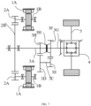
FIG. 7 is a schematic structural view of the drive synthesis box with multi-motors flexible torque according to a fourth embodiment of the present disclosure. - The exemplary embodiments of the present disclosure will be described clearly in the following with reference to the accompanying drawings. Although exemplary embodiments of the present disclosure are shown in the drawings, it should be understood that the present disclosure may be implemented in various forms and should not be limited by the embodiments described herein. Rather, these embodiments are provided for more thorough understanding about the present disclosure, to fully convey the scope claimed in the present disclosure to those skilled in the art.
- At present, in the vehicles with large loads, the motor with a low rotational speed, a large power and a large torque, needs to cooperate with the multi-gear automated mechanical transmission (AMT), thus, the cost of the electric driving system is high. Under most working conditions, the motor rotational speed in the whole vehicle is high, and the whole vehicle cannot keep in the high-efficiency zone all the time or in most cases, which makes the efficiency of the electric driving system low. In the multi-gear (such as 6 gears, 8 gears and 9 gears) AMT, not only the control logic is complex and the gear shift power is prone to be interrupted, but also the motor and the transmission are controlled by different controllers and the integration of components is low. In addition, since a single motor is used for driving, once the motor fails, the vehicle cannot continue driving, and the reliability of the electric driving system is low.
- In order to solve or at least partially solve the above-mentioned technical problems, a drive synthesis box with multi-motors flexible torque is provided in an embodiment of the present disclosure. The technical solutions in the embodiments of the present disclosure will be clearly and completely described in the following with reference to the accompanying drawings of the first embodiment to the fourth embodiment.
- As shown in
FIG. 1 to FIG. 3 , the drive synthesis box with multi-motors flexible torque of this embodiment may at least include apower source 1 and areduction gear assembly 2. Further, the drive synthesis box with multi-motors flexible torque may also include a differential 4. - The number of the
power sources 1 is at least two, and eachpower source 1 includes a drivingmotor 1A for outputting the driving force. The performance and geometric dimensions of each drivingmotor 1A are the same, to simplify the control for the drivingmotor 1A. It should be noted that the number ofpower sources 1 inFIG. 1 to FIG. 3 is only schematic, and can be set according to actual vehicle application requirements. For example, the number ofpower sources 1 can be two, three, or even more. In a specific embodiment, the number ofpower sources 1 may be four. The number ofreduction gear assemblies 2 may be the same as thepower sources 1, and thereduction gear assembly 2 is connected to thepower source 1 in one-to-one correspondence, to transmit the driving force. That is, eachpower source 1 is correspondingly connected to areduction gear assembly 2. The input end of the differential 4 is connected to the output end of eachreduction gear assembly 2, and the output end of the differential 4 is connected to thevehicle axle 5, to transmit the driving force to thevehicle axle 5 and drive the wheels of the vehicle. Thevehicle axle 5 may include a left half shaft and a right half shaft. The left half shaft and the right half shaft, which are used as the driving shafts, are respectively connected to the wheels. The drivingmotor 1A with multiple groups of small torques and a high rotational speed is used to replace the driving motor with a single large torque and a low rotational speed. In this way, not only large torque requirements under a low speed working condition can be met and the power performance of the vehicle at a medium or high speed can be ensured, but also the manufacturing and procurement costs can be reduced. In addition, when acertain driving motor 1A fails, the vehicle can still be driven normally through other drivingmotors 1A, which improves the reliability of the electric driving system. Further, there is no need to set a transmission in this embodiment, which simplifies the control for the drive synthesis box with multi-motors flexible torque, and is especially suitable for vehicles with a low speed use requirements, thereby realizing a highest possible economical efficiency on the premise that the vehicle requirements are met. - As shown in
FIG. 2 , eachpower source 1 includes a drivingmotor 1A and amotor shaft 1B connected to the drivingmotor 1A. Eachreduction gear assembly 2 includes afirst transmission gear 2A connected to themotor shaft 1B and asecond transmission gear 2B meshing with thefirst transmission gear 2A. Thesecond transmission gear 2B is an output end of thereduction gear assembly 2. The drivingmotor 1A is connected to thefirst transmission gear 2A through themotor shaft 1B, then the drivingmotor 1A is connected to the differential 4 through thesecond transmission gear 2B. The driving force output by the drivingmotor 1A is transmitted to the differential 4 by a meshing between thefirst transmission gear 2A and thesecond transmission gear 2B. - The at least two
reduction gear assemblies 2 may share onesecond transmission gear 2B. That is, eachreduction gear assembly 2 includes afirst transmission gear 2A and a sharedsecond transmission gear 2B. In this way, the number of components can be reduced, and the volume of the drive synthesis box with multi-motors flexible torque can be reduced, thereby saving the layout space of the drive synthesis box with multi-motors flexible torque. - Further, in the case that two
reduction gear assemblies 2 shares onesecond transmission gear 2B, the at least twopower sources 1 can be provided along a circumference of thesecond transmission gear 2B. As shown inFIG. 3 ,multiple power sources 1 are distributed along the circumference with thesecond transmission gear 2B as the axis center. In this way, the structure of the drive synthesis box with multi-motors flexible torque is more compact, and the layout space of the drive synthesis box with multi-motors flexible torque can be further saved. - The at least two
power sources 1 are configured to work cooperatively or independently according to the vehicle working condition. In this way, not only the power performance of the vehicle can be met and the drivingmotor 1A can work in the high efficiency zone, but also the power loss of the drivingmotor 1A can be reduced and the efficiency of the electric drive system can be improved. Further, each drivingmotor 1A is configured to operate in different time periods, which makes the accumulated damage of the drivingmotors 1A shared between each drivingmotors 1A, thereby reducing the failure rate of the drivingmotor 1A. - The at least two
power sources 1 are distributed in a forward arrangement. The forward arrangement means that all the drivingmotors 1A are distributed in front of thereduction gear assembly 2. The forward arrangement can simplify the structures of thepower source 1 and thereduction gear assembly 2, and can simplify the assembly between thepower source 1 and thereduction gear assembly 2. Thepower sources 1 can be distributed in other ways, such as a backward arrangement, an opposite arrangement, and the like. - In addition, as shown in
FIG. 1 , the drive synthesis box with multi-motors flexible torque may include at least one dual-motor controller 6 (represented by DMCU inFIG. 1 ), or at least one dual-motor controller 6 and a single-motor controller 7 (represented by MCU inFIG. 1 ). The number of the dual-motor controllers 6 and the single-motor controllers 7 is determined according to the number of the drivingmotors 1A. The dual-motor controller 6 can respectively control the two motors through strategies. In practical applications, dual-motor controllers 6 should be used as much as possible. For example, if the number of drivingmotors 1A is even, all dual-motor controllers 6 may be used, and the number of dual-motor controllers 6 is half of the number of drivingmotors 1A. If the number of drivingmotors 1A is odd, a single-motor controller 7 can be used in addition to the dual motor controller 6. By combining and using an appropriate number of dual-motor controllers 6 and single-motor controllers 7 according to the number of drivingmotors 1A, the manufacturing cost of the motor controller can be reduced. - As shown in
FIG. 4 andFIG. 5 , the difference between the second embodiment and the first embodiment is that the drive synthesis box with multi-motors flexible torque further includes atransmission 3 connecting the input end of the differential 4 with the output end of eachreduction gear assembly 2. In this case, the output end (namely thesecond transmission gear 2B) of eachreduction gear assembly 2 is connected to thetransmission 3, and is further connected to the input end of the differential 4 through thetransmission 3. - The driving
motor 1A, thereduction gear assembly 2, and thetransmission 3 in this embodiment are all built with the inner casing of thetransmission 3 as a carrier, thereby improving the component integration and making the structure of the drive synthesis box with multi-motors flexible torque more compact. - The
transmission 3 includes an input shaft assembly, an intermediate shaft assembly, an output shaft assembly and agear shift device 3H. The input shaft assembly includes aninput shaft 3A connected to thesecond transmission gear 2B and athird transmission gear 3B connected to theinput shaft 3A. Theinput shaft 3A and thethird transmission gear 3B can be integrally formed, or connected to each other through splines. The intermediate shaft assembly includes anintermediate shaft 3C, afourth transmission gear 3D and afifth transmission gear 3E. Both ends of theintermediate shaft 3C are respectively connected to thefourth transmission gear 3D and thefifth transmission gear 3E, and thefourth transmission gear 3D meshes with thethird transmission gear 3B. Thefourth transmission gear 3D is connected to theintermediate shaft 3C through splines, an interference fit and a pressing fit. Thefifth transmission gear 3E is connected to theintermediate shaft 3C through splines, an interference fit and a pressing fit. The output shaft assembly includes anoutput shaft 3G and asixth transmission gear 3F. Theoutput shaft 3G is connected to the input end of the differential 4, and thesixth transmission gear 3F is rotatably installed on theoutput shaft 3G. Thesixth transmission gear 3F meshes with thefifth transmission gear 3E. Thesixth transmission gear 3F is installed on theoutput shaft 3G through a needle bearing, and can rotate along the circumference of theoutput shaft 3G. Thegear shift device 3H is provided on theoutput shaft 3G, and is configured to control the connection between theoutput shaft 3G and thesixth transmission gear 3F or theinput shaft 3A. Thegear shift device 3H can be installed on theoutput shaft 3G through splines or an interference fit. Thegear shift device 3H can include a combination sleeve or a clutch in a dog tooth shape. - Based on the above structure, two gears, namely the first gear and the second gear, can be realized in the
transmission 3. When thetransmission 3 operates in the first gear, thegear shift device 3H is configured to make theoutput shaft 3G connected to thesixth transmission gear 3F, to make the driving force transmitted from thereduction gear assembly 2 sequentially pass through theinput shaft 3A, thethird transmission gear 3B, thefourth transmission gear 3D, theintermediate shaft 3C, thefifth transmission gear 3E, thesixth transmission gear 3F and theoutput shaft 3G to thedifferential 4. When thetransmission 3 operates in the second gear, thegear shift device 3H is configured to make theoutput shaft 3G connected to theinput shaft 3A, to make the driving force transmitted from thereduction gear assembly 2 sequentially pass through theinput shaft 3A and theoutput shaft 3G to the differential 4, to realize a two-gear driving of the vehicle. - In this embodiment, the drive synthesis box with multi-motors flexible torque is provided with a two-gear shift device, which can reduce power interruptions and sudden pauses during gear shifting as much as possible, to improve driving comfort. In addition, compared with the existing multi-gear AMT transmission, the drive synthesis box with multi-motors flexible torque in this embodiment can reduce cost.
- Based on four
power sources 1 and the two-gear transmission 3, the working modes of the drive synthesis box with multi-motors flexible torque will be described clearly in the following. - During the actual running of the vehicle, eight different working modes driven by electricity will occur if four
power sources 1 cooperate with the two-gear transmission 3 for operation. The relationship between each working mode, the gear of thetransmission 3 and thepower source 1 is shown in the table below.working mode number of the driving motor gear of the shift device EV1 1 1 EV2 1 2 EV3 2 1 EV4 2 2 EV5 3 1 EV6 3 2 EV7 4 1 EV8 4 2 - When only one driving
motor 1A is operating and thetransmission 3 is in the first gear state, the working mode is defined as the first gear mode EV1 driven by electricity. The working mode EV1 is suitable for operating under conditions such as a no-load condition, flat roads, downhill roads with a little slope, or cruising at a low speed. In this working mode, power consumption can be saved. In addition, since the vehicle is driven by a single driving motor and other motors do not operate, the mechanical fatigue and damage can be reduced. - When only one driving
motor 1A is operating and thetransmission 3 is in the second gear state, the working mode is defined as the second gear mode EV2 driven by electricity. The working mode EV2 is suitable for operating under conditions such as a no-load condition, flat roads, or cruising at a high speed. - When two driving
motors 1A are operating and thetransmission 3 is in the first gear state, the working mode is defined as the third gear mode EV3 driven by electricity. The working mode EV3 is suitable for operating under conditions such as a no-load condition, starting on flat roads, or driving with light loads and low speeds. - When two driving
motors 1A are operating and thetransmission 3 is in the second gear state, the working mode is defined as the fourth gear mode EV4 driven by electricity. The working mode EV3 is suitable for operating under conditions such as a no-load or a light-load condition, flat roads, or cruising at a high speed. - When three driving
motors 1A are operating and thetransmission 3 is in the first gear state, the working mode is defined as the fifth gear mode EV5 driven by electricity. The working mode EV5 is suitable for operating under conditions such as a medium-load or a standard-load condition, starting, flat roads, or driving with a low speed. - When three driving
motors 1A are operating and thetransmission 3 is in the second gear state, the working mode is defined as the sixth gear mode EV6 driven by electricity. The working mode EV6 is suitable for operating under conditions such as a medium-load or a standard-load condition, flat roads, or driving with a low speed. - When four driving
motors 1A operate simultaneously and thetransmission 3 is in the first gear state, the working mode is defined as the seventh gear mode EV7 driven by electricity. The working mode EV7 is suitable for operating under conditions such as a full-load or an overload condition. Or the working mode EV7 is suitable for the vehicle with a low speed and a large torque to drive on uphill roads with a big slope or start. Under a full-load or an overload condition, the seventh gear mode EV7 can meet requirements of the vehicle with a large torque driving on uphill roads or starting. - When four driving
motors 1A operate simultaneously and thetransmission 3 is in the first gear state, the working mode is defined as the eighth gear mode EV8 driven by electricity. The working mode EV8 is suitable for operating under conditions such as a full-load or an overload condition, starting on flat roads, driving on uphill roads with a little slope, or cruising at a high speed. - In this embodiment, according to the requirements of the vehicle working conditions, multiple groups of driving motors can work cooperatively or independently. Multiple groups of driving motors can cooperate with different gears of the transmission. In this way, not only the vehicle power performance can be met and the driving motors can operate in the high efficiency zone, but also the power loss of the driving motors can be reduced and the efficiency of electric driving systems can be improved.
- As shown in
FIG. 6 , the difference between the third embodiment and the second embodiment is thatmultiple power sources 1 are distributed in an opposite arrangement. The opposite arrangement means that a part of the drivingmotors 1A are distributed in front of thereduction gear assembly 2 and another part of the drivingmotors 1A are distributed in the rear of thereduction gear assembly 2. For example, for twopower sources 1, one of the twopower sources 1 is distributed in front of thereduction gear assembly 2 and the other of the twopower sources 1 is distributed behind thereduction gear assembly 2. In this way, other components or systems of the vehicle can be installed on the idle side in front of thereduction gear assembly 2, to meet the arrangement for the whole vehicle system. - As shown in
FIG. 7 , the difference between the fourth embodiment and the second embodiment is that the plurality ofpower sources 1 are distributed in a backward arrangement. The backward arrangement means that all the drivingmotors 1A are distributed behind thereduction gear assembly 2. In this way, the space along the axial length of the vehicle can be saved, and other components or systems can be installed in the space along the axial direction of the vehicle, to meet the system layout of the whole vehicle. - Based on the same technical concept, an embodiment of the present disclosure also provides an electric vehicle. The electric vehicle includes the drive synthesis box with multi-motors flexible torque described in any embodiment or the combination of embodiments above. The electric vehicle includes, but is not limited to, a pure electric heavy truck, a heavy truck with increased range, a battery replacement heavy truck, and the like.
- Further, an embodiment of the present disclosure further provides a battery replacement heavy truck. The battery replacement heavy truck includes a battery replacement box, and the battery replacement box can be quickly replaced through a battery replacement station.
- According to any one of the above embodiments or a combination of multiple embodiments, the following beneficial effects can be achieved.
- The drive synthesis box with multi-motors flexible torque provided in the embodiment of the present disclosure not only can meet the requirements with a large torque under a low speed condition, but also can ensure the power performance of the vehicle at a medium or high speed. The motor with multiple groups of small torques and a high rotational speed is provided in the drive synthesis box with multi-motors flexible torque, which can reduce manufacturing costs. By using a two-gear shift device, the power interruption can be reduced as much as possible and the driving comfort can be improved. The dual-motor controller may cooperate with the single-motor controller, thereby reducing the manufacturing cost of the motor controller. Further, each driving motor is configured to operate in different time periods, which makes the accumulated damage of the driving motors shared between each driving motors. In addition, when a single driving motor fails, the vehicle can still be driven normally through other driving motors, which improves the reliability of the electric driving system.
- Various specific details are described in the present description. However, it should be understood that embodiments of the present disclosure may be implemented without these specific details. In some embodiments, the well-known methods, structures and technologies are not been shown detailedly in order not to obscure the understanding of the present description.
- It should be noted that the above embodiments are only used to illustrate the technical solutions of the present disclosure, and do not limit the present disclosure. Although the present disclosure has been described in detail with reference to the foregoing embodiments, those skilled in the art should understand that under the inventive concept of the present disclosure, modifications or equivalent transformations can be made according to part or all the technical solutions of the present disclosure, and these modifications or equivalent transformations do not make the corresponding technical solutions deviate from the scope of the present disclosure.
Claims (14)
- A drive synthesis box with multi-motors flexible torque, characterized by comprising:at least two power sources, wherein each of the at least two power sources comprises a driving motor for outputting a driving force; andat least two reduction gear assemblies connected to the at least two power sources in one-to-one correspondence, wherein the two reduction gear assemblies are configured to transmit the driving force.
- The drive synthesis box with multi-motors flexible torque of claim 1, further comprising a differential, wherein an input end of the differential is connected to an output end of each reduction gear assembly, and an output end of the differential is respectively connected to a left driving shaft and a right driving shaft for transmitting the driving force to a wheel end, to drive a wheel of an vehicle.
- The drive synthesis box with multi-motors flexible torque of claim 2, further comprising a transmission connecting the input end of the differential with the output end of each reduction gear assembly.
- The drive synthesis box with multi-motors flexible torque of claim 3, wherein:each power source comprises the driving motor and a motor shaft connected to the driving motor;each reduction gear assembly comprises a first transmission gear connected to the motor shaft and a second transmission gear meshing with the first transmission gear; andthe second transmission gear is an output end of the reduction gear assembly.
- The drive synthesis box with multi-motors flexible torque of claim 4, wherein the at least two reduction gear assemblies share one of second transmission gears.
- The drive synthesis box with multi-motors flexible torque of claim 5, wherein the at least two power sources are provided along a circumference of the second transmission gear.
- The drive synthesis box with multi-motors flexible torque of claim 4, wherein:the transmission comprises an input shaft assembly, an intermediate shaft assembly, an output shaft assembly and a gear shift device,the input shaft assembly comprises an input shaft connected to the second transmission gear and a third transmission gear connected to the input shaft,the intermediate shaft assembly comprises an intermediate shaft, a fourth transmission gear and a fifth transmission gear, both ends of the intermediate shaft are respectively connected to the fourth transmission gear and the fifth transmission gear, and the fourth transmission gear meshes with the third transmission gear,the output shaft assembly comprises an output shaft and a sixth transmission gear, the output shaft is connected to the input end of the differential, the sixth transmission gear is rotatably installed on the output shaft, and the sixth transmission gear meshes with the fifth transmission gear, andthe gear shift device is provided on the output shaft and configured to control a connection between the output shaft and the sixth transmission gear or the input shaft.
- The drive synthesis box with multi-motors flexible torque of claim 7, wherein:when the transmission operates in a first gear, the gear shift device is configured to control the output shaft to connect with the sixth transmission gear, to make the driving force transmitted from the reduction gear assembly sequentially pass through the input shaft, the third transmission gear, the fourth transmission gear, the intermediate shaft, the fifth transmission gear, the sixth transmission gear and the output shaft to the differential; andwhen the transmission operates in a second gear, the gear shift device is configured to control the output shaft to connect with the input shaft, to make the driving force transmitted from the reduction gear assembly sequentially pass through the input shaft and the output shaft to the differential, to realize a two-gear driving of the vehicle.
- The drive synthesis box with multi-motors flexible torque of claim 1, wherein the at least two power sources are configured to work cooperatively or independently in a controlled manner.
- The drive synthesis box with multi-motors flexible torque of claim 1, wherein the at least two power sources are distributed in one of following manners:
a forward arrangement, a backward arrangement and an opposite arrangement. - The drive synthesis box with multi-motors flexible torque of claim 1, further comprising at least one dual-motor controller, or at least one dual-motor controller and a single-motor controller, wherein a number of the dual-motor controller and the single-motor controllers is determined according to a number of the driving motors.
- An electric vehicle, characterized by comprising the drive synthesis box with multi-motors flexible torque of any one of claims 1-11.
- The electric vehicle of claim 12, wherein the electric vehicle comprises a pure electric heavy truck, a heavy truck with increased range, and a battery replacement heavy truck.
- The electric vehicle of claim 13, wherein the battery replacement heavy truck comprises a battery replacement box, and the battery replacement box is quickly replaced through a battery replacement station.
Applications Claiming Priority (2)
| Application Number | Priority Date | Filing Date | Title |
|---|---|---|---|
| CN202011246947.2A CN112356647B (en) | 2020-11-10 | 2020-11-10 | Multi-motor flexible torque centralized driving synthesis box and electric vehicle |
| PCT/CN2020/138038 WO2022099865A1 (en) | 2020-11-10 | 2020-12-21 | Multi-motor flexible torque centralized driving synthesis box and electric vehicle |
Publications (2)
| Publication Number | Publication Date |
|---|---|
| EP4230453A1 true EP4230453A1 (en) | 2023-08-23 |
| EP4230453A4 EP4230453A4 (en) | 2024-10-09 |
Family
ID=74508621
Family Applications (1)
| Application Number | Title | Priority Date | Filing Date |
|---|---|---|---|
| EP20961418.9A Pending EP4230453A4 (en) | 2020-11-10 | 2020-12-21 | FLEXIBLE MULTI-ENGINE SYNTHESIS BOX WITH CENTRAL TORQUE AND ELECTRIC VEHICLE |
Country Status (6)
| Country | Link |
|---|---|
| US (1) | US12539749B2 (en) |
| EP (1) | EP4230453A4 (en) |
| JP (1) | JP7592182B2 (en) |
| KR (1) | KR20230121733A (en) |
| CN (1) | CN112356647B (en) |
| WO (1) | WO2022099865A1 (en) |
Families Citing this family (10)
| Publication number | Priority date | Publication date | Assignee | Title |
|---|---|---|---|---|
| CN113027998B (en) * | 2021-02-25 | 2022-08-19 | 凯博易控车辆科技(苏州)股份有限公司 | Variable-speed driving system with multiple driving motors and gear shifting control method thereof |
| GB202109409D0 (en) | 2021-06-30 | 2021-08-11 | Mclaren Automotive Ltd | Drive system for a vehicle |
| CN113682119B (en) * | 2021-09-05 | 2023-03-28 | 凯博易控车辆科技(苏州)股份有限公司 | Dual-motor speed change system |
| CN113580928A (en) * | 2021-09-07 | 2021-11-02 | 南昌智能新能源汽车研究院 | Double-motor series connection two-pole speed reducer and control method thereof |
| FR3131711A1 (en) * | 2022-01-08 | 2023-07-14 | Valeo Embrayages | PROPULSION SYSTEM FOR ELECTRIC VEHICLES |
| CN114811036B (en) * | 2022-05-25 | 2023-07-25 | 银川威力传动技术股份有限公司 | Multi-mode double-motor two-gear gearbox for electric automobile |
| CN114987178A (en) * | 2022-06-23 | 2022-09-02 | 银川威力传动技术股份有限公司 | Transmission assembly of double-motor speed reducer |
| CN115848161B (en) * | 2022-12-06 | 2024-12-13 | 中国重汽集团济南动力有限公司 | A dual-axle driven electric drive axle vehicle and a multi-motor control system, method and vehicle |
| CN118061760A (en) * | 2024-03-29 | 2024-05-24 | 重庆长安汽车股份有限公司 | Distributed electric drive system and electric vehicle |
| CN119840425B (en) * | 2025-03-21 | 2025-06-06 | 江铃汽车股份有限公司 | Limp control method and system for single motor faults of electric four-wheel drive vehicle type |
Family Cites Families (31)
| Publication number | Priority date | Publication date | Assignee | Title |
|---|---|---|---|---|
| JP4274268B2 (en) * | 2007-06-19 | 2009-06-03 | トヨタ自動車株式会社 | Power transmission device |
| KR20090063461A (en) * | 2007-12-14 | 2009-06-18 | 성 훈 김 | Multi-motor device with high fault stability and high control accuracy |
| CN201777126U (en) * | 2010-05-31 | 2011-03-30 | 比亚迪股份有限公司 | Hybird power drive system and vehicle comprising same |
| JP5734287B2 (en) * | 2010-06-01 | 2015-06-17 | 株式会社日立ニコトランスミッション | Twin clutch transmission |
| ES2373905B1 (en) | 2011-11-25 | 2012-09-07 | Urban Resilience, S.L. | Installation for parking and recharging of electric vehicles. |
| DE102011056046B4 (en) | 2011-12-05 | 2022-05-25 | Dr.Ing.H.C.F.Porsche Aktiengesellschaft | Drive train of a purely electric all-wheel drive motor vehicle |
| DE102011056048B4 (en) | 2011-12-05 | 2025-03-27 | Dr. Ing. H.C. F. Porsche Aktiengesellschaft | Drivetrain of a purely electric all-wheel drive vehicle |
| DE102013204227A1 (en) * | 2013-03-12 | 2014-09-18 | Zf Friedrichshafen Ag | Drive train for a vehicle and method for performing a load change |
| JPWO2014141569A1 (en) * | 2013-03-13 | 2017-02-16 | 日産自動車株式会社 | Control device for automatic transmission |
| US10844935B2 (en) * | 2014-07-18 | 2020-11-24 | Uvic Industry Partnerships Inc. | Electric drive system with a novel dual-clutch transmission |
| KR101755818B1 (en) * | 2015-08-07 | 2017-07-20 | 현대자동차주식회사 | Transmission for electric vehicle |
| JP2017206074A (en) | 2016-05-17 | 2017-11-24 | Ntn株式会社 | Two-motor vehicle drive device for four-wheel drive vehicle |
| CN106080155B (en) * | 2016-06-28 | 2019-11-05 | 台州市皓仔邦工业设计有限公司 | A kind of optimization integrated system and shift control method of driving motor and automatic transmission |
| CN206336116U (en) | 2016-10-10 | 2017-07-18 | 蔚来汽车有限公司 | Electric vehicle power coupling system and electric vehicle with same |
| CN108340760A (en) * | 2017-01-19 | 2018-07-31 | 台州双擎动力科技有限公司 | A kind of pure electric vehicle power assembly system |
| DE102017205662A1 (en) * | 2017-04-04 | 2018-10-04 | Zf Friedrichshafen Ag | Powertrain for a vehicle |
| CN207173300U (en) * | 2017-09-14 | 2018-04-03 | 韶能集团韶关宏大齿轮有限公司 | Bi-motor inputs two-gear automatic speed changing transmission system |
| KR20190068961A (en) * | 2017-12-11 | 2019-06-19 | 현대자동차주식회사 | Device for torque vectoring |
| CN108297736A (en) * | 2017-12-27 | 2018-07-20 | 安徽融智天骏新能源汽车有限公司 | A kind of bi-motor distributed-driving electric automobile and motor control strategy |
| CN208134053U (en) * | 2017-12-29 | 2018-11-23 | 聊城大学 | A kind of pure electric automobile bi-motor coupler |
| CN110126604B (en) * | 2018-02-08 | 2024-06-14 | 宇通客车股份有限公司 | Pure electric motor drive system and electric vehicle |
| CN108528185B (en) * | 2018-06-07 | 2024-01-19 | 精进电动科技股份有限公司 | Longitudinally-arranged multi-gear electric driving power assembly |
| CN109263454B (en) * | 2018-10-23 | 2021-05-28 | 南京越博动力系统股份有限公司 | A shift control method for a dual-motor transverse electric drive axle assembly system |
| CN111114268A (en) * | 2018-10-30 | 2020-05-08 | 郑州宇通客车股份有限公司 | Two keep off electricelectric moves sanitation car driving system and electricelectric moves sanitation car |
| CN209320658U (en) * | 2018-10-30 | 2019-08-30 | 郑州宇通客车股份有限公司 | Two gear pure electric vehicle sanitation cart dynamical systems and pure electric vehicle sanitation cart |
| CN109519505A (en) * | 2018-12-27 | 2019-03-26 | 凯博易控驱动(苏州)股份有限公司 | Bi-motor two keeps off power drive system, control method and electric car |
| CN109649147A (en) * | 2019-01-31 | 2019-04-19 | 郑州智驱科技有限公司 | A kind of pure electric vehicle bi-motor input parallel axes two speed transmission transmission scheme |
| CN109854700B (en) * | 2019-03-15 | 2024-04-05 | 重庆青山工业有限责任公司 | Transmission assembly, gear shifting power compensation method and pure electric vehicle |
| CN210652645U (en) * | 2019-06-27 | 2020-06-02 | 郑州宇通客车股份有限公司 | Pure electric vehicle and electric drive power system thereof |
| CN211335435U (en) * | 2019-09-17 | 2020-08-25 | 东风德纳车桥有限公司 | Double-motor integrated two-gear AMT double-speed parallel shaft secondary belt wheel side speed reduction electric drive axle |
| CN112477570B (en) * | 2020-12-15 | 2022-11-29 | 浙江吉利控股集团有限公司 | Drive synthesis device and electric vehicle |
-
2020
- 2020-11-10 CN CN202011246947.2A patent/CN112356647B/en active Active
- 2020-12-21 KR KR1020237018311A patent/KR20230121733A/en not_active Ceased
- 2020-12-21 EP EP20961418.9A patent/EP4230453A4/en active Pending
- 2020-12-21 JP JP2023550338A patent/JP7592182B2/en active Active
- 2020-12-21 WO PCT/CN2020/138038 patent/WO2022099865A1/en not_active Ceased
-
2023
- 2023-05-10 US US18/315,015 patent/US12539749B2/en active Active
Also Published As
| Publication number | Publication date |
|---|---|
| US20230278409A1 (en) | 2023-09-07 |
| JP2023548245A (en) | 2023-11-15 |
| CN112356647B (en) | 2022-04-08 |
| JP7592182B2 (en) | 2024-11-29 |
| CN112356647A (en) | 2021-02-12 |
| US12539749B2 (en) | 2026-02-03 |
| EP4230453A4 (en) | 2024-10-09 |
| WO2022099865A1 (en) | 2022-05-19 |
| KR20230121733A (en) | 2023-08-21 |
Similar Documents
| Publication | Publication Date | Title |
|---|---|---|
| US12539749B2 (en) | Drive synthesis box with multi-motors flexible torque and electric vehicle | |
| US12491790B2 (en) | Battery replacement vehicle without intermediate transmission shaft | |
| CN113635709B (en) | Multi-mode torque-directed electric transaxle with single actuator | |
| CN210970550U (en) | Double-motor electric drive axle assembly with wheel-side speed reducer | |
| CN117565651A (en) | Electric axles and electric trucks | |
| CN210652645U (en) | Pure electric vehicle and electric drive power system thereof | |
| CN112477571A (en) | Multi-motor driving device and electric vehicle | |
| CN215321961U (en) | A vehicle with a dual-motor electric drive axle | |
| CN112477570B (en) | Drive synthesis device and electric vehicle | |
| CN218287331U (en) | Double-motor single-gear electric drive axle | |
| CN114393982B (en) | Dual-motor electric drive axle | |
| CN220785437U (en) | Double-planet row mixing system | |
| CN219769544U (en) | Coaxial double-motor two-gear electric drive axle based on synchronizer control | |
| US12030377B2 (en) | Electric powertrain for a vehicle | |
| WO2025015738A1 (en) | Two-gear driving assembly and new energy vehicle | |
| CN215850710U (en) | Coaxial integrated double-motor double-speed-ratio electric drive assembly and electric vehicle | |
| CN112128323B (en) | Two-gear reduction gearbox with Simpson type planetary gear structure and power transmission logic | |
| CN213799264U (en) | Transmission mechanism and driving system for motor vehicle | |
| RU2818058C2 (en) | Flexible torque multi-engine drive box and electric vehicle | |
| CN214001302U (en) | Multi-gear multi-motor flexible torque centralized driving synthesis box and electric vehicle | |
| CN223825540U (en) | A planetary gear train type reduction differential transmission mechanism | |
| CN223494276U (en) | A dual-motor electric drive system for pure electric vehicles | |
| CN217294237U (en) | Hybrid power driving system and automobile | |
| CN222522450U (en) | Dual-motor two-gear electronic differential drive axle | |
| CN220562527U (en) | Double-motor coaxial electric drive axle |
Legal Events
| Date | Code | Title | Description |
|---|---|---|---|
| STAA | Information on the status of an ep patent application or granted ep patent |
Free format text: STATUS: THE INTERNATIONAL PUBLICATION HAS BEEN MADE |
|
| PUAI | Public reference made under article 153(3) epc to a published international application that has entered the european phase |
Free format text: ORIGINAL CODE: 0009012 |
|
| STAA | Information on the status of an ep patent application or granted ep patent |
Free format text: STATUS: REQUEST FOR EXAMINATION WAS MADE |
|
| 17P | Request for examination filed |
Effective date: 20230515 |
|
| AK | Designated contracting states |
Kind code of ref document: A1 Designated state(s): AL AT BE BG CH CY CZ DE DK EE ES FI FR GB GR HR HU IE IS IT LI LT LU LV MC MK MT NL NO PL PT RO RS SE SI SK SM TR |
|
| DAV | Request for validation of the european patent (deleted) | ||
| DAX | Request for extension of the european patent (deleted) | ||
| A4 | Supplementary search report drawn up and despatched |
Effective date: 20240905 |
|
| RIC1 | Information provided on ipc code assigned before grant |
Ipc: F16H 1/22 20060101ALN20240830BHEP Ipc: F16H 3/089 20060101ALN20240830BHEP Ipc: B60L 15/20 20060101ALI20240830BHEP Ipc: B60L 3/00 20190101ALI20240830BHEP Ipc: B60K 1/02 20060101AFI20240830BHEP |