EP4230423A1 - Method and user interface for double-sided printing on a printing system - Google Patents
Method and user interface for double-sided printing on a printing system Download PDFInfo
- Publication number
- EP4230423A1 EP4230423A1 EP22156979.1A EP22156979A EP4230423A1 EP 4230423 A1 EP4230423 A1 EP 4230423A1 EP 22156979 A EP22156979 A EP 22156979A EP 4230423 A1 EP4230423 A1 EP 4230423A1
- Authority
- EP
- European Patent Office
- Prior art keywords
- recording medium
- side image
- back side
- printing system
- printing
- Prior art date
- Legal status (The legal status is an assumption and is not a legal conclusion. Google has not performed a legal analysis and makes no representation as to the accuracy of the status listed.)
- Granted
Links
Images



Classifications
-
- B—PERFORMING OPERATIONS; TRANSPORTING
- B41—PRINTING; LINING MACHINES; TYPEWRITERS; STAMPS
- B41J—TYPEWRITERS; SELECTIVE PRINTING MECHANISMS, i.e. MECHANISMS PRINTING OTHERWISE THAN FROM A FORME; CORRECTION OF TYPOGRAPHICAL ERRORS
- B41J3/00—Typewriters or selective printing or marking mechanisms characterised by the purpose for which they are constructed
- B41J3/60—Typewriters or selective printing or marking mechanisms characterised by the purpose for which they are constructed for printing on both faces of the printing material
-
- B—PERFORMING OPERATIONS; TRANSPORTING
- B41—PRINTING; LINING MACHINES; TYPEWRITERS; STAMPS
- B41J—TYPEWRITERS; SELECTIVE PRINTING MECHANISMS, i.e. MECHANISMS PRINTING OTHERWISE THAN FROM A FORME; CORRECTION OF TYPOGRAPHICAL ERRORS
- B41J11/00—Devices or arrangements of selective printing mechanisms, e.g. ink-jet printers or thermal printers, for supporting or handling copy material in sheet or web form
- B41J11/66—Applications of cutting devices
- B41J11/663—Controlling cutting, cutting resulting in special shapes of the cutting line, e.g. controlling cutting positions, e.g. for cutting in the immediate vicinity of a printed image
-
- G—PHYSICS
- G06—COMPUTING OR CALCULATING; COUNTING
- G06F—ELECTRIC DIGITAL DATA PROCESSING
- G06F3/00—Input arrangements for transferring data to be processed into a form capable of being handled by the computer; Output arrangements for transferring data from processing unit to output unit, e.g. interface arrangements
- G06F3/12—Digital output to print unit, e.g. line printer, chain printer
- G06F3/1201—Dedicated interfaces to print systems
- G06F3/1202—Dedicated interfaces to print systems specifically adapted to achieve a particular effect
- G06F3/1203—Improving or facilitating administration, e.g. print management
- G06F3/1208—Improving or facilitating administration, e.g. print management resulting in improved quality of the output result, e.g. print layout, colours, workflows, print preview
-
- G—PHYSICS
- G06—COMPUTING OR CALCULATING; COUNTING
- G06F—ELECTRIC DIGITAL DATA PROCESSING
- G06F3/00—Input arrangements for transferring data to be processed into a form capable of being handled by the computer; Output arrangements for transferring data from processing unit to output unit, e.g. interface arrangements
- G06F3/12—Digital output to print unit, e.g. line printer, chain printer
- G06F3/1201—Dedicated interfaces to print systems
- G06F3/1223—Dedicated interfaces to print systems specifically adapted to use a particular technique
- G06F3/1237—Print job management
- G06F3/1242—Image or content composition onto a page
-
- G—PHYSICS
- G06—COMPUTING OR CALCULATING; COUNTING
- G06F—ELECTRIC DIGITAL DATA PROCESSING
- G06F3/00—Input arrangements for transferring data to be processed into a form capable of being handled by the computer; Output arrangements for transferring data from processing unit to output unit, e.g. interface arrangements
- G06F3/12—Digital output to print unit, e.g. line printer, chain printer
- G06F3/1201—Dedicated interfaces to print systems
- G06F3/1223—Dedicated interfaces to print systems specifically adapted to use a particular technique
- G06F3/1237—Print job management
- G06F3/125—Page layout or assigning input pages onto output media, e.g. imposition
- G06F3/1251—Page layout or assigning input pages onto output media, e.g. imposition for continuous media, e.g. web media, rolls
-
- G—PHYSICS
- G06—COMPUTING OR CALCULATING; COUNTING
- G06F—ELECTRIC DIGITAL DATA PROCESSING
- G06F3/00—Input arrangements for transferring data to be processed into a form capable of being handled by the computer; Output arrangements for transferring data from processing unit to output unit, e.g. interface arrangements
- G06F3/12—Digital output to print unit, e.g. line printer, chain printer
- G06F3/1201—Dedicated interfaces to print systems
- G06F3/1278—Dedicated interfaces to print systems specifically adapted to adopt a particular infrastructure
- G06F3/1282—High volume printer device
-
- B—PERFORMING OPERATIONS; TRANSPORTING
- B41—PRINTING; LINING MACHINES; TYPEWRITERS; STAMPS
- B41J—TYPEWRITERS; SELECTIVE PRINTING MECHANISMS, i.e. MECHANISMS PRINTING OTHERWISE THAN FROM A FORME; CORRECTION OF TYPOGRAPHICAL ERRORS
- B41J11/00—Devices or arrangements of selective printing mechanisms, e.g. ink-jet printers or thermal printers, for supporting or handling copy material in sheet or web form
- B41J11/0065—Means for printing without leaving a margin on at least one edge of the copy material, e.g. edge-to-edge printing
-
- B—PERFORMING OPERATIONS; TRANSPORTING
- B41—PRINTING; LINING MACHINES; TYPEWRITERS; STAMPS
- B41J—TYPEWRITERS; SELECTIVE PRINTING MECHANISMS, i.e. MECHANISMS PRINTING OTHERWISE THAN FROM A FORME; CORRECTION OF TYPOGRAPHICAL ERRORS
- B41J15/00—Devices or arrangements of selective printing mechanisms, e.g. ink-jet printers or thermal printers, specially adapted for supporting or handling copy material in continuous form, e.g. webs
- B41J15/04—Supporting, feeding, or guiding devices; Mountings for web rolls or spindles
Definitions
- the invention relates to a method for double-sided printing of a plurality of digital images on a recording medium by means of a printing system, each image of the plurality of digital images consisting of a plurality of pixels, wherein the method comprises the steps of
- the printing system may be a cut sheet printing system or a roll-based printing system.
- the cut sheet printing system may be a flatbed printer.
- the roll based printing system may be a roll to roll printing system or a roll to sheet printing system.
- the roll to roll printing system may also be called “roll to roll printer”, “R2R printing system” or “R2R printer”.
- the roll to sheet printing system may also be called “roll to sheet printer”, “R2S printing system” or “R2S printer”.
- the cut sheet printing system may also be called “cut sheet printer”, “CS printing system” or “CS printer”.
- a personal workstation of a user and the printing system are interconnected for printing digital images that have been made in a workstation.
- Digital image reproduction apparatuses can advantageously be used as printing systems for printing on a sheet or roll of recording medium.
- a digital image apparatus includes a scanner unit, a print unit, a memory, and a user interface integrated in the apparatus or remotely usable by an operator.
- the user interface is provided with an input capability and a display that permit a user to give operator control commands to the apparatus.
- the printing system includes a network connection unit for coupling to a network for the purpose of communication with a digital external environment having at least a number of workstations of users, and a print controller connected to the scanner unit, printing system unit, memory and network connection unit, and, via the network connection unit, to the workstations and even to other printing systems in the network.
- the method according to the present invention is used for double sided printing, i.e. printing on both sides of the recording medium.
- a sheet or roll is firstly printed on one side of the recording medium and secondly on the other side of the recording medium.
- the one side of the recording medium is referred to as a front side
- the other side of the recording medium is referred to as a back side.
- printers which are configured to print both front and back side of a sheet or roll substantially simultaneously.
- the front side image to be printed and the corresponding back side image to be printed may be received by the print controller in the form of one print job containing both images.
- a print job may also contain a plurality of front side images and a plurality of corresponding back side images.
- the present invention generally pertains to a method for controlling a printing system for printing images on a recording medium, the printing system comprising a print engine and a controller.
- the invention also pertains to a software medium comprising executable code configured to, when executed, perform a method for controlling a printing system.
- the invention also pertains to a printing system configured to execute the method according to the invention.
- marking is used herein as a general term for any marking of a recording medium with any marking material.
- image forming may be used.
- Recording mediums may comprise paper, flexible plastic, metal foils, textiles and so on.
- Marking materials may comprise ink, metal, varnish, toner and so on.
- Marking may be any process by which the marking material is applied to the recording medium.
- a recording medium is transported from an input holder along a paper path comprising a marking unit to an output holder.
- a recording medium such as paper is wound up on an input roll and then fed into, and guided along, a path through the printer, unwinding the input roll by and by along the process.
- the recording medium is fed to a marking unit of the printer which applies a marking material (prints) onto the recording medium.
- Roll-to-roll printers are a common type of roll-fed printers and are characterized in that the recording medium is, after images have been printed on it, wound up on an output holder of an output roll by and by along the process.
- Some printers comprise a cutting unit configured to cut the recording medium after images have been printed on it such that the printer does not output the entire contiguous recording medium but instead cut pieces of it.
- a cutting unit configured to cut the recording medium after images have been printed on it such that the printer does not output the entire contiguous recording medium but instead cut pieces of it.
- An example of such a printer is a R2S printer.
- Rigids or large sheets may be printed on both sides by means of a flatbed printer and cut afterwards by a cutter.
- the method of the invention is also applicable to flatbed printing production.
- Roll-fed printers are very efficient devices for forming a large number of images requiring a large amount of the recording medium, as the wound-up input rolls are comparatively easy to handle by both the printers and their operating personnel. Accordingly, little or no supervision by personnel is needed for roll-fed printers, especially for roll-to-roll printers, as the marked recording medium is automatically stored on the output roll.
- a cutting machine may be installed next to the printer for cutting the printed front side image out of the recording medium after printing the front side image on the recording medium.
- the cutting machine is able to read the cut marks provided to the front side image in order to establish an accurate cutting process.
- a plurality of individual digital images are received by the print controller and are arranged in such a way that a front side image and a back side image are scheduled to be printed on the first location of the front side of the recording medium and on the second location of the back side of the recording medium respectively.
- the first location and the second location have the same X, Y coordinates with respect to common coordinate system.
- the fact that the creation and fill out of the additional pixels is automated is in particular advantageous when a large amount of images is to be printed on the recording medium. For example, when a complete roll is intended to be double-sided printed, each back side image intended to be printed on the back side of the roll is automatically provided with the additional pixels.
- the automation according to the invention is also advantageous, when a large set of images is intended to be double-sided printed on a large plurality of cut sheets.
- the printing system comprises a user interface which is configured to display a plurality of front side images and a plurality of selectable back side images corresponding to the front side images and the method comprises the steps of selecting at least one selectable back side image and applying the steps of the method according to the invention to the at least one selected back side image.
- the printing system has a system setting that automatically selects each back side image in case of double-sided printing of the back side image and the corresponding front side image.
- the step of establishing the fill out of the additional pixels comprises a fill out of an area between a bleed box and a trim box of the back side image, wherein the bleed box is surrounding the trim box and the trim box has the same dimensions as the back side image.
- the step of establishing the fill out comprises the sub-step of replicating all pixels on all edges of the back side image into the additional pixels.
- the present invention also relates to a printing system for double-sided printing of a plurality of digital images on a recording medium, the printing system configured to execute a method according to the invention.
- the printing system is a roll-based printing system and the recording medium is a roll of medium.
- the roll-based printing system is a roll to roll printing system.
- the printing system is a flatbed printer.
- the present invention also relates to a software medium comprising executable program code to cause a print controller of the printing system according to the invention to execute the steps of a method according to the invention.
- FIG. 1 shows three printers 1A, 1B, 1C which are connected to a network N.
- the printers 1a, 1B, 1C are configured to execute the steps of the method according to the present invention.
- FIG. 1 shows schematically a printing system 1A which comprises at least one input holder 2A, 3A for holding a recording medium which is intended to be used for printing of print jobs from the print job queue of the printing system 1A by means of the marking unit (not shown).
- the marking unit may comprise at least one print head for adhering marking material like ink or toner to the recording medium.
- the recording medium in the least one input holder 2A, 3A is transported to a marking unit of the printing system 1A.
- the printing system 1A also comprises a local user interface 5A.
- a specific printing system is shown and described, the disclosed embodiments may be used with other types of a printing system such as an inkjet printing system, an electrographic printing system, a cut sheet printing system, a roll fed printing system, a flatbed printing system, etc.
- the printing system 1B also comprises a local user interface 5B, and at least one input holder 2B, 3B.
- the printing system 1C comprises an input roll holder for holding an input roll 3C of recording medium, a user interface 5C and a print controller 4C for controlling the printing process on the input roll 3C and maintaining a print job queue residing in the print controller 4C.
- the printing systems 1A, 1B, 1C are digitally connected to a network N for bi-directional data signal transfer.
- the printing systems 1A, 1B, 1C comprise a print controller 4A, 4B, 4C respectively for controlling the printing process.
- the print controller 4A, 4B, 4C is a computer or server or a workstation, connected to the print engine of the printing system 1A, 1B, 1C respectively and connected to the digital environment of the printing system, for example the network N for transmitting a submitted print job to the printing system.
- a print engine of the printing system 1A, 1B, 1C comprises a print head or print assembly for ejecting and/or fixing marking material to the recording medium and a paper path for transporting the recording medium from the input holders 2A, 2B, 3A, 3B, 3C to the print head or print assembly.
- the print head or print assembly may be an inkjet print head, a direct imaging toner assembly or an indirect imaging toner assembly. While a recording medium is transported along the paper path, the recording medium receives the marking material from the print head or print assembly before the printed recording medium is output in an output holder.
- An operator 12 present in the neighbourhood of the printing systems 1A, 1B, 1C or even in another building than the printing systems 1A, 1B, 1C may use a remote wireless user interface 13 displaying printer processing information 14 of the printers 1A, 1B, 1C.
- the local user interfaces 5A, 5B, 5C and the remote user interface 13 are suitable for displaying user interface windows for controlling the print job queue residing in the print controller 4A, 4B, 4C respectively.
- the local user interfaces 5A, 5B, 5C and the wireless remote user interfaces 13 are suitable for displaying images - front and back side images - to be printed according to the invention, e.g.
- a front side image with cut marks, a back side image with trim box and filled-out bleed box according to the method of the present invention.
- the user interface window comprises a user operable item (not shown) for selecting at least one back side image to which the method according to the invention is applied.
- a computer in the network N has a wired (or even wireless) remote user interface for displaying the front and back side images according to the invention and controlling the print job queue of the printing systems 1A, 1B, 1C like the work stations 11A, 11B, 11C in FIG. 1 .
- the print controller 4A, 4B, 4C comprises a memory comprising received images to be printed.
- the print controller 4A, 4B, 4C is configured to receive the images to be printed double-sided on the recording medium and to apply electronic signals to the user interface 5A, 5B, 5C, 13 based on the received images to show the received images in an appropriate user interface window.
- the print controller 4A, 4B, 4C is also configured - in case of double-sided printing - to couple a front side image to a back side image which have to be printed at a same X,Y location at the front side, respectively back side of the recording medium. The coupling may take place via user input by means of the user interface 5A, 5B, 5C, 13.
- Fig. 2 shows a schematic view of a front side image 23, a back side image 24 and an extended back side image 2A according to the invention.
- the front side image 23 is intended to be printed on a front side 21 of the recording medium.
- the extended back side image 2A including the original back side image 24 and additional pixels 28 is intended to be printed on a back side 22 of the recording medium.
- the recording medium shown in Fig. 2 can have arbitrary dimensions in an X and Y direction.
- the front side image 23 is printed with cut marks 25 for cutting the printed front side image out of the recording medium after printing the front side image 23 and the extended back side image 2A.
- the front side image 23 consists of pixels (not shown) which have values with respect to an XY position and a colour.
- the back side image 24 consists of pixels 26 which have values with respect to an XY position and a colour.
- the back side image 24 is automatically extended with additional coloured pixels 28 shown with an asterix (*) in Fig. 2 .
- the additional coloured pixels 28 are surrounding the back side image 24 on all edges of the back side image 24.
- the rows and columns of additional pixels 28 shown in Fig. 2 have a width of one pixel.
- rows and columns having a width of more than one pixel may be envisioned.
- a system setting for double-sided printing may be provided by the printing system which system setting defines a default value for the width of the rows and columns of the additional pixels 28.
- the user interface of the printing system is providing a corresponding print setting for the same purpose in order to set another value for the width than the default value.
- the width may be expressed in a SI unit like mm. or in a number of pixels.
- a colour of an additional pixel is determined to be equal to a colour of corresponding pixel on an edge of the back side image 24.
- an additional pixel 20 gets a blue colour (indicated with character "B" in Fig. 2 ) which equals the colour of the corresponding pixel 27 on an edge of the back side image 24.
- an additional pixel 2B gets a red colour (indicated with character "R” in Fig. 2 ) which equals the colour of the corresponding pixel 29 on an edge of the back side image 24.
- Fig. 3 shows a back side of a virtual recording medium 30 provided with a back side image 32 with a trim box 32.
- a trim box 32 Within the trim box 32 there is an art box 31. Outside of the trim box 32 there is a bleed box 33 and a media box 34.
- the virtual recording medium 30 is also provided with cut marks 35 which are present on the front side (not shown) of the virtual recording medium 30. The cut marks 35 aligned with the edges of the trim box 32 and the edges of the image 32.
- the automatic fill out of the additional pixels 28 shown in Fig. 2 comprises a fill out of an area between the bleed box 33 and the trim box 32 of the back side image 32, wherein the bleed box 33 is surrounding the trim box 32 and the trim box 32 has the same dimensions as the back side image 32.
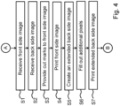
- Fig. 4 shows a schematic flow diagram illustrating a method according to the invention.
- the method is suitable for controlling a printing system for printing images on both sides of the recording medium.
- the printing system comprises a print engine and a print controller for managing the printing of digital images on both sides of the recording medium.
- the method starts in a starting point A and leads to a first step S1.
- the print controller receives a front side image to be printed at a first location on a first side of the recording medium.
- a second step S2 the print controller receives a back side image to be printed at a second location on a second side of the sheet corresponding to the location on the first side of the recording medium.
- a third step S3 the front side image is provided with cut marks for a cutting process applied to the front side image, wherein the cutting process is planned after printing on both sides of the recording medium.
- a fourth step S4 the front side image and the cut marks are printed at the first location on the first side of the recording medium.
- a fifth step S5 an extended back side image is automatically created which comprises the back side image and additional pixels surrounding the back side image.
- a fill out of the additional pixels by coloured pixels is automatically established.
- a seventh step S7 the extended back side image is printed at the second side of the recording medium such that the back side image is printed at the second location on the second side of the recording medium.
- the first step S1 and the second step S2 may be interchanged.
- the fourth step S4 may be executed just before the seventh step S7.
- the method ends in an end point B.
- Fig. 5 schematically shows a non-transitory software medium 50 according to the invention.
- the software medium 50 comprises executable code 52 configured to, when executed, perform the method according to the invention, e.g. as described with respect to either the printing system 1A, 1B, 1C shown in Fig. 1 or the method of controlling the printing system 1A, 1B, 1C according to any or all of the Figs. 1 to 4 and/or according to any of the variants and modifications of the printing system 1A, 1B, 1C and/or of the method described herein.
- the non-transitory software medium 50 may, specifically, be formed as a CD or a CD-ROM, a DVD or a DVD-ROM, a BluRay disc or a BluRay-ROM disc, a magnetic hard drive, a solid state disk (SSD) hard drive, a USB memory device and so on.
Landscapes
- Engineering & Computer Science (AREA)
- Theoretical Computer Science (AREA)
- Human Computer Interaction (AREA)
- Physics & Mathematics (AREA)
- General Engineering & Computer Science (AREA)
- General Physics & Mathematics (AREA)
- Quality & Reliability (AREA)
- Dot-Matrix Printers And Others (AREA)
Abstract
Description
- The invention relates to a method for double-sided printing of a plurality of digital images on a recording medium by means of a printing system, each image of the plurality of digital images consisting of a plurality of pixels, wherein the method comprises the steps of
- receiving a front side image to be printed at a first location on a first side of the recording medium,
- receiving a back side image to be printed at a second location on a second side of the recording medium corresponding to the location on the first side of the recording medium,
- providing the front side image with cut marks for a cutting process applied to the front side image, wherein the cutting process is planned after printing on both sides of the recording medium, and
- printing the front side image and the cut marks at the first location on the first side of the recording medium.
- The printing system may be a cut sheet printing system or a roll-based printing system.
- The cut sheet printing system may be a flatbed printer.
- The roll based printing system may be a roll to roll printing system or a roll to sheet printing system. Hereinafter the roll to roll printing system may also be called "roll to roll printer", "R2R printing system" or "R2R printer". Hereinafter the roll to sheet printing system may also be called "roll to sheet printer", "R2S printing system" or "R2S printer". Hereinafter the cut sheet printing system may also be called "cut sheet printer", "CS printing system" or "CS printer".
- For instance, in a network system, a personal workstation of a user and the printing system are interconnected for printing digital images that have been made in a workstation. Digital image reproduction apparatuses can advantageously be used as printing systems for printing on a sheet or roll of recording medium. Such a digital image apparatus includes a scanner unit, a print unit, a memory, and a user interface integrated in the apparatus or remotely usable by an operator. The user interface is provided with an input capability and a display that permit a user to give operator control commands to the apparatus. Further, the printing system includes a network connection unit for coupling to a network for the purpose of communication with a digital external environment having at least a number of workstations of users, and a print controller connected to the scanner unit, printing system unit, memory and network connection unit, and, via the network connection unit, to the workstations and even to other printing systems in the network.
- The method according to the present invention is used for double sided printing, i.e. printing on both sides of the recording medium. Usually a sheet or roll is firstly printed on one side of the recording medium and secondly on the other side of the recording medium. Hereinafter the one side of the recording medium is referred to as a front side and the other side of the recording medium is referred to as a back side. It is noted that there exist printers which are configured to print both front and back side of a sheet or roll substantially simultaneously. The front side image to be printed and the corresponding back side image to be printed may be received by the print controller in the form of one print job containing both images. A print job may also contain a plurality of front side images and a plurality of corresponding back side images.
- The present invention generally pertains to a method for controlling a printing system for printing images on a recording medium, the printing system comprising a print engine and a controller.
- The invention also pertains to a software medium comprising executable code configured to, when executed, perform a method for controlling a printing system. The invention also pertains to a printing system configured to execute the method according to the invention.
- The term "printing" is used herein as a general term for any marking of a recording medium with any marking material. As a synonym, the term "image forming" may be used. Recording mediums may comprise paper, flexible plastic, metal foils, textiles and so on. Marking materials may comprise ink, metal, varnish, toner and so on. "Marking" may be any process by which the marking material is applied to the recording medium.
- In printers a recording medium is transported from an input holder along a paper path comprising a marking unit to an output holder. In particular, in roll-fed printers, a recording medium such as paper is wound up on an input roll and then fed into, and guided along, a path through the printer, unwinding the input roll by and by along the process.
- In this way, the recording medium is fed to a marking unit of the printer which applies a marking material (prints) onto the recording medium.
- Roll-to-roll printers are a common type of roll-fed printers and are characterized in that the recording medium is, after images have been printed on it, wound up on an output holder of an output roll by and by along the process.
- Some printers comprise a cutting unit configured to cut the recording medium after images have been printed on it such that the printer does not output the entire contiguous recording medium but instead cut pieces of it. An example of such a printer is a R2S printer.
- Rigids or large sheets may be printed on both sides by means of a flatbed printer and cut afterwards by a cutter. The method of the invention is also applicable to flatbed printing production.
- Roll-fed printers are very efficient devices for forming a large number of images requiring a large amount of the recording medium, as the wound-up input rolls are comparatively easy to handle by both the printers and their operating personnel. Accordingly, little or no supervision by personnel is needed for roll-fed printers, especially for roll-to-roll printers, as the marked recording medium is automatically stored on the output roll.
- A cutting machine may be installed next to the printer for cutting the printed front side image out of the recording medium after printing the front side image on the recording medium. The cutting machine is able to read the cut marks provided to the front side image in order to establish an accurate cutting process.
- In order to print applications which have corresponding images on both sides of the recording medium a plurality of individual digital images are received by the print controller and are arranged in such a way that a front side image and a back side image are scheduled to be printed on the first location of the front side of the recording medium and on the second location of the back side of the recording medium respectively. The first location and the second location have the same X, Y coordinates with respect to common coordinate system.
- When printing images on a front side and a back side of the recording medium a front/back alignment is not always correct and when the front side images are cut out of recording medium there may be white lines on the edges of the back side images.
- Moreover, when any problems arise during the printing of the images, this may result in a considerable loss of resources such as time (because the printing process might be, or might have to be, stopped until a person can solve the problems) or recording medium and marking material (because a started job of a plurality of images or a started job of a large image might be irreparably botched and has to be started anew).
- It is objective of the invention to solve the registration faults mentioned here-above and to have a method for controlling a printing system that delivers an optimal image quality in case of double-sided printing, e.g. printing on both a front side and a back side of the recording medium. It is also desirable to have a printing system capable of executing such a method.
- The objective of the invention is achieved by the method according to the invention comprising the steps of
- automatically creating an extended back side image which comprises the back side image and additional pixels surrounding the back side image,
- automatically establishing a fill out of the additional pixels by coloured pixels, and
- printing the extended back side image at the second side of the recording medium such that the back side image is printed at the second location on the second side of the recording medium.
- The fact that the creation and fill out of the additional pixels is automated is in particular advantageous when a large amount of images is to be printed on the recording medium. For example, when a complete roll is intended to be double-sided printed, each back side image intended to be printed on the back side of the roll is automatically provided with the additional pixels. The automation according to the invention is also advantageous, when a large set of images is intended to be double-sided printed on a large plurality of cut sheets.
- According to an embodiment the printing system comprises a user interface which is configured to display a plurality of front side images and a plurality of selectable back side images corresponding to the front side images and the method comprises the steps of selecting at least one selectable back side image and applying the steps of the method according to the invention to the at least one selected back side image. According to an embodiment the printing system has a system setting that automatically selects each back side image in case of double-sided printing of the back side image and the corresponding front side image.
- According to an embodiment the step of establishing the fill out of the additional pixels comprises a fill out of an area between a bleed box and a trim box of the back side image, wherein the bleed box is surrounding the trim box and the trim box has the same dimensions as the back side image.
- According to an embodiment the step of establishing the fill out comprises the sub-step of replicating all pixels on all edges of the back side image into the additional pixels.
- The present invention also relates to a printing system for double-sided printing of a plurality of digital images on a recording medium, the printing system configured to execute a method according to the invention.
- According to an embodiment the printing system is a roll-based printing system and the recording medium is a roll of medium.
- According to an embodiment the roll-based printing system is a roll to roll printing system.
- According to an embodiment the printing system is a flatbed printer.
- The present invention also relates to a software medium comprising executable program code to cause a print controller of the printing system according to the invention to execute the steps of a method according to the invention.
- Additional advantages, and the solution of additional problems, will be apparent from the subject-matter of the dependent claims as well as from the description and the drawings.
- The present invention will become more fully understood from the detailed description given herein-below and the accompanying schematic drawings which are given by way of illustration only, and thus are not limitative of the present invention, and wherein:
- Fig. 1
- schematically shows printing systems according to the invention;
- Fig. 2
- schematically shows a front side image and a back side image on a recording medium to which the method according to the invention is applied;
- Fig. 3
- schematically shows a back side image provided with boxes according to an embodiment of the invention;
- Fig. 4
- shows a schematic flow diagram illustrating a method according to the invention; and
- Fig. 5
- schematically shows a non-transitory software medium according to the invention.
- The present invention will now be described with reference to the accompanying drawings, wherein the same reference numerals have been used to identify the same or similar elements throughout the several views, and in some instances throughout the several embodiments.
-
FIG. 1 shows threeprinters printers FIG. 1 shows schematically aprinting system 1A which comprises at least oneinput holder printing system 1A by means of the marking unit (not shown). The marking unit may comprise at least one print head for adhering marking material like ink or toner to the recording medium. The recording medium in the least oneinput holder printing system 1A. Theprinting system 1A also comprises alocal user interface 5A. While a specific printing system is shown and described, the disclosed embodiments may be used with other types of a printing system such as an inkjet printing system, an electrographic printing system, a cut sheet printing system, a roll fed printing system, a flatbed printing system, etc. - The
printing system 1B also comprises alocal user interface 5B, and at least oneinput holder - Another
printing system 1C is also connected to the network N. Theprinting system 1C comprises an input roll holder for holding aninput roll 3C of recording medium, auser interface 5C and aprint controller 4C for controlling the printing process on theinput roll 3C and maintaining a print job queue residing in theprint controller 4C. - The
printing systems printing systems print controller print controller printing system FIG. 1 theprint controllers printing systems printing systems workstations printing system input holders - An
operator 12 present in the neighbourhood of theprinting systems printing systems wireless user interface 13 displayingprinter processing information 14 of theprinters local user interfaces remote user interface 13 are suitable for displaying user interface windows for controlling the print job queue residing in theprint controller local user interfaces remote user interfaces 13 are suitable for displaying images - front and back side images - to be printed according to the invention, e.g. a front side image with cut marks, a back side image with trim box and filled-out bleed box according to the method of the present invention. In a further embodiment the user interface window comprises a user operable item (not shown) for selecting at least one back side image to which the method according to the invention is applied. In another embodiment a computer in the network N has a wired (or even wireless) remote user interface for displaying the front and back side images according to the invention and controlling the print job queue of theprinting systems work stations FIG. 1 . - The
print controller print controller user interface print controller user interface -
Fig. 2 shows a schematic view of afront side image 23, aback side image 24 and an extendedback side image 2A according to the invention. Thefront side image 23 is intended to be printed on afront side 21 of the recording medium. The extended backside image 2A including the original backside image 24 andadditional pixels 28 is intended to be printed on aback side 22 of the recording medium. The recording medium shown inFig. 2 can have arbitrary dimensions in an X and Y direction. Thefront side image 23 is printed with cut marks 25 for cutting the printed front side image out of the recording medium after printing thefront side image 23 and the extended backside image 2A. - The
front side image 23 consists of pixels (not shown) which have values with respect to an XY position and a colour. Theback side image 24 consists ofpixels 26 which have values with respect to an XY position and a colour. - According to the present invention the
back side image 24 is automatically extended with additionalcoloured pixels 28 shown with an asterix (*) inFig. 2 . The additionalcoloured pixels 28 are surrounding theback side image 24 on all edges of theback side image 24. - For convenience reasons, the rows and columns of
additional pixels 28 shown inFig. 2 have a width of one pixel. However, rows and columns having a width of more than one pixel may be envisioned. A system setting for double-sided printing may be provided by the printing system which system setting defines a default value for the width of the rows and columns of theadditional pixels 28. According to an embodiment the user interface of the printing system is providing a corresponding print setting for the same purpose in order to set another value for the width than the default value. The width may be expressed in a SI unit like mm. or in a number of pixels. - According to an embodiment a colour of an additional pixel is determined to be equal to a colour of corresponding pixel on an edge of the
back side image 24. For example, anadditional pixel 20 gets a blue colour (indicated with character "B" inFig. 2 ) which equals the colour of the correspondingpixel 27 on an edge of theback side image 24. For example, anadditional pixel 2B gets a red colour (indicated with character "R" inFig. 2 ) which equals the colour of the correspondingpixel 29 on an edge of theback side image 24. By doing so, no artefacts, i.e. colour differences, are visible in a printed extended backside image 2A in an area of thepixels back side image 24 and the corresponding addedcoloured pixels side image 2A. By having theadditional pixels pixels back side image 24, even if the alignment with respect to thefront side image 23 is shifted by one or more pixels a white line will not appear on the edge of the print. - In particular the well-known PDF format for images gives an option to define boxes in relation to an image to be printed which boxes are used for different purposes. Such boxes are an art box, a trim box, a bleed box, a media box, etc. By using some of these boxes an elimination of the registration faults which are visible on the printed extended back
side image 2A is achieved. -
Fig. 3 shows a back side of avirtual recording medium 30 provided with aback side image 32 with atrim box 32. Within thetrim box 32 there is anart box 31. Outside of thetrim box 32 there is ableed box 33 and amedia box 34. Thevirtual recording medium 30 is also provided with cut marks 35 which are present on the front side (not shown) of thevirtual recording medium 30. The cut marks 35 aligned with the edges of thetrim box 32 and the edges of theimage 32. - According to an embodiment of the present invention the automatic fill out of the
additional pixels 28 shown inFig. 2 comprises a fill out of an area between thebleed box 33 and thetrim box 32 of theback side image 32, wherein thebleed box 33 is surrounding thetrim box 32 and thetrim box 32 has the same dimensions as theback side image 32. -
Fig. 4 shows a schematic flow diagram illustrating a method according to the invention. The method is suitable for controlling a printing system for printing images on both sides of the recording medium. The printing system comprises a print engine and a print controller for managing the printing of digital images on both sides of the recording medium. The method starts in a starting point A and leads to a first step S1. - In the first step S1 the print controller receives a front side image to be printed at a first location on a first side of the recording medium.
- In a second step S2 the print controller receives a back side image to be printed at a second location on a second side of the sheet corresponding to the location on the first side of the recording medium.
- In a third step S3 the front side image is provided with cut marks for a cutting process applied to the front side image, wherein the cutting process is planned after printing on both sides of the recording medium.
- In a fourth step S4 the front side image and the cut marks are printed at the first location on the first side of the recording medium.
- In a fifth step S5 an extended back side image is automatically created which comprises the back side image and additional pixels surrounding the back side image.
- In a sixth step S6 a fill out of the additional pixels by coloured pixels is automatically established.
- In a seventh step S7 the extended back side image is printed at the second side of the recording medium such that the back side image is printed at the second location on the second side of the recording medium.
- The first step S1 and the second step S2 may be interchanged. The fourth step S4 may be executed just before the seventh step S7.
- The method ends in an end point B.
-
Fig. 5 schematically shows anon-transitory software medium 50 according to the invention. Thesoftware medium 50 comprisesexecutable code 52 configured to, when executed, perform the method according to the invention, e.g. as described with respect to either theprinting system Fig. 1 or the method of controlling theprinting system Figs. 1 to 4 and/or according to any of the variants and modifications of theprinting system - The
non-transitory software medium 50 may, specifically, be formed as a CD or a CD-ROM, a DVD or a DVD-ROM, a BluRay disc or a BluRay-ROM disc, a magnetic hard drive, a solid state disk (SSD) hard drive, a USB memory device and so on. - While detailed embodiments of the present invention are disclosed herein, it is to be understood that the disclosed embodiments are merely exemplary of the invention, which can be embodied in various forms. Therefore, specific structural and functional details disclosed herein are not to be interpreted as limiting, but merely as a basis for the claims and as a representative basis for teaching one skilled in the art to variously employ the present invention in virtually any appropriately detailed structure. In particular, features presented and described in separate dependent claims may be applied in combination and any advantageous combination of such claims are herewith disclosed.
- Further, the terms and phrases used herein are not intended to be limiting; but rather, to provide an understandable description of the invention. The terms "a" or "an", as used herein, are defined as one or more than one. The term plurality, as used herein, is defined as two or more than two. The term another, as used herein, is defined as at least a second or more. The terms including and/or having, as used herein, are defined as comprising (i.e., open language).
- It will be evident that the described embodiments may be varied in many ways. All such modifications as would be evident to one skilled in the art starting from what is explicitly described are intended to be included.
Claims (9)
- A method for double-sided printing of a plurality of digital images on a recording medium by means of a printing system, each image of the plurality of digital images consisting of a plurality of pixels, wherein the method comprises the steps of- receiving a front side image to be printed at a first location on a first side of the recording medium,- receiving a back side image to be printed at a second location on a second side of the recording medium corresponding to the location on the first side of the recording medium,- providing the front side image with cut marks for a cutting process applied to the front side image, wherein the cutting process is planned after printing on both sides of the recording medium, and- printing the front side image and the cut marks at the first location on the first side of the recording medium,wherein the method comprises the steps of- automatically creating an extended back side image which comprises the back side image and additional pixels surrounding the back side image,- automatically establishing a fill out of the additional pixels by coloured pixels and- printing the extended back side image at the second side of the recording medium such that the back side image is printed at the second location on the second side of the recording medium.
- A method according to claim 1, wherein the printing system comprises a user interface which is configured to display a plurality of front side images and a plurality of selectable back side images corresponding to the front side images and the method comprises the steps of selecting at least one selectable back side image and applying the steps of the method according to claim 1 to the at least one selected back side image.
- A method according to any of the preceding claims, wherein the step of establishing the fill out of the additional pixels comprises a fill out of an area between a bleed box and a trim box of the back side image, wherein the bleed box is surrounding the trim box and the trim box has the same dimensions as the back side image.
- A method according to any of the preceding claims, wherein the step of establishing the fill out comprises the sub-step of replicating all pixels on all edges of the back side image into the additional pixels.
- A printing system for double-sided printing of a plurality of digital images on a recording medium, the printing system configured to execute a method according to any one of the preceding claims.
- A printing system according to claim 5, wherein the printing system is a roll-based printing system and the recording medium is a roll of medium.
- A printing system according to claim 6, wherein the roll-based printing system is a roll to roll printing system.
- A printing system according to claim 5, wherein the printing system is a flatbed printer.
- A software medium comprising executable program code to cause a printing system according to any one of claims 5 - 8 to execute the steps of a method according to any of the claims 1 - 4.
Priority Applications (1)
| Application Number | Priority Date | Filing Date | Title |
|---|---|---|---|
| EP22156979.1A EP4230423B1 (en) | 2022-02-16 | 2022-02-16 | Method and user interface for double-sided printing on a printing system |
Applications Claiming Priority (1)
| Application Number | Priority Date | Filing Date | Title |
|---|---|---|---|
| EP22156979.1A EP4230423B1 (en) | 2022-02-16 | 2022-02-16 | Method and user interface for double-sided printing on a printing system |
Publications (2)
| Publication Number | Publication Date |
|---|---|
| EP4230423A1 true EP4230423A1 (en) | 2023-08-23 |
| EP4230423B1 EP4230423B1 (en) | 2025-09-03 |
Family
ID=80953254
Family Applications (1)
| Application Number | Title | Priority Date | Filing Date |
|---|---|---|---|
| EP22156979.1A Active EP4230423B1 (en) | 2022-02-16 | 2022-02-16 | Method and user interface for double-sided printing on a printing system |
Country Status (1)
| Country | Link |
|---|---|
| EP (1) | EP4230423B1 (en) |
Citations (3)
| Publication number | Priority date | Publication date | Assignee | Title |
|---|---|---|---|---|
| US20020181021A1 (en) * | 2001-05-30 | 2002-12-05 | Stephens Vance M. | Techniques for aligning images using page characteristics and image shifting |
| US20060007293A1 (en) * | 2004-07-10 | 2006-01-12 | Samsung Electronics Co., Ltd. | Method of printing thermal media by aligning image |
| EP2361778A1 (en) * | 2010-02-26 | 2011-08-31 | Canon Kabushiki Kaisha | Print control method and print apparatus |
-
2022
- 2022-02-16 EP EP22156979.1A patent/EP4230423B1/en active Active
Patent Citations (3)
| Publication number | Priority date | Publication date | Assignee | Title |
|---|---|---|---|---|
| US20020181021A1 (en) * | 2001-05-30 | 2002-12-05 | Stephens Vance M. | Techniques for aligning images using page characteristics and image shifting |
| US20060007293A1 (en) * | 2004-07-10 | 2006-01-12 | Samsung Electronics Co., Ltd. | Method of printing thermal media by aligning image |
| EP2361778A1 (en) * | 2010-02-26 | 2011-08-31 | Canon Kabushiki Kaisha | Print control method and print apparatus |
Also Published As
| Publication number | Publication date |
|---|---|
| EP4230423B1 (en) | 2025-09-03 |
Similar Documents
| Publication | Publication Date | Title |
|---|---|---|
| JP5932377B2 (en) | Recording system, information processing apparatus, recording control method, and recording apparatus | |
| US9459818B2 (en) | Image forming apparatus with recovery printing function that allows user to designate recovery printing starting page | |
| JP7188133B2 (en) | Image forming apparatus and image forming method | |
| US20090168094A1 (en) | Recording control device, recording control method, and program | |
| JP4599827B2 (en) | Tape printer and data processing method of tape printer | |
| KR20030024629A (en) | Printing condition changing method, program, storage medium, printing method, printer and printing system | |
| US7539454B2 (en) | Printing apparatus and printing method | |
| EP1403081A2 (en) | Printing system, controller and display method | |
| JP6926690B2 (en) | Image forming device, information processing device and program | |
| US12145355B2 (en) | Non-transitory computer-readable medium and control method | |
| EP4230423B1 (en) | Method and user interface for double-sided printing on a printing system | |
| US7760388B2 (en) | Automatic print frame setting apparatus | |
| CN102673173B (en) | Information processing apparatus and information processing method | |
| US20110292411A1 (en) | Margin adjustment | |
| JP5743423B2 (en) | Image forming apparatus, control method thereof, and computer program | |
| US8054503B2 (en) | System and a program product | |
| JP2007164773A (en) | Image forming system, recorder for the system and image forming method | |
| EP4246302A1 (en) | Method for nesting input files into an output file to be printed by a printing system | |
| US10979584B2 (en) | Image forming device, information processing device, display control method, and non-transitory computer-readable recording medium storing a program for controlling display of post-processing setup information | |
| EP3999350B1 (en) | A process for producing a printed support and related printing system | |
| EP3543024B1 (en) | Printing system and method of controlling printing system | |
| JP2017159452A (en) | Printer and printing method | |
| JP2018030259A (en) | Control apparatus, and foil stamp-printing control program, and foil stamp-printing control method | |
| EP4119353B1 (en) | Roll-fed printer, software medium and method for double-sided printing on a web | |
| US8081325B2 (en) | Image forming apparatus |
Legal Events
| Date | Code | Title | Description |
|---|---|---|---|
| PUAI | Public reference made under article 153(3) epc to a published international application that has entered the european phase |
Free format text: ORIGINAL CODE: 0009012 |
|
| STAA | Information on the status of an ep patent application or granted ep patent |
Free format text: STATUS: THE APPLICATION HAS BEEN PUBLISHED |
|
| AK | Designated contracting states |
Kind code of ref document: A1 Designated state(s): AL AT BE BG CH CY CZ DE DK EE ES FI FR GB GR HR HU IE IS IT LI LT LU LV MC MK MT NL NO PL PT RO RS SE SI SK SM TR |
|
| STAA | Information on the status of an ep patent application or granted ep patent |
Free format text: STATUS: REQUEST FOR EXAMINATION WAS MADE |
|
| 17P | Request for examination filed |
Effective date: 20240223 |
|
| RBV | Designated contracting states (corrected) |
Designated state(s): AL AT BE BG CH CY CZ DE DK EE ES FI FR GB GR HR HU IE IS IT LI LT LU LV MC MK MT NL NO PL PT RO RS SE SI SK SM TR |
|
| GRAP | Despatch of communication of intention to grant a patent |
Free format text: ORIGINAL CODE: EPIDOSNIGR1 |
|
| STAA | Information on the status of an ep patent application or granted ep patent |
Free format text: STATUS: GRANT OF PATENT IS INTENDED |
|
| RIC1 | Information provided on ipc code assigned before grant |
Ipc: B41J 11/00 20060101ALN20250314BHEP Ipc: B41J 15/04 20060101ALN20250314BHEP Ipc: G06F 3/12 20060101ALI20250314BHEP Ipc: B41J 11/66 20060101ALI20250314BHEP Ipc: B41J 3/60 20060101AFI20250314BHEP |
|
| INTG | Intention to grant announced |
Effective date: 20250403 |
|
| GRAS | Grant fee paid |
Free format text: ORIGINAL CODE: EPIDOSNIGR3 |
|
| GRAA | (expected) grant |
Free format text: ORIGINAL CODE: 0009210 |
|
| STAA | Information on the status of an ep patent application or granted ep patent |
Free format text: STATUS: THE PATENT HAS BEEN GRANTED |
|
| AK | Designated contracting states |
Kind code of ref document: B1 Designated state(s): AL AT BE BG CH CY CZ DE DK EE ES FI FR GB GR HR HU IE IS IT LI LT LU LV MC MK MT NL NO PL PT RO RS SE SI SK SM TR |
|
| REG | Reference to a national code |
Ref country code: CH Ref legal event code: EP |
|
| REG | Reference to a national code |
Ref country code: DE Ref legal event code: R096 Ref document number: 602022020518 Country of ref document: DE |
|
| REG | Reference to a national code |
Ref country code: IE Ref legal event code: FG4D |
|
| REG | Reference to a national code |
Ref country code: NL Ref legal event code: FP |
|
| PG25 | Lapsed in a contracting state [announced via postgrant information from national office to epo] |
Ref country code: NO Free format text: LAPSE BECAUSE OF FAILURE TO SUBMIT A TRANSLATION OF THE DESCRIPTION OR TO PAY THE FEE WITHIN THE PRESCRIBED TIME-LIMIT Effective date: 20251203 |
|
| REG | Reference to a national code |
Ref country code: LT Ref legal event code: MG9D |
|
| PG25 | Lapsed in a contracting state [announced via postgrant information from national office to epo] |
Ref country code: FI Free format text: LAPSE BECAUSE OF FAILURE TO SUBMIT A TRANSLATION OF THE DESCRIPTION OR TO PAY THE FEE WITHIN THE PRESCRIBED TIME-LIMIT Effective date: 20250903 |
|
| PG25 | Lapsed in a contracting state [announced via postgrant information from national office to epo] |
Ref country code: HR Free format text: LAPSE BECAUSE OF FAILURE TO SUBMIT A TRANSLATION OF THE DESCRIPTION OR TO PAY THE FEE WITHIN THE PRESCRIBED TIME-LIMIT Effective date: 20250903 |
|
| PG25 | Lapsed in a contracting state [announced via postgrant information from national office to epo] |
Ref country code: GR Free format text: LAPSE BECAUSE OF FAILURE TO SUBMIT A TRANSLATION OF THE DESCRIPTION OR TO PAY THE FEE WITHIN THE PRESCRIBED TIME-LIMIT Effective date: 20251204 |
|
| PG25 | Lapsed in a contracting state [announced via postgrant information from national office to epo] |
Ref country code: SE Free format text: LAPSE BECAUSE OF FAILURE TO SUBMIT A TRANSLATION OF THE DESCRIPTION OR TO PAY THE FEE WITHIN THE PRESCRIBED TIME-LIMIT Effective date: 20250903 |
|
| PG25 | Lapsed in a contracting state [announced via postgrant information from national office to epo] |
Ref country code: LV Free format text: LAPSE BECAUSE OF FAILURE TO SUBMIT A TRANSLATION OF THE DESCRIPTION OR TO PAY THE FEE WITHIN THE PRESCRIBED TIME-LIMIT Effective date: 20250903 |
|
| PG25 | Lapsed in a contracting state [announced via postgrant information from national office to epo] |
Ref country code: BG Free format text: LAPSE BECAUSE OF FAILURE TO SUBMIT A TRANSLATION OF THE DESCRIPTION OR TO PAY THE FEE WITHIN THE PRESCRIBED TIME-LIMIT Effective date: 20250903 Ref country code: PL Free format text: LAPSE BECAUSE OF FAILURE TO SUBMIT A TRANSLATION OF THE DESCRIPTION OR TO PAY THE FEE WITHIN THE PRESCRIBED TIME-LIMIT Effective date: 20250903 |
|
| PG25 | Lapsed in a contracting state [announced via postgrant information from national office to epo] |
Ref country code: RS Free format text: LAPSE BECAUSE OF FAILURE TO SUBMIT A TRANSLATION OF THE DESCRIPTION OR TO PAY THE FEE WITHIN THE PRESCRIBED TIME-LIMIT Effective date: 20251203 |
|
| PG25 | Lapsed in a contracting state [announced via postgrant information from national office to epo] |
Ref country code: ES Free format text: LAPSE BECAUSE OF FAILURE TO SUBMIT A TRANSLATION OF THE DESCRIPTION OR TO PAY THE FEE WITHIN THE PRESCRIBED TIME-LIMIT Effective date: 20250903 |
|
| REG | Reference to a national code |
Ref country code: AT Ref legal event code: MK05 Ref document number: 1832589 Country of ref document: AT Kind code of ref document: T Effective date: 20250903 |
|
| PGFP | Annual fee paid to national office [announced via postgrant information from national office to epo] |
Ref country code: NL Payment date: 20260123 Year of fee payment: 5 |
|
| PG25 | Lapsed in a contracting state [announced via postgrant information from national office to epo] |
Ref country code: SM Free format text: LAPSE BECAUSE OF FAILURE TO SUBMIT A TRANSLATION OF THE DESCRIPTION OR TO PAY THE FEE WITHIN THE PRESCRIBED TIME-LIMIT Effective date: 20250903 |
|
| PGFP | Annual fee paid to national office [announced via postgrant information from national office to epo] |
Ref country code: DE Payment date: 20260218 Year of fee payment: 5 |
|
| PG25 | Lapsed in a contracting state [announced via postgrant information from national office to epo] |
Ref country code: AT Free format text: LAPSE BECAUSE OF FAILURE TO SUBMIT A TRANSLATION OF THE DESCRIPTION OR TO PAY THE FEE WITHIN THE PRESCRIBED TIME-LIMIT Effective date: 20250903 |
|
| PG25 | Lapsed in a contracting state [announced via postgrant information from national office to epo] |
Ref country code: IT Free format text: LAPSE BECAUSE OF FAILURE TO SUBMIT A TRANSLATION OF THE DESCRIPTION OR TO PAY THE FEE WITHIN THE PRESCRIBED TIME-LIMIT Effective date: 20250903 |
|
| PG25 | Lapsed in a contracting state [announced via postgrant information from national office to epo] |
Ref country code: IS Free format text: LAPSE BECAUSE OF FAILURE TO SUBMIT A TRANSLATION OF THE DESCRIPTION OR TO PAY THE FEE WITHIN THE PRESCRIBED TIME-LIMIT Effective date: 20260103 |
|
| PG25 | Lapsed in a contracting state [announced via postgrant information from national office to epo] |
Ref country code: CZ Free format text: LAPSE BECAUSE OF FAILURE TO SUBMIT A TRANSLATION OF THE DESCRIPTION OR TO PAY THE FEE WITHIN THE PRESCRIBED TIME-LIMIT Effective date: 20250903 Ref country code: PT Free format text: LAPSE BECAUSE OF FAILURE TO SUBMIT A TRANSLATION OF THE DESCRIPTION OR TO PAY THE FEE WITHIN THE PRESCRIBED TIME-LIMIT Effective date: 20260105 |
|
| PG25 | Lapsed in a contracting state [announced via postgrant information from national office to epo] |
Ref country code: EE Free format text: LAPSE BECAUSE OF FAILURE TO SUBMIT A TRANSLATION OF THE DESCRIPTION OR TO PAY THE FEE WITHIN THE PRESCRIBED TIME-LIMIT Effective date: 20250903 Ref country code: SK Free format text: LAPSE BECAUSE OF FAILURE TO SUBMIT A TRANSLATION OF THE DESCRIPTION OR TO PAY THE FEE WITHIN THE PRESCRIBED TIME-LIMIT Effective date: 20250903 |