EP4230281A1 - Filter unit - Google Patents
Filter unit Download PDFInfo
- Publication number
- EP4230281A1 EP4230281A1 EP21882759.0A EP21882759A EP4230281A1 EP 4230281 A1 EP4230281 A1 EP 4230281A1 EP 21882759 A EP21882759 A EP 21882759A EP 4230281 A1 EP4230281 A1 EP 4230281A1
- Authority
- EP
- European Patent Office
- Prior art keywords
- tube
- filter unit
- end portion
- joint
- cap
- Prior art date
- Legal status (The legal status is an assumption and is not a legal conclusion. Google has not performed a legal analysis and makes no representation as to the accuracy of the status listed.)
- Pending
Links
Images





Classifications
-
- B—PERFORMING OPERATIONS; TRANSPORTING
- B01—PHYSICAL OR CHEMICAL PROCESSES OR APPARATUS IN GENERAL
- B01D—SEPARATION
- B01D46/00—Filters or filtering processes specially modified for separating dispersed particles from gases or vapours
- B01D46/0002—Casings; Housings; Frame constructions
- B01D46/001—Means for connecting filter housings to supports
-
- B—PERFORMING OPERATIONS; TRANSPORTING
- B01—PHYSICAL OR CHEMICAL PROCESSES OR APPARATUS IN GENERAL
- B01D—SEPARATION
- B01D53/00—Separation of gases or vapours; Recovering vapours of volatile solvents from gases; Chemical or biological purification of waste gases, e.g. engine exhaust gases, smoke, fumes, flue gases, aerosols
- B01D53/02—Separation of gases or vapours; Recovering vapours of volatile solvents from gases; Chemical or biological purification of waste gases, e.g. engine exhaust gases, smoke, fumes, flue gases, aerosols by adsorption, e.g. preparative gas chromatography
- B01D53/04—Separation of gases or vapours; Recovering vapours of volatile solvents from gases; Chemical or biological purification of waste gases, e.g. engine exhaust gases, smoke, fumes, flue gases, aerosols by adsorption, e.g. preparative gas chromatography with stationary adsorbents
- B01D53/0407—Constructional details of adsorbing systems
- B01D53/0415—Beds in cartridges
-
- B—PERFORMING OPERATIONS; TRANSPORTING
- B01—PHYSICAL OR CHEMICAL PROCESSES OR APPARATUS IN GENERAL
- B01D—SEPARATION
- B01D46/00—Filters or filtering processes specially modified for separating dispersed particles from gases or vapours
- B01D46/0002—Casings; Housings; Frame constructions
- B01D46/0005—Mounting of filtering elements within casings, housings or frames
-
- B—PERFORMING OPERATIONS; TRANSPORTING
- B01—PHYSICAL OR CHEMICAL PROCESSES OR APPARATUS IN GENERAL
- B01D—SEPARATION
- B01D46/00—Filters or filtering processes specially modified for separating dispersed particles from gases or vapours
- B01D46/0002—Casings; Housings; Frame constructions
- B01D46/0017—Filter elements installed in a branch of a pipe, e.g. with an y-shaped tubular housing
-
- B—PERFORMING OPERATIONS; TRANSPORTING
- B01—PHYSICAL OR CHEMICAL PROCESSES OR APPARATUS IN GENERAL
- B01D—SEPARATION
- B01D53/00—Separation of gases or vapours; Recovering vapours of volatile solvents from gases; Chemical or biological purification of waste gases, e.g. engine exhaust gases, smoke, fumes, flue gases, aerosols
- B01D53/02—Separation of gases or vapours; Recovering vapours of volatile solvents from gases; Chemical or biological purification of waste gases, e.g. engine exhaust gases, smoke, fumes, flue gases, aerosols by adsorption, e.g. preparative gas chromatography
- B01D53/04—Separation of gases or vapours; Recovering vapours of volatile solvents from gases; Chemical or biological purification of waste gases, e.g. engine exhaust gases, smoke, fumes, flue gases, aerosols by adsorption, e.g. preparative gas chromatography with stationary adsorbents
- B01D53/0407—Constructional details of adsorbing systems
- B01D53/0446—Means for feeding or distributing gases
-
- F—MECHANICAL ENGINEERING; LIGHTING; HEATING; WEAPONS; BLASTING
- F16—ENGINEERING ELEMENTS AND UNITS; GENERAL MEASURES FOR PRODUCING AND MAINTAINING EFFECTIVE FUNCTIONING OF MACHINES OR INSTALLATIONS; THERMAL INSULATION IN GENERAL
- F16L—PIPES; JOINTS OR FITTINGS FOR PIPES; SUPPORTS FOR PIPES, CABLES OR PROTECTIVE TUBING; MEANS FOR THERMAL INSULATION IN GENERAL
- F16L55/00—Devices or appurtenances for use in, or in connection with, pipes or pipe systems
- F16L55/24—Preventing accumulation of dirt or other matter in pipes, e.g. by traps, by strainers
-
- B—PERFORMING OPERATIONS; TRANSPORTING
- B01—PHYSICAL OR CHEMICAL PROCESSES OR APPARATUS IN GENERAL
- B01D—SEPARATION
- B01D2253/00—Adsorbents used in seperation treatment of gases and vapours
- B01D2253/10—Inorganic adsorbents
- B01D2253/102—Carbon
-
- B—PERFORMING OPERATIONS; TRANSPORTING
- B01—PHYSICAL OR CHEMICAL PROCESSES OR APPARATUS IN GENERAL
- B01D—SEPARATION
- B01D2253/00—Adsorbents used in seperation treatment of gases and vapours
- B01D2253/10—Inorganic adsorbents
- B01D2253/104—Alumina
-
- B—PERFORMING OPERATIONS; TRANSPORTING
- B01—PHYSICAL OR CHEMICAL PROCESSES OR APPARATUS IN GENERAL
- B01D—SEPARATION
- B01D2253/00—Adsorbents used in seperation treatment of gases and vapours
- B01D2253/10—Inorganic adsorbents
- B01D2253/106—Silica or silicates
- B01D2253/108—Zeolites
-
- B—PERFORMING OPERATIONS; TRANSPORTING
- B01—PHYSICAL OR CHEMICAL PROCESSES OR APPARATUS IN GENERAL
- B01D—SEPARATION
- B01D2253/00—Adsorbents used in seperation treatment of gases and vapours
- B01D2253/25—Coated, impregnated or composite adsorbents
-
- B—PERFORMING OPERATIONS; TRANSPORTING
- B01—PHYSICAL OR CHEMICAL PROCESSES OR APPARATUS IN GENERAL
- B01D—SEPARATION
- B01D2257/00—Components to be removed
- B01D2257/20—Halogens or halogen compounds
- B01D2257/204—Inorganic halogen compounds
-
- B—PERFORMING OPERATIONS; TRANSPORTING
- B01—PHYSICAL OR CHEMICAL PROCESSES OR APPARATUS IN GENERAL
- B01D—SEPARATION
- B01D2257/00—Components to be removed
- B01D2257/30—Sulfur compounds
- B01D2257/302—Sulfur oxides
-
- B—PERFORMING OPERATIONS; TRANSPORTING
- B01—PHYSICAL OR CHEMICAL PROCESSES OR APPARATUS IN GENERAL
- B01D—SEPARATION
- B01D2257/00—Components to be removed
- B01D2257/30—Sulfur compounds
- B01D2257/304—Hydrogen sulfide
-
- B—PERFORMING OPERATIONS; TRANSPORTING
- B01—PHYSICAL OR CHEMICAL PROCESSES OR APPARATUS IN GENERAL
- B01D—SEPARATION
- B01D2257/00—Components to be removed
- B01D2257/40—Nitrogen compounds
- B01D2257/404—Nitrogen oxides other than dinitrogen oxide
-
- B—PERFORMING OPERATIONS; TRANSPORTING
- B01—PHYSICAL OR CHEMICAL PROCESSES OR APPARATUS IN GENERAL
- B01D—SEPARATION
- B01D2258/00—Sources of waste gases
- B01D2258/06—Polluted air
Definitions
- the present invention relates to a filter unit.
- Patent Literature 1 JP 2006-263545A discloses a reactor for removing hydrogen chloride gas.
- a hydrogen-chloride-gas absorber is housed inside a cylindrical main body.
- a gas to be processed is supplied to the inside of the cylindrical main body from one end portion of the cylindrical main body, and the processed gas is discharged to the outside from the other end portion of the cylindrical main body (see Patent Literature 1).
- Patent Literature 1 JP 2006-263545A
- Patent Literature 1 does not disclose any means for solving such a problem.
- the present invention has been made in order to solve such a problem, and an object thereof is to provide a filter unit that can be installed relatively easily even if there is a limitation on installation space and the like.
- a filter unit includes: a tube; a chemical filter; a first joint; and a second joint.
- the tube includes a first end portion and a second end portion, and is flexible.
- the chemical filter is housed inside the tube.
- the first joint is connected to the first end portion of the tube.
- the second joint is connected to the second end portion of the tube.
- the first joint is configured to be directly or indirectly connected to a device that discharges compressed air.
- the tube is flexible, and joints are connected to the two end portions of the tube.
- the filter unit can be installed relatively easily even if there is a limitation on installation space and the like because the tube can be easily deformed and also because the tube and a device or the like that discharges compressed air can be connected easily.
- the first and second joints may be quick joints.
- the tube and the device or the like that discharges compressed air can be easily connected to each other.
- the first and second end portions may be respectively provided with openings
- the filter unit may further include caps that are respectively attached to the openings
- the cap may include: a tubular portion having a front end portion thereof inserted into the opening; a flange portion that is formed on a rear end portion of the tubular portion and that is in contact with a rim of the opening; and a mesh portion that is attached to the flange portion and that covers the opening, and the mesh portion may include mesh and an air filter medium.
- caps including a mesh portion are respectively connected to the openings of the tube.
- the chemical filter can be kept inside the tube without blocking the path of the compressed air.
- the tubular portion may be provided with a tapered portion that expands radially outward of the tubular portion commensurately as a distance to the rear end portion decreases.
- the cap in this filter unit is provided with a tapered portion, the tapered portion comes into contact with the inner circumferential surface of the tube even if there is a slight difference in the inner diameter of the tube due to an individual difference.
- the cap can be connected to the tube properly even if there is an individual difference in the tube.
- a length from the front end portion to the rear end portion may be shorter than a length to the rear end portion from a seal portion that establishes sealing between the first joint and the tube.
- the sealing performance between the joint and the tube may be affected depending on the material and diameter of the cap.
- the length from the front end portion to the rear end portion is shorter than the length to the rear end portion from the seal portion establishing sealing between the first joint and the tube.
- a length of the flange portion in a length direction of the tube, may be shorter than a length of a portion of the tubular portion where the tapered portion is formed.
- the tube may be a pressure-resistant tube.
- the present inventor(s) found that, compared to cases in which contamination gases are removed under atmospheric pressure, contamination gases can be more efficiently removed by discharging pressurized atmospheric air or additionally pressurized compressed air to the filter unit 10. According to this filter unit, contamination gases included in pressurized atmospheric air or pressurized compressed air can be removed because the tube is a pressure-resistant tube. Thus, contamination gases can be efficiently removed.
- the first and second end portions may be respectively provided with openings
- the filter unit may further include caps that are respectively attached to the openings
- the cap may include: a tubular portion having a front end portion thereof inserted into the opening; and a flange portion that is formed on a rear end portion of the tubular portion and that is in contact with a rim of the opening, and the tubular portion may have a constant outer diameter between the front end portion and the rear end portion.
- the cap can be easily manufactured.
- the cap includes a mesh portion that is formed integrally with at least one of the tubular portion and the flange portion so as to cover the opening.
- the mesh portion is unlikely to come loose.
- a filter unit includes: a plurality of tubes; a chemical filter; a first joint; and a second joint.
- Each of the plurality of tubes includes a first end portion and a second end portion, and is flexible.
- the chemical filter is housed inside each of the plurality of tubes.
- the first joint integrates the first end portions of the plurality of tubes.
- the second joint integrates the second end portions of the plurality of tubes.
- the first joint is configured to be directly or indirectly connected to a device that discharges compressed air.
- the chemical filter is distributed between a plurality of tubes.
- the tubes can be made narrower compared to when there is only one tube. Consequently, according to this filter unit, the filter unit can be made more readily bendable and thinner.
- a filter unit that can be installed relatively easily even if there is a limitation on installation space and the like can be provided.
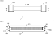
- FIG. 1 is a diagram illustrating a schematic configuration of a filter unit 10 according to the present embodiment.
- the filter unit 10 is configured to be connected to a device outside the filter unit 10 and to remove a contamination gas included in compressed air discharged by the device.
- the contamination gas include: hydrogen sulfide; SOx; NOx; hydrogen chloride; hydrogen fluoride; acetic acid; formic acid; nitric acid; sulfuric acid; ammonia; amine-based substances; chlorine; ozone; hydrogen peroxide; and organic substances such as hydrocarbons, fatty acids, silanol, and siloxane.
- the filter unit 10 includes a tube 100, a first joint 110, and a second joint 120.
- the tube 100 is a flexible tubular member.
- the tube 100 is made of urethane, fluorine, polyolefin, nylon, or formed by a laminate of such materials. That is, the tube 100 is constituted from a thermoplastic resin, for example.
- the tube 100 can be easily bent because the tube 100 is formed by a flexible member.
- the thermoplastic resin constituting the tube 100 is preferably a pressure-resistant material.
- the tube 100 is preferably a pressure-resistant tube.
- the present inventor(s) found that, compared to a case in which contamination gases are removed under atmospheric pressure, contamination gases can be more efficiently removed and the service life of the tube 100 is increased by discharging pressurized atmospheric air or additionally pressurized compressed air to the filter unit 10.
- the maximum pressure of the pressurized compressed air is 0.7 MPa.
- the pressure-resistant thermoplastic resin is a special thermoplastic elastomer, urethane, fluorine, polyolefin, or nylon.
- the first joint 110 and the second joint 120 are respectively connected to one end portion and the other end portion in the length direction of the tube 100.
- the one end portion and the other end portion in the length direction of the tube 100 are respectively referred to as a first end portion 101 (see FIG. 2 ) and a second end portion 102 (see FIG. 2 ).
- a pipe such as the tube 100 can be connected from two directions to each of the first and second joints 110 and 120.
- the first and second joints 110 and 120 are so-called quick joints.
- a pipe such as the tube 100 can be easily connected from two directions to each of the first and second joints 110 and 120.
- a device that discharges compressed air is directly or indirectly connected to one of the first and second joints 110 and 120.
- the device include: an air compressor; an N 2 gas generator; a gas cylinder; and a pump such as a vacuum pump or a compression pump.
- the device and the one of the first and second joints 110 and 120 are connected via a tube, for example.
- a pipe such as a tube is connected to the other one of the first and second joints 110 and 120, for example, and the compressed air discharged by the pipe is supplied to a target object.
- the target object include: a vacuum dryer in a pharmaceutical factory; an exhibition case installed in an art museum; a household fuel cell; or a computer, a control board, a power board, a power distribution board, or a control panel installed in a data center.
- the target object also include a computer, a control board, a power board, a power distribution board, or a control panel installed in a chemical plant, a paper mill, a water and wastewater treatment plant, a geothermal power plant, a thermal power plant, a spa, or the like.
- FIG. 2 is a diagram schematically illustrating a portion excluding the first and second joints 110 and 120 in a cross-section taken along line II-II in FIG. 1 .
- the filter unit 10 (see FIG. 1 ) further includes a chemical filter CF1 and a plurality of (two) caps 200.
- the chemical filter CF1 is made of a material that can remove the contamination gas included in the compressed air.
- the chemical filter CF1 include: activated charcoal; an ion exchange resin; activated alumina impregnated with an oxidant; zeolite; silica gel; mesoporous silica; a molecular sieve; a metal catalyst; sintered metal; and a photocatalyst.
- the tube 100 is filled with the chemical filter CF1.
- a cap 200 including a mesh portion 240 is attached to each of the two end portions in the length direction of the tube 100.
- the mesh portion 240 may include mesh and an air filter medium, or may only include mesh.
- the mesh portion 240 has a mesh size that does not allow the element forming the chemical filter CF1 (e.g., activated charcoal or the like) to flow outside of the cap 200.
- FIG. 3 is a perspective view of the cap 200.
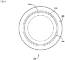
- FIG. 4 is a diagram illustrating the cap 200 from a front end side thereof. Note that the mesh portion 240 is omitted from FIG. 4 .
- FIG. 5 is a lateral view of the cap 200.
- the cap 200 includes a tubular portion 210, a flange portion 230, and the mesh portion 240.
- the tubular portion 210 has a circular shape in a plan view.
- a front end portion 210A (see FIG. 5 ) of the tubular portion 210 is inserted into openings 101X and 102X (see FIG. 2 ) respectively provided in the first and second end portions 101 and 102 in the length direction of the tube 100.
- the flange portion 230 is formed on a rear end portion 210B of the tubular portion 210, and extends radially outward of the tubular portion 210.
- a front-end-side surface of the flange portion 230 is in contact with rims of the openings 101X and 102X.
- the tubular portion 210 and the flange portion 230 are integrally formed using a resin.
- the tubular portion 210 is provided with a tapered portion 220 and a straight portion 250.
- the tapered portion 220 expands radially outward of the tubular portion 210 commensurately as a distance to the rear end portion 210B of the tubular portion 210 decreases.
- the straight portion 250 is formed between the tapered portion 220 and the flange portion 230.
- the straight portion 250 has a constant outer diameter between the tapered portion 220 and the rear end portion 210B of the tubular portion 210. The reason as to why the tubular portion 210 is provided with the tapered portion 220 will be explained next.
- the cap 200 cannot be connected to the tube 100 properly if the tubular portion 210 is completely straight.
- the cap 200 cannot be connected to the tube 100 properly if the inner diameter of the tube 100 is greater than the outer diameter of the tubular portion 210.
- the tubular portion 210 in the filter unit 10 is provided with the tapered portion 220, the tapered portion 220 comes into contact with the inner circumferential surface of the tube 100 even if there is a slight difference in the inner diameter of the tube 100 due to an individual difference.
- the cap 200 can be connected to the tube 100 properly even if there is an individual difference in the tube 100.
- a length L2 of the flange portion 230 is shorter than a length L1 of the portion of the tubular portion 210 where the tapered portion 220 is formed. The reason why such a configuration is adopted will be explained next.
- An increase in the length L2 of the flange portion 230 in the length direction of the tube 100 results in weaker connection strength between the tube 100 and the first and second joints 110 and 120 because the tube 100 cannot be moved to a sufficiently deep position in the first and second joints 110 and 120.
- the length L2 of the flange portion 230 is shorter than the length L1 of the portion of the tubular portion 210 where the tapered portion 220 is formed.
- the connection strength between the first and second joints 110 and 120 and the tube 100 can be kept at a sufficient level because the tube 100 can be moved to a sufficiently deep position in the first and second joints 110 and 120.
- the mesh portion 240 is a mesh-shaped member.
- the mesh portion 240 is affixed to a rear-end-side surface of the flange portion 230.
- the mesh portion 240 and the flange portion 230 may be adhered to one another using an adhesive, or may be welded together through ultrasonic welding.
- the caps 200 each including the mesh portion 240 are respectively connected to the openings 101X and 102X of the tube 100.
- the chemical filter CF1 can be kept inside the tube 100 without blocking the path of the compressed air.
- FIG. 6 is a diagram schematically illustrating the vicinity of the second joint 120 in the cross-section taken along line II-II in FIG. 1 .
- the cross-sectional structure of the second joint 120 is omitted with the exception of a seal portion SL1.
- the cap 200 is attached to the second end portion 102 in the length direction of the tube 100.
- the second joint 120 is attached to the tube 100 so as to cover the second end portion 102 and the cap 200. Sealing between the tube 100 and the second joint 120 is established by the seal portion SL1.
- the seal portion SL1 is formed by a rubber ring.
- a length LA from a front end portion P2 (210A) to a rear end portion P3 of the cap 200 is shorter than a length LB from the seal portion SL1 (P1) to the rear end portion P3 of the cap 200.
- the front end portion P2 (210A) of the cap 200 does not reach the position of the seal portion SL1.
- the sealing performance between the second joint 120 and the tube 100 may be affected depending on the material and outer diameter of the cap 200.
- the length LA from the front end portion P2 (210A) to the rear end portion P3 of the cap 200 is shorter than the length LB from seal portions (e.g., the seal portion SL1) that establish sealing between the tube 100 and the first and second joints 110 and 120 to the rear end portion P3 of the cap 200.
- the sealing performance between the tube 100 and the first and second joints 110 and 120 can be kept at a sufficient level because the front end portion P2 (210A) of the cap 200 does not reach the seal portion SL1 establishing sealing between the tube 100 and the first and second joints 110 and 120.
- FIG. 7 is a flowchart illustrating a procedure for manufacturing the filter unit 10. Each step shown in this flowchart is performed by a worker.
- the worker attaches the cap 200 to the second end portion 102 of the tube 100, and fills the tube 100 with the chemical filter CF1 (step S100).
- the worker attaches the cap 200 to the first end portion 101 of the tube 100 (step S110).
- the worker respectively attaches the first joint 110 and the second joint 120 to the first end portion 101 and the second end portion 102 of the tube 100 having the caps 200 attached to each of the first end portion 101 and the second end portion 102 (step S120).
- the manufacturing of the filter unit 10 is complete.
- the tube 100 is flexible, and the first joint 110 and the second joint 120 are respectively connected to the first end portion 101 and the second end portion 102 of the tube 100.
- the filter unit 10 can be installed relatively easily even if there is a limitation on installation space and the like because the tube 100 can be easily deformed and also because the tube 100 and a device or the like that discharges compressed air can be easily connected to each other.
- a filter unit 10X according to embodiment 2 differs from the filter unit 10 according to embodiment 1 in that the filter unit 10X includes a cap 200X, whereas the rest of the configurations are the same as those in embodiment 1.
- the filter unit 10X according to embodiment 2 will be described focusing on portions that differ from embodiment 1.
- FIG. 8 is a cross-sectional view illustrating the second end portion 102 and the vicinity thereof in the filter unit 10X.
- FIG. 9 is a lateral view of the cap 200X.
- FIG. 10 is a front view of the cap 200X. Note that illustration of the second joint 120 is omitted from FIG. 8 .
- the cap 200X includes a tubular portion 210X, a flange portion 230X, and a mesh portion 240X.
- the tubular portion 210X has a circular shape in a plan view.
- a front end portion 210XA of the tubular portion 210X is inserted into openings 101X and 102X (see FIG. 2 ) respectively provided in the first and second end portions 101 and 102 in the length direction of the tube 100.
- the tubular portion 210X has a constant outer diameter XA (see FIG. 9 ) between the front end portion 210XA and a rear end portion 210YA.
- the outer diameter XA is smaller than an inner diameter XB (see FIG. 8 ) of the tube 100.
- a clearance 300 is formed between the inner circumferential surface of the tube 100 and a portion of the tubular portion 210X that faces the inner circumferential surface of the tube 100.
- the clearance 300 is of a size that does not allow the element forming the chemical filter CF1 (e.g., activated charcoal or the like) to flow outside of the tube 100.
- the cap 200X is held by the first and second joints 110 and 120 because the first joint 110 and the second joint 120 are respectively connected to the first end portion 101 and the second end portion 102 of the tube 100. Thus, the cap 200X does not come loose from the tube 100 when the filter unit 10X is being used.
- the flange portion 230X is formed on the rear end portion 210YA of the tubular portion 210X, and extends radially outward of the tubular portion 210X.
- a front-end-side surface of the flange portion 230X is in contact with rims of the openings 101X and 102X.
- An outer diameter XC of the flange portion 230X is slightly smaller than an outer diameter XD of the tube 100.
- the flange portion 230X is positioned inward of the outline of the tube 100.
- the cap 200X and the first and second joints 110 and 120 are less likely to interfere with one another when the first and second joints 110 and 120 are connected to the tube 100.
- the tubular portion 210X and the flange portion 230X are integrally formed using a resin.
- the resin is polypropylene or polyester.
- the material forming the tubular portion 210X and the flange portion 230X is preferably a transparent polypropylene. If the material forming the tubular portion 210X and the flange portion 230X is a transparent polypropylene, the state of welding between the tubular portion 210X, the flange portion 230X, and the mesh portion 240X can be easily checked.
- the mesh portion 240X is formed between the front end portion 210XA and the rear end portion 210YA of the tubular portion 210X.
- the position of the tubular portion 210X where the mesh portion 240X is to be formed can be selected as desired.
- the mesh portion 240X is preferably provided at a position of the tubular portion 210X that is close to the rear end portion 210YA.
- the mesh portion 240X is formed integrally with the tubular portion 210X and the flange portion 230X.
- the cap 200X is manufactured by the tubular portion 210X and the flange portion 230X being injection molded onto the mesh portion 240X inserted into a mold for molding the tubular portion 210X and the flange portion 230X.
- the cap 200X may be manufactured through cutting or using a forming method involving the use of a 3D printer or the like.
- the material forming the mesh portion 240X is a resin. In order to suppress outgassing, the material forming the mesh portion 240 is preferably polyester.
- the mesh portion 240X has a mesh size that does not allow the element forming the chemical filter CF1 (e.g., activated charcoal or the like) to flow outside of the cap 200X.
- the cap 200X can be easily manufactured because the outer diameter XA of the tubular portion 210X of the cap 200X is constant. Furthermore, in a case in which the particle diameter of the element forming the chemical filter CF1 (e.g., activated charcoal or the like) is large to a certain extent, the activated charcoal or the like is unlikely to flow to the outside even if the clearance 300 is formed between the cap 200X and the tube 100. Thus, the cap 200X, which can be easily manufactured, can be suitably used as in the present embodiment.
- the element forming the chemical filter CF1 e.g., activated charcoal or the like
- the present inventor(s) manufactured an example filter unit and carried out first and second tests.
- the example filter unit was a filter unit according to embodiment 1, and the tube was a pressure-resistant tube.
- the example filter unit had an outer diameter of 12.7 mm and an inner diameter of 9.56 mm.
- the first test was a test for checking contamination-gas removal efficiency when the compressed air is pressurized.
- the second test was a test for checking the filter-unit lifetime when the compressed air is pressurized. Note that, for convenience of description, description is provided in the following with the same reference symbols as those in embodiment 1 given to elements constituting the example filter unit that are the same as those in embodiment 1.
- the concentration of the contamination gas included in the upstream-side compressed air was the concentration of the contamination gas included in the compressed air discharged from the device.
- the concentration of the contamination gas included in the downstream-side compressed air was the concentration of the contamination gas included in the compressed air after passing through the filter unit 10.
- the contamination gas was toluene or total organic carbon (TOC).
- the pressure of the pressurized compressed air was 0.1 MPa, 0.2 MPa, 0.3 MPa, 0.4 MPa, and 0.5 MPa.
- the test flow rate was 100 NL/min under atmospheric pressure.
- FIG. 11 is a table showing the results of the first test.
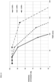
- FIG. 12 is a graph showing the results of the first test.
- FIG. 13 is a table showing the results of the second test.
- FIG. 14 is a graph showing the results of the second test. The removal efficiency in FIG. 13 was calculated using Formula (1) described in the description regarding the first test.
- the filter unit 10 includes one tube 100.
- the number of tubes 100 included in the filter unit 10 may be two or three. That is, a plurality of tubes 100 may be included in the filter unit 10.
- FIG. 15 is a diagram illustrating a schematic configuration of a filter unit 10A in a modification.
- FIG. 16 is a partial cross-sectional view of a first joint 110A in the filter unit 10A.
- the filter unit 10A includes two tubes 100A, a first joint 110A, and a second joint 120A.
- the chemical filter CF1 is included in each tube 100A, and the caps 200 are respectively attached to the openings in the two end portions of each tube 100A.
- the first joint 110A integrates the first end portions 101 of the plurality of tubes 100A.
- the first joint 110A includes a plurality of tube connection portions 111A that are connected to the first end portions 101 of the tubes 100A, and one device connection portion 111B to which a device that discharges compressed air is directly or indirectly connected.
- the second joint 120A integrates the second end portions 102 of the plurality of tubes 100A.
- the second joint 120A has the same structure as the first joint 110A.
- the second joint 120A includes a plurality of tube connection portions 121A and one device connection portion 121B.
- the chemical filter CF1 is distributed between the plurality of tubes 100A.
- the tubes 100A can be made narrower compared to when there is only one tube 100. Consequently, according to the filter unit 10A, the filter unit 10A can be made more readily bendable and smaller.
- the shape of the cap 200 in above-described embodiment 1 is not limited to the shape illustrated in FIGS. 3 , 4 , and 5 .
- the tapered portion 220 does not necessarily have to be provided on the cap 200.
- the tapered portion 220 may be formed over the entire tubular portion 210 from the front end portion 210A to the rear end portion 210B, or may be formed only near the rear end portion 210B, for example.
- first and second joints 110 and 120 are so-called quick joints.
- first and second joints 110 and 120 do not necessarily have to be quick joints.
- the first and second joints 110 and 120 may each be any kind of joint as long as pipes can be connected thereto from two directions.
- the mesh portion 240X is formed between the front end portion 210XA and the rear end portion 210YA of the tubular portion 210X.
- the position of the cap 200X where the mesh portion 240 is formed may be changed as appropriate.
- the mesh portion 240 may be formed in the flange portion 230X, or may be formed so as to span between the flange portion 230X and the tubular portion 210X.
Landscapes
- Chemical & Material Sciences (AREA)
- Chemical Kinetics & Catalysis (AREA)
- Engineering & Computer Science (AREA)
- Analytical Chemistry (AREA)
- General Chemical & Material Sciences (AREA)
- Oil, Petroleum & Natural Gas (AREA)
- General Engineering & Computer Science (AREA)
- Mechanical Engineering (AREA)
- Filtering Of Dispersed Particles In Gases (AREA)
Abstract
Description
- The present invention relates to a filter unit.
-
JP 2006-263545A - Patent Literature 1:
JP 2006-263545A - In order to use a filter unit that is configured to remove a specific gas, a space for installing the filter unit needs to be secured. Furthermore, an access route for installing and removing the filter unit (a space through which the filter unit can be taken in and out of a device or the like to which the filter unit is to be attached) needs to be secured. However, it is not necessarily the case that a sufficiently large installation space and the like (installation space and access route) for a filter unit can be secured, and there is often a limitation on the installation space and the like. Above-described Patent Literature 1 does not disclose any means for solving such a problem.
- The present invention has been made in order to solve such a problem, and an object thereof is to provide a filter unit that can be installed relatively easily even if there is a limitation on installation space and the like.
- A filter unit according to one aspect of the present invention includes: a tube; a chemical filter; a first joint; and a second joint. The tube includes a first end portion and a second end portion, and is flexible. The chemical filter is housed inside the tube. The first joint is connected to the first end portion of the tube. The second joint is connected to the second end portion of the tube. The first joint is configured to be directly or indirectly connected to a device that discharges compressed air.
- In this filter unit, the tube is flexible, and joints are connected to the two end portions of the tube. Thus, according to this filter unit, the filter unit can be installed relatively easily even if there is a limitation on installation space and the like because the tube can be easily deformed and also because the tube and a device or the like that discharges compressed air can be connected easily.
- In the above-described filter unit, the first and second joints may be quick joints.
- Thus, according to this filter unit, the tube and the device or the like that discharges compressed air can be easily connected to each other.
- In the above-described filter unit, the first and second end portions may may be respectively provided with openings, the filter unit may further include caps that are respectively attached to the openings, the cap may include: a tubular portion having a front end portion thereof inserted into the opening; a flange portion that is formed on a rear end portion of the tubular portion and that is in contact with a rim of the opening; and a mesh portion that is attached to the flange portion and that covers the opening, and the mesh portion may include mesh and an air filter medium.
- In this filter unit, caps including a mesh portion are respectively connected to the openings of the tube. Thus, according to this filter unit, the chemical filter can be kept inside the tube without blocking the path of the compressed air.
- In the above-described filter unit, the tubular portion may be provided with a tapered portion that expands radially outward of the tubular portion commensurately as a distance to the rear end portion decreases.
- Because individual differences may occur between tubes, depending on the inner diameter of the tube, there may be cases in which the cap cannot be connected to the tube properly if the tubular portion is completely straight. Because the cap in this filter unit is provided with a tapered portion, the tapered portion comes into contact with the inner circumferential surface of the tube even if there is a slight difference in the inner diameter of the tube due to an individual difference. Thus, according to this filter unit, the cap can be connected to the tube properly even if there is an individual difference in the tube.
- In the above-described filter unit, a length from the front end portion to the rear end portion may be shorter than a length to the rear end portion from a seal portion that establishes sealing between the first joint and the tube.
- If the front end portion of the cap reaches a seal portion that establishes sealing between a joint and the tube, the sealing performance between the joint and the tube may be affected depending on the material and diameter of the cap. In this filter unit, the length from the front end portion to the rear end portion is shorter than the length to the rear end portion from the seal portion establishing sealing between the first joint and the tube. Thus, according to this filter unit, because the front end portion of the cap does not reach the seal portion establishing sealing between a joint and the tube, the sealing performance between the joint and the tube can be can be kept at a sufficient level.
- In the above-described filter unit, in a length direction of the tube, a length of the flange portion may be shorter than a length of a portion of the tubular portion where the tapered portion is formed.
- An increase in the length of the flange portion in the length direction of the tube results in weaker connection strength and sealing performance between the joints and the tube. In this filter unit, in the length direction of the tube, the length of the flange portion is shorter than the length of the portion of the tubular portion where the tapered portion is formed. Thus, according to this filter unit, the connection strength and sealing performance between the joints and the tube can be kept at a sufficient level.
- In the above-described filter unit, the tube may be a pressure-resistant tube.
- The present inventor(s) found that, compared to cases in which contamination gases are removed under atmospheric pressure, contamination gases can be more efficiently removed by discharging pressurized atmospheric air or additionally pressurized compressed air to the
filter unit 10. According to this filter unit, contamination gases included in pressurized atmospheric air or pressurized compressed air can be removed because the tube is a pressure-resistant tube. Thus, contamination gases can be efficiently removed. - In the above-described filter unit, the first and second end portions may be respectively provided with openings, the filter unit may further include caps that are respectively attached to the openings, the cap may include: a tubular portion having a front end portion thereof inserted into the opening; and a flange portion that is formed on a rear end portion of the tubular portion and that is in contact with a rim of the opening, and the tubular portion may have a constant outer diameter between the front end portion and the rear end portion.
- According to this filter unit, the cap can be easily manufactured.
- In the above-described filter unit, the cap includes a mesh portion that is formed integrally with at least one of the tubular portion and the flange portion so as to cover the opening.
- According to this filter unit, the mesh portion is unlikely to come loose.
- A filter unit according to another aspect of the present invention includes: a plurality of tubes; a chemical filter; a first joint; and a second joint. Each of the plurality of tubes includes a first end portion and a second end portion, and is flexible. The chemical filter is housed inside each of the plurality of tubes. The first joint integrates the first end portions of the plurality of tubes. The second joint integrates the second end portions of the plurality of tubes. The first joint is configured to be directly or indirectly connected to a device that discharges compressed air.
- In this filter unit, the chemical filter is distributed between a plurality of tubes. Thus, if the amount of the chemical filter is the same, the tubes can be made narrower compared to when there is only one tube. Consequently, according to this filter unit, the filter unit can be made more readily bendable and thinner.
- According to the present invention, a filter unit that can be installed relatively easily even if there is a limitation on installation space and the like can be provided.
-
-
FIG. 1 is a diagram illustrating a schematic configuration of a filter unit according to embodiment 1. -
FIG. 2 is a diagram schematically illustrating a portion excluding joints in a cross-section taken along line II-II inFIG. 1 . -
FIG. 3 is a perspective view of a cap. -
FIG. 4 is a diagram illustrating the cap from a front end side thereof. -
FIG. 5 is a lateral view of the cap. -
FIG. 6 is a diagram schematically illustrating the vicinity of a joint in the cross-section taken along line II-II inFIG. 1 . -
FIG. 7 is a flowchart illustrating a procedure for manufacturing the filter unit. -
FIG. 8 is a diagram schematically illustrating a second end portion of a tube and the vicinity thereof in a filter unit according to embodiment 2. -
FIG. 9 is a lateral view of a cap illustrated inFIG. 8 . -
FIG. 10 is a front view of the cap illustrated inFIG. 8 . -
FIG. 11 is a table showing results of a first test. -
FIG. 12 is a graph showing the results of the first test. -
FIG. 13 is a table showing results of a second test. -
FIG. 14 is a graph showing the results of the second test. -
FIG. 15 is a diagram illustrating a schematic configuration of a filter unit in a modification. -
FIG. 16 is a diagram illustrating a partial cross-sectional structure of a first joint illustrated inFIG. 15 . - Embodiments of the present invention will be described in detail below with reference to the drawings. Note that the same reference symbol is given to portions in the drawings that are the same as or equivalent to one another, and description thereof will not be repeated.
-
FIG. 1 is a diagram illustrating a schematic configuration of afilter unit 10 according to the present embodiment. For example, thefilter unit 10 is configured to be connected to a device outside thefilter unit 10 and to remove a contamination gas included in compressed air discharged by the device. For example, examples of the contamination gas include: hydrogen sulfide; SOx; NOx; hydrogen chloride; hydrogen fluoride; acetic acid; formic acid; nitric acid; sulfuric acid; ammonia; amine-based substances; chlorine; ozone; hydrogen peroxide; and organic substances such as hydrocarbons, fatty acids, silanol, and siloxane. - As illustrated in
FIG. 1 , thefilter unit 10 includes atube 100, a first joint 110, and asecond joint 120. Thetube 100 is a flexible tubular member. For example, thetube 100 is made of urethane, fluorine, polyolefin, nylon, or formed by a laminate of such materials. That is, thetube 100 is constituted from a thermoplastic resin, for example. Thetube 100 can be easily bent because thetube 100 is formed by a flexible member. - The thermoplastic resin constituting the
tube 100 is preferably a pressure-resistant material. In other words, thetube 100 is preferably a pressure-resistant tube. The present inventor(s) found that, compared to a case in which contamination gases are removed under atmospheric pressure, contamination gases can be more efficiently removed and the service life of thetube 100 is increased by discharging pressurized atmospheric air or additionally pressurized compressed air to thefilter unit 10. For example, the maximum pressure of the pressurized compressed air is 0.7 MPa. For example, the pressure-resistant thermoplastic resin is a special thermoplastic elastomer, urethane, fluorine, polyolefin, or nylon. - The first joint 110 and the second joint 120 are respectively connected to one end portion and the other end portion in the length direction of the
tube 100. In the following, the one end portion and the other end portion in the length direction of thetube 100 are respectively referred to as a first end portion 101 (seeFIG. 2 ) and a second end portion 102 (seeFIG. 2 ). A pipe such as thetube 100 can be connected from two directions to each of the first andsecond joints second joints tube 100 can be easily connected from two directions to each of the first andsecond joints - For example, a device that discharges compressed air (pressurized air) is directly or indirectly connected to one of the first and
second joints second joints second joints - Furthermore, a pipe such as a tube is connected to the other one of the first and
second joints -
FIG. 2 is a diagram schematically illustrating a portion excluding the first andsecond joints FIG. 1 . As illustrated inFIG. 2 , the filter unit 10 (seeFIG. 1 ) further includes a chemical filter CF1 and a plurality of (two) caps 200. - The chemical filter CF1 is made of a material that can remove the contamination gas included in the compressed air. Examples of the chemical filter CF1 include: activated charcoal; an ion exchange resin; activated alumina impregnated with an oxidant; zeolite; silica gel; mesoporous silica; a molecular sieve; a metal catalyst; sintered metal; and a photocatalyst. The
tube 100 is filled with the chemical filter CF1. Thus, the contamination gas included in the compressed air passing through thetube 100 is removed. Acap 200 including amesh portion 240 is attached to each of the two end portions in the length direction of thetube 100. For example, themesh portion 240 may include mesh and an air filter medium, or may only include mesh. Themesh portion 240 has a mesh size that does not allow the element forming the chemical filter CF1 (e.g., activated charcoal or the like) to flow outside of thecap 200. -
FIG. 3 is a perspective view of thecap 200.FIG. 4 is a diagram illustrating thecap 200 from a front end side thereof. Note that themesh portion 240 is omitted fromFIG. 4 .FIG. 5 is a lateral view of thecap 200. - With reference to
FIGS. 3 ,4 , and5 , thecap 200 includes atubular portion 210, aflange portion 230, and themesh portion 240. Thetubular portion 210 has a circular shape in a plan view. Afront end portion 210A (seeFIG. 5 ) of thetubular portion 210 is inserted intoopenings FIG. 2 ) respectively provided in the first andsecond end portions tube 100. Theflange portion 230 is formed on arear end portion 210B of thetubular portion 210, and extends radially outward of thetubular portion 210. In a state in which thecap 200 is attached to thetube 100, a front-end-side surface of theflange portion 230 is in contact with rims of theopenings tubular portion 210 and theflange portion 230 are integrally formed using a resin. - The
tubular portion 210 is provided with a taperedportion 220 and astraight portion 250. The taperedportion 220 expands radially outward of thetubular portion 210 commensurately as a distance to therear end portion 210B of thetubular portion 210 decreases. Thestraight portion 250 is formed between thetapered portion 220 and theflange portion 230. Thestraight portion 250 has a constant outer diameter between thetapered portion 220 and therear end portion 210B of thetubular portion 210. The reason as to why thetubular portion 210 is provided with the taperedportion 220 will be explained next. - Because individual differences may occur between
tubes 100, depending on the inner diameter of thetube 100, there may be cases in which thecap 200 cannot be connected to thetube 100 properly if thetubular portion 210 is completely straight. For example, thecap 200 cannot be connected to thetube 100 properly if the inner diameter of thetube 100 is greater than the outer diameter of thetubular portion 210. Because thetubular portion 210 in thefilter unit 10 is provided with the taperedportion 220, the taperedportion 220 comes into contact with the inner circumferential surface of thetube 100 even if there is a slight difference in the inner diameter of thetube 100 due to an individual difference. Thus, according to thefilter unit 10, thecap 200 can be connected to thetube 100 properly even if there is an individual difference in thetube 100. - Furthermore, in the
cap 200, in the length direction of thetube 100, a length L2 of theflange portion 230 is shorter than a length L1 of the portion of thetubular portion 210 where the taperedportion 220 is formed. The reason why such a configuration is adopted will be explained next. - An increase in the length L2 of the
flange portion 230 in the length direction of thetube 100 results in weaker connection strength between thetube 100 and the first andsecond joints tube 100 cannot be moved to a sufficiently deep position in the first andsecond joints filter unit 10, in the length direction of thetube 100, the length L2 of theflange portion 230 is shorter than the length L1 of the portion of thetubular portion 210 where the taperedportion 220 is formed. Thus, according to thefilter unit 10, the connection strength between the first andsecond joints tube 100 can be kept at a sufficient level because thetube 100 can be moved to a sufficiently deep position in the first andsecond joints - The
mesh portion 240 is a mesh-shaped member. Themesh portion 240 is affixed to a rear-end-side surface of theflange portion 230. For example, themesh portion 240 and theflange portion 230 may be adhered to one another using an adhesive, or may be welded together through ultrasonic welding. - With reference to
FIG. 2 once again, in thefilter unit 10, thecaps 200 each including themesh portion 240 are respectively connected to theopenings tube 100. Thus, according to thefilter unit 10, the chemical filter CF1 can be kept inside thetube 100 without blocking the path of the compressed air. -
FIG. 6 is a diagram schematically illustrating the vicinity of the second joint 120 in the cross-section taken along line II-II inFIG. 1 . Note that, inFIG. 6 , the cross-sectional structure of the second joint 120 is omitted with the exception of a seal portion SL1. As illustrated inFIG. 6 , thecap 200 is attached to thesecond end portion 102 in the length direction of thetube 100. The second joint 120 is attached to thetube 100 so as to cover thesecond end portion 102 and thecap 200. Sealing between thetube 100 and the second joint 120 is established by the seal portion SL1. For example, the seal portion SL1 is formed by a rubber ring. - In the
filter unit 10, a length LA from a front end portion P2 (210A) to a rear end portion P3 of thecap 200 is shorter than a length LB from the seal portion SL1 (P1) to the rear end portion P3 of thecap 200. In other words, the front end portion P2 (210A) of thecap 200 does not reach the position of the seal portion SL1. - If the front end portion P2 (210A) of the
cap 200 reaches the seal portion SL1, the sealing performance between the second joint 120 and thetube 100 may be affected depending on the material and outer diameter of thecap 200. In thefilter unit 10, the length LA from the front end portion P2 (210A) to the rear end portion P3 of thecap 200 is shorter than the length LB from seal portions (e.g., the seal portion SL1) that establish sealing between thetube 100 and the first andsecond joints cap 200. According to thefilter unit 10, the sealing performance between thetube 100 and the first andsecond joints cap 200 does not reach the seal portion SL1 establishing sealing between thetube 100 and the first andsecond joints -
FIG. 7 is a flowchart illustrating a procedure for manufacturing thefilter unit 10. Each step shown in this flowchart is performed by a worker. - With reference to
FIG. 7 , the worker attaches thecap 200 to thesecond end portion 102 of thetube 100, and fills thetube 100 with the chemical filter CF1 (step S100). The worker attaches thecap 200 to thefirst end portion 101 of the tube 100 (step S110). The worker respectively attaches the first joint 110 and the second joint 120 to thefirst end portion 101 and thesecond end portion 102 of thetube 100 having thecaps 200 attached to each of thefirst end portion 101 and the second end portion 102 (step S120). Thus, the manufacturing of thefilter unit 10 is complete. - As described above, in the
filter unit 10 according to the present embodiment, thetube 100 is flexible, and the first joint 110 and the second joint 120 are respectively connected to thefirst end portion 101 and thesecond end portion 102 of thetube 100. Thus, according to thefilter unit 10, thefilter unit 10 can be installed relatively easily even if there is a limitation on installation space and the like because thetube 100 can be easily deformed and also because thetube 100 and a device or the like that discharges compressed air can be easily connected to each other. - A
filter unit 10X according to embodiment 2 differs from thefilter unit 10 according to embodiment 1 in that thefilter unit 10X includes acap 200X, whereas the rest of the configurations are the same as those in embodiment 1. In the following, thefilter unit 10X according to embodiment 2 will be described focusing on portions that differ from embodiment 1. -
FIG. 8 is a cross-sectional view illustrating thesecond end portion 102 and the vicinity thereof in thefilter unit 10X.FIG. 9 is a lateral view of thecap 200X.FIG. 10 is a front view of thecap 200X. Note that illustration of the second joint 120 is omitted fromFIG. 8 . - The
cap 200X includes atubular portion 210X, aflange portion 230X, and amesh portion 240X. Thetubular portion 210X has a circular shape in a plan view. A front end portion 210XA of thetubular portion 210X is inserted intoopenings FIG. 2 ) respectively provided in the first andsecond end portions tube 100. Thetubular portion 210X has a constant outer diameter XA (seeFIG. 9 ) between the front end portion 210XA and a rear end portion 210YA. Thus, thecap 200X can be easily manufactured. The outer diameter XA is smaller than an inner diameter XB (seeFIG. 8 ) of thetube 100. Thus, aclearance 300 is formed between the inner circumferential surface of thetube 100 and a portion of thetubular portion 210X that faces the inner circumferential surface of thetube 100. Theclearance 300 is of a size that does not allow the element forming the chemical filter CF1 (e.g., activated charcoal or the like) to flow outside of thetube 100. Thecap 200X is held by the first andsecond joints first end portion 101 and thesecond end portion 102 of thetube 100. Thus, thecap 200X does not come loose from thetube 100 when thefilter unit 10X is being used. - The
flange portion 230X is formed on the rear end portion 210YA of thetubular portion 210X, and extends radially outward of thetubular portion 210X. In a state in which thecap 200X is attached to thetube 100, a front-end-side surface of theflange portion 230X is in contact with rims of theopenings flange portion 230X is slightly smaller than an outer diameter XD of thetube 100. In a state in which thecap 200X is attached to thetube 100, theflange portion 230X is positioned inward of the outline of thetube 100. Thus, thecap 200X and the first andsecond joints second joints tube 100. - For example, the
tubular portion 210X and theflange portion 230X are integrally formed using a resin. For example, the resin is polypropylene or polyester. In order to enhance rigidity, the material forming thetubular portion 210X and theflange portion 230X is preferably a transparent polypropylene. If the material forming thetubular portion 210X and theflange portion 230X is a transparent polypropylene, the state of welding between thetubular portion 210X, theflange portion 230X, and themesh portion 240X can be easily checked. - The
mesh portion 240X is formed between the front end portion 210XA and the rear end portion 210YA of thetubular portion 210X. Thus, the air permeability of thecap 200X is improved. The position of thetubular portion 210X where themesh portion 240X is to be formed can be selected as desired. In order to house the largest possible amount of the chemical filter CF1, themesh portion 240X is preferably provided at a position of thetubular portion 210X that is close to the rear end portion 210YA. - The
mesh portion 240X is formed integrally with thetubular portion 210X and theflange portion 230X. For example, thecap 200X is manufactured by thetubular portion 210X and theflange portion 230X being injection molded onto themesh portion 240X inserted into a mold for molding thetubular portion 210X and theflange portion 230X. For example, thecap 200X may be manufactured through cutting or using a forming method involving the use of a 3D printer or the like. For example, the material forming themesh portion 240X is a resin. In order to suppress outgassing, the material forming themesh portion 240 is preferably polyester. Themesh portion 240X has a mesh size that does not allow the element forming the chemical filter CF1 (e.g., activated charcoal or the like) to flow outside of thecap 200X. - As described above, in the
filter unit 10X according to the present embodiment, thecap 200X can be easily manufactured because the outer diameter XA of thetubular portion 210X of thecap 200X is constant. Furthermore, in a case in which the particle diameter of the element forming the chemical filter CF1 (e.g., activated charcoal or the like) is large to a certain extent, the activated charcoal or the like is unlikely to flow to the outside even if theclearance 300 is formed between thecap 200X and thetube 100. Thus, thecap 200X, which can be easily manufactured, can be suitably used as in the present embodiment. - The present inventor(s) manufactured an example filter unit and carried out first and second tests. The example filter unit was a filter unit according to embodiment 1, and the tube was a pressure-resistant tube. The example filter unit had an outer diameter of 12.7 mm and an inner diameter of 9.56 mm. The first test was a test for checking contamination-gas removal efficiency when the compressed air is pressurized. The second test was a test for checking the filter-unit lifetime when the compressed air is pressurized. Note that, for convenience of description, description is provided in the following with the same reference symbols as those in embodiment 1 given to elements constituting the example filter unit that are the same as those in embodiment 1.
- In the first test, compressed air discharged from a device that discharges compressed air was pressurized using a compressor, and the concentration of a contamination gas included in upstream-side compressed air and the concentration of the contamination gas included in downstream-side compressed air were measured. The concentration of the contamination gas included in the upstream-side compressed air was the concentration of the contamination gas included in the compressed air discharged from the device. The concentration of the contamination gas included in the downstream-side compressed air was the concentration of the contamination gas included in the compressed air after passing through the
filter unit 10. The contamination gas was toluene or total organic carbon (TOC). The pressure of the pressurized compressed air was 0.1 MPa, 0.2 MPa, 0.3 MPa, 0.4 MPa, and 0.5 MPa. The test flow rate was 100 NL/min under atmospheric pressure. -
FIG. 11 is a table showing the results of the first test.FIG. 12 is a graph showing the results of the first test. The removal efficiency inFIG. 11 was calculated using Formula (1) below.
- As shown in
FIGS. 11 and12 , it was confirmed that the higher the pressure of the pressurized compressed air, the higher the removal efficiency. Furthermore, it was confirmed that relatively high removal efficiency could be obtained even if the pressure of the compressed air is around 0.1 MPa. One reason why such results where obtained is because the volume of the compressed air decreases when the compressed air is pressurized, and thus the flow rate decreases and the contact time between the element forming the chemical filter CF1 (e.g., activated charcoal) and the compressed air increases. It is conceivable that the contamination gas was thus more readily adsorbed by the activated charcoal or the like. - In the second test, compressed air discharged from a device that discharges compressed air was pressurized using a compressor, and the discharge time of the compressed air, the concentration of a contamination gas included in upstream-side compressed air, and the concentration of the contamination gas included in downstream-side compressed air were measured. The concentration of the contamination gas included in the upstream-side compressed air and the concentration of the contamination gas included in the downstream-side compressed air were the same as those in the first test. The contamination gas was toluene. The pressure of the pressurized compressed air was 0.2 MPa, 0.3 MPa, and 0.5 MPa. The discharge time of the compressed air was two hours (120 min). Similarly to the first test, the test flow rate was 100 NL/min under atmospheric pressure.
-
FIG. 13 is a table showing the results of the second test.FIG. 14 is a graph showing the results of the second test. The removal efficiency inFIG. 13 was calculated using Formula (1) described in the description regarding the first test. - As shown in
FIGS. 13 and14 , it was confirmed that the higher the pressure of the pressurized compressed air, the more gradual the decrease of the removal efficiency in relation to the discharge time of the compressed air. In other words, it was confirmed that the higher the pressure of the pressurized compressed air, the longer the service life of thefilter unit 10. For example, the time it took for the removal efficiency to decrease to 66.7% was 87 min when the pressure of the compressed air was 0.2 MPa, 119 min when the pressure of the compressed air was 0.3 MPa, and 173 min when the pressure of the compressed air was 0.5 MPa. - While embodiments of the present invention have been described above, the present invention is not limited to the above-described embodiments, and various modifications can be made within the scope of the present invention. Modifications of the present invention are described below. Note that these modifications may be combined with one another as long no technical contradiction arises therebetween.
- In above-described embodiment 1, the
filter unit 10 includes onetube 100. However, the number oftubes 100 included in thefilter unit 10 may be two or three. That is, a plurality oftubes 100 may be included in thefilter unit 10. -
FIG. 15 is a diagram illustrating a schematic configuration of a filter unit 10A in a modification.FIG. 16 is a partial cross-sectional view of a first joint 110A in the filter unit 10A. As illustrated inFIG. 15 , the filter unit 10A includes twotubes 100A, a first joint 110A, and a second joint 120A. Similarly to thetube 100 in above-described embodiment 1, the chemical filter CF1 is included in eachtube 100A, and thecaps 200 are respectively attached to the openings in the two end portions of eachtube 100A. The first joint 110A integrates thefirst end portions 101 of the plurality oftubes 100A. The first joint 110A includes a plurality oftube connection portions 111A that are connected to thefirst end portions 101 of thetubes 100A, and onedevice connection portion 111B to which a device that discharges compressed air is directly or indirectly connected. The second joint 120A integrates thesecond end portions 102 of the plurality oftubes 100A. The second joint 120A has the same structure as the first joint 110A. The second joint 120A includes a plurality oftube connection portions 121A and onedevice connection portion 121B. - In the filter unit 10A, the chemical filter CF1 is distributed between the plurality of
tubes 100A. Thus, if the amount of the chemical filter CF1 is the same, thetubes 100A can be made narrower compared to when there is only onetube 100. Consequently, according to the filter unit 10A, the filter unit 10A can be made more readily bendable and smaller. - Furthermore, the shape of the
cap 200 in above-described embodiment 1 is not limited to the shape illustrated inFIGS. 3 ,4 , and5 . For example, the taperedportion 220 does not necessarily have to be provided on thecap 200. Alternatively, the taperedportion 220 may be formed over the entiretubular portion 210 from thefront end portion 210A to therear end portion 210B, or may be formed only near therear end portion 210B, for example. - Furthermore, in above-described embodiment 1, the first and
second joints second joints second joints - Furthermore, in above-described embodiment 2, the
mesh portion 240X is formed between the front end portion 210XA and the rear end portion 210YA of thetubular portion 210X. However, the position of thecap 200X where themesh portion 240 is formed may be changed as appropriate. For example, themesh portion 240 may be formed in theflange portion 230X, or may be formed so as to span between theflange portion 230X and thetubular portion 210X. -
- 10
- Filter unit
- 100
- Tube
- 101
- First end portion
- 101X
- Opening
- 102
- Second end portion
- 102X
- Opening
- 110
- First joint
- 120
- Second joint
- 200
- Cap
- 210
- Tubular portion
- 210A
- Front end portion
- 210XA
- Front end portion
- 210B
- Rear end portion
- 210YA
- Rear end portion
- 220
- Tapered portion
- 230
- Flange portion
- 240
- Mesh portion
- CF1
- Chemical filter
- SL1
- Seal portion
Claims (10)
- A filter unit comprising:a tube that includes a first end portion and a second end portion and that is flexible;a chemical filter that is housed inside the tube;a first joint that is connected to the first end portion of the tube; anda second joint that is connected to the second end portion of the tube,wherein the first joint is configured to be directly or indirectly connected to a device that discharges compressed air.
- The filter unit according to claim 1, wherein the first and second joints are quick joints.
- The filter unit according to claim 1 or 2,wherein the first and second end portions are respectively provided with openings,the filter unit further comprises caps that are respectively attached to the openings, andthe cap includes:a tubular portion having a front end portion thereof inserted into the opening;a flange portion that is formed on a rear end portion of the tubular portion and that is in contact with a rim of the opening; anda mesh portion that is attached to the flange portion and that covers the opening.
- The filter unit according to claim 3,
wherein the tubular portion is provided with a tapered portion that expands radially outward of the tubular portion commensurately as a distance to the rear end portion decreases. - The filter unit according to claim 3 or 4,
wherein a length from the front end portion to the rear end portion is shorter than a length to the rear end portion from a seal portion that establishes sealing between the first joint and the tube. - The filter unit according to claim 4,
wherein, in a length direction of the tube, a length of the flange portion is shorter than a length of a portion of the tubular portion where the tapered portion is formed. - The filter unit according to any of claims 1 to 6, wherein the tube is a pressure-resistant tube.
- The filter unit according to claim 2,wherein the first and second end portions are respectively provided with openings,the filter unit further comprises caps that are respectively attached to the openings,the cap includes:a tubular portion having a front end portion thereof inserted into the opening; anda flange portion that is formed on a rear end portion of the tubular portion and that is in contact with a rim of the opening, andthe tubular portion has a constant outer diameter between the front end portion and the rear end portion.
- The filter unit according to claim 8,
wherein the cap includes a mesh portion that is formed integrally with at least one of the tubular portion and the flange portion so as to cover the opening. - A filter unit comprising:a plurality of tubes each of which includes a first end portion and a second end portion, and is flexible;a chemical filter that is housed inside each of the plurality of tubes;a first joint that integrates the first end portions of the plurality of tubes; anda second joint that integrates the second end portions of the plurality of tubes,wherein the first joint is configured to be directly or indirectly connected to a device that discharges compressed air.
Applications Claiming Priority (2)
| Application Number | Priority Date | Filing Date | Title |
|---|---|---|---|
| JP2020175100 | 2020-10-19 | ||
| PCT/JP2021/038386 WO2022085618A1 (en) | 2020-10-19 | 2021-10-18 | Filter unit |
Publications (2)
| Publication Number | Publication Date |
|---|---|
| EP4230281A1 true EP4230281A1 (en) | 2023-08-23 |
| EP4230281A4 EP4230281A4 (en) | 2025-06-18 |
Family
ID=81290456
Family Applications (1)
| Application Number | Title | Priority Date | Filing Date |
|---|---|---|---|
| EP21882759.0A Pending EP4230281A4 (en) | 2020-10-19 | 2021-10-18 | FILTER UNIT |
Country Status (6)
| Country | Link |
|---|---|
| EP (1) | EP4230281A4 (en) |
| JP (1) | JPWO2022085618A1 (en) |
| KR (1) | KR20230051554A (en) |
| CN (1) | CN116348701A (en) |
| TW (1) | TWI904263B (en) |
| WO (1) | WO2022085618A1 (en) |
Families Citing this family (1)
| Publication number | Priority date | Publication date | Assignee | Title |
|---|---|---|---|---|
| KR20240154961A (en) | 2023-04-19 | 2024-10-28 | 주식회사 엘지에너지솔루션 | A self-supporting ceramic seperator for an electrochemical device and an electrochemical device comprising the same |
Family Cites Families (20)
| Publication number | Priority date | Publication date | Assignee | Title |
|---|---|---|---|---|
| JPS5193837U (en) * | 1975-03-03 | 1976-07-28 | ||
| JPS5381645U (en) * | 1976-12-10 | 1978-07-06 | ||
| JPH0474590U (en) * | 1990-10-22 | 1992-06-30 | ||
| JPH09196269A (en) * | 1996-01-19 | 1997-07-29 | Smc Corp | Joint |
| JP3641077B2 (en) * | 1996-08-12 | 2005-04-20 | 株式会社竹中工務店 | Filtration device |
| JPH10296054A (en) * | 1997-04-23 | 1998-11-10 | Koa Corp:Kk | Ozone decomposition device |
| JPH11221414A (en) * | 1998-02-09 | 1999-08-17 | Mitsubishi Electric Corp | Air purification filter unit |
| JP4176312B2 (en) * | 2001-01-18 | 2008-11-05 | 日本碍子株式会社 | Activated carbon pack for water purifier |
| WO2004016340A1 (en) * | 2002-08-16 | 2004-02-26 | Flow Dry Technology Ltd. | Desiccant cartridge with seal |
| US7285156B2 (en) * | 2004-03-15 | 2007-10-23 | Michael J. Arno | Inline, point-of-use air/gas dryness indicator |
| US7108740B2 (en) * | 2004-03-15 | 2006-09-19 | Michael J. Arno | Flexible, inline, point-of-use air/gas filter/dryer |
| US7407632B2 (en) * | 2004-05-28 | 2008-08-05 | Oxysure Systems, Inc. | Apparatus and delivery of medically pure oxygen |
| JP4498183B2 (en) | 2005-03-23 | 2010-07-07 | 株式会社東芝 | Hydrogen chloride gas absorbent and method for removing hydrogen chloride gas |
| US20060230629A1 (en) * | 2005-04-16 | 2006-10-19 | Arno Michael J | Wearable disposable dryer with carrying strap and stowage accessory |
| JP2007120671A (en) * | 2005-10-28 | 2007-05-17 | Ngk Spark Plug Co Ltd | Oxygen concentrator by pipe joint and pressure fluctuation adsorption method |
| US20080005919A1 (en) * | 2006-07-10 | 2008-01-10 | Brown Jerome R | In-line dryer |
| JP2012075994A (en) * | 2010-09-30 | 2012-04-19 | Toei Sangyo Kk | Harmful substance removing device, cleaning/purifying system for gas or liquid, and chemical reaction system of gas or liquid |
| US10695520B2 (en) * | 2011-04-22 | 2020-06-30 | Inogen, Inc. | Gas concentrator with removable cartridge adsorbent beds |
| JP2019051519A (en) * | 2018-12-19 | 2019-04-04 | 東芝エネルギーシステムズ株式会社 | Hydrogen treatment equipment |
| CN210237107U (en) * | 2019-06-21 | 2020-04-03 | 北京牧晨机电有限公司 | Composite sealing cap for loading and unloading crane pipe of train tank car and loading and unloading crane pipe |
-
2021
- 2021-10-18 EP EP21882759.0A patent/EP4230281A4/en active Pending
- 2021-10-18 CN CN202180067688.3A patent/CN116348701A/en active Pending
- 2021-10-18 TW TW110138576A patent/TWI904263B/en active
- 2021-10-18 KR KR1020237009024A patent/KR20230051554A/en active Pending
- 2021-10-18 JP JP2022557511A patent/JPWO2022085618A1/ja active Pending
- 2021-10-18 WO PCT/JP2021/038386 patent/WO2022085618A1/en not_active Ceased
Also Published As
| Publication number | Publication date |
|---|---|
| TWI904263B (en) | 2025-11-11 |
| EP4230281A4 (en) | 2025-06-18 |
| CN116348701A (en) | 2023-06-27 |
| KR20230051554A (en) | 2023-04-18 |
| WO2022085618A1 (en) | 2022-04-28 |
| TW202220744A (en) | 2022-06-01 |
| JPWO2022085618A1 (en) | 2022-04-28 |
Similar Documents
| Publication | Publication Date | Title |
|---|---|---|
| US8821619B2 (en) | Adsorbent cartridge assembly with end cap | |
| CN106356481B (en) | Non-aqueous secondary battery | |
| ES2247743T3 (en) | DEVICE FOR SEPARATION OF LIQUIDS. | |
| EP2704542B1 (en) | Ventilation unit | |
| US20170291129A1 (en) | Filter Assembly | |
| US20220344772A1 (en) | Venting Unit and Housing, in Particular Battery Housing | |
| WO2004069367A2 (en) | Filter assembly with spin-on filters and methods using the filter assembly | |
| KR20160130419A (en) | Gas-permeable member and breathable container | |
| EP2189696B1 (en) | Fiber-reinforced resin pipe | |
| JP5075669B2 (en) | Hollow fiber membrane module | |
| EP2572775A1 (en) | Affixing member and membrane module unit | |
| KR20230051554A (en) | filter unit | |
| US7837870B2 (en) | Ion-removing apparatus | |
| JP2017100097A (en) | Gas filter element | |
| CN102574065B (en) | Membrane element, gas separation device and internal combustion engine | |
| JP6340214B2 (en) | Ventilation member, method for producing ventilation member, and breathable container | |
| CN104174237A (en) | Cartridge filter | |
| JP2006082036A (en) | Hollow fiber membrane module | |
| WO2020263976A1 (en) | Filter element endcap with shroud | |
| JP2005224719A (en) | Hollow fiber membrane module and manufacturing method therefor | |
| CN109469821B (en) | Air storage tank module and air storage unit thereof | |
| JP6557570B2 (en) | Fluid filter | |
| KR20140045970A (en) | Desulfurizer room temperature fuel cells | |
| CN222684363U (en) | An ozone water decomposition device | |
| US20130020728A1 (en) | Vertical agitator for wastewater received in a sedimentation tank |
Legal Events
| Date | Code | Title | Description |
|---|---|---|---|
| STAA | Information on the status of an ep patent application or granted ep patent |
Free format text: STATUS: THE INTERNATIONAL PUBLICATION HAS BEEN MADE |
|
| PUAI | Public reference made under article 153(3) epc to a published international application that has entered the european phase |
Free format text: ORIGINAL CODE: 0009012 |
|
| STAA | Information on the status of an ep patent application or granted ep patent |
Free format text: STATUS: REQUEST FOR EXAMINATION WAS MADE |
|
| 17P | Request for examination filed |
Effective date: 20230510 |
|
| AK | Designated contracting states |
Kind code of ref document: A1 Designated state(s): AL AT BE BG CH CY CZ DE DK EE ES FI FR GB GR HR HU IE IS IT LI LT LU LV MC MK MT NL NO PL PT RO RS SE SI SK SM TR |
|
| DAV | Request for validation of the european patent (deleted) | ||
| DAX | Request for extension of the european patent (deleted) | ||
| A4 | Supplementary search report drawn up and despatched |
Effective date: 20250519 |
|
| RIC1 | Information provided on ipc code assigned before grant |
Ipc: B01D 53/00 20060101ALI20250513BHEP Ipc: F16L 55/24 20060101ALI20250513BHEP Ipc: B01D 53/04 20060101AFI20250513BHEP |