EP4230269A1 - Optical firing cartridge for fire extinguisher - Google Patents
Optical firing cartridge for fire extinguisher Download PDFInfo
- Publication number
- EP4230269A1 EP4230269A1 EP23153819.0A EP23153819A EP4230269A1 EP 4230269 A1 EP4230269 A1 EP 4230269A1 EP 23153819 A EP23153819 A EP 23153819A EP 4230269 A1 EP4230269 A1 EP 4230269A1
- Authority
- EP
- European Patent Office
- Prior art keywords
- fire
- ignition charge
- light source
- housing
- optical fiber
- Prior art date
- Legal status (The legal status is an assumption and is not a legal conclusion. Google has not performed a legal analysis and makes no representation as to the accuracy of the status listed.)
- Granted
Links
Images
Classifications
-
- A—HUMAN NECESSITIES
- A62—LIFE-SAVING; FIRE-FIGHTING
- A62C—FIRE-FIGHTING
- A62C37/00—Control of fire-fighting equipment
- A62C37/36—Control of fire-fighting equipment an actuating signal being generated by a sensor separate from an outlet device
- A62C37/46—Construction of the actuator
-
- A—HUMAN NECESSITIES
- A62—LIFE-SAVING; FIRE-FIGHTING
- A62C—FIRE-FIGHTING
- A62C35/00—Permanently-installed equipment
- A62C35/02—Permanently-installed equipment with containers for delivering the extinguishing substance
- A62C35/08—Containers destroyed or opened by bursting charge
-
- A—HUMAN NECESSITIES
- A62—LIFE-SAVING; FIRE-FIGHTING
- A62C—FIRE-FIGHTING
- A62C3/00—Fire prevention, containment or extinguishing specially adapted for particular objects or places
- A62C3/07—Fire prevention, containment or extinguishing specially adapted for particular objects or places in vehicles, e.g. in road vehicles
- A62C3/08—Fire prevention, containment or extinguishing specially adapted for particular objects or places in vehicles, e.g. in road vehicles in aircraft
-
- A—HUMAN NECESSITIES
- A62—LIFE-SAVING; FIRE-FIGHTING
- A62C—FIRE-FIGHTING
- A62C35/00—Permanently-installed equipment
- A62C35/02—Permanently-installed equipment with containers for delivering the extinguishing substance
- A62C35/10—Containers destroyed or opened by flames or heat
-
- A—HUMAN NECESSITIES
- A62—LIFE-SAVING; FIRE-FIGHTING
- A62C—FIRE-FIGHTING
- A62C35/00—Permanently-installed equipment
- A62C35/02—Permanently-installed equipment with containers for delivering the extinguishing substance
- A62C35/11—Permanently-installed equipment with containers for delivering the extinguishing substance controlled by a signal from the danger zone
- A62C35/13—Permanently-installed equipment with containers for delivering the extinguishing substance controlled by a signal from the danger zone with a finite supply of extinguishing material
-
- A—HUMAN NECESSITIES
- A62—LIFE-SAVING; FIRE-FIGHTING
- A62C—FIRE-FIGHTING
- A62C37/00—Control of fire-fighting equipment
- A62C37/08—Control of fire-fighting equipment comprising an outlet device containing a sensor, or itself being the sensor, i.e. self-contained sprinklers
- A62C37/10—Releasing means, e.g. electrically released
- A62C37/11—Releasing means, e.g. electrically released heat-sensitive
- A62C37/12—Releasing means, e.g. electrically released heat-sensitive with fusible links
-
- A—HUMAN NECESSITIES
- A62—LIFE-SAVING; FIRE-FIGHTING
- A62C—FIRE-FIGHTING
- A62C37/00—Control of fire-fighting equipment
- A62C37/36—Control of fire-fighting equipment an actuating signal being generated by a sensor separate from an outlet device
- A62C37/38—Control of fire-fighting equipment an actuating signal being generated by a sensor separate from an outlet device by both sensor and actuator, e.g. valve, being in the danger zone
- A62C37/40—Control of fire-fighting equipment an actuating signal being generated by a sensor separate from an outlet device by both sensor and actuator, e.g. valve, being in the danger zone with electric connection between sensor and actuator
-
- A—HUMAN NECESSITIES
- A62—LIFE-SAVING; FIRE-FIGHTING
- A62C—FIRE-FIGHTING
- A62C37/00—Control of fire-fighting equipment
- A62C37/36—Control of fire-fighting equipment an actuating signal being generated by a sensor separate from an outlet device
- A62C37/38—Control of fire-fighting equipment an actuating signal being generated by a sensor separate from an outlet device by both sensor and actuator, e.g. valve, being in the danger zone
- A62C37/42—Control of fire-fighting equipment an actuating signal being generated by a sensor separate from an outlet device by both sensor and actuator, e.g. valve, being in the danger zone with mechanical connection between sensor and actuator, e.g. rods, levers
-
- A—HUMAN NECESSITIES
- A62—LIFE-SAVING; FIRE-FIGHTING
- A62C—FIRE-FIGHTING
- A62C37/00—Control of fire-fighting equipment
- A62C37/36—Control of fire-fighting equipment an actuating signal being generated by a sensor separate from an outlet device
- A62C37/46—Construction of the actuator
- A62C37/48—Thermally sensitive initiators
-
- A—HUMAN NECESSITIES
- A62—LIFE-SAVING; FIRE-FIGHTING
- A62C—FIRE-FIGHTING
- A62C99/00—Subject matter not provided for in other groups of this subclass
- A62C99/009—Methods or equipment not provided for in groups A62C99/0009 - A62C99/0081
Definitions
- Exemplary embodiments pertain to the art of fire protection systems, and in particular to firing mechanisms for fire extinguishers of fire protection systems.
- fire extinguishers utilize electrical firing cartridges to puncture a burst disk in the fire extinguisher, resulting in the release of extinguishing agent from the fire extinguisher.
- an electrical pulse is generated and transmitted to the firing cartridge to activate the fire extinguisher.
- a relatively high current in some instances 3.5 amps for a pulse duration of 10 to 50 milliseconds is used to activate the firing cartridge.
- the electrical pulse is transmitted to a bridge wire in communication with an ignition charge, and the bridge wire initiates explosion of the ignition charge by heating the ignition charge to its ignition temperature.
- the electrical firing cartridge is prone to issues such as electrostatic discharge and bridge wire corrosion.
- a high current firing circuit must be designed and installed in a location remote from the firing cartridge and high current electrical conductors are routed from the circuit to each of the fire extinguishers. Such systems are subject to losses and noise which much be accounted for.
- a fire protection system includes a fire extinguisher including a housing.
- the housing includes an extinguisher outlet and a burst disk.
- the burst disk configured to retain a volume of fire suppressant material in the housing.
- a firing cartridge is operably connected to the housing.
- the firing cartridge includes an output charge, and an ignition charge that, when detonated, causes release of the output charge to rupture the burst disk and release the volume of fire suppressant material through the extinguisher outlet.
- An optical fiber is configured to transmit a light signal toward the ignition charge to heat and detonate the ignition charge.
- a light source is operably connected to the optical fiber to transmit the light signal along the optical fiber.
- a bridge wire is located between the optical fiber and the ignition charge.
- the light signal is configured to heat the bridge wire to detonate the ignition charge.
- a lens is located between the optical fiber and the bridge wire.
- the lens is configured to converge the light signal at the bridge wire to heat the bridge wire.
- the light source is a laser.
- two or more fire extinguishers are operably connected to the light source.
- a sensor is operably connected to the light source.
- the sensor is configured to detect a fire or smoke condition to initiate operation of the light source.
- a method of operating a fire protection system includes providing a fire extinguisher at a selected location.
- the fire extinguisher includes a housing, the housing includes an extinguisher outlet, and a burst disk.
- the burst disk is configured to retain the volume of fire suppressant material in the housing.
- a firing cartridge is operably connected to the housing.
- the firing cartridge includes an output charge and an ignition charge that, when detonated, causes release of the output charge to rupture the burst disk and release the volume of fire suppressant material through the extinguisher outlet.
- a light signal is transmitted from a light source along an optical fiber toward the ignition charge, and the ignition charge is heated via the light signal, thereby detonating the ignition charge.
- a bridge wire located between the optical fiber and the ignition charge is heated via the light signal, wherein heating of the bridge wire detonates the ignition charge.
- the light signal is transmitted through a lens located between the optical fiber and the bridge wire.
- the lens is configured to converge the light signal at the bridge wire to heat the bridge wire.
- the light source is a laser.
- two or more fire extinguishers are operably connected to the light source.
- a smoke or fire condition is detected via a sensor operably connected to the light source, and operation of the light source is initiated when the smoke or fire condition is detected.
- an aircraft includes an aircraft structure, and a fire protection system located in the aircraft structure.
- the fire protection system includes a fire extinguisher including a housing.
- the housing includes an extinguisher outlet and a burst disk.
- the burst disk is configured to retain a volume of fire suppressant material in the housing.
- a firing cartridge is operably connected to the housing.
- the firing cartridge includes an output charge, and an ignition charge that, when detonated, causes release of the output charge to rupture the burst disk and release the volume of fire suppressant material through the extinguisher outlet.
- An optical fiber is configured to transmit a light signal toward the ignition charge to heat and detonate the ignition charge, and a light source is operably connected to the optical fiber to transmit the light signal along the optical fiber.
- a bridge wire is located between the optical fiber and the ignition charge.
- the light signal is configured to heat the bridge wire to detonate the ignition charge.
- a lens is located between the optical fiber and the bridge wire.
- the lens is configured to converge the light signal at the bridge wire to heat the bridge wire.
- the light source is a laser.
- a sensor is operably connected to the light source.
- the sensor is configured to detect a fire or smoke condition to initiate operation of the light source.
- two or more fire extinguishers are operably connected to the light source.
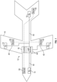
- FIG. 1 is a schematic illustration of an aircraft 10.
- the aircraft 10 includes a fire protection system 12 including one or more fire extinguishers 14.
- the fire extinguishers 14 may be arrayed around the aircraft 10 at selected locations. Further, while described herein in the context of an aircraft 10, one skilled in the art will readily appreciate that the fire protection system 12 described herein may be utilized in other applications, such as buildings, trucks, trains, or the like.
- the fire extinguishers 14 are operably connected to a controller 16 located in the aircraft 10.
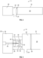
- the fire extinguisher 14 includes an extinguisher housing 18 or tank containing a volume of fire suppressant material 20.
- the fire extinguisher 14 includes a nozzle portion 22 having an extinguisher outlet 24 through which the fire suppressant material 20 is expelled from the fire extinguisher 14.
- a burst disk 26 or diaphragm is located in the extinguisher housing 18 and retains the fire suppressant material 20 until operation of the fire extinguisher 14 is initiated by rupturing of the burst disk 26.
- a firing cartridge 28 is operably connected to the fire extinguisher 14 such that when the firing cartridge 28 is activated the burst disk 26 is ruptured, and the fire suppressant material 20 flows from the extinguisher housing 18 and through the extinguisher outlet 24.
- the firing cartridge 28 including an ignition charge 30 and an output charge 32.
- the ignition charge 30 When the ignition charge 30 is activated, the ignition charge 30 ignites the output charge 32, which when activated ruptures the burst disk 26.
- a light signal 34 is utilized to activate the ignition charge 30
- the firing cartridge 28 includes a connector housing 36 connected to a cartridge housing 38, and includes an optical fiber 40 along which the light signal 34 is transmitted.
- the light signal 34 is transmitted through a lens 42 located between the optical fiber 40 and a bridge wire 44 extending across the ignition charge 30.
- the lens 42 is configured and positioned such that a lens focal point 46 is located at the bridge wire 44, such that the light signal 34 converges at the bridge wire 44 to heat the bridge wire 44 to the ignition temperature of the ignition charge 30.
- the ignition charge 30 is thus detonated initiating output charge 32 to puncture the burst disk 26 and release the fire suppressant material 20. While in the embodiment of FIG.
- a bridge wire 44 is utilized to ignite the ignition charge 30, in other embodiments the light signal 34 may be converged on other elements to heat the ignition charge 30, or the bridge wire 44 may be omitted and the light signal 34 may be converged directly onto the ignition charge 30 to heat and detonate the ignition charge 30.
- the light signal 34 is emitted from a light source 48, which in some embodiments is a laser, which is operably connected to the controller 16, which controls operation of the light source 48.
- a light source 48 which in some embodiments is a laser, which is operably connected to the controller 16, which controls operation of the light source 48.
- Each firing cartridge 28 connected to each fire extinguisher 14 is connected to the light source 48 via the optical fiber 40, which may include one or more branches extending from the light source 48 to each firing cartridge 28.
- one or more sensors 50 are located in the aircraft 10 to detect a fire or smoke condition and are operably connected to the light source 48 via the controller 16. When a sensor 50 detects a fire or smoke condition, the light source 48 is activated to initiate activation of one or more fire extinguishers 14 via the respective firing cartridge 28. In some embodiments, all of the fire extinguishers 14 may be activated, or fire extinguishers 14 may be selectively activated based on a location of the sensor 50 detecting a fire
- Fiber optic activation of the fire extinguishers 14 is immune to electrostatic discharge and lightning disruption, and also immune to electromagnetic interference and are unaffected by moisture or gas ingress. Further, optical fibers 40 have a low loss relative to the fiber length, and small size and weight. Further, optical fibers 40 may be utilized safely in environments characterized by hazardous materials and have high sensitivity and have a high degree of long term reliability.
Landscapes
- Health & Medical Sciences (AREA)
- Public Health (AREA)
- Business, Economics & Management (AREA)
- Emergency Management (AREA)
- Fire-Extinguishing By Fire Departments, And Fire-Extinguishing Equipment And Control Thereof (AREA)
- Fire-Detection Mechanisms (AREA)
Abstract
Description
- Exemplary embodiments pertain to the art of fire protection systems, and in particular to firing mechanisms for fire extinguishers of fire protection systems.
- In fire protection systems, such as those used in aircraft, fire extinguishers utilize electrical firing cartridges to puncture a burst disk in the fire extinguisher, resulting in the release of extinguishing agent from the fire extinguisher.
- In such systems, an electrical pulse is generated and transmitted to the firing cartridge to activate the fire extinguisher. A relatively high current, in some instances 3.5 amps for a pulse duration of 10 to 50 milliseconds is used to activate the firing cartridge. The electrical pulse is transmitted to a bridge wire in communication with an ignition charge, and the bridge wire initiates explosion of the ignition charge by heating the ignition charge to its ignition temperature.
- The electrical firing cartridge, however, is prone to issues such as electrostatic discharge and bridge wire corrosion. A high current firing circuit must be designed and installed in a location remote from the firing cartridge and high current electrical conductors are routed from the circuit to each of the fire extinguishers. Such systems are subject to losses and noise which much be accounted for.
- According to a first aspect of the invention, a fire protection system includes a fire extinguisher including a housing. The housing includes an extinguisher outlet and a burst disk. The burst disk configured to retain a volume of fire suppressant material in the housing. A firing cartridge is operably connected to the housing. The firing cartridge includes an output charge, and an ignition charge that, when detonated, causes release of the output charge to rupture the burst disk and release the volume of fire suppressant material through the extinguisher outlet. An optical fiber is configured to transmit a light signal toward the ignition charge to heat and detonate the ignition charge. A light source is operably connected to the optical fiber to transmit the light signal along the optical fiber.
- Additionally or alternatively, in this or other embodiments a bridge wire is located between the optical fiber and the ignition charge. The light signal is configured to heat the bridge wire to detonate the ignition charge.
- Additionally or alternatively, in this or other embodiments a lens is located between the optical fiber and the bridge wire. The lens is configured to converge the light signal at the bridge wire to heat the bridge wire.
- Additionally or alternatively, in this or other embodiments the light source is a laser.
- Additionally or alternatively, in this or other embodiments two or more fire extinguishers are operably connected to the light source.
- Additionally or alternatively, in this or other embodiments a sensor is operably connected to the light source. The sensor is configured to detect a fire or smoke condition to initiate operation of the light source.
- According to an aspect of the invention, a method of operating a fire protection system includes providing a fire extinguisher at a selected location. The fire extinguisher includes a housing, the housing includes an extinguisher outlet, and a burst disk. The burst disk is configured to retain the volume of fire suppressant material in the housing. A firing cartridge is operably connected to the housing. The firing cartridge includes an output charge and an ignition charge that, when detonated, causes release of the output charge to rupture the burst disk and release the volume of fire suppressant material through the extinguisher outlet. A light signal is transmitted from a light source along an optical fiber toward the ignition charge, and the ignition charge is heated via the light signal, thereby detonating the ignition charge.
- Additionally or alternatively, in this or other embodiments a bridge wire located between the optical fiber and the ignition charge is heated via the light signal, wherein heating of the bridge wire detonates the ignition charge.
- Additionally or alternatively, in this or other embodiments the light signal is transmitted through a lens located between the optical fiber and the bridge wire. The lens is configured to converge the light signal at the bridge wire to heat the bridge wire.
- Additionally or alternatively, in this or other embodiments the light source is a laser.
- Additionally or alternatively, in this or other embodiments two or more fire extinguishers are operably connected to the light source.
- Additionally or alternatively, in this or other embodiments a smoke or fire condition is detected via a sensor operably connected to the light source, and operation of the light source is initiated when the smoke or fire condition is detected.
- According to an aspect of the invention, an aircraft includes an aircraft structure, and a fire protection system located in the aircraft structure. The fire protection system includes a fire extinguisher including a housing. The housing includes an extinguisher outlet and a burst disk. The burst disk is configured to retain a volume of fire suppressant material in the housing. A firing cartridge is operably connected to the housing. The firing cartridge includes an output charge, and an ignition charge that, when detonated, causes release of the output charge to rupture the burst disk and release the volume of fire suppressant material through the extinguisher outlet. An optical fiber is configured to transmit a light signal toward the ignition charge to heat and detonate the ignition charge, and a light source is operably connected to the optical fiber to transmit the light signal along the optical fiber.
- Additionally or alternatively, in this or other embodiments a bridge wire is located between the optical fiber and the ignition charge. The light signal is configured to heat the bridge wire to detonate the ignition charge.
- Additionally or alternatively, in this or other embodiments a lens is located between the optical fiber and the bridge wire. The lens is configured to converge the light signal at the bridge wire to heat the bridge wire.
- Additionally or alternatively, in this or other embodiments the light source is a laser.
- Additionally or alternatively, in this or other embodiments a sensor is operably connected to the light source. The sensor is configured to detect a fire or smoke condition to initiate operation of the light source.
- Additionally or alternatively, in this or other embodiments two or more fire extinguishers are operably connected to the light source.
- The following descriptions should not be considered limiting in any way. With reference to the accompanying drawings, like elements are numbered alike:
-
FIG. 1 is a schematic illustration of an embodiment of an aircraft, including a fire protection system; -
FIG. 2 is a schematic illustration of an embodiment of a fire extinguisher of a fire protection system; and -
FIG. 3 is a schematic illustration of an embodiment of a firing cartridge of a fire extinguisher. - A detailed description of one or more embodiments of the disclosed apparatus and method are presented herein by way of exemplification and not limitation with reference to the Figures.
-
FIG. 1 is a schematic illustration of anaircraft 10. Theaircraft 10 includes afire protection system 12 including one ormore fire extinguishers 14. Thefire extinguishers 14 may be arrayed around theaircraft 10 at selected locations. Further, while described herein in the context of anaircraft 10, one skilled in the art will readily appreciate that thefire protection system 12 described herein may be utilized in other applications, such as buildings, trucks, trains, or the like. Thefire extinguishers 14 are operably connected to acontroller 16 located in theaircraft 10. - Referring now to
FIG. 2 , illustrated is an embodiment of afire extinguisher 14. Thefire extinguisher 14 includes anextinguisher housing 18 or tank containing a volume offire suppressant material 20. Thefire extinguisher 14 includes anozzle portion 22 having anextinguisher outlet 24 through which thefire suppressant material 20 is expelled from thefire extinguisher 14. Aburst disk 26 or diaphragm is located in theextinguisher housing 18 and retains thefire suppressant material 20 until operation of thefire extinguisher 14 is initiated by rupturing of theburst disk 26. - A firing
cartridge 28 is operably connected to thefire extinguisher 14 such that when the firingcartridge 28 is activated theburst disk 26 is ruptured, and thefire suppressant material 20 flows from theextinguisher housing 18 and through theextinguisher outlet 24. - Referring now to
FIG. 3 , the firingcartridge 28 including anignition charge 30 and anoutput charge 32. When theignition charge 30 is activated, theignition charge 30 ignites theoutput charge 32, which when activated ruptures theburst disk 26. - In the present disclosure, a
light signal 34 is utilized to activate theignition charge 30 The firingcartridge 28 includes aconnector housing 36 connected to acartridge housing 38, and includes anoptical fiber 40 along which thelight signal 34 is transmitted. Thelight signal 34 is transmitted through alens 42 located between theoptical fiber 40 and abridge wire 44 extending across theignition charge 30. Thelens 42 is configured and positioned such that a lensfocal point 46 is located at thebridge wire 44, such that thelight signal 34 converges at thebridge wire 44 to heat thebridge wire 44 to the ignition temperature of theignition charge 30. Theignition charge 30 is thus detonated initiatingoutput charge 32 to puncture theburst disk 26 and release thefire suppressant material 20. While in the embodiment ofFIG. 3 abridge wire 44 is utilized to ignite theignition charge 30, in other embodiments thelight signal 34 may be converged on other elements to heat theignition charge 30, or thebridge wire 44 may be omitted and thelight signal 34 may be converged directly onto theignition charge 30 to heat and detonate theignition charge 30. - Referring again to
FIG. 1 , thelight signal 34 is emitted from alight source 48, which in some embodiments is a laser, which is operably connected to thecontroller 16, which controls operation of thelight source 48. Each firingcartridge 28 connected to eachfire extinguisher 14 is connected to thelight source 48 via theoptical fiber 40, which may include one or more branches extending from thelight source 48 to each firingcartridge 28. In some embodiments, one ormore sensors 50 are located in theaircraft 10 to detect a fire or smoke condition and are operably connected to thelight source 48 via thecontroller 16. When asensor 50 detects a fire or smoke condition, thelight source 48 is activated to initiate activation of one ormore fire extinguishers 14 via therespective firing cartridge 28. In some embodiments, all of thefire extinguishers 14 may be activated, orfire extinguishers 14 may be selectively activated based on a location of thesensor 50 detecting a fire or smoke condition. - Fiber optic activation of the
fire extinguishers 14 is immune to electrostatic discharge and lightning disruption, and also immune to electromagnetic interference and are unaffected by moisture or gas ingress. Further,optical fibers 40 have a low loss relative to the fiber length, and small size and weight. Further,optical fibers 40 may be utilized safely in environments characterized by hazardous materials and have high sensitivity and have a high degree of long term reliability. - The term "about" is intended to include the degree of error associated with measurement of the particular quantity based upon the equipment available at the time of filing the application.
- The terminology used herein is for the purpose of describing particular embodiments only and is not intended to be limiting of the present disclosure. As used herein, the singular forms "a", "an" and "the" are intended to include the plural forms as well, unless the context clearly indicates otherwise. It will be further understood that the terms "comprises" and/or "comprising," when used in this specification, specify the presence of stated features, integers, steps, operations, elements, and/or components, but do not preclude the presence or addition of one or more other features, integers, steps, operations, element components, and/or groups thereof.
- While the present disclosure has been described with reference to an exemplary embodiment or embodiments, it will be understood by those skilled in the art that various changes may be made and equivalents may be substituted for elements thereof without departing from the scope of the present disclosure. In addition, many modifications may be made to adapt a particular situation or material to the teachings of the present disclosure without departing from the essential scope thereof. Therefore, it is intended that the present disclosure not be limited to the particular embodiment disclosed as the best mode contemplated for carrying out this present disclosure, but that the present disclosure will include all embodiments falling within the scope of the claims.
Claims (13)
- A fire protection system (12), comprising:
a fire extinguisher (14) including:a housing (18), the housing (18) including:an extinguisher outlet (24); anda burst disk (26), the burst disk (26) configured to retain a volume of fire suppressant material (20) in the housing (18);a firing cartridge (28) operably connected to the housing (18), the firing cartridge (28) including:an output charge (32); andan ignition charge (30) that, when detonated, causes release of the output charge (32) to rupture the burst disk (26) and release the volume of fire suppressant material (20) through the extinguisher outlet (24);an optical fiber (40) configured to transmit a light signal (34) toward the ignition charge (30) to heat and detonate the ignition charge (30); anda light source (48) operably connected to the optical fiber (40) to transmit the light signal (34) along the optical fiber (40). - The fire protection system (12) of claim 1, further comprising a bridge wire (44) disposed between the optical fiber (40) and the ignition charge (30), the light signal (34) configured to heat the bridge wire (44) to detonate the ignition charge (30).
- The fire protection system (12) of claim 2, further comprising a lens (42) disposed between the optical fiber (40) and the bridge wire (44), the lens (42) configured to converge the light signal (34) at the bridge wire (44) to heat the bridge wire (44).
- The fire protection system (12) of any preceding claim, wherein the light source (48) is a laser.
- The fire protection system (12) of any preceding claim, wherein two or more fire extinguishers (14) are operably connected to the light source (48).
- The fire protection system (12) of any preceding claim, further comprising a sensor (50) operably connected to the light source (48), the sensor (50) configured to detect a fire or smoke condition to initiate operation of the light source (48).
- A method of operating a fire protection system (12), comprising:providing a fire extinguisher (14) at a selected location, the fire extinguisher (14) including:a housing (18), the housing (18) including:an extinguisher outlet (24); anda burst disk (26), the burst disk (26) configured to retain a volume of fire suppressant material (20) in the housing (18);a firing cartridge (28) operably connected to the housing, the firing cartridge (28) including:an output charge (32); andan ignition charge (30) that, when detonated, causes release of the output charge (32) to rupture the burst disk (26) and release the volume of fire suppressant material (20) through the extinguisher outlet (24);transmitting a light signal (34) from a light source (48) along an optical fiber (40) toward the ignition charge (30); andheating the ignition charge (30) via the light signal (34), thereby detonating the ignition charge (30).
- The method of claim 7, further comprising heating a bridge wire (44) disposed between the optical fiber (40) and the ignition charge (30) via the light signal (34), wherein heating of the bridge wire (44) detonates the ignition charge (30).
- The method of claim 8, further comprising transmitting the light signal (34) through a lens (42) disposed between the optical fiber (40) and the bridge wire (44), the lens (42) configured to converge the light signal (34) at the bridge wire (44) to heat the bridge wire (44).
- The method of any of claims 7 to 9, wherein the light source (48) is a laser.
- The method of any of claims 7 to 10, wherein two or more fire extinguishers (14) are operably connected to the light source (48).
- The method of any of claims 7 to 11, further comprising:detecting a smoke or fire condition via a sensor (50) operably connected to the light source (48); andinitiating operation of the light source (48) when the smoke or fire condition is detected.
- An aircraft (10) comprising:an aircraft structure; anda fire protection system (12) as claimed in any of claims 1 to 6, disposed in the aircraft structure.
Applications Claiming Priority (1)
| Application Number | Priority Date | Filing Date | Title |
|---|---|---|---|
| US17/675,168 US12157027B2 (en) | 2022-02-18 | 2022-02-18 | Optical firing cartridge for fire extinguisher |
Publications (2)
| Publication Number | Publication Date |
|---|---|
| EP4230269A1 true EP4230269A1 (en) | 2023-08-23 |
| EP4230269B1 EP4230269B1 (en) | 2025-08-06 |
Family
ID=85132702
Family Applications (1)
| Application Number | Title | Priority Date | Filing Date |
|---|---|---|---|
| EP23153819.0A Active EP4230269B1 (en) | 2022-02-18 | 2023-01-27 | Optical firing cartridge for fire extinguisher |
Country Status (2)
| Country | Link |
|---|---|
| US (1) | US12157027B2 (en) |
| EP (1) | EP4230269B1 (en) |
Cited By (1)
| Publication number | Priority date | Publication date | Assignee | Title |
|---|---|---|---|---|
| US20250229115A1 (en) * | 2024-01-16 | 2025-07-17 | Kidde Technologies Inc. | Integral outlet fire extinguisher assembly |
Families Citing this family (1)
| Publication number | Priority date | Publication date | Assignee | Title |
|---|---|---|---|---|
| US12594445B2 (en) * | 2022-02-18 | 2026-04-07 | Kidde Technologies, Inc. | Addressing optical firing cartridge using chromatic aberration |
Citations (4)
| Publication number | Priority date | Publication date | Assignee | Title |
|---|---|---|---|---|
| US3884307A (en) * | 1973-11-12 | 1975-05-20 | Robert A Williams | Fire extinguisher |
| US3915237A (en) * | 1974-07-11 | 1975-10-28 | Us Army | Rapid fire suppressant discharge |
| CN201213989Y (en) * | 2008-05-30 | 2009-04-01 | 湖南工业大学 | An automatic directional fire extinguisher |
| US20160136468A1 (en) * | 2013-06-16 | 2016-05-19 | Koso Technologies Ltd. | Throwable fire extinguisher |
Family Cites Families (4)
| Publication number | Priority date | Publication date | Assignee | Title |
|---|---|---|---|---|
| AU8148098A (en) | 1997-06-30 | 1999-01-19 | Ensign-Bickford Company, The | Laser-ignitable ignition composition and initiator devices and assemblies comprising the same |
| FR2888234B1 (en) | 2005-07-05 | 2008-05-02 | Saint Louis Inst | OPTICALLY DOPED ENERGETIC COMPOSITION |
| CN204612617U (en) | 2015-04-16 | 2015-09-02 | 陆伟 | One sends out laser detonator in directly-heated type wink |
| US12594445B2 (en) * | 2022-02-18 | 2026-04-07 | Kidde Technologies, Inc. | Addressing optical firing cartridge using chromatic aberration |
-
2022
- 2022-02-18 US US17/675,168 patent/US12157027B2/en active Active
-
2023
- 2023-01-27 EP EP23153819.0A patent/EP4230269B1/en active Active
Patent Citations (4)
| Publication number | Priority date | Publication date | Assignee | Title |
|---|---|---|---|---|
| US3884307A (en) * | 1973-11-12 | 1975-05-20 | Robert A Williams | Fire extinguisher |
| US3915237A (en) * | 1974-07-11 | 1975-10-28 | Us Army | Rapid fire suppressant discharge |
| CN201213989Y (en) * | 2008-05-30 | 2009-04-01 | 湖南工业大学 | An automatic directional fire extinguisher |
| US20160136468A1 (en) * | 2013-06-16 | 2016-05-19 | Koso Technologies Ltd. | Throwable fire extinguisher |
Cited By (1)
| Publication number | Priority date | Publication date | Assignee | Title |
|---|---|---|---|---|
| US20250229115A1 (en) * | 2024-01-16 | 2025-07-17 | Kidde Technologies Inc. | Integral outlet fire extinguisher assembly |
Also Published As
| Publication number | Publication date |
|---|---|
| US20230264058A1 (en) | 2023-08-24 |
| US12157027B2 (en) | 2024-12-03 |
| EP4230269B1 (en) | 2025-08-06 |
Similar Documents
| Publication | Publication Date | Title |
|---|---|---|
| EP4230269B1 (en) | Optical firing cartridge for fire extinguisher | |
| US5206455A (en) | Laser initiated ordnance systems | |
| EP4230268A1 (en) | Addressing optical firing cartridge using chromatic aberration | |
| US5155293A (en) | Safety booster for explosive systems | |
| US3915236A (en) | Safety device | |
| US20020196152A1 (en) | Automated fire protection system | |
| US4281718A (en) | Method of releasing a sprinkler, and a sprinkler head adapted to the method | |
| US5915480A (en) | Fire extinguishing system | |
| US2693240A (en) | Method and apparatus for preventing explosions and extinguishing fires | |
| US5101727A (en) | Electro-optical detonator | |
| US7654186B1 (en) | Fuze module | |
| ES3059643T3 (en) | Method and system for dispensing detection of a pyrotechnical countermeasure | |
| KR102323527B1 (en) | Apparatus and System for Fire Extinguisher by using Solid-Aerosol | |
| EP3329970A1 (en) | Safety system for fire suppressant distribution devices | |
| US8939082B2 (en) | Blasting arrangement | |
| CN105201542A (en) | Automatic powder spraying and explosion suppression device for ZYBG (A) gas pipeline conveying | |
| TR201701594A2 (en) | Automatic or manual detonation system of the firefighting ball with heat or electrical triggering | |
| CN209771175U (en) | High-rise remote control temperature control fire extinguishing device | |
| KR101328815B1 (en) | Bursting apparatus of glass bulb | |
| WO2007128203A1 (en) | Firework system with non-powder electronic ignition head | |
| KR101870362B1 (en) | Mock bomb with display function of drop point | |
| JPH08150225A (en) | Automatic fire extinguisher for aircraft | |
| CN223096037U (en) | Fire extinguishing bomb detonation system | |
| RU2407573C1 (en) | Fire extinguishing system | |
| CN223930580U (en) | An airborne digital precision time-delay control fire extinguishing bomb system |
Legal Events
| Date | Code | Title | Description |
|---|---|---|---|
| PUAI | Public reference made under article 153(3) epc to a published international application that has entered the european phase |
Free format text: ORIGINAL CODE: 0009012 |
|
| STAA | Information on the status of an ep patent application or granted ep patent |
Free format text: STATUS: THE APPLICATION HAS BEEN PUBLISHED |
|
| AK | Designated contracting states |
Kind code of ref document: A1 Designated state(s): AL AT BE BG CH CY CZ DE DK EE ES FI FR GB GR HR HU IE IS IT LI LT LU LV MC ME MK MT NL NO PL PT RO RS SE SI SK SM TR |
|
| STAA | Information on the status of an ep patent application or granted ep patent |
Free format text: STATUS: REQUEST FOR EXAMINATION WAS MADE |
|
| 17P | Request for examination filed |
Effective date: 20240215 |
|
| RBV | Designated contracting states (corrected) |
Designated state(s): AL AT BE BG CH CY CZ DE DK EE ES FI FR GB GR HR HU IE IS IT LI LT LU LV MC ME MK MT NL NO PL PT RO RS SE SI SK SM TR |
|
| GRAP | Despatch of communication of intention to grant a patent |
Free format text: ORIGINAL CODE: EPIDOSNIGR1 |
|
| STAA | Information on the status of an ep patent application or granted ep patent |
Free format text: STATUS: GRANT OF PATENT IS INTENDED |
|
| INTG | Intention to grant announced |
Effective date: 20240814 |
|
| GRAJ | Information related to disapproval of communication of intention to grant by the applicant or resumption of examination proceedings by the epo deleted |
Free format text: ORIGINAL CODE: EPIDOSDIGR1 |
|
| STAA | Information on the status of an ep patent application or granted ep patent |
Free format text: STATUS: REQUEST FOR EXAMINATION WAS MADE |
|
| INTC | Intention to grant announced (deleted) | ||
| GRAP | Despatch of communication of intention to grant a patent |
Free format text: ORIGINAL CODE: EPIDOSNIGR1 |
|
| STAA | Information on the status of an ep patent application or granted ep patent |
Free format text: STATUS: GRANT OF PATENT IS INTENDED |
|
| INTG | Intention to grant announced |
Effective date: 20250303 |
|
| GRAS | Grant fee paid |
Free format text: ORIGINAL CODE: EPIDOSNIGR3 |
|
| GRAA | (expected) grant |
Free format text: ORIGINAL CODE: 0009210 |
|
| STAA | Information on the status of an ep patent application or granted ep patent |
Free format text: STATUS: THE PATENT HAS BEEN GRANTED |
|
| AK | Designated contracting states |
Kind code of ref document: B1 Designated state(s): AL AT BE BG CH CY CZ DE DK EE ES FI FR GB GR HR HU IE IS IT LI LT LU LV MC ME MK MT NL NO PL PT RO RS SE SI SK SM TR |
|
| REG | Reference to a national code |
Ref country code: GB Ref legal event code: FG4D |
|
| REG | Reference to a national code |
Ref country code: CH Ref legal event code: EP |
|
| REG | Reference to a national code |
Ref country code: DE Ref legal event code: R096 Ref document number: 602023005303 Country of ref document: DE |
|
| REG | Reference to a national code |
Ref country code: IE Ref legal event code: FG4D |
|
| REG | Reference to a national code |
Ref country code: NL Ref legal event code: MP Effective date: 20250806 |
|
| PG25 | Lapsed in a contracting state [announced via postgrant information from national office to epo] |
Ref country code: IS Free format text: LAPSE BECAUSE OF FAILURE TO SUBMIT A TRANSLATION OF THE DESCRIPTION OR TO PAY THE FEE WITHIN THE PRESCRIBED TIME-LIMIT Effective date: 20251206 |
|
| PG25 | Lapsed in a contracting state [announced via postgrant information from national office to epo] |
Ref country code: NO Free format text: LAPSE BECAUSE OF FAILURE TO SUBMIT A TRANSLATION OF THE DESCRIPTION OR TO PAY THE FEE WITHIN THE PRESCRIBED TIME-LIMIT Effective date: 20251106 |
|
| REG | Reference to a national code |
Ref country code: LT Ref legal event code: MG9D |
|
| PG25 | Lapsed in a contracting state [announced via postgrant information from national office to epo] |
Ref country code: PT Free format text: LAPSE BECAUSE OF FAILURE TO SUBMIT A TRANSLATION OF THE DESCRIPTION OR TO PAY THE FEE WITHIN THE PRESCRIBED TIME-LIMIT Effective date: 20251209 |
|
| PG25 | Lapsed in a contracting state [announced via postgrant information from national office to epo] |
Ref country code: FI Free format text: LAPSE BECAUSE OF FAILURE TO SUBMIT A TRANSLATION OF THE DESCRIPTION OR TO PAY THE FEE WITHIN THE PRESCRIBED TIME-LIMIT Effective date: 20250806 |
|
| PG25 | Lapsed in a contracting state [announced via postgrant information from national office to epo] |
Ref country code: HR Free format text: LAPSE BECAUSE OF FAILURE TO SUBMIT A TRANSLATION OF THE DESCRIPTION OR TO PAY THE FEE WITHIN THE PRESCRIBED TIME-LIMIT Effective date: 20250806 Ref country code: NL Free format text: LAPSE BECAUSE OF FAILURE TO SUBMIT A TRANSLATION OF THE DESCRIPTION OR TO PAY THE FEE WITHIN THE PRESCRIBED TIME-LIMIT Effective date: 20250806 |
|
| PGFP | Annual fee paid to national office [announced via postgrant information from national office to epo] |
Ref country code: FR Payment date: 20251217 Year of fee payment: 4 |
|
| PG25 | Lapsed in a contracting state [announced via postgrant information from national office to epo] |
Ref country code: GR Free format text: LAPSE BECAUSE OF FAILURE TO SUBMIT A TRANSLATION OF THE DESCRIPTION OR TO PAY THE FEE WITHIN THE PRESCRIBED TIME-LIMIT Effective date: 20251107 |
|
| PG25 | Lapsed in a contracting state [announced via postgrant information from national office to epo] |
Ref country code: SE Free format text: LAPSE BECAUSE OF FAILURE TO SUBMIT A TRANSLATION OF THE DESCRIPTION OR TO PAY THE FEE WITHIN THE PRESCRIBED TIME-LIMIT Effective date: 20250806 |
|
| PG25 | Lapsed in a contracting state [announced via postgrant information from national office to epo] |
Ref country code: LV Free format text: LAPSE BECAUSE OF FAILURE TO SUBMIT A TRANSLATION OF THE DESCRIPTION OR TO PAY THE FEE WITHIN THE PRESCRIBED TIME-LIMIT Effective date: 20250806 |
|
| PG25 | Lapsed in a contracting state [announced via postgrant information from national office to epo] |
Ref country code: BG Free format text: LAPSE BECAUSE OF FAILURE TO SUBMIT A TRANSLATION OF THE DESCRIPTION OR TO PAY THE FEE WITHIN THE PRESCRIBED TIME-LIMIT Effective date: 20250806 Ref country code: PL Free format text: LAPSE BECAUSE OF FAILURE TO SUBMIT A TRANSLATION OF THE DESCRIPTION OR TO PAY THE FEE WITHIN THE PRESCRIBED TIME-LIMIT Effective date: 20250806 |
|
| PG25 | Lapsed in a contracting state [announced via postgrant information from national office to epo] |
Ref country code: RS Free format text: LAPSE BECAUSE OF FAILURE TO SUBMIT A TRANSLATION OF THE DESCRIPTION OR TO PAY THE FEE WITHIN THE PRESCRIBED TIME-LIMIT Effective date: 20251106 |
|
| PG25 | Lapsed in a contracting state [announced via postgrant information from national office to epo] |
Ref country code: ES Free format text: LAPSE BECAUSE OF FAILURE TO SUBMIT A TRANSLATION OF THE DESCRIPTION OR TO PAY THE FEE WITHIN THE PRESCRIBED TIME-LIMIT Effective date: 20250806 |
|
| REG | Reference to a national code |
Ref country code: AT Ref legal event code: MK05 Ref document number: 1821138 Country of ref document: AT Kind code of ref document: T Effective date: 20250806 |
|
| PG25 | Lapsed in a contracting state [announced via postgrant information from national office to epo] |
Ref country code: SM Free format text: LAPSE BECAUSE OF FAILURE TO SUBMIT A TRANSLATION OF THE DESCRIPTION OR TO PAY THE FEE WITHIN THE PRESCRIBED TIME-LIMIT Effective date: 20250806 |
|
| PG25 | Lapsed in a contracting state [announced via postgrant information from national office to epo] |
Ref country code: DK Free format text: LAPSE BECAUSE OF FAILURE TO SUBMIT A TRANSLATION OF THE DESCRIPTION OR TO PAY THE FEE WITHIN THE PRESCRIBED TIME-LIMIT Effective date: 20250806 |
|
| PGFP | Annual fee paid to national office [announced via postgrant information from national office to epo] |
Ref country code: DE Payment date: 20251217 Year of fee payment: 4 |
|
| PG25 | Lapsed in a contracting state [announced via postgrant information from national office to epo] |
Ref country code: AT Free format text: LAPSE BECAUSE OF FAILURE TO SUBMIT A TRANSLATION OF THE DESCRIPTION OR TO PAY THE FEE WITHIN THE PRESCRIBED TIME-LIMIT Effective date: 20250806 |
|
| PG25 | Lapsed in a contracting state [announced via postgrant information from national office to epo] |
Ref country code: IT Free format text: LAPSE BECAUSE OF FAILURE TO SUBMIT A TRANSLATION OF THE DESCRIPTION OR TO PAY THE FEE WITHIN THE PRESCRIBED TIME-LIMIT Effective date: 20250806 |
|
| PG25 | Lapsed in a contracting state [announced via postgrant information from national office to epo] |
Ref country code: CZ Free format text: LAPSE BECAUSE OF FAILURE TO SUBMIT A TRANSLATION OF THE DESCRIPTION OR TO PAY THE FEE WITHIN THE PRESCRIBED TIME-LIMIT Effective date: 20250806 |
|
| PG25 | Lapsed in a contracting state [announced via postgrant information from national office to epo] |
Ref country code: EE Free format text: LAPSE BECAUSE OF FAILURE TO SUBMIT A TRANSLATION OF THE DESCRIPTION OR TO PAY THE FEE WITHIN THE PRESCRIBED TIME-LIMIT Effective date: 20250806 Ref country code: SK Free format text: LAPSE BECAUSE OF FAILURE TO SUBMIT A TRANSLATION OF THE DESCRIPTION OR TO PAY THE FEE WITHIN THE PRESCRIBED TIME-LIMIT Effective date: 20250806 |
|
| REG | Reference to a national code |
Ref country code: DE Ref legal event code: R097 Ref document number: 602023005303 Country of ref document: DE |
|
| PLBE | No opposition filed within time limit |
Free format text: ORIGINAL CODE: 0009261 |
|
| STAA | Information on the status of an ep patent application or granted ep patent |
Free format text: STATUS: NO OPPOSITION FILED WITHIN TIME LIMIT |
|
| REG | Reference to a national code |
Ref country code: CH Ref legal event code: L10 Free format text: ST27 STATUS EVENT CODE: U-0-0-L10-L00 (AS PROVIDED BY THE NATIONAL OFFICE) Effective date: 20260617 |
|
| PG25 | Lapsed in a contracting state [announced via postgrant information from national office to epo] |
Ref country code: LT Free format text: LAPSE BECAUSE OF FAILURE TO SUBMIT A TRANSLATION OF THE DESCRIPTION OR TO PAY THE FEE WITHIN THE PRESCRIBED TIME-LIMIT Effective date: 20250806 |
|
| 26N | No opposition filed |
Effective date: 20260507 |