EP4230146A1 - Wiederverwendungsverhinderung einer intraluminalen vorrichtung mit patientenschnittstellenmodul und zugehörige vorrichtungen, systeme und verfahren - Google Patents
Wiederverwendungsverhinderung einer intraluminalen vorrichtung mit patientenschnittstellenmodul und zugehörige vorrichtungen, systeme und verfahren Download PDFInfo
- Publication number
- EP4230146A1 EP4230146A1 EP23175062.1A EP23175062A EP4230146A1 EP 4230146 A1 EP4230146 A1 EP 4230146A1 EP 23175062 A EP23175062 A EP 23175062A EP 4230146 A1 EP4230146 A1 EP 4230146A1
- Authority
- EP
- European Patent Office
- Prior art keywords
- voltage
- memory
- pim
- intraluminal
- sensing device
- Prior art date
- Legal status (The legal status is an assumption and is not a legal conclusion. Google has not performed a legal analysis and makes no representation as to the accuracy of the status listed.)
- Pending
Links
Images

Classifications
-
- G—PHYSICS
- G06—COMPUTING OR CALCULATING; COUNTING
- G06F—ELECTRIC DIGITAL DATA PROCESSING
- G06F3/00—Input arrangements for transferring data to be processed into a form capable of being handled by the computer; Output arrangements for transferring data from processing unit to output unit, e.g. interface arrangements
- G06F3/06—Digital input from, or digital output to, record carriers, e.g. RAID, emulated record carriers or networked record carriers
- G06F3/0601—Interfaces specially adapted for storage systems
- G06F3/0602—Interfaces specially adapted for storage systems specifically adapted to achieve a particular effect
- G06F3/062—Securing storage systems
- G06F3/0622—Securing storage systems in relation to access
-
- A—HUMAN NECESSITIES
- A61—MEDICAL OR VETERINARY SCIENCE; HYGIENE
- A61B—DIAGNOSIS; SURGERY; IDENTIFICATION
- A61B8/00—Diagnosis using ultrasonic, sonic or infrasonic waves
- A61B8/56—Details of data transmission or power supply
-
- A—HUMAN NECESSITIES
- A61—MEDICAL OR VETERINARY SCIENCE; HYGIENE
- A61B—DIAGNOSIS; SURGERY; IDENTIFICATION
- A61B5/00—Measuring for diagnostic purposes; Identification of persons
- A61B5/15—Devices for taking samples of blood
- A61B5/150007—Details
- A61B5/150885—Preventing re-use
-
- A—HUMAN NECESSITIES
- A61—MEDICAL OR VETERINARY SCIENCE; HYGIENE
- A61B—DIAGNOSIS; SURGERY; IDENTIFICATION
- A61B5/00—Measuring for diagnostic purposes; Identification of persons
- A61B5/15—Devices for taking samples of blood
- A61B5/151—Devices specially adapted for taking samples of capillary blood, e.g. by lancets, needles or blades
- A61B5/15142—Devices intended for single use, i.e. disposable
-
- A—HUMAN NECESSITIES
- A61—MEDICAL OR VETERINARY SCIENCE; HYGIENE
- A61B—DIAGNOSIS; SURGERY; IDENTIFICATION
- A61B8/00—Diagnosis using ultrasonic, sonic or infrasonic waves
- A61B8/12—Diagnosis using ultrasonic, sonic or infrasonic waves in body cavities or body tracts, e.g. by using catheters
-
- G—PHYSICS
- G06—COMPUTING OR CALCULATING; COUNTING
- G06F—ELECTRIC DIGITAL DATA PROCESSING
- G06F3/00—Input arrangements for transferring data to be processed into a form capable of being handled by the computer; Output arrangements for transferring data from processing unit to output unit, e.g. interface arrangements
- G06F3/06—Digital input from, or digital output to, record carriers, e.g. RAID, emulated record carriers or networked record carriers
- G06F3/0601—Interfaces specially adapted for storage systems
- G06F3/0628—Interfaces specially adapted for storage systems making use of a particular technique
- G06F3/0646—Horizontal data movement in storage systems, i.e. moving data in between storage devices or systems
- G06F3/0652—Erasing, e.g. deleting, data cleaning, moving of data to a wastebasket
-
- G—PHYSICS
- G06—COMPUTING OR CALCULATING; COUNTING
- G06F—ELECTRIC DIGITAL DATA PROCESSING
- G06F3/00—Input arrangements for transferring data to be processed into a form capable of being handled by the computer; Output arrangements for transferring data from processing unit to output unit, e.g. interface arrangements
- G06F3/06—Digital input from, or digital output to, record carriers, e.g. RAID, emulated record carriers or networked record carriers
- G06F3/0601—Interfaces specially adapted for storage systems
- G06F3/0628—Interfaces specially adapted for storage systems making use of a particular technique
- G06F3/0655—Vertical data movement, i.e. input-output transfer; data movement between one or more hosts and one or more storage devices
- G06F3/0659—Command handling arrangements, e.g. command buffers, queues, command scheduling
-
- G—PHYSICS
- G06—COMPUTING OR CALCULATING; COUNTING
- G06F—ELECTRIC DIGITAL DATA PROCESSING
- G06F3/00—Input arrangements for transferring data to be processed into a form capable of being handled by the computer; Output arrangements for transferring data from processing unit to output unit, e.g. interface arrangements
- G06F3/06—Digital input from, or digital output to, record carriers, e.g. RAID, emulated record carriers or networked record carriers
- G06F3/0601—Interfaces specially adapted for storage systems
- G06F3/0668—Interfaces specially adapted for storage systems adopting a particular infrastructure
- G06F3/0671—In-line storage system
- G06F3/0673—Single storage device
- G06F3/0679—Non-volatile semiconductor memory device, e.g. flash memory, one time programmable memory [OTP]
-
- A—HUMAN NECESSITIES
- A61—MEDICAL OR VETERINARY SCIENCE; HYGIENE
- A61B—DIAGNOSIS; SURGERY; IDENTIFICATION
- A61B17/00—Surgical instruments, devices or methods
- A61B2017/0023—Surgical instruments, devices or methods disposable
-
- A—HUMAN NECESSITIES
- A61—MEDICAL OR VETERINARY SCIENCE; HYGIENE
- A61B—DIAGNOSIS; SURGERY; IDENTIFICATION
- A61B90/00—Instruments, implements or accessories specially adapted for surgery or diagnosis and not covered by any of the groups A61B1/00 - A61B50/00, e.g. for luxation treatment or for protecting wound edges
- A61B90/08—Accessories or related features not otherwise provided for
- A61B2090/0803—Counting the number of times an instrument is used
-
- A—HUMAN NECESSITIES
- A61—MEDICAL OR VETERINARY SCIENCE; HYGIENE
- A61B—DIAGNOSIS; SURGERY; IDENTIFICATION
- A61B90/00—Instruments, implements or accessories specially adapted for surgery or diagnosis and not covered by any of the groups A61B1/00 - A61B50/00, e.g. for luxation treatment or for protecting wound edges
- A61B90/08—Accessories or related features not otherwise provided for
- A61B2090/0814—Preventing re-use
-
- A—HUMAN NECESSITIES
- A61—MEDICAL OR VETERINARY SCIENCE; HYGIENE
- A61B—DIAGNOSIS; SURGERY; IDENTIFICATION
- A61B2560/00—Constructional details of operational features of apparatus; Accessories for medical measuring apparatus
- A61B2560/04—Constructional details of apparatus
- A61B2560/0475—Special features of memory means, e.g. removable memory cards
-
- A—HUMAN NECESSITIES
- A61—MEDICAL OR VETERINARY SCIENCE; HYGIENE
- A61B—DIAGNOSIS; SURGERY; IDENTIFICATION
- A61B8/00—Diagnosis using ultrasonic, sonic or infrasonic waves
- A61B8/08—Clinical applications
- A61B8/0891—Clinical applications for diagnosis of blood vessels
-
- B—PERFORMING OPERATIONS; TRANSPORTING
- B06—GENERATING OR TRANSMITTING MECHANICAL VIBRATIONS IN GENERAL
- B06B—METHODS OR APPARATUS FOR GENERATING OR TRANSMITTING MECHANICAL VIBRATIONS OF INFRASONIC, SONIC, OR ULTRASONIC FREQUENCY, e.g. FOR PERFORMING MECHANICAL WORK IN GENERAL
- B06B1/00—Methods or apparatus for generating mechanical vibrations of infrasonic, sonic, or ultrasonic frequency
- B06B1/02—Methods or apparatus for generating mechanical vibrations of infrasonic, sonic, or ultrasonic frequency making use of electrical energy
- B06B1/0207—Driving circuits
-
- B—PERFORMING OPERATIONS; TRANSPORTING
- B06—GENERATING OR TRANSMITTING MECHANICAL VIBRATIONS IN GENERAL
- B06B—METHODS OR APPARATUS FOR GENERATING OR TRANSMITTING MECHANICAL VIBRATIONS OF INFRASONIC, SONIC, OR ULTRASONIC FREQUENCY, e.g. FOR PERFORMING MECHANICAL WORK IN GENERAL
- B06B2201/00—Indexing scheme associated with B06B1/0207 for details covered by B06B1/0207 but not provided for in any of its subgroups
- B06B2201/70—Specific application
- B06B2201/76—Medical, dental
Definitions
- the present disclosure relates generally relates to disabling subsequent use of a disposable, single-use intraluminal sensing device with at patient interface module (PIM).
- the intraluminal sensing device can include a memory, and the PIM can write to the memory to disable further operation of the intraluminal sensing device after it has been used in a clinical procedure.
- Intravascular devices such as guide wires, catheters, guide catheters, etc.
- Such intravascular devices are generally disposable devices.
- a manufacturer generally rates the intravascular device for a single use. That is, the manufacturer guarantees the safety of the intravascular device and/or the integrity of the data collected using the intravascular device for a single use. After being used within the vasculature of a patient in a clinical procedure, the intravascular device is discarded.
- Embodiments of the present disclosure provide a way to prevent authorized reuse of a single use intraluminal device, such as an intravascular catheter or guidewire.
- a patient interface module (PIM) is communicatively positioned between a console/processing system and an intraluminal device.
- the intraluminal device includes a memory.
- the PIM is able to selectively transmit read commands at a first signal voltage and write commands at a second signal voltage to the memory of the intraluminal device.
- the PIM selectively outputs the first voltage or the second voltage using a voltage switch including a plurality of electronic components, such as transistors.
- the present disclosure is directed to an intraluminal sensing system.
- the system includes a patient interface module (PIM) communicatively disposed between a processing system and an intraluminal sensing device configured to obtain physiology data associated with a body lumen of a patient while positioned within the body lumen, the intraluminal sensing device comprising a memory, wherein the patient interface module comprises: a controller operable to: read data stored on the memory of the intraluminal sensing device using a first signal voltage; and write to the memory to disable further operation of the intraluminal sensing device using a second signal voltage; and a voltage switch configured to selectively output the first signal voltage or the second signal voltage.
- PIM patient interface module
- the voltage switch comprises a plurality of electronic components.
- the plurality of electronic components comprises a plurality of transistors.
- the plurality of transistors comprises a plurality of metal-oxide-semiconductor field-effect transistors (MOSFETs).
- MOSFETs metal-oxide-semiconductor field-effect transistors
- the plurality of MOSFETs comprises a p-channel MOSFET and a plurality of n-channel MOSFETs.
- the second signal voltage is associated with a command to erase the memory.
- the second signal voltage is associated with a command to write a date stamp to the memory.
- the date stamp is representative of a use date of the intraluminal sensing device to obtain the physiology data.
- the memory comprises an EEPROM.
- the system further includes the intraluminal sensing device; and the processing system.
- the present disclosure is directed to a method of preventing unauthorized use of an intraluminal sensing device.
- the method includes reading, using a controller of a patient interface module (PIM) communicatively disposed between a processing system and an intraluminal sensing device configured to obtain physiology data associated with a body lumen of a patient while positioned within the body lumen, data stored on a memory of the intraluminal sensing device using a first signal voltage; and modifying a voltage of an output signal using a voltage switch of the PIM; and writing to the memory to disable further operation of the intraluminal sensing device using a second signal voltage.
- PIM patient interface module
- the voltage switch comprises a plurality of electronic components.
- the plurality of electronic components comprises a plurality of transistors.
- the plurality of transistors comprises a plurality of metal-oxide-semiconductor field-effect transistors (MOSFETs).
- MOSFETs metal-oxide-semiconductor field-effect transistors
- the plurality of MOSFETs comprises a p-channel MOSFET and a plurality of n-channel MOSFETs.
- the writing to the memory comprises transmitting a command to erase the memory.
- the writing to the memory comprises transmitting a command to write a date stamp to the memory.
- the date stamp is representative of a use date of the intraluminal sensing device to obtain the physiology data.
- the memory comprises an EEPROM.
- the devices, systems, and methods described herein relate to a patient interface module (PIM) having the ability to read and write to a memory of a disposable catheter or guide wire, preventing the reuse of that device.
- PIM patient interface module
- An aspect of the present disclosure includes reading and/or writing to the EEPROM via a bidirectional bit stream set by changing the pull-up voltage through the use of MOSFET switching. This selectively transmits the required "read” voltage or the "write” voltage to the EEPROM.
- the reuse prevention architecture using a read and write capability advantageously prevents reuse of the intraluminal device and/or access to the sensitive material stored on the memory of the intraluminal device by a third party.
- the general architecture for reuse prevention design includes a microprocessor or FPGA (host) capable of programming the EEPROM using a single bidirectional signal line to communicate the "read" and "write” commands by either the same voltage or different voltages.
- the read voltage can be set at the host side by an n-channel MOSFET.
- the write voltage is set by a p-channel MOSFET.
- Selectively outputting the read voltage or the write voltage is controlled by voltage switch, including one or more n-channel MOSFETs and one or more p-channel MOSFETs.
- the read voltage or the write voltage is set by the MOSFETs switching "gate" pin.
- the host controls the output data communication set voltage depending on the EEPROM's characteristic of a "read” or "write” command.
- the host can set an operational time stamp for use, erase the EEPROM preventing access to and/or removing proprietary catheter data, e.g., as an option to avoid quick catheter disconnect.
- creating a time stamp on the disposable intraluminal device based on a command by a processor of the PIM, and sending a write command by the serial bit stream advantageously creates an actual disposable device after the device has been use in a medical procedure.
- the devices, systems, and methods of the present disclosure advantageously facilitate patient safety by preventing unauthorized reuse of intraluminal devices which that are not rated from multiple uses. Also, financial losses to the manufacturer of the single-use intraluminal device are advantageously reduced.
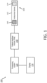
- Fig. 1 is a diagrammatic schematic view of an intraluminal system 100, according to aspects of the present disclosure.
- the intraluminal system 100 includes an intraluminal device 110, a processing system 120, a display 130, and a patient interface module (PIM) 140.
- PIM patient interface module
- the intraluminal device 110 can include a flexible elongate member 112, a sensor 114 disposed at the distal portion of the flexible elongate member 112, and a memory 116 disposed at the proximal portion of the flexible elongate member 112.
- the intraluminal device can be a catheter, a guide wire, and/or a guide catheter.
- the intraluminal device 110 can be size and shaped, structurally arranged, and/or otherwise configured to be positioned within anatomy, such as a body lumen, of a patient.
- the anatomy may represent any fluid-filled or surrounded structures, both natural and man-made.
- the anatomy can be within the body of a patient. Fluid can flow through the lumen of the anatomy.
- the anatomy can be a vessel, such as a blood vessel, in which blood flows through the lumen of the vessel.
- the intraluminal device can be an intravascular device and the intraluminal system can be an intravascular system.
- the blood vessel is an artery or a vein of a patient's vascular system, including cardiac vasculature, peripheral vasculature, neural vasculature, renal vasculature, and/or any other suitable anatomy/lumen inside the body.
- the anatomy can be tortuous in some instances.
- the device 110 may be used to examine any number of anatomical locations and tissue types, including without limitation, organs including the liver, heart, kidneys, gall bladder, pancreas, lungs, esophagus; ducts; intestines; nervous system structures including the brain, dural sac, spinal cord and peripheral nerves; the urinary tract; as well as valves within the blood, chambers or other parts of the heart, and/or other systems of the body.
- the device 110 may be used to examine man-made structures such as, but without limitation, heart valves, stents, shunts, filters and other devices.
- the intraluminal device 110 is configured to image the body lumen of a patient (e.g., a lumen of a blood vessel) using one or more imaging modalities.
- the sensing component 114 can be an imaging component.
- the sensor 114 is an ultrasound transducer and/or an ultrasound transducer array.
- the intraluminal device 110 can be an intravascular ultrasound or IVUS imaging device.
- the intraluminal device can be a rotational IVUS imaging device including a rotating drive cable that rotates one or more ultrasound transducers at the distal portion of the flexible elongate member 112.
- the intraluminal device can be a phased array IVUS imaging device including a circumferential/annular transducer array around a longitudinal axis.
- the sensor 114 can obtain imaging data associated with intravascular ultrasound (IVUS) imaging, forward-looking intravascular ultrasound (FL-IVUS) imaging, intravascular photoacoustic (IVPA) imaging, intracardiac echocardiography (ICE), forward-looking intracardiac echocardiography (FLICE), transesophageal echocardiography (TEE), and/or other suitable imaging modalities.
- the device 110 can include an imaging component of any suitable imaging modality, such as optical imaging, optical coherence tomography (OCT), etc.
- the device 110 can include any suitable sensing component 114, including a pressure sensor, a flow sensor, a temperature sensor, an optical fiber, a reflector, a mirror, a prism, an ablation element, a radio frequency (RF) electrode, a conductor, and/or combinations thereof.
- the intraluminal device 110 can include one or more sensing components 114.
- the sensor 114 can be an electronic component, an optical component, an acoustic component, and/or combinations thereof.
- the intraluminal device 110 includes a memory 116.
- the memory 116 can be a rewritable/reprogrammable memory that can be rewritten or reprogrammed, after being initially programmed during manufacturing of the intraluminal device 110, without degradation of the memory and/or the intraluminal device 110.
- the memory 116 can include one or more bits that determine whether the memory 116 can be read and/or accessed. For example, in response to command signal associated with the memory 116, and received from the processing system 120 and/or the PIM 140, the ability to read and/or access the memory 116 can be disabled, which prevents subsequent operation of the intraluminal device 110.
- a command signal from the processing system 120 and/or the PIM 140 can erase the memory 116.
- the processing system 120 and/or the PIM 140 can write a use date to the memory 116. The use date can be read by any suitable processing system and/or PIM upon subsequent use of the intraluminal device 110, which disallows operation of the intraluminal device 110.
- the memory 116 can be Electrically Erasable Programmable Read-Only Memory (EEPROM), flash memory, hard disk, RFID, and/or other suitable storage.
- EEPROM Electrically Erasable Programmable Read-Only Memory
- the storage capacity of the memory 116 can be 0.5 KB, 1 KB, 2 KB, and/or other suitable values, both larger and smaller.
- the memory 116 can be disposed on a proximal connector of the intraluminal device 110, as described in U.S. Patent No. 9,101,298 , titled "Apparatus and Method for Use of RFID Catheter Intelligence," the entirety of which is hereby incorporated by reference herein.
- the memory 116 has sufficient capacity to store data about the intraluminal device 110, such as a parameters associated with the sensing component 114 and/or the intraluminal device 110.
- the memory 116 can be store data related to the catheter type, serial number, configuration for sensitivity, channel matching, ringdown parameters, catheter over-current indicator, and ramp-gain-control (RGC), selection for control of the timing voltage for the PIM's variable-gain-amplifier (VGA), etc.
- the data stored on memory 116 can be sensitive and/or proprietary information that a manufacturer of the intraluminal device 110 would not want a third party or competitor to access. As described herein, access to the memory 116 by a third party or competitor is advantageously prevented.
- the intraluminal device 110 is a disposable or limited use device.
- a manufacturer can guarantee the safety of the intraluminal device 110 and/or the integrity of the data collected using the intraluminal device 110 for a single use, in some embodiments.
- unauthorized reuse e.g., subsequent use after a first use of the intraluminal device 110 to obtain intraluminal data
- the intraluminal device 110 can be used in multiple procedures, after the manufacturer or authorized third-party has sterilized and/or reconditioned the intraluminal device 110, as described in U.S. Patent No. 9,445,723 , titled "Devices, Systems and Methods for Authenticated Intravascular Device Use and Reuse," the entirety of which is hereby incorporated by reference herein.
- the system 100 includes a processing system or console 120 that is in communication with the intraluminal device 110 via the PIM 140.
- the computing device 120 can include a processing circuit, such as one or more processors in communication with a memory.
- the computing device 120 can control the intraluminal device 110 and/or the PIM 140 to obtain medical data associated with the anatomy in which the intraluminal device 110 is positioned.
- the system 100 can include an input device, such as a keyboard, mouse, controller with buttons, touchscreen, touchpad, etc., in communication with the computer 120.
- the computer 120 can output command signals to the PIM 140 and/or the intraluminal device 110 to, e.g., start/stop acquisition of the intraluminal data.
- the processing system 120 and/or the PIM 140 transmits a signal to read the memory 116 of the intraluminal device 110.
- the intraluminal device 110 can transmit data stored on the memory 116, such as the identity of the device 110, the sensor type of the sensor 114, etc., to the PIM 140 and/or the processing system 120.
- the intraluminal device 110 and/or the PIM 140 can transmit data signals to the processing system 120.
- electrical signals representative of the physiology data obtained by the sensing component 114 can be transmitted from the intraluminal device 110 to the processing system 120 via the PIM 140.
- the processing system 120 can be configured to process the received data, generate a visual representation of the obtained data, and output the visual representation of the obtained data to the display 130.
- the input device, the display 130, and/or the processing system 120 can be separate components. In other embodiments, one or more of the input device, the display 130, and/or the processing system 120 can be combined or be a single component.
- the system includes the PIM 140 communicatively positioned between the processing system 120 and the intraluminal device 110.
- the PIM 140 is configured to write to the memory 116 to prevent unauthorized reuse of the intraluminal device 110.
- the PIM 140 facilitates communication of signals between the console 120 and the intraluminal device 110.
- the PIM 140 supplies high- and/or low-voltage DC power to support operation of the intravascular device 110, including the component(s) 114 for imaging, pressure measurement, and/or flow measurement.
- the PIM 140 is configured to access, read, and/or write the memory 116 based on, e.g., instructions from the processing system 120.
- the processing system 120 is configured to directly access, read, and/or write the memory 116 without the PIM 140.
- the PIM 140 can comprise a housing having any suitable shape.
- the PIM 140 can include a volume (e.g., a length, a width, a depth, a radius, etc.) within the housing configured to accommodate one or more components described herein.
- the PIM 140 can be sized and shaped, structurally arranged, and/or otherwise configured for handheld use in some embodiments.
- the PIM 140 can include features similar to those described in U.S. Patent Application No. 62/574455, titled “DIGITAL ROTATIONAL PATIENT INTERFACE MODULE,” filed Oct. 19, 2017 , U.S. Patent Application No. 62/574655, titled “WIRELESS DIGITAL PATIENT INTERFACE MODULE USING WIRELESS CHARGING,” filed Oct. 19, 2017 , U.S. Patent Application No. 62/574835, titled “INTRALUMINAL MEDICAL SYSTEM WITH OVERLOADED CONNECTORS,” filed Oct. 20, 2017 , and U.S. Patent Application No.
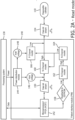
- Figs. 2A , 2B , 3A , and 3B illustrate additional aspects of the system 100 and/or the PIM 140.
- Figs. 2A and 2B are diagrammatic schematic views of the intraluminal sensing system 100, including the patient interface module 140.
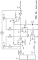
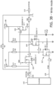
- Figs. 3A and 3B are electrical circuit diagrams of the PIM 140.
- Figs. 2A and 3A illustrate the system 100 and/or the PIM 140 in a read mode.
- Figs. 2B and 3B illustrate the system 100 and/or the PIM 140 in a write mode.
- the processing system 120 transmits power to a power distribution module 144 of the PIM 140.
- the power distribution module 144 distributes power received from the processing system 120 to various components of the PIM 140 (e.g., a processor 142, a transmitter associated with an ultrasound transducer of the intraluminal device 110, etc.).
- the power transmitted by the processing system 120 has a voltage, such as 5V, 10V, 12V, 15V, 20V, 40V, and/or other suitable value, both larger and smaller, for example.
- the power distribution module 144 is configured to distribute power to the various components of the PIM 140 at various voltages, which may be the same or different than the voltage transmitted by the processing system 120 to the PIM 140.
- the host voltage 146 and/or the read/write voltage 148 can be the same or different than the voltage transmitted by the processing system 120 to the PIM 140.
- the host voltage 146 can be the same or different than the read/write voltage 148.
- the host voltage 146 and/or the read/write voltage 148 can be 1V, 2V, 3V, 5V, 10V, 12V, 15V, and/or other suitable value, both larger and smaller.
- the PIM 140 includes a processing component 142.
- the processing component 142 can be a microprocessor. In some embodiments, the processing component 142 is a field programmable gate (FPGA).
- the processing component 142 can be referenced as a host in some instances.
- the processing component 142 can be one or more processors configured to receive electrical signals representative of data from and/or transmit electrical signals representative of data to the processing system 120 and/or the intraluminal device 110.
- the processor or controller 142 can transmit data bit stream 150, 154 to the intraluminal device 110 to, e.g., read or write to the memory 116.
- the data bit stream 150, 154 can be an electrical signal that includes an amplitude or voltage, frequency, timing, sequence, and/or other characteristics.
- Read signals from the PIM 140 to the memory 116 can be a first signal voltage
- write signals from the PIM 140 to the memory 116 can be a second signal voltage.
- the first and second signal voltages are the same. In some embodiments, the first and second signal voltages are different.
- the PIM 140 includes a voltage or power switch.
- the voltage or power switch can include one or more electronic components, such as one or more metal-oxide-semiconductor field-effect transistors (MOSFETs).
- MOSFETs metal-oxide-semiconductor field-effect transistors
- the voltage or power switch can be electrically disposed between the processor 142 and the output of the PIM 140 such that the voltage or power switch selectively determines the voltage of the output signal from the PIM 140 to the intraluminal device 110. In that regard, the voltage or power switch determines whether output voltage of the PIM 140 should be host voltage 146 and/or the output voltage of the processor 142, or whether the output voltage of the PIM 140 should be the read/write voltage 148.
- exemplary electrical signals associated with the data bit streams 150, 154 are shown in Figs. 2A , 2B , 3A , and 3B .
- the amplitude or voltage of the exemplary electrical signal is same for both the data bit stream 150 output by the processor 142 and the data bit stream 154 that is output from the PIM 140 to the intraluminal device 110.
- Figs. 2A and 3A illustrate a read mode in which the data bit streams 150, 154 allow the processor 142 to read the memory 116, for example, in response to a command from the processing system 120.
- the voltage of the data bit streams 150, 154 of Figs. 2A and 3A is the host voltage 146.
- the host voltage 146 and the voltage of the data bit streams 150, 154 of Figs. 2A and 3A is 3V.
- the voltage or power switch of the PIM 140 is configured to determine and/or to change the output signal voltage of the PIM 140.
- the amplitude or voltage of the exemplary electrical signal associated with the data bit stream 150 output by the processor 142 is different than the amplitude or voltage of the exemplary electrical signal associated with the data bit stream 154 that is output from the PIM 140 to the intraluminal device 110.
- Figs. 2B and 3B illustrate a write mode in which the data bit streams 150, 154 allow the processor 142 to write to the memory 116, for example, in response to a command from the processing system 120.
- the processing system 120 and/or the processor 142 can write one or more bits to the memory 116 to lock, and/or otherwise disallow further reading of the memory 116.
- the processing system 120 and/or the processor 142 can write one or more bits to the memory 116 to erase the memory 116.
- the processing system 120 and/or the processor 142 can write one or more bits to the memory 116 associated with a time stamp, e.g., representative of the use of the intraluminal device 110.
- the voltage of the data bit stream 150 is the host voltage 146, while, in Figs. 2B and 3B , the voltage of the data bit stream 154 is the read/write voltage 148.
- the voltage or power switch of the PIM 140 is disposed between the processor 142 and the output of the PIM 140 such that the voltage or power switch selectively determines the voltage of the output signal from the PIM 140.
- the host voltage 146 and/or the voltage the data bit stream 150 can be 3V
- the read/write voltage 148 and/or the voltage of the data bit stream 154 is 12V in in Figs. 2B and 3B .
- the voltage or power switch modifies only the amplitude or voltage of the electrical signal output.
- the frequency, timing, sequence, and/or other characteristics of the electrical signal remain the same between the signal output by the processor 142 and the PIM 140.
- the voltage or power switch of the PIM 140 can include one or more electronic components 160, 162, 164, 166.
- the electronic components 160, 162, 164, 166 can be one or more transistors.
- the transistors can be a bipolar junction transistor (BJT), a field-effect transistor (FET), other suitable transistor type, and/or combinations thereof.
- the transistor can be a p-channel transistor or an n-channel transistor.
- the electronic components 160, 162, 164, 166 can be one or more junction field effect transistors (JFETs) or metal-oxide-semiconductor field-effect transistors (MOSFETs).
- the transistor can be a depletion-mode and enhancement-mode transistor.
- the voltage or power switch of the PIM 140 can include one, two, three, four, five, or more electronic components 160, 162, 164, 166.
- the PIM 140 includes four MOSFETs, including three n-channel MOSFETs 160, 162, 164 and one p-channel MOSFET 166.
- the PIM 140 can include an even or odd number of MOSFETs, including an one or more n-channel MOSFETs (e.g., an even or odd number) and one or more p-channel MOSFETs (e.g., an even of odd number).
- MOSFETs including an one or more n-channel MOSFETs (e.g., an even or odd number) and one or more p-channel MOSFETs (e.g., an even of odd number).
- the MOSFETs 160, 162, 164, 166 are arranged in communication with one another, the processor 142, and/or the memory 116 of the intraluminal device 110 such that the PIM 140 outputs the host voltage 146 (e.g., 3V) or the read/write voltage 148 (e.g., 12V) to the memory 116 of the intraluminal device 110.
- the n-channel MOSFET 160 is electrically and/or communicatively disposed between the processor 142 and the memory 116.
- the n-channel MOSFET 162 is electrically and/or communicatively disposed between the processor 142 and n-channel MOSFET 164.
- the n-channel MOSFET 164 is electrically and/or communicatively disposed between the n-channel MOSFET 162, n-channel MOSFET 160, and the p-channel MOSFET 166.
- the processor 142 transmits the data bit stream 150 including one or more bits that are representative of the command to the memory 116 and/or the intraluminal device 110.
- the voltage or power switch determines the output signal voltage of the PIM 140, which is represented by data bit stream 154.
- the processor 142 transmits a read/write signal 158 to the n-channel MOSFET 162.
- the read/write signal 158 can be transmitted by the processor in response to a signal to do from the processing system 120.
- the read/write signal 158 can be one or more bits indicating whether the PIM will read the memory 116 or write to the memory 116.
- the read/write signal 158 can be a single bit, such as a 1 (high) or 0 (low).
- the read/write signal 158 is low.
- the low read/write signal 158 is the input of the n-channel MOSFET 162.
- N-channel MOSFETs invert the signal from low to high or high to low. Accordingly, the output signal of the n-channel MOSFET 162 and the input signal of the n-channel MOSFET 164 is high.
- the output signal of the n-channel MOSFET 164 is low. Accordingly, the input signal of the n-channel MOSFET 160 and the input signal of the p-channel MOSFET is low.
- P-channel MOSFETs maintain, rather than invert, the signal such that a high signal is maintained as high and a low signal is maintained as low.
- the output signal of the p-channel MOSFET 166 is low.
- the output signal of the n-channel MOSFET 160 is high.
- the n-channel MOSFET 160 is in communication with the host voltage 146 such that when the output of the n-channel MOSFET 160 is high, the data bit stream 154 has the host voltage 146.
- the host voltage 146 will be present on the memory 116.
- the signal on pin 2 of n-channel MOSFET 160 goes low, the data will go from n-channel MOSFET 160 pin 1 to pin 6.
- the p-channel MOSFET is in communication with read/write voltage 148 such that when the output of the p-channel MOSFET is low, the data bit stream 154 does not have the read/write voltage 148 (e.g., 12V). As shown in Fig. 3A , when the input signal of the p-channel MOSFET 166 is low, the read/write voltage 148 (e.g., 12V) is not transmitted across p-channel MOSFET 166 to the memory 116.
- the read/write signal 158 is high.
- the high read/write signal 158 is the input of the n-channel MOSFET 162. Accordingly, the output signal of the n-channel MOSFET 162 and the input signal of the n-channel MOSFET 164 is low.
- the output signal of the n-channel MOSFET 164 is high.
- the input signal of the n-channel MOSFET 160 and the input signal of the p-channel MOSFET is high. Therefore, the output signal of the p-channel MOSFET 166 is high.
- the output signal of the n-channel MOSFET 160 is low.
- the p-channel MOSFET is in communication with read/write voltage 148 such that when the output of the p-channel MOSFET is high, the data bit stream 154 has the read/write voltage 148 (e.g., 12V).
- the read/write voltage 148 e.g., 12V
- the read/write voltage 148 is transmitted across p-channel MOSFET 166 using pins 1 and 6 to the memory 116.
- the signal on the gate pin on the p-channel MOSFET 166 determines if the output signal of the PIM 140 is the read/write voltage 148 or the host voltage 146, from the n-channel MOSFET 160.
- the n-channel MOSFET 160 is in communication with the host voltage 146 such that when the output of the n-channel MOSFET 160 is low, the data bit stream 154 does not have the host voltage 146.
- the read/write voltage 148 will be present on the memory 116. As shown in Fig. 3B , this causes the host voltage 146 and data to go from n-channel MOSFET pin 1 to pin 2, and then to p-channel MOSFET 166 pin 2 to pin 6. This creates a write to the EEPROM.
- the input signal and/or output signal of the n-channel MOSFET 164, the n-channel MOSFET 160, and/or the p-channel MOSFET 166 can determine the output signal voltage of the PIM 140 (e.g., the data bit stream 154) in some embodiments.
- the PIM 140 and/or the voltage switch of the PIM 140 can include one or more electronic components, such as one or more resistors and/or capacitors in communication with the MOSFETs 160, 162, 164, 166, the host voltage 146, and/or the read/write voltage 148.
- the n-channel MOSFET 160 is communicatively arranged to prevent the read/write voltage 148 from being transmitted to the processor 142.
- the processor 142 is configured to only operate at the host voltage 146, in some embodiments.
- the n-channel MOSFET 160 advantageously isolates the processor 142 from the read/write voltage 148, which can be transmitted to the intraluminal device 110.
- Fig. 4 provides a flow diagram illustrating a method 400 of preventing unauthorized use of an intraluminal sensing device.
- the method 400 includes a number of enumerated steps, but embodiments of the method 400 may include additional steps before, after, and in between the enumerated steps. In some embodiments, one or more of the enumerated steps may be omitted, performed in a different order, or performed concurrently.
- the method 400 may be performed using one or more of the systems and devices referred to in Figs. 1 , 2A , 2B , 3A , and 3B .
- the method 400 includes determining an intraluminal sensing device is connected to the patient interface module (PIM).
- the intraluminal sensing device can include a memory, such as an EEPROM, and sensing component configured to obtain intraluminal sensing data associated with anatomy in which the intraluminal sensing device is positioned.
- the method 400 includes reading, using a controller or processor of the PIM, data on the memory of the intraluminal sensing device.
- the controller can read the data using a first signal voltage.
- Step 420 can be performed by a console/processing system and/or the PIM, e.g., in response a command signal from the console/processing system.
- the PIM can be communicatively interposed between the console and the intraluminal sensing device.
- the method 400 includes controlling the sensing device to obtain the intraluminal sensing data.
- a control signal at the first voltage can be transmitted from the PIM to sensing component of the intraluminal device.
- Step 430 can be performed by a console/processing system and/or the PIM, e.g., in response a command signal from the console/processing system.
- the method 400 includes modifying the voltage of the output signal using a voltage or power switch of the PIM.
- the voltage switch can include a plurality of electronic components, such as a plurality of transistors.
- the voltage switch can be configured to selectively output the first voltage or a second voltage from the PIM to the intraluminal sensing device.
- Step 440 can be performed by a console/processing system and/or the PIM, e.g., in response a command signal from the console/processing system.
- a controller or processor of the PIM can transmit a command such that the voltage switch selectively determines whether the PIM outputs the first signal voltage or the second signal voltage.
- the method 400 includes writing to the memory of the intraluminal sensing device to disable further operation using the second signal voltage.
- the memory of the intraluminal sensing device can be written to lock out or prevent further access to the memory.
- the step 450 erases the memory.
- the step 450 writes a date and/or time stamp, e.g., indicative of a use date and/or time of the intraluminal device.
- the step 450 writes any suitable data indicative of the usage of the intraluminal device.
- the data written to the memory can be read by a console/processing system and/or a PIM as a day, month, year.
- the data written to the memory can be a manufacturing lot unit built.
- a console/processing system and/or a PIM can recognize the manufacturing lot and disallow use when intraluminal devices associated with that manufacturing lot are beyond the period rated for use.
- Another example is writing the console/system's serial number with date code (e.g., use date), preventing the intraluminal device from use by another system.
- Step 440 can be performed by a console/processing system and/or the PIM, e.g., in response a command signal from the console/processing system.
- the console/processing can transmit a command to the PIM to prevent further access to the memory of the intraluminal device using any suitable parameter.
- the console can command the PIM to write to the memory to disable access, e.g., after a specified period of time (e.g., 10 minutes, 30 minutes, 60 minutes, 120 minutes, and/or other suitable values, both larger and smaller) post-commencement of a sensing procedure, post-completion of the sensing procedure, in response to a user input to end the collection of sensing data, when the sensing component 114 moves in a low power mode, prior to the intraluminal device 110 being unplugged, etc.
- a specified period of time e.g., 10 minutes, 30 minutes, 60 minutes, 120 minutes, and/or other suitable values, both larger and smaller
- the method 400 includes disallow operation of intraluminal sensing device when subsequent use is attempted.
- a console or a PIM in a subsequent use attempt cannot read the memory of the intraluminal device because read access has been locked and/or the memory has been erased.
- the console or the PIM read the date stamp or other indication of use stored on the memory.
- the console and/or the PIM disallows subsequent operation of the intraluminal sensing device.
- the system disclosed herein is well suited to authentication of any disposable or single use device, such as interventional devices for diagnosis or treatment (e.g. interventional needles, biopsy devices).
- interventional devices e.g. interventional needles, biopsy devices.
- the interventional devices substitute the intraluminal sensing devices in the system and method disclosed herein for the alternative embodiments.
- interventional devices substitute the intraluminal sensing devices in the system and method disclosed herein for the alternative embodiments.
- One skilled in the art will recognize the application of the principles herein across other disciplines.
Landscapes
- Engineering & Computer Science (AREA)
- Health & Medical Sciences (AREA)
- Life Sciences & Earth Sciences (AREA)
- Physics & Mathematics (AREA)
- Theoretical Computer Science (AREA)
- Animal Behavior & Ethology (AREA)
- Pathology (AREA)
- Biomedical Technology (AREA)
- Heart & Thoracic Surgery (AREA)
- Medical Informatics (AREA)
- Molecular Biology (AREA)
- Surgery (AREA)
- Biophysics (AREA)
- General Health & Medical Sciences (AREA)
- Public Health (AREA)
- Veterinary Medicine (AREA)
- Human Computer Interaction (AREA)
- General Engineering & Computer Science (AREA)
- General Physics & Mathematics (AREA)
- Nuclear Medicine, Radiotherapy & Molecular Imaging (AREA)
- Radiology & Medical Imaging (AREA)
- Computer Networks & Wireless Communication (AREA)
- Hematology (AREA)
- Infusion, Injection, And Reservoir Apparatuses (AREA)
- Endoscopes (AREA)
- Ultra Sonic Daignosis Equipment (AREA)
Applications Claiming Priority (3)
| Application Number | Priority Date | Filing Date | Title |
|---|---|---|---|
| US201762574687P | 2017-10-19 | 2017-10-19 | |
| EP18793191.0A EP3697310B1 (de) | 2017-10-19 | 2018-10-17 | Wiederverwendungsverhinderung einer intraluminalen vorrichtung mit patientenschnittstellenmodul und zugehörige vorrichtungen, systeme und verfahren |
| PCT/EP2018/078381 WO2019076971A1 (en) | 2017-10-19 | 2018-10-17 | PREVENTING THE REUSE OF AN INTRALUMINAL DEVICE WITH PATIENT INTERFACE MODULE AND DEVICES, SYSTEMS, AND RELATED METHODS |
Related Parent Applications (2)
| Application Number | Title | Priority Date | Filing Date |
|---|---|---|---|
| EP18793191.0A Division-Into EP3697310B1 (de) | 2017-10-19 | 2018-10-17 | Wiederverwendungsverhinderung einer intraluminalen vorrichtung mit patientenschnittstellenmodul und zugehörige vorrichtungen, systeme und verfahren |
| EP18793191.0A Division EP3697310B1 (de) | 2017-10-19 | 2018-10-17 | Wiederverwendungsverhinderung einer intraluminalen vorrichtung mit patientenschnittstellenmodul und zugehörige vorrichtungen, systeme und verfahren |
Publications (1)
| Publication Number | Publication Date |
|---|---|
| EP4230146A1 true EP4230146A1 (de) | 2023-08-23 |
Family
ID=63998692
Family Applications (2)
| Application Number | Title | Priority Date | Filing Date |
|---|---|---|---|
| EP18793191.0A Active EP3697310B1 (de) | 2017-10-19 | 2018-10-17 | Wiederverwendungsverhinderung einer intraluminalen vorrichtung mit patientenschnittstellenmodul und zugehörige vorrichtungen, systeme und verfahren |
| EP23175062.1A Pending EP4230146A1 (de) | 2017-10-19 | 2018-10-17 | Wiederverwendungsverhinderung einer intraluminalen vorrichtung mit patientenschnittstellenmodul und zugehörige vorrichtungen, systeme und verfahren |
Family Applications Before (1)
| Application Number | Title | Priority Date | Filing Date |
|---|---|---|---|
| EP18793191.0A Active EP3697310B1 (de) | 2017-10-19 | 2018-10-17 | Wiederverwendungsverhinderung einer intraluminalen vorrichtung mit patientenschnittstellenmodul und zugehörige vorrichtungen, systeme und verfahren |
Country Status (5)
| Country | Link |
|---|---|
| US (2) | US11733881B2 (de) |
| EP (2) | EP3697310B1 (de) |
| JP (1) | JP6782388B1 (de) |
| CN (1) | CN111225616A (de) |
| WO (1) | WO2019076971A1 (de) |
Cited By (8)
| Publication number | Priority date | Publication date | Assignee | Title |
|---|---|---|---|---|
| US11813484B2 (en) | 2018-11-28 | 2023-11-14 | Histosonics, Inc. | Histotripsy systems and methods |
| US11813485B2 (en) | 2020-01-28 | 2023-11-14 | The Regents Of The University Of Michigan | Systems and methods for histotripsy immunosensitization |
| US12318636B2 (en) | 2022-10-28 | 2025-06-03 | Histosonics, Inc. | Histotripsy systems and methods |
| US12343568B2 (en) | 2020-08-27 | 2025-07-01 | The Regents Of The University Of Michigan | Ultrasound transducer with transmit-receive capability for histotripsy |
| US12446905B2 (en) | 2023-04-20 | 2025-10-21 | Histosonics, Inc. | Histotripsy systems and associated methods including user interfaces and workflows for treatment planning and therapy |
| US12527976B2 (en) | 2020-06-18 | 2026-01-20 | Histosonics, Inc. | Histotripsy acoustic and patient coupling systems and methods |
| US12582848B2 (en) | 2021-06-07 | 2026-03-24 | The Regents Of The University Of Michigan | Minimally invasive histotripsy systems and methods |
| US12599787B2 (en) | 2021-06-07 | 2026-04-14 | The Regents Of The University Of Michigan | All-in-one ultrasound systems and methods including histotripsy |
Families Citing this family (2)
| Publication number | Priority date | Publication date | Assignee | Title |
|---|---|---|---|---|
| WO2019174984A1 (en) | 2018-03-15 | 2019-09-19 | Koninklijke Philips N.V. | Variable intraluminal ultrasound transmit pulse generation and control devices, systems, and methods |
| JP7527360B2 (ja) * | 2019-10-08 | 2024-08-02 | コーニンクレッカ フィリップス エヌ ヴェ | 使用追跡を伴う使い捨て腔内感知デバイス |
Citations (4)
| Publication number | Priority date | Publication date | Assignee | Title |
|---|---|---|---|---|
| US20060161054A1 (en) * | 1999-04-14 | 2006-07-20 | Reuss James L | Limited use medical probe |
| US20070083111A1 (en) * | 2005-10-12 | 2007-04-12 | Volcano Corporation | Apparatus and method for use of RFID catheter intelligence |
| US20130103023A1 (en) * | 2011-10-24 | 2013-04-25 | Ethicon Endo-Surgery, Inc. | Litz wire battery powered device |
| US9445723B2 (en) | 2014-04-09 | 2016-09-20 | Koninklijke Philips N.V. | Devices, systems and methods for authenticated intravascular device use and reuse |
Family Cites Families (16)
| Publication number | Priority date | Publication date | Assignee | Title |
|---|---|---|---|---|
| US7089427B1 (en) * | 2000-11-28 | 2006-08-08 | Nintendo Co., Ltd. | Security system method and apparatus for preventing application program unauthorized use |
| AU2003298638A1 (en) * | 2002-11-12 | 2004-06-03 | Prourocare, Inc. | Intelligent medical device barrier |
| JP2006024012A (ja) * | 2004-07-08 | 2006-01-26 | Fujitsu Ltd | 非接触ic記録媒体、記録媒体管理プログラムおよび記録媒体管理方法 |
| AU2005291952A1 (en) * | 2004-09-30 | 2006-04-13 | Boston Scientific Limited | Adapter for use with digital imaging medical device |
| US7864606B2 (en) * | 2007-09-18 | 2011-01-04 | Spansion Israel Ltd | Method, device and system for regulating access to an integrated circuit (IC) device |
| JP5188880B2 (ja) * | 2008-05-26 | 2013-04-24 | オリンパスメディカルシステムズ株式会社 | カプセル型医療装置およびカプセル型医療装置の充電方法 |
| JP2011104004A (ja) * | 2009-11-13 | 2011-06-02 | Hoya Corp | 内視鏡スコープおよび内視鏡装置 |
| JP2011177430A (ja) * | 2010-03-03 | 2011-09-15 | Terumo Corp | 医療用マニピュレータシステム |
| US10426320B2 (en) * | 2010-04-28 | 2019-10-01 | Xiaolong OuYang | Single use medical devices |
| CA2896499A1 (en) * | 2012-12-27 | 2014-07-03 | Volcano Corporation | Fire control system for rotational ivus |
| US9757200B2 (en) * | 2013-03-14 | 2017-09-12 | The Spectranetics Corporation | Intelligent catheter |
| US9414812B2 (en) * | 2013-05-14 | 2016-08-16 | Acist Medical Systems, Inc. | System and method for monitoring device engagement |
| EP3134135B1 (de) * | 2014-04-22 | 2018-06-06 | Medtronic Ardian Luxembourg S.à.r.l. | Anti-resterilisationskomponenten für katheterbehandlungsvorrichtungen sowie zugehörige vorrichtungen, systeme und verfahren |
| WO2019076698A1 (en) | 2017-10-19 | 2019-04-25 | Koninklijke Philips N.V. | PORTABLE MEDICAL INTERFACE FOR INTRALUMINAL DEVICE AND ASSOCIATED DEVICES, SYSTEMS, AND METHODS |
| WO2019076968A1 (en) | 2017-10-19 | 2019-04-25 | Koninklijke Philips N.V. | DIGITAL ROTARY PATIENT INTERFACE MODULE |
| WO2019077141A1 (en) | 2017-10-20 | 2019-04-25 | Koninklijke Philips N.V. | INTRALUMINAL MEDICAL SYSTEM WITH MULTI-DEVICE CONNECTORS |
-
2018
- 2018-10-17 EP EP18793191.0A patent/EP3697310B1/de active Active
- 2018-10-17 US US16/756,354 patent/US11733881B2/en active Active
- 2018-10-17 EP EP23175062.1A patent/EP4230146A1/de active Pending
- 2018-10-17 WO PCT/EP2018/078381 patent/WO2019076971A1/en not_active Ceased
- 2018-10-17 CN CN201880067767.2A patent/CN111225616A/zh active Pending
- 2018-10-17 JP JP2020520616A patent/JP6782388B1/ja active Active
-
2023
- 2023-08-21 US US18/236,015 patent/US20230393764A1/en active Pending
Patent Citations (5)
| Publication number | Priority date | Publication date | Assignee | Title |
|---|---|---|---|---|
| US20060161054A1 (en) * | 1999-04-14 | 2006-07-20 | Reuss James L | Limited use medical probe |
| US20070083111A1 (en) * | 2005-10-12 | 2007-04-12 | Volcano Corporation | Apparatus and method for use of RFID catheter intelligence |
| US9101298B2 (en) | 2005-10-12 | 2015-08-11 | Volcano Corporation | Apparatus and method for use of RFID catheter intelligence |
| US20130103023A1 (en) * | 2011-10-24 | 2013-04-25 | Ethicon Endo-Surgery, Inc. | Litz wire battery powered device |
| US9445723B2 (en) | 2014-04-09 | 2016-09-20 | Koninklijke Philips N.V. | Devices, systems and methods for authenticated intravascular device use and reuse |
Cited By (15)
| Publication number | Priority date | Publication date | Assignee | Title |
|---|---|---|---|---|
| US12491384B2 (en) | 2018-11-28 | 2025-12-09 | Histosonics, Inc. | Histotripsy systems and methods |
| US11813484B2 (en) | 2018-11-28 | 2023-11-14 | Histosonics, Inc. | Histotripsy systems and methods |
| US11980778B2 (en) | 2018-11-28 | 2024-05-14 | Histosonics, Inc. | Histotripsy systems and methods |
| US12599784B2 (en) | 2018-11-28 | 2026-04-14 | Histosonics, Inc. | Histotripsy systems and methods |
| US12491382B2 (en) | 2018-11-28 | 2025-12-09 | Histosonics, Inc. | Histotripsy systems and methods |
| US12589261B2 (en) | 2018-11-28 | 2026-03-31 | Histosonics, Inc. | Histotripsy systems and methods |
| US12420118B2 (en) | 2018-11-28 | 2025-09-23 | Histosonics, Inc. | Histotripsy systems and methods |
| US11813485B2 (en) | 2020-01-28 | 2023-11-14 | The Regents Of The University Of Michigan | Systems and methods for histotripsy immunosensitization |
| US12527976B2 (en) | 2020-06-18 | 2026-01-20 | Histosonics, Inc. | Histotripsy acoustic and patient coupling systems and methods |
| US12343568B2 (en) | 2020-08-27 | 2025-07-01 | The Regents Of The University Of Michigan | Ultrasound transducer with transmit-receive capability for histotripsy |
| US12582848B2 (en) | 2021-06-07 | 2026-03-24 | The Regents Of The University Of Michigan | Minimally invasive histotripsy systems and methods |
| US12599787B2 (en) | 2021-06-07 | 2026-04-14 | The Regents Of The University Of Michigan | All-in-one ultrasound systems and methods including histotripsy |
| US12390665B1 (en) | 2022-10-28 | 2025-08-19 | Histosonics, Inc. | Histotripsy systems and methods |
| US12318636B2 (en) | 2022-10-28 | 2025-06-03 | Histosonics, Inc. | Histotripsy systems and methods |
| US12446905B2 (en) | 2023-04-20 | 2025-10-21 | Histosonics, Inc. | Histotripsy systems and associated methods including user interfaces and workflows for treatment planning and therapy |
Also Published As
| Publication number | Publication date |
|---|---|
| US20200333965A1 (en) | 2020-10-22 |
| JP2020536680A (ja) | 2020-12-17 |
| EP3697310B1 (de) | 2023-06-28 |
| US20230393764A1 (en) | 2023-12-07 |
| US11733881B2 (en) | 2023-08-22 |
| EP3697310A1 (de) | 2020-08-26 |
| WO2019076971A1 (en) | 2019-04-25 |
| CN111225616A (zh) | 2020-06-02 |
| JP6782388B1 (ja) | 2020-11-11 |
Similar Documents
| Publication | Publication Date | Title |
|---|---|---|
| US20230393764A1 (en) | Intraluminal device reuse prevention with patient interface module and associated devices, systems, and methods | |
| US12390194B2 (en) | Point-of-care guidance system for diagnostic and therapeutic medical procedures | |
| US11520874B2 (en) | Self-authenticating intravascular device and associated devices, systems, and methods | |
| CN220275624U (zh) | 超声系统及其智能附件 | |
| US12599405B2 (en) | Intraosseous device including a sensing obturator | |
| US20240341732A1 (en) | Intraluminal medical system with overloaded connectors | |
| US10912624B2 (en) | System and apparatus for sensing contact on a robotic mechanism in a catheter procedure system | |
| Osoegawa et al. | Improved techniques for double-balloon-enteroscopy-assisted endoscopic retrograde cholangiopancreatography | |
| US12349983B2 (en) | Systems and methods for ultrasound-and-bioimpedance-based guidance of medical devices | |
| US20220355100A1 (en) | Electrode locating systems and methods for use during a cochlear implant lead insertion procedure | |
| US20250160786A1 (en) | Intravascular ultrasound imaging with contour generation and editing for circular and non-circular blood vessel borders | |
| CN114469254A (zh) | 用于超声分解内腔内凝块的医疗系统 | |
| EP4041089B1 (de) | Wegwerfbare intraluminale sensorvorrichtung mit benutzungsverfolgung | |
| US12582379B2 (en) | Ultrasound-equipped catheter stylet system | |
| CN109700530B (zh) | 用于耳鼻喉(ent)工具的位置跟踪启用连接器 | |
| WO2025061490A1 (en) | Shape memory sensor sheath for intraluminal device, associated devices, systems and methods | |
| Sousa | Design of an endovascular morcellator for the surgical treatment of equine Cushing's disease | |
| CN117679632A (zh) | 一种用于保证血泵信息的方法、设备 | |
| Valente | Handheld Ultrasound Guidance for Percutaneous Nephrolithotomy |
Legal Events
| Date | Code | Title | Description |
|---|---|---|---|
| PUAI | Public reference made under article 153(3) epc to a published international application that has entered the european phase |
Free format text: ORIGINAL CODE: 0009012 |
|
| STAA | Information on the status of an ep patent application or granted ep patent |
Free format text: STATUS: THE APPLICATION HAS BEEN PUBLISHED |
|
| AC | Divisional application: reference to earlier application |
Ref document number: 3697310 Country of ref document: EP Kind code of ref document: P |
|
| AK | Designated contracting states |
Kind code of ref document: A1 Designated state(s): AL AT BE BG CH CY CZ DE DK EE ES FI FR GB GR HR HU IE IS IT LI LT LU LV MC MK MT NL NO PL PT RO RS SE SI SK SM TR |
|
| STAA | Information on the status of an ep patent application or granted ep patent |
Free format text: STATUS: REQUEST FOR EXAMINATION WAS MADE |
|
| 17P | Request for examination filed |
Effective date: 20240223 |
|
| RBV | Designated contracting states (corrected) |
Designated state(s): AL AT BE BG CH CY CZ DE DK EE ES FI FR GB GR HR HU IE IS IT LI LT LU LV MC MK MT NL NO PL PT RO RS SE SI SK SM TR |
|
| STAA | Information on the status of an ep patent application or granted ep patent |
Free format text: STATUS: EXAMINATION IS IN PROGRESS |
|
| 17Q | First examination report despatched |
Effective date: 20240508 |