EP4230087A1 - Releasable magnetic structure for attaching devices - Google Patents
Releasable magnetic structure for attaching devices Download PDFInfo
- Publication number
- EP4230087A1 EP4230087A1 EP22214560.9A EP22214560A EP4230087A1 EP 4230087 A1 EP4230087 A1 EP 4230087A1 EP 22214560 A EP22214560 A EP 22214560A EP 4230087 A1 EP4230087 A1 EP 4230087A1
- Authority
- EP
- European Patent Office
- Prior art keywords
- contact
- contact portion
- projection
- bedclothes
- magnetic force
- Prior art date
- Legal status (The legal status is an assumption and is not a legal conclusion. Google has not performed a legal analysis and makes no representation as to the accuracy of the status listed.)
- Granted
Links
Images




Classifications
-
- A—HUMAN NECESSITIES
- A47—FURNITURE; DOMESTIC ARTICLES OR APPLIANCES; COFFEE MILLS; SPICE MILLS; SUCTION CLEANERS IN GENERAL
- A47C—CHAIRS; SOFAS; BEDS
- A47C21/00—Attachments for beds, e.g. sheet holders or bed-cover holders; Ventilating, cooling or heating means in connection with bedsteads or mattresses
- A47C21/02—Holders for loose bed elements, e.g. sheet holders; bed cover holders
-
- H—ELECTRICITY
- H04—ELECTRIC COMMUNICATION TECHNIQUE
- H04M—TELEPHONIC COMMUNICATION
- H04M1/00—Substation equipment, e.g. for use by subscribers
- H04M1/02—Constructional features of telephone sets
- H04M1/04—Supports for telephone transmitters or receivers
-
- F—MECHANICAL ENGINEERING; LIGHTING; HEATING; WEAPONS; BLASTING
- F16—ENGINEERING ELEMENTS AND UNITS; GENERAL MEASURES FOR PRODUCING AND MAINTAINING EFFECTIVE FUNCTIONING OF MACHINES OR INSTALLATIONS; THERMAL INSULATION IN GENERAL
- F16B—DEVICES FOR FASTENING OR SECURING CONSTRUCTIONAL ELEMENTS OR MACHINE PARTS TOGETHER, e.g. NAILS, BOLTS, CIRCLIPS, CLAMPS, CLIPS OR WEDGES; JOINTS OR JOINTING
- F16B2/00—Friction-grip releasable fastenings
- F16B2/02—Clamps, i.e. with gripping action effected by positive means other than the inherent resistance to deformation of the material of the fastening
- F16B2/06—Clamps, i.e. with gripping action effected by positive means other than the inherent resistance to deformation of the material of the fastening external, i.e. with contracting action
- F16B2/10—Clamps, i.e. with gripping action effected by positive means other than the inherent resistance to deformation of the material of the fastening external, i.e. with contracting action using pivoting jaws
-
- F—MECHANICAL ENGINEERING; LIGHTING; HEATING; WEAPONS; BLASTING
- F16—ENGINEERING ELEMENTS AND UNITS; GENERAL MEASURES FOR PRODUCING AND MAINTAINING EFFECTIVE FUNCTIONING OF MACHINES OR INSTALLATIONS; THERMAL INSULATION IN GENERAL
- F16G—BELTS, CABLES, OR ROPES, PREDOMINANTLY USED FOR DRIVING PURPOSES; CHAINS; FITTINGS PREDOMINANTLY USED THEREFOR
- F16G11/00—Means for fastening cables or ropes to one another or to other objects; Caps or sleeves for fixing on cables or ropes
- F16G11/10—Quick-acting fastenings; Clamps holding in one direction only
- F16G11/101—Quick-acting fastenings; Clamps holding in one direction only deforming the cable by moving a part of the fastener
-
- F—MECHANICAL ENGINEERING; LIGHTING; HEATING; WEAPONS; BLASTING
- F16—ENGINEERING ELEMENTS AND UNITS; GENERAL MEASURES FOR PRODUCING AND MAINTAINING EFFECTIVE FUNCTIONING OF MACHINES OR INSTALLATIONS; THERMAL INSULATION IN GENERAL
- F16M—FRAMES, CASINGS OR BEDS OF ENGINES, MACHINES OR APPARATUS, NOT SPECIFIC TO ENGINES, MACHINES OR APPARATUS PROVIDED FOR ELSEWHERE; STANDS; SUPPORTS
- F16M11/00—Stands or trestles as supports for apparatus or articles placed thereon ; Stands for scientific apparatus such as gravitational force meters
- F16M11/02—Heads
- F16M11/04—Means for attachment of apparatus; Means allowing adjustment of the apparatus relatively to the stand
- F16M11/041—Allowing quick release of the apparatus
-
- F—MECHANICAL ENGINEERING; LIGHTING; HEATING; WEAPONS; BLASTING
- F16—ENGINEERING ELEMENTS AND UNITS; GENERAL MEASURES FOR PRODUCING AND MAINTAINING EFFECTIVE FUNCTIONING OF MACHINES OR INSTALLATIONS; THERMAL INSULATION IN GENERAL
- F16M—FRAMES, CASINGS OR BEDS OF ENGINES, MACHINES OR APPARATUS, NOT SPECIFIC TO ENGINES, MACHINES OR APPARATUS PROVIDED FOR ELSEWHERE; STANDS; SUPPORTS
- F16M13/00—Other supports for positioning apparatus or articles; Means for steadying hand-held apparatus or articles
- F16M13/02—Other supports for positioning apparatus or articles; Means for steadying hand-held apparatus or articles for supporting on, or attaching to, an object, e.g. tree, gate, window-frame, cycle
- F16M13/022—Other supports for positioning apparatus or articles; Means for steadying hand-held apparatus or articles for supporting on, or attaching to, an object, e.g. tree, gate, window-frame, cycle repositionable
-
- H—ELECTRICITY
- H01—ELECTRIC ELEMENTS
- H01F—MAGNETS; INDUCTANCES; TRANSFORMERS; SELECTION OF MATERIALS FOR THEIR MAGNETIC PROPERTIES
- H01F7/00—Magnets
- H01F7/02—Permanent magnets [PM]
-
- G—PHYSICS
- G06—COMPUTING OR CALCULATING; COUNTING
- G06F—ELECTRIC DIGITAL DATA PROCESSING
- G06F1/00—Details not covered by groups G06F3/00 - G06F13/00 and G06F21/00
- G06F1/16—Constructional details or arrangements
- G06F1/1613—Constructional details or arrangements for portable computers
- G06F1/1632—External expansion units, e.g. docking stations
Definitions
- the present disclosure relates to a connection structure and an attachment structure.
- Japanese Patent Laying-Open No. 2000-189227 discloses a portable telephone holder.
- joint means is attached and detached with the use of a magnet.
- a connection structure includes a first apparatus and a second apparatus.
- the first apparatus includes a first bottom surface, a first contact portion, and a surrounding wall surface.
- the first contact portion protrudes from the first bottom surface, includes a first contact surface at a top portion, and includes a first magnetic element.
- the surrounding wall surface protrudes from the first bottom surface above the first contact surface to surround the top portion.
- the second apparatus includes a second contact portion and a hollow projection.
- the second contact portion defines a second contact surface and includes a second magnetic element.
- the hollow projection surrounds the second contact portion.
- the first apparatus and the second apparatus are connected as being rotatable relatively to each other around a magnetic force direction and attachable to and detachable from each other as a result of contact between the first contact surface and the second contact surface by attraction of the first magnetic element and the second magnetic element to each other by magnetic force.
- the projection is located between the wall surface and the first contact portion with a clearance being interposed where the projection can be tilted in accordance with pulling including a direction component perpendicular to the magnetic force direction.
- a clearance between the top portion and the projection in a first direction of directions perpendicular to the magnetic force direction is larger than a clearance between the top portion and the projection in a second direction of the directions perpendicular to the magnetic force direction, the second direction being different from the first direction.
- the clearance between the top portion and the projection in the first direction of the directions perpendicular to the magnetic force direction is larger than the clearance between the top portion and the projection in the second direction different from the first direction. Therefore, the projection is tilted to a larger extent on a side of the first direction than on the other side. Therefore, the second apparatus is more readily detached when it is pulled toward the first direction than toward the second direction.
- the second apparatus is readily detached, and in contrast, when the second apparatus is unintentionally pulled in another direction, easy detachment of the second apparatus can be suppressed.
- the wall surface may be in a circular surrounding shape.
- the projection may be annularly hollow.
- the first contact portion may be in such a shape that a part of an outer circumferential surface of a column is missing.
- the first contact portion in a cross-section perpendicular to a magnetic force direction Z, may have an arc of a length equal to or longer than a semicircular arc. If the arc of the first contact portion in the cross-section is smaller than the semicircle while the first contact portion is accommodated in the inside of the annularly hollow projection, the first contact portion can move relatively in a lateral direction and wobbling occurs. If the first contact portion has an arc longer than the semicircle, on the other hand, the inner circumferential surface of the projection is caught by a portion of the arc longer than the semicircle. Therefore, wobbling in the lateral direction can be suppressed.
- the first contact portion in a cross-section perpendicular to the magnetic force direction, may include a linear portion and an arc-shaped portion continuous to opposing ends of the linear portion.
- a central angle of the arc-shaped portion may be larger than 180°. Wobbling in the lateral direction can thus further be suppressed.
- the second apparatus may include a second bottom surface.
- the second contact portion may protrude from the second bottom surface. If the second contact portion is located at a position deeper than the second bottom surface, in an attempt to bring the first contact portion and the second contact portion in contact with each other, the first contact portion may be caught by the second bottom surface and may not reach the second contact portion.
- the second contact portion protrudes from the second bottom surface, the first contact surface and the second contact surface can more reliably be brought in contact with each other. Therefore, the first contact surface and the second contact surface being unintentionally distant from each other can be suppressed.
- the projection may protrude from the second bottom surface.
- the second contact portion may protrude such that the second contact surface is lower than the projection.
- tilting when the projection is tilted, tilting may be stopped by contact of the projection with at least one of the first contact portion and the wall surface.
- the angle when the projection is tilted in the first direction may be larger than the angle when the projection is tilted in the second direction.
- the second apparatus Since tilting of the projection is stopped, the second apparatus is less likely to be detached from the first apparatus even when lateral force is further increased. Therefore, unintended removal of the second apparatus from the first apparatus can be suppressed.
- force in the magnetic force direction is required for removal of the second apparatus from a tilted state.
- the second apparatus is more greatly tilted when it is tilted in the first direction than in the second direction. Since a distance between the first contact surface and the second contact surface is longer as the angle of tilting is larger, magnetic force is relatively weaker. Therefore, the second apparatus is more readily detached from the first apparatus when it is tilted in the first direction than in the second direction.
- magnetic force In tilting the second apparatus in the second direction, magnetic force is relatively strong, however, magnetic force is weakened by tilting. Therefore, when force strong to some extent is applied, the second apparatus can be removed from the first apparatus.
- the angle when the projection is tilted in the first direction may be larger than the angle when the projection is tilted in the second direction.
- the second apparatus can more readily be detached from the first apparatus when it is tilted in the first direction than in the second direction.
- the angle when the projection is tilted in the first direction may be larger than the angle when the projection is tilted in the second direction.
- the second apparatus can more readily be detached from the first apparatus when it is tilted in the first direction than in the second direction.
- the first magnetic element may include a first magnet.
- the second magnetic element may include a second magnet.
- a member that suppresses a magnetic flux density may be provided on the first contact surface or between the first contact surface and the first magnet or on the second contact surface or between the second contact surface and the second magnet.
- the first apparatus and the second apparatus can swiftly be attracted and brought in contact with each other by being brought closer to each other to some extent.
- An attachment structure includes a bedclothes fitting instrument fitted to bedclothes and an instrument.
- the bedclothes fitting instrument includes a bedclothes fixed portion and a first contact portion.
- the bedclothes fixed portion is fixed to the bedclothes.
- the first contact portion includes a first magnetic element.
- the instrument includes a second contact portion.
- the second contact portion includes a second magnetic element.
- the bedclothes fitting instrument and the instrument are brought in contact as being rotatable relatively to each other around a magnetic force direction and attachable to and detachable from each other as a result of contact between the first contact portion and the second contact portion by magnetic force of the first magnetic element and the second magnetic element.
- the bedclothes fitting instrument and the instrument include a movement restriction portion.
- the movement restriction portion restricts movement of the first contact portion and the second contact portion relative to each other in a direction perpendicular the magnetic force direction while the first contact portion and the second contact portion are brought in contact with each other.
- the bedclothes fitting instrument and the instrument include a pivot restriction portion.
- the pivot restriction portion restricts pivot around a side opposite to a side of the bedclothes fixed portion with respect to the first contact portion, more than pivot around the side of the bedclothes fixed portion, when the first contact portion and the second contact portion pivot relatively to each other as moving away from each other in the magnetic force direction from a state that the first contact portion and the second contact portion are brought in contact with each other.
- pivot around the side opposite to the side of the bedclothes fixed portion with respect to the first contact portion is restricted more than pivot around the side of the bedclothes fixed portion. Therefore, during sleep or the like, while removal of the second apparatus by unintended pulling in a direction away from the bedclothes is suppressed, the second apparatus can readily be detached when force to pull toward the bedclothes is intentionally applied thereto.
- the instrument may include a projection that surrounds the second contact portion.
- the pivot restriction portion may be composed of a protrusion provided to surround a circumference of the first contact portion and an inner circumferential surface of the projection.
- the protrusion in a cross-section perpendicular to the magnetic force direction, may be in a C shape.
- the instrument may include a projection that surrounds the second contact portion.
- the pivot restriction portion may be composed of an outer circumferential surface of the first contact portion and an inner circumferential surface of the projection.
- the first contact portion in a cross-section perpendicular to the magnetic force direction, may have an arc longer than a semicircle.
- the first contact portion in a cross-section perpendicular to the magnetic force direction, may include a linear portion and an arc-shaped portion continuous to opposing ends of the linear portion.
- a central angle of the arc-shaped portion may be larger than 180°.
- an angle at which pivot of the instrument is restricted when the instrument pivots around the side of the bedclothes fixed portion may be larger than an angle at which pivot of the instrument is restricted when the instrument pivots around the side opposite to the side of the bedclothes fixed portion with respect to the first contact portion.
- the pivot restriction portion does not restrict pivot around the side of the bedclothes fixed portion but may restrict pivot around the side opposite to the side of the bedclothes fixed portion with respect to the first contact portion.
- the second apparatus can more readily be detached from the first apparatus by tilting the second apparatus toward the bedclothes fixed portion than toward the side opposite to the side of the bedclothes fixed portion.
- connection structure 100 A construction of a connection structure 100 according to a first embodiment will initially be described.
- connection structure 100 mainly includes a first apparatus 1 and a second apparatus 2.
- First apparatus 1 mainly includes a first contact portion 10, an annular wall portion 30, and a fastener 5.
- First contact portion 10 is, for example, in such a shape that a part of an outer circumferential surface of a column is missing.
- Annular wall portion 30 is provided to surround first contact portion 10.
- Fastener 5 includes a first pinch member 3 and a second pinch member 4.
- First contact portion 10 and annular wall portion 30 are provided in first pinch member 3.
- Second apparatus 2 mainly includes a hollow member 40, a cord 7, and a cord holder 6.
- Cord 7 is attached to hollow member 40.
- a part of cord holder 6 is arranged in a region surrounded by an inner circumferential surface of hollow member 40.
- Fig. 2 is a first schematic cross-sectional view showing the construction of connection structure 100 according to the first embodiment.
- fastener 5 further includes a shaft member 53 and a spring member 54.
- Spring member 54 is wound around shaft member 53.
- Spring member 54 has one end attached to first pinch member 3.
- Spring member 54 has the other end attached to second pinch member 4.
- Fastener 5 includes a fixing portion 73.
- Fixing portion 73 includes a first pressing member 71 and a second pressing member 72. While no external force is applied to fastener 5, fastener 5 is biased by spring member 54 such that first pressing member 71 and second pressing member 72 are brought closer to each other.
- first apparatus 1 includes a first contact portion 10.
- First contact portion 10 includes a first contact surface 11 and a first magnetic element 51.
- Second apparatus 2 includes a second contact portion 20.
- Second contact portion 20 includes a second contact surface 21 and a second magnetic element 52.
- first magnetic element 51 and second magnetic element 52 are attracted to each other by magnetic force.
- First contact surface 11 and second contact surface 21 are thus brought in contact with each other.
- a direction in parallel to a direction in which first magnetic element 51 and second magnetic element 52 are attracted to each other by magnetic force is herein defined as a magnetic force direction Z.
- a direction from first contact portion 10 toward second contact portion 20 is defined as an upper side.
- a direction from second contact portion 20 toward first contact portion 10 is defined as a lower side.
- a direction perpendicular to magnetic force direction Z is defined as an in-plane direction.
- a direction in parallel to a direction from first contact portion 10 toward fixing portion 73 in the in-plane direction is defined as a lateral direction X.
- a direction perpendicular to each of magnetic force direction Z and lateral direction X is defined as a front-rear direction Y (see Fig. 4 ).
- Each of a first direction 101 and a second direction 102 is a direction perpendicular to magnetic force direction Z.
- Each of first direction 101 and second direction 102 is a direction with first contact portion 10 being defined as a reference. From another point of view, each of first direction 101 and second direction 102 may be a direction radially extending from first contact portion 10.
- Each of first direction 101 and second direction 102 is, for example, in parallel to lateral direction X.
- Second direction 102 is different from first direction 101.
- Second direction 102 is, for example, a direction opposite to first direction 101.
- Second direction 102 should only be different from first direction 101 and it is not limited to a direction opposite to first direction 101.
- First apparatus 1 and second apparatus 2 are connected to each other as being rotatable relatively to each other around magnetic force direction Z and attachable to and detachable from each other.
- Second contact surface 21 is slidable over first contact surface 11.
- Second apparatus 2 is rotatable with respect to first apparatus 1.
- a rotation axis of second apparatus 2 is, for example, perpendicular to second contact surface 21.
- Second contact surface 21 may be circular.
- the rotation axis of second apparatus 2 passes, for example, through a center of second contact surface 21.
- FIG. 3 is an enlarged schematic diagram of a region III in Fig. 2 .
- annular wall portion 30 includes a first wall surface 31, a second wall surface 32, and a first top surface 33.
- First wall surface 31 is in a surrounding shape.
- First wall surface 31 may be in a circular surrounding shape or a prismatic surrounding shape.
- second wall surface 32 is in a surrounding shape.
- Second wall surface 32 may be in a circular surrounding shape or a prismatic surrounding shape.
- Second wall surface 32 is located on the outside of first wall surface 31.
- Second wall surface 32 surrounds first wall surface 31.
- First top surface 33 is continuous to each of first wall surface 31 and second wall surface 32.
- First apparatus 1 includes a first bottom surface 91 and a first upper surface 34.
- First bottom surface 91 is continuous to first wall surface 31.
- First upper surface 34 is continuous to second wall surface 32.
- first bottom surface 91 is located below first upper surface 34.
- first upper surface 34 is located between first bottom surface 91 and first top surface 33.
- first bottom surface 91 may be located above first upper surface 34.
- first contact portion 10 protrudes from first bottom surface 91.
- First contact portion 10 includes a first outer circumferential surface 12 and a top portion 14.
- First outer circumferential surface 12 is continuous to first bottom surface 91.
- First outer circumferential surface 12 extends upward from first bottom surface 91.
- Top portion 14 includes first contact surface 11 and a third upper surface 16.
- Third upper surface 16 is continuous to first contact surface 11.
- First contact surface 11 is in contact with second contact surface 21.
- Third upper surface 16 may be a portion not in contact with second contact surface 21.
- First wall surface 31 protrudes from first bottom surface 91 above first contact surface 11.
- first top surface 33 is located above first contact surface 11.
- first contact surface 11 is located between first bottom surface 91 and first top surface 33.
- first pinch member 3 includes a first plate-shaped member 36 and a second plate-shaped member 38.
- Each of first plate-shaped member 36 and second plate-shaped member 38 is made, for example, of a resin.
- First plate-shaped member 36 includes a first lower surface 35.
- First lower surface 35 is located opposite to each of first bottom surface 91 and first upper surface 34.
- First lower surface 35 is provided with a first recess 37.
- First recess 37 is provided under first contact surface 11.
- First magnetic element 51 is composed, for example, of a magnet (a first magnet 15).
- First magnet 15 is arranged in first recess 37.
- Second plate-shaped member 38 is located under first plate-shaped member 36.
- First magnet 15 lies between first plate-shaped member 36 and second plate-shaped member 38.
- a yolk member (not shown) that suppresses a magnetic flux density may be provided on first contact surface 11 or between first contact surface 11 and first magnet 15.
- the yolk member is made, for example, of iron.
- First contact surface 11 may be formed from the yolk member.
- First contact surface 11 may be composed, for example, of a resin or first magnet 15.
- second magnetic element 52 includes a yolk member 24 and a second magnet 25.
- Yolk member 24 may be provided on second contact surface 21 or between second contact surface 21 and second magnet 25.
- second magnet 25 is located above second contact surface 21.
- second magnet 25 is provided between yolk member 24 and a reception plate 9.
- Second contact surface 21 is formed, for example, from yolk member 24.
- Second contact surface 21 may be composed, for example, of a resin or a magnet.
- Second apparatus 2 includes a second bottom surface 92.
- Second bottom surface 92 is formed from hollow member 40.
- Second bottom surface 92 may be opposed to top portion 14.
- Second bottom surface 92 may be opposed to first bottom surface 91.
- Second contact portion 20 includes a second outer surface 22.
- Second outer surface 22 is continuous to second contact surface 21.
- Second outer surface 22 is, for example, in a shape of a circular tube.
- second bottom surface 92 is located above second contact surface 21.
- Second contact portion 20 may protrude from second bottom surface 92.
- second bottom surface 92 is located on the outside of second contact surface 21. Second contact portion 20 does not have to protrude from second bottom surface 92.
- Hollow member 40 includes a main body portion 48 and a projection 49.
- Projection 49 is continuous to main body portion 48.
- Projection 49 is hollow.
- Projection 49 may be in a shape of an annular tube or a prismatic tube.
- main body portion 48 is hollow.
- Main body portion 48 may be in a shape of an annular tube or a prismatic tube.
- Main body portion 48 and projection 49 may integrally be formed.
- Projection 49 is provided under main body portion 48. Projection 49 may protrude from second bottom surface 92.
- Hollow member 40 includes a second inner circumferential surface 41, a second outer circumferential surface 42, and a second lower surface 43.
- Second outer circumferential surface 42 is located on the outside of second inner circumferential surface 41.
- Each of second inner circumferential surface 41 and second outer circumferential surface 42 is continuous to second lower surface 43.
- Second inner circumferential surface 41 is provided with a second recess 46.
- a part of yolk member 24 and a part of coil reception plate 9 may be inserted in second recess 46.
- Each of yolk member 24 and coil reception plate 9 may be in contact with projection 49.
- Second inner circumferential surface 41 includes a first inner circumferential surface portion 44, a second inner circumferential surface portion 45, and a third inner circumferential surface portion 47.
- First inner circumferential surface portion 44 is continuous to second lower surface 43.
- First inner circumferential surface portion 44 is opposed to first outer circumferential surface 12.
- first inner circumferential surface portion 44 may be inclined with respect to magnetic force direction Z such that an interval in lateral direction X is greater toward the lower side.
- second inner circumferential surface portion 45 is located above first inner circumferential surface portion 44.
- Second inner circumferential surface portion 45 extends along magnetic force direction Z. Second inner circumferential surface portion 45 is in contact with second outer surface 22 of yolk member 24.
- third inner circumferential surface portion 47 is located above second inner circumferential surface portion 45.
- second recess 46 is located between second inner circumferential surface portion 45 and third inner circumferential surface portion 47.
- Second lower surface 43, a part of second inner circumferential surface 41, and a part of second outer circumferential surface 42 are defined by projection 49.
- Projection 49 surrounds second contact portion 20.
- Second contact portion 20 protrudes such that second contact surface 21 becomes lower than projection 49.
- second contact surface 21 is located above second lower surface 43 of projection 49.
- projection 49 is located between first wall surface 31 and first contact portion 10 with a clearance where the projection can be tilted in accordance with pulling including a direction component perpendicular to magnetic force direction Z being interposed.
- lateral direction X a gap is provided between projection 49 and first wall surface 31.
- lateral direction X a gap is provided between projection 49 and first outer circumferential surface 12 of first contact portion 10.
- a clearance (a first clearance C1) between top portion 14 of first contact portion 10 and projection 49 in first direction 101 is larger than a clearance (a second clearance C2) between top portion 14 of first contact portion 10 and projection 49 in second direction 102.
- First clearance C1 may be a distance between a boundary between top portion 14 and first outer circumferential surface 12 and a boundary between second lower surface 43 and second inner circumferential surface 41 in first direction 101.
- Second clearance C2 may be a distance between a boundary between top portion 14 and first outer circumferential surface 12 and a boundary between second lower surface 43 and second inner circumferential surface 41 in second direction 102.
- Fig. 4 is a second schematic cross-sectional view showing the construction of connection structure 100 according to the first embodiment.
- the cross-section shown in Fig. 4 is in parallel to each of magnetic force direction Z and front-rear direction Y.
- the cross-section shown in Fig. 4 is perpendicular to the cross-section shown in Fig. 2 .
- second apparatus 2 includes a coil spring 8 and reception plate 9.
- Coil spring 8 is provided on reception plate 9.
- Coil spring 8 is provided in a coil spring arrangement hole 6a provided in cord holder 6.
- Cord holder 6 is biased upward by coil spring 8.
- Reception plate 9 is arranged in a region surrounded by second inner circumferential surface 41 of hollow member 40.
- Cord holder 6 is provided with a pair of third recesses 6b.
- the pair of third recesses 6b is provided on opposing sides of coil spring arrangement hole 6a.
- Cords 7 are arranged in the pair of third recesses 6b.
- Each of the pair of third recesses 6b is covered with second inner circumferential surface 41 of hollow member 40.
- Fig. 5 is a schematic top view showing a construction of first apparatus 1 of connection structure 100 according to the first embodiment.
- first wall surface 31 of annular wall portion 30 surrounds top portion 14 of first contact portion 10.
- First wall surface 31 is distant from first outer circumferential surface 12 of first contact portion 10 around the entire circumference of first wall surface 31.
- a clearance (a third clearance C3) between first wall surface 31 and first outer circumferential surface 12 in first direction 101 is larger than a clearance (a fourth clearance C4) between first wall surface 31 and first outer circumferential surface 12 in second direction 102.
- Fig. 6 is a schematic cross-sectional view showing a construction of first contact portion 10.
- the cross-section shown in Fig. 6 is perpendicular to magnetic force direction Z.
- first outer circumferential surface 12 of first contact portion 10 includes, for example, a first arc-shaped portion 27 and a first linear portion 13.
- First arc-shaped portion 27 is continuous to opposing ends of first linear portion 13.
- first outer circumferential surface 12 of first contact portion 10 is substantially in a D shape.
- a direction in which first linear portion 13 extends may be perpendicular to first direction 101. From another point of view, first linear portion 13 may extend along front-rear direction Y.
- first contact portion 10 may have an arc longer than a semicircle.
- arc-shaped portion 27 has an arc longer than a semicircle.
- a central angle ⁇ 3 of first arc-shaped portion 27 is larger than 180°.
- a lower limit of central angle ⁇ 3 of first arc-shaped portion 27 is not particularly limited, it may be, for example, not smaller than 200° or not smaller than 220°.
- an upper limit of central angle ⁇ 3 is not particularly limited, it may be, for example, not larger than 320° or not larger than 300°.
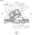
- Fig. 7 is a schematic diagram showing a state of second apparatus 2 tilted in first direction 101.
- second apparatus 2 When a user pulls cord 7 in first direction 101, second apparatus 2 is tilted toward first direction 101 with respect to first apparatus 1.
- projection 49 of second apparatus 2 When projection 49 of second apparatus 2 is tilted in first direction 101, projection 49 comes in contact with first wall surface 31.
- An angle of tilting at the time when projection 49 comes in contact with first wall surface 31 on the side of first direction 101 is defined as a first angle ⁇ 1.
- First angle ⁇ 1 is an angle formed between first wall surface 31 and second outer circumferential surface 42 at the time when projection 49 comes in contact with first wall surface 31 on the side of first direction 101.
- projection 49 When projection 49 comes in contact with first wall surface 31, projection 49 may be distant from first contact portion 10. When the user further pulls cord 7 on the side of first direction 101 after projection 49 comes in contact with first wall surface 31, projection 49 pivots on the side of first direction 101 with a point of contact between first wall surface 31 and projection 49 being defined as a fulcrum. Second apparatus 2 is thus detached from first apparatus 1.
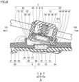
- Fig. 8 is a schematic diagram showing a state of second apparatus 2 tilted in second direction 102.
- second apparatus 2 When the user pulls cord 7 in second direction 102, second apparatus 2 is tilted on the side of second direction 102 with respect to first apparatus 1.
- projection 49 of second apparatus 2 is tilted in second direction 102, projection 49 comes in contact with first wall surface 31.
- An angle of tilting at the time when projection 49 comes in contact with first wall surface 31 on the side of second direction 102 is defined as a second angle ⁇ 2.
- Second angle ⁇ 2 is an angle formed between first wall surface 31 and second outer circumferential surface 42 at the time when projection 49 comes in contact with first wall surface 31 on the side of second direction 102.
- projection 49 when projection 49 comes in contact with first wall surface 31, projection 49 may come in contact with first contact portion 10. In other words, when projection 49 is tilted on the side of second direction 102, projection 49 may be in contact with both of first wall surface 31 and first contact portion 10.
- projection 49 pivots on the side of second direction 102 with a point of contact between first wall surface 31 and projection 49 being defined as a fulcrum. Second apparatus 2 is thus detached from first apparatus 1.
- the angle (first angle ⁇ 1) at the time when projection 49 is tilted in first direction 101 may be larger than the angle (second angle ⁇ 2) at the time when projection 49 is tilted in second direction 102.
- Fig. 9 is a schematic diagram showing a modification of the state of second apparatus 2 tilted in first direction 101.
- projection 49 when projection 49 comes in contact with first wall surface 31, projection 49 may come in contact with first contact portion 10.
- projection 49 when projection 49 is tilted on the side of first direction 101, projection 49 may come in contact with both of first wall surface 31 and first contact portion 10.
- Second outer circumferential surface 42 of projection 49 comes in contact with first wall surface 31.
- First inner circumferential surface portion 44 of projection 49 comes in contact with first outer circumferential surface 12 of first contact portion 10.
- the angle (first angle ⁇ 1) at the time when projection 49 is tilted in first direction 101 may be larger than the angle (second angle ⁇ 2) at the time when projection 49 is tilted in second direction 102.
- tilting may be stopped by contact of projection 49 with at least one of first contact portion 10 and first wall surface 31. From another point of view, tilting of projection 49 may be stopped by contact with first contact portion 10, by contact with first wall surface 31, or by contact with both of first contact portion 10 and first wall surface 31. Regarding an angle of tilting at the time when tilting of projection 49 is stopped, the angle (first angle ⁇ 1) at the time when projection 49 is tilted in first direction 101 may be larger than the angle (second angle ⁇ 2) at the time when projection 49 is tilted in second direction 102.
- first angle ⁇ 1 at the time when projection 49 is tilted in first direction 101
- second angle ⁇ 2 the angle at the time when projection 49 is tilted in second direction 102.
- connection structure 100 according to a second embodiment is different from connection structure 100 according to the first embodiment mainly in including a protrusion 70 in a C shape and otherwise similar to connection structure 100 according to the second embodiment.
- the construction different from connection structure 100 according to the first embodiment will mainly be described below.
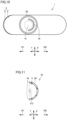
- Fig. 10 is a schematic top view showing a construction of first apparatus 1 of connection structure 100 according to the second embodiment.
- first apparatus 1 when viewed in magnetic force direction Z, first apparatus 1 includes a protrusion 70 substantially in a C shape. Protrusion 70 is curved as being convex toward second direction 102. Protrusion 70 opens on the side of first direction 101.
- Fig. 11 is a schematic cross-sectional view showing a construction of protrusion 70 according to the second embodiment. The cross-section shown in Fig. 11 is perpendicular to magnetic force direction Z.
- protrusion 70 includes a second arc-shaped portion 26, a third arc-shaped portion 17, and a pair of connection portions 18.
- One end of each of the pair of connection portions 18 is continuous to second arc-shaped portion 26 and the other end thereof is continuous to third arc-shaped portion 17.
- Second arc-shaped portion 26 is located on the side of second direction 102 relative to third arc-shaped portion 17.
- Third arc-shaped portion 17 is smaller in radius of curvature than second arc-shaped portion 26.
- a center of curvature of third arc-shaped portion 17 may coincide with a center of curvature of second arc-shaped portion 26.
- a central angle of each of second arc-shaped portion 26 and third arc-shaped portion 17 is set, for example, to 180°.
- the central angle of each of second arc-shaped portion 26 and third arc-shaped portion 17 may be, for example, not smaller than 150° and not larger than 210°.
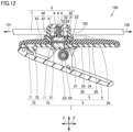
- Fig. 12 is a schematic cross-sectional view showing the construction of connection structure 100 according to the second embodiment.
- the cross-section shown in Fig. 12 is in parallel to each of magnetic force direction Z and lateral direction X.
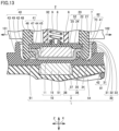
- Fig. 13 is an enlarged schematic diagram of a region XIII in Fig. 12 .
- first contact surface 11 may be located as high as first bottom surface 91.
- second contact surface 21 may be located under second lower surface 43 of hollow member 40.
- protrusion 70 is located on the side of second direction 102 relative to second outer surface 22 of second contact portion 20.
- protrusion 70 When second apparatus 2 is pulled in second direction 102, protrusion 70 may be in contact with second inner circumferential surface 41 of projection 49 on the side of second direction 102. From another point of view, when projection 49 is tilted toward second direction 102, pivot of projection 49 may be restricted by protrusion 70. In contrast, when projection 49 is tilted toward first direction 101, pivot of projection 49 does not have to be restricted by protrusion 70. When second apparatus 2 pivots as moving away from first apparatus 1, pivot of second apparatus 2 around the side of second direction 102 may be restricted more than pivot of second apparatus 2 around the side of first direction 101.
- FIG. 14 is a schematic cross-sectional view showing the construction of the attachment structure according to the third embodiment.
- An attachment structure 100 according to the third embodiment includes a bedclothes fitting instrument 1 and an instrument 2. Attachment structure 100 according to the third embodiment corresponds to connection structure 100 according to the first and second embodiments. Bedclothes fitting instrument 1 is fitted to bedclothes 61. Bedclothes fitting instrument 1 corresponds to first apparatus 1 of connection structure 100 according to the first and second embodiments. As shown in Fig. 14 , bedclothes fitting instrument 1 includes a bedclothes fixed portion 73, first contact portion 10, fastener 5, and annular wall portion 30. Bedclothes fixed portion 73 is fixed to bedclothes 61. For example, a pillow is provided as bedclothes 61, however, the bedclothes is not limited to the pillow. Bedclothes 61 may be, for example, a comforter (top cover), a mattress, a blanket, a bed, or a sheet.
- Bedclothes fixed portion 73 is composed of first pressing member 71 and second pressing member 72.
- a left end of first pinch member 3 serves as first pressing member 71.
- a left end of second pinch member 4 serves as second pressing member 72.
- shaft member 53 being defined as a fulcrum.
- An interval between first pressing member 71 and second pressing member 72 thus increases.
- Bedclothes 61 is arranged between first pressing member 71 and second pressing member 72. Bedclothes 61 is pinched by first pressing member 71 and second pressing member 72.
- Bedclothes fixed portion 73 is thus fixed to bedclothes 61.
- Bedclothes fixed portion 73 is located, for example, on the side of first direction 101 when viewed from first contact portion 10.
- Bedclothes fixed portion 73 is not located on an extension in magnetic force direction Z.
- Instrument 2 corresponds to second apparatus 2 of connection structure 100 according to the first and second embodiments.
- Instrument 2 is, for example, a strap.
- Instrument 2 may be a game console 62 including a strap.
- Instrument 2 mainly includes second contact portion 20, hollow member 40, cord holder 6, coil spring 8, reception plate 9, and cord 7.
- Bedclothes fitting instrument 1 and instrument 2 are brought in contact as being rotatable relatively to each other around magnetic force direction Z and being attachable to and detachable from each other as a result of contact between first contact portion 10 and second contact portion 20 with magnetic force of first magnetic element 51 and second magnetic element 52.
- bedclothes fitting instrument 1 and instrument 2 include a movement restriction portion 81.
- Movement restriction portion 81 restricts movement of first contact portion 10 and second contact portion 20 relative to each other in the direction perpendicular to magnetic force direction Z while first contact portion 10 and second contact portion 20 are brought in contact with each other.
- Movement restriction portion 81 is defined, for example, by first outer circumferential surface 12 and second inner circumferential surface 41 (see Fig. 3 ).
- First outer circumferential surface 12 is defined by first linear portion 13 and an arc of a length equal to or longer than a semicircular arc (first arc-shaped portion 27) (see Fig. 6 ).
- Movement restriction portion 81 may be defined by a combination of first wall surface 31 of annular wall portion 30 and second outer circumferential surface 42 of projection 49 in addition to or instead of the construction above.
- bedclothes fitting instrument 1 and instrument 2 include a pivot restriction portion 82.
- Pivot restriction portion 82 restricts pivot around the side opposite to the side of bedclothes fixed portion 73 with respect to first contact portion 10 more than pivot around the side of bedclothes fixed portion 73 when first contact portion 10 and second contact portion 20 pivot relative to each other as being moving away from each other in magnetic force direction Z from the state that first contact portion 10 and second contact portion 20 are brought in contact with each other.
- pivot restriction portion 82 may be defined by first outer circumferential surface 12 of first contact portion 10 and second inner circumferential surface 41 of projection 49.
- Pivot restriction portion 82 does not have to restrict pivot around the side of bedclothes fixed portion 73 but may restrict pivot around the side opposite to the side of bedclothes fixed portion 73 with respect to first contact portion 10 when first contact portion 10 and second contact portion 20 pivot relative to each other as being moving away from each other in magnetic force direction Z from the state that first contact portion 10 and second contact portion 20 are brought in contact with each other. As shown in Figs.
- second inner circumferential surface 41 of projection 49 when second contact portion 20 pivots toward bedclothes fixed portion 73, second inner circumferential surface 41 of projection 49 does not come in contact with first outer circumferential surface 12 of first contact portion 10, and when second contact portion 20 pivots toward the side opposite to the side of bedclothes fixed portion 73, second inner circumferential surface 41 of projection 49 may come in contact with first outer circumferential surface 12 of first contact portion 10.
- pivot restriction portion 82 may be defined by protrusion 70 and second inner circumferential surface 41 of projection 49.
- second inner circumferential surface 41 of projection 49 on the side of bedclothes fixed portion 73 does not come in contact with protrusion 70, and when second contact portion 20 pivots toward the side opposite to the side of bedclothes fixed portion 73, second inner circumferential surface 41 of projection 49 on the side opposite to the side of bedclothes fixed portion 73 may come in contact with protrusion 70 (see Fig. 13 ).
- An angle of restriction of pivot of instrument 2 at the time of pivot of instrument 2 around the side of bedclothes fixed portion 73 when first contact portion 10 and second contact portion 20 pivot relative to each other as being moving away from each other in magnetic force direction Z from the state that first contact portion 10 and second contact portion 20 are brought in contact with each other may be larger than an angle of restriction of pivot of instrument 2 at the time of pivot of instrument 2 around the side opposite to the side of bedclothes fixed portion 73 with respect to first contact portion 10.
- an angle (first angle ⁇ 1) of restriction of pivot of instrument 2 at the time of pivot of instrument 2 around the side of bedclothes fixed portion 73 may be larger than an angle (second angle ⁇ 2) of restriction of pivot of instrument 2 at the time of pivot of instrument 2 around the side opposite to the side of bedclothes fixed portion 73 (see Figs. 8 and 9 ).
- first apparatus 1 is not limited to bedclothes fitting instrument 1.
- First apparatus 1 may be an electronic device, a peripheral device of an electronic device, furniture, apparel, accessories, toys, or the like.
- Fixed portion 73 of first apparatus 1 is, for example, a clip, however, it is not limited to the clip.
- Fixed portion 73 of first apparatus 1 may be, for example, a suction cup, a hook, or the like.
- First apparatus 1 may be attached to an object other than bedclothes 61.
- First apparatus 1 may be attached, for example, to clothing such as a shirt or furniture such as a desk.
- Second apparatus 2 is, for example, a strap, however, it is not limited to the strap.
- Second apparatus 2 may be an electronic device, a peripheral device of an electronic device, furniture, apparel, accessories, toys, or the like.
- Second apparatus 2 may be an attachment tool such as a clip.
- Pivot restriction portion 82 is not limited to such a construction as above that the wall surface abuts earlier in pivot toward one side than in pivot toward the other side.
- Pivot restriction portion 82 may be constructed, for example, such that greater force is required in pivot toward one side than in pivot toward the other side.
- a buffer material may be used.
- another magnet may further be provided such that stronger attraction force acts in pivot toward one side than in pivot toward the other side.
- Game console 62 includes, for example, a storage (not shown), a processor (not shown), and/or a display (not shown).
- the storage is implemented, for example, by a dynamic random access memory (DRAM).
- An application program such as a game may be stored in the storage.
- the processor may be able to perform information processing by reading an application program.
- An image generated as a result of information processing performed, for example, by the processor may be shown on the display.
Landscapes
- Engineering & Computer Science (AREA)
- General Engineering & Computer Science (AREA)
- Mechanical Engineering (AREA)
- Physics & Mathematics (AREA)
- Electromagnetism (AREA)
- Power Engineering (AREA)
- Signal Processing (AREA)
- Pivots And Pivotal Connections (AREA)
- Supports Or Holders For Household Use (AREA)
Abstract
Description
- The present disclosure relates to a connection structure and an attachment structure.
-
Japanese Patent Laying-Open No. 2000-189227 - A connection structure according to the present disclosure includes a first apparatus and a second apparatus. The first apparatus includes a first bottom surface, a first contact portion, and a surrounding wall surface. The first contact portion protrudes from the first bottom surface, includes a first contact surface at a top portion, and includes a first magnetic element. The surrounding wall surface protrudes from the first bottom surface above the first contact surface to surround the top portion.
The second apparatus includes a second contact portion and a hollow projection. The second contact portion defines a second contact surface and includes a second magnetic element. The hollow projection surrounds the second contact portion. The first apparatus and the second apparatus are connected as being rotatable relatively to each other around a magnetic force direction and attachable to and detachable from each other as a result of contact between the first contact surface and the second contact surface by attraction of the first magnetic element and the second magnetic element to each other by magnetic force. The projection is located between the wall surface and the first contact portion with a clearance being interposed where the projection can be tilted in accordance with pulling including a direction component perpendicular to the magnetic force direction. In the first apparatus, a clearance between the top portion and the projection in a first direction of directions perpendicular to the magnetic force direction is larger than a clearance between the top portion and the projection in a second direction of the directions perpendicular to the magnetic force direction, the second direction being different from the first direction. - According to the connection structure according to the present disclosure, in the first apparatus, the clearance between the top portion and the projection in the first direction of the directions perpendicular to the magnetic force direction is larger than the clearance between the top portion and the projection in the second direction different from the first direction. Therefore, the projection is tilted to a larger extent on a side of the first direction than on the other side. Therefore, the second apparatus is more readily detached when it is pulled toward the first direction than toward the second direction. Thus, for example, when a user intentionally pulls the second apparatus in a certain direction, the second apparatus is readily detached, and in contrast, when the second apparatus is unintentionally pulled in another direction, easy detachment of the second apparatus can be suppressed.
- According to the connection structure, the wall surface may be in a circular surrounding shape. The projection may be annularly hollow. The first contact portion may be in such a shape that a part of an outer circumferential surface of a column is missing. Thus, regardless of a position of rotation of the second apparatus relative to the first apparatus, an angle of tilting at the time of tilting on the side of the second direction can be uniform.
- According to the connection structure, in a cross-section perpendicular to a magnetic force direction Z, the first contact portion may have an arc of a length equal to or longer than a semicircular arc. If the arc of the first contact portion in the cross-section is smaller than the semicircle while the first contact portion is accommodated in the inside of the annularly hollow projection, the first contact portion can move relatively in a lateral direction and wobbling occurs. If the first contact portion has an arc longer than the semicircle, on the other hand, the inner circumferential surface of the projection is caught by a portion of the arc longer than the semicircle. Therefore, wobbling in the lateral direction can be suppressed.
- According to the connection structure, in a cross-section perpendicular to the magnetic force direction, the first contact portion may include a linear portion and an arc-shaped portion continuous to opposing ends of the linear portion. A central angle of the arc-shaped portion may be larger than 180°. Wobbling in the lateral direction can thus further be suppressed.
- According to the connection structure, the second apparatus may include a second bottom surface. The second contact portion may protrude from the second bottom surface. If the second contact portion is located at a position deeper than the second bottom surface, in an attempt to bring the first contact portion and the second contact portion in contact with each other, the first contact portion may be caught by the second bottom surface and may not reach the second contact portion. When the second contact portion protrudes from the second bottom surface, the first contact surface and the second contact surface can more reliably be brought in contact with each other. Therefore, the first contact surface and the second contact surface being unintentionally distant from each other can be suppressed.
- According to the connection structure, the projection may protrude from the second bottom surface. The second contact portion may protrude such that the second contact surface is lower than the projection. Thus, influence by magnetism such as attraction and contact of an object close to the connection structure to the second contact surface can be suppressed.
- According to the connection structure, when the projection is tilted, tilting may be stopped by contact of the projection with at least one of the first contact portion and the wall surface. Regarding an angle of tilting at the time when tilting of the projection is stopped, the angle when the projection is tilted in the first direction may be larger than the angle when the projection is tilted in the second direction.
- Since tilting of the projection is stopped, the second apparatus is less likely to be detached from the first apparatus even when lateral force is further increased. Therefore, unintended removal of the second apparatus from the first apparatus can be suppressed. For removal of the second apparatus from a tilted state, force in the magnetic force direction is required. The second apparatus is more greatly tilted when it is tilted in the first direction than in the second direction. Since a distance between the first contact surface and the second contact surface is longer as the angle of tilting is larger, magnetic force is relatively weaker. Therefore, the second apparatus is more readily detached from the first apparatus when it is tilted in the first direction than in the second direction. In tilting the second apparatus in the second direction, magnetic force is relatively strong, however, magnetic force is weakened by tilting. Therefore, when force strong to some extent is applied, the second apparatus can be removed from the first apparatus.
- According to the connection structure, regarding an angle of tilting at the time when the projection is tilted and comes in contact with both of the first contact portion and the wall surface, the angle when the projection is tilted in the first direction may be larger than the angle when the projection is tilted in the second direction. Thus, the second apparatus can more readily be detached from the first apparatus when it is tilted in the first direction than in the second direction.
- According to the connection structure, regarding an angle of tilting at the time when the projection is tilted and comes in contact with the wall surface, the angle when the projection is tilted in the first direction may be larger than the angle when the projection is tilted in the second direction. Thus, the second apparatus can more readily be detached from the first apparatus when it is tilted in the first direction than in the second direction.
- According to the connection structure, the first magnetic element may include a first magnet. The second magnetic element may include a second magnet. A member that suppresses a magnetic flux density may be provided on the first contact surface or between the first contact surface and the first magnet or on the second contact surface or between the second contact surface and the second magnet.
- When only a magnet with strong magnetic force is employed, unintended attraction and contact may occur. When only a magnet with weak magnetic force is employed, on the other hand, the magnet is weak in attraction and contact force (difficulty in detachment) although it has attraction force (ease in attachment), and unintended removal may occur. If only a yolk member that suppresses a magnetic flux density is employed instead of a magnet, it has weak attraction force although it has attraction and contact force. Then, by employing a magnet with magnetic force strong to some extent and a yolk member, while the yolk member suppresses excessively large attraction and contact force of the magnet to suppress unintended removal, with attraction force of the magnet and the yolk member, the first apparatus and the second apparatus can swiftly be attracted and brought in contact with each other by being brought closer to each other to some extent.
- An attachment structure according to the present disclosure includes a bedclothes fitting instrument fitted to bedclothes and an instrument. The bedclothes fitting instrument includes a bedclothes fixed portion and a first contact portion. The bedclothes fixed portion is fixed to the bedclothes. The first contact portion includes a first magnetic element. The instrument includes a second contact portion. The second contact portion includes a second magnetic element. The bedclothes fitting instrument and the instrument are brought in contact as being rotatable relatively to each other around a magnetic force direction and attachable to and detachable from each other as a result of contact between the first contact portion and the second contact portion by magnetic force of the first magnetic element and the second magnetic element. The bedclothes fitting instrument and the instrument include a movement restriction portion. The movement restriction portion restricts movement of the first contact portion and the second contact portion relative to each other in a direction perpendicular the magnetic force direction while the first contact portion and the second contact portion are brought in contact with each other. The bedclothes fitting instrument and the instrument include a pivot restriction portion. The pivot restriction portion restricts pivot around a side opposite to a side of the bedclothes fixed portion with respect to the first contact portion, more than pivot around the side of the bedclothes fixed portion, when the first contact portion and the second contact portion pivot relatively to each other as moving away from each other in the magnetic force direction from a state that the first contact portion and the second contact portion are brought in contact with each other.
- According to the attachment structure according to the present disclosure, pivot around the side opposite to the side of the bedclothes fixed portion with respect to the first contact portion is restricted more than pivot around the side of the bedclothes fixed portion. Therefore, during sleep or the like, while removal of the second apparatus by unintended pulling in a direction away from the bedclothes is suppressed, the second apparatus can readily be detached when force to pull toward the bedclothes is intentionally applied thereto.
- According to the attachment structure, the instrument may include a projection that surrounds the second contact portion. The pivot restriction portion may be composed of a protrusion provided to surround a circumference of the first contact portion and an inner circumferential surface of the projection.
- According to the attachment structure, in a cross-section perpendicular to the magnetic force direction, the protrusion may be in a C shape.
- According to the attachment structure, the instrument may include a projection that surrounds the second contact portion. The pivot restriction portion may be composed of an outer circumferential surface of the first contact portion and an inner circumferential surface of the projection.
- According to the attachment structure, in a cross-section perpendicular to the magnetic force direction, the first contact portion may have an arc longer than a semicircle.
- According to the attachment structure, in a cross-section perpendicular to the magnetic force direction, the first contact portion may include a linear portion and an arc-shaped portion continuous to opposing ends of the linear portion. A central angle of the arc-shaped portion may be larger than 180°.
- According to the attachment structure, when the first contact portion and the second contact portion pivot relatively to each other as moving away from each other in the magnetic force direction from the state that the first contact portion and the second contact portion are brought in contact with each other, an angle at which pivot of the instrument is restricted when the instrument pivots around the side of the bedclothes fixed portion may be larger than an angle at which pivot of the instrument is restricted when the instrument pivots around the side opposite to the side of the bedclothes fixed portion with respect to the first contact portion. Thus, the second apparatus can more readily be detached from the first apparatus by tilting the second apparatus toward the bedclothes fixed portion than toward the side opposite to the side of the bedclothes fixed portion.
- According to the attachment structure, when the first contact portion and the second contact portion pivot relatively to each other as moving away from each other in the magnetic force direction from the state that the first contact portion and the second contact portion are brought in contact with each other, the pivot restriction portion does not restrict pivot around the side of the bedclothes fixed portion but may restrict pivot around the side opposite to the side of the bedclothes fixed portion with respect to the first contact portion. Thus, the second apparatus can more readily be detached from the first apparatus by tilting the second apparatus toward the bedclothes fixed portion than toward the side opposite to the side of the bedclothes fixed portion.
- The foregoing and other objects, features, aspects and advantages of the present invention will become more apparent from the following detailed description of the present invention when taken in conjunction with the accompanying drawings.
-
-
Fig. 1 shows an exemplary illustrative non-limiting drawing of an exploded schematic perspective view showing a construction of a connection structure according to a first embodiment. -
Fig. 2 shows an exemplary illustrative non-limiting drawing of a first schematic cross-sectional view showing the construction of the connection structure according to the first embodiment. -
Fig. 3 shows an exemplary illustrative non-limiting drawing of an enlarged schematic diagram of a region III inFig. 2 . -
Fig. 4 shows an exemplary illustrative non-limiting drawing of a second schematic cross-sectional view showing the construction of the connection structure according to the first embodiment. -
Fig. 5 shows an exemplary illustrative non-limiting drawing of a schematic top view showing a construction of a first apparatus of the connection structure according to the first embodiment. -
Fig. 6 shows an exemplary illustrative non-limiting drawing of a schematic cross-sectional view showing a construction of a first contact portion. -
Fig. 7 shows an exemplary illustrative non-limiting drawing of a schematic diagram showing a state of a second apparatus tilted in a first direction. -
Fig. 8 shows an exemplary illustrative non-limiting drawing of a schematic diagram showing a state of the second apparatus tilted in a second direction. -
Fig. 9 shows an exemplary illustrative non-limiting drawing of a schematic diagram showing a modification of the state of the second apparatus tilted in the first direction. -
Fig. 10 shows an exemplary illustrative non-limiting drawing of a schematic top view showing a construction of the first apparatus of the connection structure according to a second embodiment. -
Fig. 11 shows an exemplary illustrative non-limiting drawing of a schematic cross-sectional view showing a construction of a protrusion according to the second embodiment. -
Fig. 12 shows an exemplary illustrative non-limiting drawing of a schematic cross-sectional view showing a construction of the connection structure according to the second embodiment. -
Fig. 13 shows an exemplary illustrative non-limiting drawing of an enlarged schematic diagram of a region XIII inFig. 12 . -
Fig. 14 shows an exemplary illustrative non-limiting drawing of a schematic cross-sectional view showing a construction of an attachment structure according to a third embodiment. - An embodiment of the present disclosure will be described in detail with reference to the drawings. The same or corresponding elements in the drawings have the same reference characters allotted and description thereof will not be repeated.
- A construction of a
connection structure 100 according to a first embodiment will initially be described. -
Fig. 1 is an exploded schematic perspective view showing a construction ofconnection structure 100 according to the first embodiment. As shown inFig. 1 ,connection structure 100 according to the first embodiment mainly includes afirst apparatus 1 and asecond apparatus 2.First apparatus 1 mainly includes afirst contact portion 10, anannular wall portion 30, and afastener 5.First contact portion 10 is, for example, in such a shape that a part of an outer circumferential surface of a column is missing.Annular wall portion 30 is provided to surroundfirst contact portion 10.Fastener 5 includes afirst pinch member 3 and asecond pinch member 4.First contact portion 10 andannular wall portion 30 are provided infirst pinch member 3.Second apparatus 2 mainly includes ahollow member 40, acord 7, and acord holder 6.Cord 7 is attached to hollowmember 40. A part ofcord holder 6 is arranged in a region surrounded by an inner circumferential surface ofhollow member 40. -
Fig. 2 is a first schematic cross-sectional view showing the construction ofconnection structure 100 according to the first embodiment. As shown inFig. 2 ,fastener 5 further includes ashaft member 53 and aspring member 54.Spring member 54 is wound aroundshaft member 53.Spring member 54 has one end attached tofirst pinch member 3.Spring member 54 has the other end attached tosecond pinch member 4.Fastener 5 includes a fixingportion 73. Fixingportion 73 includes a first pressingmember 71 and a second pressingmember 72. While no external force is applied tofastener 5,fastener 5 is biased byspring member 54 such that first pressingmember 71 and second pressingmember 72 are brought closer to each other. - As shown in
Fig. 2 ,first apparatus 1 includes afirst contact portion 10.First contact portion 10 includes afirst contact surface 11 and a firstmagnetic element 51.Second apparatus 2 includes asecond contact portion 20.Second contact portion 20 includes asecond contact surface 21 and a secondmagnetic element 52. Infirst apparatus 1 andsecond apparatus 2, firstmagnetic element 51 and secondmagnetic element 52 are attracted to each other by magnetic force.First contact surface 11 andsecond contact surface 21 are thus brought in contact with each other. - A direction in parallel to a direction in which first
magnetic element 51 and secondmagnetic element 52 are attracted to each other by magnetic force is herein defined as a magnetic force direction Z. A direction fromfirst contact portion 10 towardsecond contact portion 20 is defined as an upper side. In contrast, a direction fromsecond contact portion 20 towardfirst contact portion 10 is defined as a lower side. A direction perpendicular to magnetic force direction Z is defined as an in-plane direction. A direction in parallel to a direction fromfirst contact portion 10 toward fixingportion 73 in the in-plane direction is defined as a lateral direction X. A direction perpendicular to each of magnetic force direction Z and lateral direction X is defined as a front-rear direction Y (seeFig. 4 ). - Each of a
first direction 101 and asecond direction 102 is a direction perpendicular to magnetic force direction Z. Each offirst direction 101 andsecond direction 102 is a direction withfirst contact portion 10 being defined as a reference. From another point of view, each offirst direction 101 andsecond direction 102 may be a direction radially extending fromfirst contact portion 10. Each offirst direction 101 andsecond direction 102 is, for example, in parallel to lateral direction X.
Second direction 102 is different fromfirst direction 101.Second direction 102 is, for example, a direction opposite tofirst direction 101.Second direction 102 should only be different fromfirst direction 101 and it is not limited to a direction opposite tofirst direction 101. -
First apparatus 1 andsecond apparatus 2 are connected to each other as being rotatable relatively to each other around magnetic force direction Z and attachable to and detachable from each other.Second contact surface 21 is slidable overfirst contact surface 11.Second apparatus 2 is rotatable with respect tofirst apparatus 1. A rotation axis ofsecond apparatus 2 is, for example, perpendicular tosecond contact surface 21.Second contact surface 21 may be circular. The rotation axis ofsecond apparatus 2 passes, for example, through a center ofsecond contact surface 21. -
Fig. 3 is an enlarged schematic diagram of a region III inFig. 2 . As shown inFig. 3 ,annular wall portion 30 includes afirst wall surface 31, asecond wall surface 32, and a firsttop surface 33.First wall surface 31 is in a surrounding shape.First wall surface 31 may be in a circular surrounding shape or a prismatic surrounding shape. Similarly,second wall surface 32 is in a surrounding shape.Second wall surface 32 may be in a circular surrounding shape or a prismatic surrounding shape.Second wall surface 32 is located on the outside offirst wall surface 31.Second wall surface 32 surroundsfirst wall surface 31. Firsttop surface 33 is continuous to each offirst wall surface 31 andsecond wall surface 32. -
First apparatus 1 includes afirst bottom surface 91 and a firstupper surface 34. Firstbottom surface 91 is continuous tofirst wall surface 31. Firstupper surface 34 is continuous tosecond wall surface 32. In magnetic force direction Z,first bottom surface 91 is located below firstupper surface 34. From another point of view, in magnetic force direction Z, firstupper surface 34 is located between firstbottom surface 91 and firsttop surface 33. In magnetic force direction Z,first bottom surface 91 may be located above firstupper surface 34. - As shown in
Fig. 3 ,first contact portion 10 protrudes from firstbottom surface 91.First contact portion 10 includes a first outercircumferential surface 12 and atop portion 14. First outercircumferential surface 12 is continuous to firstbottom surface 91. First outercircumferential surface 12 extends upward from firstbottom surface 91.Top portion 14 includesfirst contact surface 11 and a thirdupper surface 16. Thirdupper surface 16 is continuous tofirst contact surface 11.First contact surface 11 is in contact withsecond contact surface 21. Thirdupper surface 16 may be a portion not in contact withsecond contact surface 21.First wall surface 31 protrudes from firstbottom surface 91 abovefirst contact surface 11. In magnetic force direction Z, firsttop surface 33 is located abovefirst contact surface 11. In magnetic force direction Z,first contact surface 11 is located between firstbottom surface 91 and firsttop surface 33. - As shown in
Figs. 2 and3 ,first pinch member 3 includes a first plate-shapedmember 36 and a second plate-shapedmember 38. Each of first plate-shapedmember 36 and second plate-shapedmember 38 is made, for example, of a resin. First plate-shapedmember 36 includes a firstlower surface 35. Firstlower surface 35 is located opposite to each of firstbottom surface 91 and firstupper surface 34. Firstlower surface 35 is provided with afirst recess 37.First recess 37 is provided underfirst contact surface 11. - First
magnetic element 51 is composed, for example, of a magnet (a first magnet 15).First magnet 15 is arranged infirst recess 37. Second plate-shapedmember 38 is located under first plate-shapedmember 36.First magnet 15 lies between first plate-shapedmember 36 and second plate-shapedmember 38. A yolk member (not shown) that suppresses a magnetic flux density may be provided onfirst contact surface 11 or betweenfirst contact surface 11 andfirst magnet 15. The yolk member is made, for example, of iron.First contact surface 11 may be formed from the yolk member.First contact surface 11 may be composed, for example, of a resin orfirst magnet 15. - As shown in
Fig. 3 , secondmagnetic element 52 includes ayolk member 24 and asecond magnet 25.Yolk member 24 may be provided onsecond contact surface 21 or betweensecond contact surface 21 andsecond magnet 25. In magnetic force direction Z,second magnet 25 is located abovesecond contact surface 21. In magnetic force direction Z,second magnet 25 is provided betweenyolk member 24 and areception plate 9.Second contact surface 21 is formed, for example, fromyolk member 24.Second contact surface 21 may be composed, for example, of a resin or a magnet. -
Second apparatus 2 includes asecond bottom surface 92.Second bottom surface 92 is formed fromhollow member 40.Second bottom surface 92 may be opposed totop portion 14.Second bottom surface 92 may be opposed to firstbottom surface 91.Second contact portion 20 includes a secondouter surface 22. Secondouter surface 22 is continuous tosecond contact surface 21. Secondouter surface 22 is, for example, in a shape of a circular tube. In magnetic force direction Z,second bottom surface 92 is located abovesecond contact surface 21.Second contact portion 20 may protrude from secondbottom surface 92. In the in-plane direction,second bottom surface 92 is located on the outside ofsecond contact surface 21.Second contact portion 20 does not have to protrude from secondbottom surface 92. -
Hollow member 40 includes amain body portion 48 and aprojection 49.Projection 49 is continuous tomain body portion 48.Projection 49 is hollow.Projection 49 may be in a shape of an annular tube or a prismatic tube. Similarly,main body portion 48 is hollow.Main body portion 48 may be in a shape of an annular tube or a prismatic tube.Main body portion 48 andprojection 49 may integrally be formed.Projection 49 is provided undermain body portion 48.Projection 49 may protrude from secondbottom surface 92. -
Hollow member 40 includes a second innercircumferential surface 41, a second outercircumferential surface 42, and a secondlower surface 43. Second outercircumferential surface 42 is located on the outside of second innercircumferential surface 41. Each of second innercircumferential surface 41 and second outercircumferential surface 42 is continuous to secondlower surface 43. Second innercircumferential surface 41 is provided with asecond recess 46. A part ofyolk member 24 and a part ofcoil reception plate 9 may be inserted insecond recess 46. Each ofyolk member 24 andcoil reception plate 9 may be in contact withprojection 49. - Second inner
circumferential surface 41 includes a first innercircumferential surface portion 44, a second innercircumferential surface portion 45, and a third innercircumferential surface portion 47. First innercircumferential surface portion 44 is continuous to secondlower surface 43. First innercircumferential surface portion 44 is opposed to first outercircumferential surface 12. As shown inFig. 3 , first innercircumferential surface portion 44 may be inclined with respect to magnetic force direction Z such that an interval in lateral direction X is greater toward the lower side. In magnetic force direction Z, second innercircumferential surface portion 45 is located above first innercircumferential surface portion 44. Second innercircumferential surface portion 45 extends along magnetic force direction Z. Second innercircumferential surface portion 45 is in contact with secondouter surface 22 ofyolk member 24. - In magnetic force direction Z, third inner
circumferential surface portion 47 is located above second innercircumferential surface portion 45. In magnetic force direction Z,second recess 46 is located between second innercircumferential surface portion 45 and third innercircumferential surface portion 47. Secondlower surface 43, a part of second innercircumferential surface 41, and a part of second outercircumferential surface 42 are defined byprojection 49.Projection 49 surroundssecond contact portion 20.Second contact portion 20 protrudes such thatsecond contact surface 21 becomes lower thanprojection 49. In magnetic force direction Z,second contact surface 21 is located above secondlower surface 43 ofprojection 49. - As shown in
Fig. 3 ,projection 49 is located betweenfirst wall surface 31 andfirst contact portion 10 with a clearance where the projection can be tilted in accordance with pulling including a direction component perpendicular to magnetic force direction Z being interposed. In lateral direction X, a gap is provided betweenprojection 49 andfirst wall surface 31. In lateral direction X, a gap is provided betweenprojection 49 and first outercircumferential surface 12 offirst contact portion 10. - As shown in
Fig. 3 , a clearance (a first clearance C1) betweentop portion 14 offirst contact portion 10 andprojection 49 infirst direction 101 is larger than a clearance (a second clearance C2) betweentop portion 14 offirst contact portion 10 andprojection 49 insecond direction 102. First clearance C1 may be a distance between a boundary betweentop portion 14 and first outercircumferential surface 12 and a boundary between secondlower surface 43 and second innercircumferential surface 41 infirst direction 101. Second clearance C2 may be a distance between a boundary betweentop portion 14 and first outercircumferential surface 12 and a boundary between secondlower surface 43 and second innercircumferential surface 41 insecond direction 102. - Though an example in which the gap is provided between
projection 49 and first outercircumferential surface 12 offirst contact portion 10 is described above, the present disclosure is not limited to the construction above. In a connection structure according to a modification, no gap may be provided betweenprojection 49 and first outercircumferential surface 12 offirst contact portion 10. -
Fig. 4 is a second schematic cross-sectional view showing the construction ofconnection structure 100 according to the first embodiment. The cross-section shown inFig. 4 is in parallel to each of magnetic force direction Z and front-rear direction Y. The cross-section shown inFig. 4 is perpendicular to the cross-section shown inFig. 2 . - As shown in
Fig. 4 ,second apparatus 2 includes acoil spring 8 andreception plate 9.Coil spring 8 is provided onreception plate 9.Coil spring 8 is provided in a coilspring arrangement hole 6a provided incord holder 6.Cord holder 6 is biased upward bycoil spring 8.Reception plate 9 is arranged in a region surrounded by second innercircumferential surface 41 ofhollow member 40.Cord holder 6 is provided with a pair ofthird recesses 6b. The pair ofthird recesses 6b is provided on opposing sides of coilspring arrangement hole 6a.Cords 7 are arranged in the pair ofthird recesses 6b. Each of the pair ofthird recesses 6b is covered with second innercircumferential surface 41 ofhollow member 40. -
Fig. 5 is a schematic top view showing a construction offirst apparatus 1 ofconnection structure 100 according to the first embodiment. As shown inFig. 5 , when viewed in magnetic force direction Z,first wall surface 31 ofannular wall portion 30 surroundstop portion 14 offirst contact portion 10.First wall surface 31 is distant from first outercircumferential surface 12 offirst contact portion 10 around the entire circumference offirst wall surface 31. A clearance (a third clearance C3) betweenfirst wall surface 31 and first outercircumferential surface 12 infirst direction 101 is larger than a clearance (a fourth clearance C4) betweenfirst wall surface 31 and first outercircumferential surface 12 insecond direction 102. -
Fig. 6 is a schematic cross-sectional view showing a construction offirst contact portion 10. The cross-section shown inFig. 6 is perpendicular to magnetic force direction Z. As shown inFig. 6 , first outercircumferential surface 12 offirst contact portion 10 includes, for example, a first arc-shapedportion 27 and a firstlinear portion 13. First arc-shapedportion 27 is continuous to opposing ends of firstlinear portion 13. In the cross-section perpendicular to magnetic force direction Z, first outercircumferential surface 12 offirst contact portion 10 is substantially in a D shape. A direction in which firstlinear portion 13 extends may be perpendicular tofirst direction 101. From another point of view, firstlinear portion 13 may extend along front-rear direction Y. - As shown in
Fig. 6 , in the cross-section perpendicular to magnetic force direction Z,first contact portion 10 may have an arc longer than a semicircle. Specifically, arc-shapedportion 27 has an arc longer than a semicircle. From another point of view, a central angle θ3 of first arc-shapedportion 27 is larger than 180°. Though a lower limit of central angle θ3 of first arc-shapedportion 27 is not particularly limited, it may be, for example, not smaller than 200° or not smaller than 220°. Though an upper limit of central angle θ3 is not particularly limited, it may be, for example, not larger than 320° or not larger than 300°. -
Fig. 7 is a schematic diagram showing a state ofsecond apparatus 2 tilted infirst direction 101. When a user pullscord 7 infirst direction 101,second apparatus 2 is tilted towardfirst direction 101 with respect tofirst apparatus 1. As shown inFig. 7 , whenprojection 49 ofsecond apparatus 2 is tilted infirst direction 101,projection 49 comes in contact withfirst wall surface 31. An angle of tilting at the time whenprojection 49 comes in contact withfirst wall surface 31 on the side offirst direction 101 is defined as a first angle θ1. First angle θ1 is an angle formed betweenfirst wall surface 31 and second outercircumferential surface 42 at the time whenprojection 49 comes in contact withfirst wall surface 31 on the side offirst direction 101. - When
projection 49 comes in contact withfirst wall surface 31,projection 49 may be distant fromfirst contact portion 10. When the user further pullscord 7 on the side offirst direction 101 afterprojection 49 comes in contact withfirst wall surface 31,projection 49 pivots on the side offirst direction 101 with a point of contact betweenfirst wall surface 31 andprojection 49 being defined as a fulcrum.Second apparatus 2 is thus detached fromfirst apparatus 1. -
Fig. 8 is a schematic diagram showing a state ofsecond apparatus 2 tilted insecond direction 102. When the user pullscord 7 insecond direction 102,second apparatus 2 is tilted on the side ofsecond direction 102 with respect tofirst apparatus 1. As shown inFig. 8 , whenprojection 49 ofsecond apparatus 2 is tilted insecond direction 102,projection 49 comes in contact withfirst wall surface 31. An angle of tilting at the time whenprojection 49 comes in contact withfirst wall surface 31 on the side ofsecond direction 102 is defined as a second angle θ2. Second angle θ2 is an angle formed betweenfirst wall surface 31 and second outercircumferential surface 42 at the time whenprojection 49 comes in contact withfirst wall surface 31 on the side ofsecond direction 102. - As shown in
Fig. 8 , whenprojection 49 comes in contact withfirst wall surface 31,projection 49 may come in contact withfirst contact portion 10. In other words, whenprojection 49 is tilted on the side ofsecond direction 102,projection 49 may be in contact with both offirst wall surface 31 andfirst contact portion 10. When the user further pullscord 7 on the side ofsecond direction 102 afterprojection 49 comes in contact withfirst wall surface 31,projection 49 pivots on the side ofsecond direction 102 with a point of contact betweenfirst wall surface 31 andprojection 49 being defined as a fulcrum.Second apparatus 2 is thus detached fromfirst apparatus 1. - As shown in
Figs. 7 and8 , regarding an angle of tilting at the time whenprojection 49 is titled and comes in contact withfirst wall surface 31, the angle (first angle θ1) at the time whenprojection 49 is tilted infirst direction 101 may be larger than the angle (second angle θ2) at the time whenprojection 49 is tilted insecond direction 102. -
Fig. 9 is a schematic diagram showing a modification of the state ofsecond apparatus 2 tilted infirst direction 101. As shown inFig. 9 , whenprojection 49 comes in contact withfirst wall surface 31,projection 49 may come in contact withfirst contact portion 10. In other words, whenprojection 49 is tilted on the side offirst direction 101,projection 49 may come in contact with both offirst wall surface 31 andfirst contact portion 10. Second outercircumferential surface 42 ofprojection 49 comes in contact withfirst wall surface 31. First innercircumferential surface portion 44 ofprojection 49 comes in contact with first outercircumferential surface 12 offirst contact portion 10. - As shown in
Figs. 8 and9 , regarding an angle of tilting at the time whenprojection 49 is tilted and comes in contact with both offirst contact portion 10 andfirst wall surface 31, the angle (first angle θ1) at the time whenprojection 49 is tilted infirst direction 101 may be larger than the angle (second angle θ2) at the time whenprojection 49 is tilted insecond direction 102. - When
projection 49 is titled, tilting may be stopped by contact ofprojection 49 with at least one offirst contact portion 10 andfirst wall surface 31. From another point of view, tilting ofprojection 49 may be stopped by contact withfirst contact portion 10, by contact withfirst wall surface 31, or by contact with both offirst contact portion 10 andfirst wall surface 31. Regarding an angle of tilting at the time when tilting ofprojection 49 is stopped, the angle (first angle θ1) at the time whenprojection 49 is tilted infirst direction 101 may be larger than the angle (second angle θ2) at the time whenprojection 49 is tilted insecond direction 102. When tilting ofprojection 49 is stopped, a distance between firstmagnetic element 51 and secondmagnetic element 52 becomes longer. Therefore, in pullingsecond apparatus 2 upward for detachment, force necessary for detachment can be weaker. - A construction of
connection structure 100 according to a second embodiment will now be described.Connection structure 100 according to the second embodiment is different fromconnection structure 100 according to the first embodiment mainly in including aprotrusion 70 in a C shape and otherwise similar toconnection structure 100 according to the second embodiment. The construction different fromconnection structure 100 according to the first embodiment will mainly be described below. -
Fig. 10 is a schematic top view showing a construction offirst apparatus 1 ofconnection structure 100 according to the second embodiment. As shown inFig. 10 , when viewed in magnetic force direction Z,first apparatus 1 includes aprotrusion 70 substantially in a C shape.Protrusion 70 is curved as being convex towardsecond direction 102.Protrusion 70 opens on the side offirst direction 101.Fig. 11 is a schematic cross-sectional view showing a construction ofprotrusion 70 according to the second embodiment. The cross-section shown inFig. 11 is perpendicular to magnetic force direction Z. - As shown in
Fig. 11 ,protrusion 70 includes a second arc-shapedportion 26, a third arc-shapedportion 17, and a pair ofconnection portions 18. One end of each of the pair ofconnection portions 18 is continuous to second arc-shapedportion 26 and the other end thereof is continuous to third arc-shapedportion 17. Second arc-shapedportion 26 is located on the side ofsecond direction 102 relative to third arc-shapedportion 17. Third arc-shapedportion 17 is smaller in radius of curvature than second arc-shapedportion 26. A center of curvature of third arc-shapedportion 17 may coincide with a center of curvature of second arc-shapedportion 26. A central angle of each of second arc-shapedportion 26 and third arc-shapedportion 17 is set, for example, to 180°. The central angle of each of second arc-shapedportion 26 and third arc-shapedportion 17 may be, for example, not smaller than 150° and not larger than 210°. -
Fig. 12 is a schematic cross-sectional view showing the construction ofconnection structure 100 according to the second embodiment. The cross-section shown inFig. 12 is in parallel to each of magnetic force direction Z and lateral direction X.Fig. 13 is an enlarged schematic diagram of a region XIII inFig. 12 . - As shown in
Fig. 13 , in magnetic force direction Z,first contact surface 11 may be located as high as firstbottom surface 91. In magnetic force direction Z,second contact surface 21 may be located under secondlower surface 43 ofhollow member 40. In lateral direction X,protrusion 70 is located on the side ofsecond direction 102 relative to secondouter surface 22 ofsecond contact portion 20. - When
second apparatus 2 is pulled insecond direction 102,protrusion 70 may be in contact with second innercircumferential surface 41 ofprojection 49 on the side ofsecond direction 102. From another point of view, whenprojection 49 is tilted towardsecond direction 102, pivot ofprojection 49 may be restricted byprotrusion 70. In contrast, whenprojection 49 is tilted towardfirst direction 101, pivot ofprojection 49 does not have to be restricted byprotrusion 70. Whensecond apparatus 2 pivots as moving away fromfirst apparatus 1, pivot ofsecond apparatus 2 around the side ofsecond direction 102 may be restricted more than pivot ofsecond apparatus 2 around the side offirst direction 101. - A construction of an attachment structure according to a third embodiment will now be described.
Fig. 14 is a schematic cross-sectional view showing the construction of the attachment structure according to the third embodiment. - An
attachment structure 100 according to the third embodiment includes a bedclothesfitting instrument 1 and aninstrument 2.Attachment structure 100 according to the third embodiment corresponds toconnection structure 100 according to the first and second embodiments. Bedclothesfitting instrument 1 is fitted to bedclothes 61. Bedclothesfitting instrument 1 corresponds tofirst apparatus 1 ofconnection structure 100 according to the first and second embodiments. As shown inFig. 14 ,bedclothes fitting instrument 1 includes a bedclothes fixedportion 73,first contact portion 10,fastener 5, andannular wall portion 30. Bedclothes fixedportion 73 is fixed to bedclothes 61. For example, a pillow is provided asbedclothes 61, however, the bedclothes is not limited to the pillow.Bedclothes 61 may be, for example, a comforter (top cover), a mattress, a blanket, a bed, or a sheet. - Bedclothes fixed
portion 73 is composed of first pressingmember 71 and second pressingmember 72. A left end offirst pinch member 3 serves as first pressingmember 71. A left end ofsecond pinch member 4 serves as second pressingmember 72. When the user pinches a right end offirst pinch member 3 and a right end ofsecond pinch member 4, each offirst pinch member 3 andsecond pinch member 4 pivot withshaft member 53 being defined as a fulcrum. An interval between first pressingmember 71 and second pressingmember 72 thus increases.Bedclothes 61 is arranged between first pressingmember 71 and second pressingmember 72.Bedclothes 61 is pinched by first pressingmember 71 and second pressingmember 72. Bedclothes fixedportion 73 is thus fixed to bedclothes 61. Bedclothes fixedportion 73 is located, for example, on the side offirst direction 101 when viewed fromfirst contact portion 10. Bedclothes fixedportion 73 is not located on an extension in magnetic force direction Z. -
Instrument 2 corresponds tosecond apparatus 2 ofconnection structure 100 according to the first and second embodiments.Instrument 2 is, for example, a strap.Instrument 2 may be agame console 62 including a strap.Instrument 2 mainly includessecond contact portion 20,hollow member 40,cord holder 6,coil spring 8,reception plate 9, andcord 7. Bedclothesfitting instrument 1 andinstrument 2 are brought in contact as being rotatable relatively to each other around magnetic force direction Z and being attachable to and detachable from each other as a result of contact betweenfirst contact portion 10 andsecond contact portion 20 with magnetic force of firstmagnetic element 51 and secondmagnetic element 52. - As shown in
Figs. 3 and13 ,bedclothes fitting instrument 1 andinstrument 2 include amovement restriction portion 81.Movement restriction portion 81 restricts movement offirst contact portion 10 andsecond contact portion 20 relative to each other in the direction perpendicular to magnetic force direction Z whilefirst contact portion 10 andsecond contact portion 20 are brought in contact with each other.Movement restriction portion 81 is defined, for example, by first outercircumferential surface 12 and second inner circumferential surface 41 (seeFig. 3 ). First outercircumferential surface 12 is defined by firstlinear portion 13 and an arc of a length equal to or longer than a semicircular arc (first arc-shaped portion 27) (seeFig. 6 ). Wobbling in lateral direction X ofinstrument 2 is suppressed by first outercircumferential surface 12.Movement restriction portion 81 may be defined by a combination offirst wall surface 31 ofannular wall portion 30 and second outercircumferential surface 42 ofprojection 49 in addition to or instead of the construction above. - As shown in
Fig. 3 ,bedclothes fitting instrument 1 andinstrument 2 include apivot restriction portion 82.Pivot restriction portion 82 restricts pivot around the side opposite to the side of bedclothes fixedportion 73 with respect tofirst contact portion 10 more than pivot around the side of bedclothes fixedportion 73 whenfirst contact portion 10 andsecond contact portion 20 pivot relative to each other as being moving away from each other in magnetic force direction Z from the state thatfirst contact portion 10 andsecond contact portion 20 are brought in contact with each other. As shown inFig. 3 ,pivot restriction portion 82 may be defined by first outercircumferential surface 12 offirst contact portion 10 and second innercircumferential surface 41 ofprojection 49. -
Pivot restriction portion 82 does not have to restrict pivot around the side of bedclothes fixedportion 73 but may restrict pivot around the side opposite to the side of bedclothes fixedportion 73 with respect tofirst contact portion 10 whenfirst contact portion 10 andsecond contact portion 20 pivot relative to each other as being moving away from each other in magnetic force direction Z from the state thatfirst contact portion 10 andsecond contact portion 20 are brought in contact with each other. As shown inFigs. 7 and8 , whensecond contact portion 20 pivots toward bedclothes fixedportion 73, second innercircumferential surface 41 ofprojection 49 does not come in contact with first outercircumferential surface 12 offirst contact portion 10, and whensecond contact portion 20 pivots toward the side opposite to the side of bedclothes fixedportion 73, second innercircumferential surface 41 ofprojection 49 may come in contact with first outercircumferential surface 12 offirst contact portion 10. - As shown in
Fig. 13 ,pivot restriction portion 82 may be defined byprotrusion 70 and second innercircumferential surface 41 ofprojection 49. Whensecond contact portion 20 pivots toward bedclothes fixedportion 73, second innercircumferential surface 41 ofprojection 49 on the side of bedclothes fixedportion 73 does not come in contact withprotrusion 70, and whensecond contact portion 20 pivots toward the side opposite to the side of bedclothes fixedportion 73, second innercircumferential surface 41 ofprojection 49 on the side opposite to the side of bedclothes fixedportion 73 may come in contact with protrusion 70 (seeFig. 13 ). - An angle of restriction of pivot of
instrument 2 at the time of pivot ofinstrument 2 around the side of bedclothes fixedportion 73 whenfirst contact portion 10 andsecond contact portion 20 pivot relative to each other as being moving away from each other in magnetic force direction Z from the state thatfirst contact portion 10 andsecond contact portion 20 are brought in contact with each other may be larger than an angle of restriction of pivot ofinstrument 2 at the time of pivot ofinstrument 2 around the side opposite to the side of bedclothes fixedportion 73 with respect tofirst contact portion 10. From another point of view, an angle (first angle θ1) of restriction of pivot ofinstrument 2 at the time of pivot ofinstrument 2 around the side of bedclothes fixedportion 73 may be larger than an angle (second angle θ2) of restriction of pivot ofinstrument 2 at the time of pivot ofinstrument 2 around the side opposite to the side of bedclothes fixed portion 73 (seeFigs. 8 and9 ). - Though bedclothes
fitting instrument 1 is described above by way of example offirst apparatus 1,first apparatus 1 is not limited to bedclothesfitting instrument 1.First apparatus 1 may be an electronic device, a peripheral device of an electronic device, furniture, apparel, accessories, toys, or the like. Fixedportion 73 offirst apparatus 1 is, for example, a clip, however, it is not limited to the clip. Fixedportion 73 offirst apparatus 1 may be, for example, a suction cup, a hook, or the like.First apparatus 1 may be attached to an object other thanbedclothes 61.First apparatus 1 may be attached, for example, to clothing such as a shirt or furniture such as a desk. -
Second apparatus 2 is, for example, a strap, however, it is not limited to the strap.Second apparatus 2 may be an electronic device, a peripheral device of an electronic device, furniture, apparel, accessories, toys, or the like.Second apparatus 2 may be an attachment tool such as a clip. -
Pivot restriction portion 82 is not limited to such a construction as above that the wall surface abuts earlier in pivot toward one side than in pivot toward the other side.Pivot restriction portion 82 may be constructed, for example, such that greater force is required in pivot toward one side than in pivot toward the other side. In order to adjust force to restrict pivot, for example, a buffer material may be used. Alternatively, another magnet may further be provided such that stronger attraction force acts in pivot toward one side than in pivot toward the other side. -
Game console 62 includes, for example, a storage (not shown), a processor (not shown), and/or a display (not shown). The storage is implemented, for example, by a dynamic random access memory (DRAM). An application program such as a game may be stored in the storage. The processor may be able to perform information processing by reading an application program. An image generated as a result of information processing performed, for example, by the processor may be shown on the display. - Although the present invention has been described and illustrated in detail, it is clearly understood that the same is by way of illustration and example only and is not to be taken by way of limitation, the scope of the present invention being interpreted by the terms of the appended claims.
Claims (15)
- A connection structure (100) comprising:a first apparatus (1); anda second apparatus (2), whereinthe first apparatus includesa first bottom surface (91),a first contact portion (10) that protrudes from the first bottom surface, includes a first contact surface (11) at a top portion (14), and includes a first magnetic element (51), anda surrounding wall surface (31) that protrudes from the first bottom surface above the first contact surface to surround the top portion,the second apparatus includesa second contact portion (20) that defines a second contact surface (21) and includes a second magnetic element (52), anda hollow projection (49) that surrounds the second contact portion,the first apparatus and the second apparatus are connected as being rotatable relatively to each other around a magnetic force direction and attachable to and detachable from each other as a result of contact between the first contact surface and the second contact surface by attraction of the first magnetic element and the second magnetic element to each other by magnetic force,the projection is located between the wall surface and the first contact portion with a clearance being interposed where the projection can be tilted in accordance with pulling including a direction component perpendicular to the magnetic force direction, andin the first apparatus, a clearance between the top portion and the projection in a first direction of directions perpendicular to the magnetic force direction is larger than a clearance between the top portion and the projection in a second direction of the directions perpendicular to the magnetic force direction, the second direction being different from the first direction.
- The connection structure according to claim 1, whereinthe wall surface is in a circular surrounding shape,the projection is annularly hollow, andthe first contact portion is in such a shape that a part of an outer circumferential surface of a column is missing.
- The connection structure according to claim 2, wherein
in a cross-section perpendicular to the magnetic force direction, the first contact portion has an arc of a length equal to or longer than a semicircular arc. - The connection structure according to any one of claims 1 to 3, whereinthe second apparatus includes a second bottom surface (92), andthe second contact portion protrudes from the second bottom surface.
- The connection structure according to claim 4, whereinthe projection protrudes from the second bottom surface, andthe second contact portion protrudes such that the second contact surface is lower than the projection.
- The connection structure according to any one of claims 1 to 5, whereinwhen the projection is tilted, tilting is stopped by contact of the projection with at least one of the first contact portion and the wall surface, andregarding an angle of tilting when tilting of the projection is stopped, the angle when the projection is tilted in the first direction is larger than the angle when the projection is tilted in the second direction.
- The connection structure according to any one of claims 1 to 5, wherein
regarding an angle of tilting when the projection is tilted and comes in contact with both of the first contact portion and the wall surface, the angle when the projection is tilted in the first direction is larger than the angle when the projection is tilted in the second direction. - The connection structure according to any one of claims 1 to 5, wherein
regarding an angle of tilting when the projection is tilted and comes in contact with the wall surface, the angle when the projection is tilted in the first direction is larger than the angle when the projection is tilted in the second direction. - The connection structure according to any one of claims 1 to 8, whereinthe first magnetic element includes a first magnet (15),the second magnetic element includes a second magnet (25), anda member (24) that suppresses a magnetic flux density is provided on the first contact surface or between the first contact surface and the first magnet or on the second contact surface or between the second contact surface and the second magnet.
- An attachment structure (100) comprising:a bedclothes fitting instrument (1) fitted to bedclothes; andan instrument (2), whereinthe bedclothes fitting instrument includesa bedclothes fixed portion (73) fixed to the bedclothes, anda first contact portion (10) including a first magnetic element (51),the instrument includes a second contact portion (20) including a second magnetic element (52),the bedclothes fitting instrument and the instrument are brought in contact as being rotatable relatively to each other around a magnetic force direction and attachable to and detachable from each other as a result of contact between the first contact portion and the second contact portion by magnetic force of the first magnetic element and the second magnetic element,the bedclothes fitting instrument and the instrument include a movement restriction portion that restricts movement of the first contact portion and the second contact portion relative to each other in a direction perpendicular the magnetic force direction while the first contact portion and the second contact portion are brought in contact with each other, andthe bedclothes fitting instrument and the instrument include a pivot restriction portion that restricts pivot around a side opposite to a side of the bedclothes fixed portion with respect to the first contact portion, more than pivot around the side of the bedclothes fixed portion, when the first contact portion and the second contact portion pivot relatively to each other as moving away from each other in the magnetic force direction from a state that the first contact portion and the second contact portion are brought in contact with each other.
- The attachment structure according to claim 10, whereinthe instrument includes a projection that surrounds the second contact portion, andthe pivot restriction portion is composed of a protrusion provided to surround a part of a circumference of the first contact portion and an inner circumferential surface of the projection.
- The attachment structure according to claim 10, whereinthe instrument includes a projection (49) that surrounds the second contact portion, andthe pivot restriction portion is composed of an outer circumferential surface of the first contact portion and an inner circumferential surface of the projection.
- The attachment structure according to claim 12, wherein
in a cross-section perpendicular to the magnetic force direction, the first contact portion has an arc longer than a semicircle. - The attachment structure according to claim 12 or 13, wherein
when the first contact portion and the second contact portion pivot relatively to each other as moving away from each other in the magnetic force direction from the state that the first contact portion and the second contact portion are brought in contact with each other, an angle at which pivot of the instrument is restricted when the instrument pivots around the side of the bedclothes fixed portion is larger than an angle at which pivot of the instrument is restricted when the instrument pivots around the side opposite to the side of the bedclothes fixed portion with respect to the first contact portion. - The attachment structure according to any one of claims 10 to 13, wherein
when the first contact portion and the second contact portion pivot relatively to each other as moving away from each other in the magnetic force direction from the state that the first contact portion and the second contact portion are brought in contact with each other, the pivot restriction portion does not restrict pivot around the side of the bedclothes fixed portion but restricts pivot around the side opposite to the side of the bedclothes fixed portion with respect to the first contact portion.
Applications Claiming Priority (1)
| Application Number | Priority Date | Filing Date | Title |
|---|---|---|---|
| JP2021212359A JP7720777B2 (en) | 2021-12-27 | 2021-12-27 | Connection and mounting structures |
Publications (2)
| Publication Number | Publication Date |
|---|---|
| EP4230087A1 true EP4230087A1 (en) | 2023-08-23 |
| EP4230087B1 EP4230087B1 (en) | 2024-11-27 |
Family
ID=84537998
Family Applications (1)
| Application Number | Title | Priority Date | Filing Date |
|---|---|---|---|
| EP22214560.9A Active EP4230087B1 (en) | 2021-12-27 | 2022-12-19 | Releasable magnetic structure for attaching devices |
Country Status (3)
| Country | Link |
|---|---|
| US (2) | US12171340B2 (en) |
| EP (1) | EP4230087B1 (en) |
| JP (2) | JP7720777B2 (en) |
Families Citing this family (4)
| Publication number | Priority date | Publication date | Assignee | Title |
|---|---|---|---|---|
| CA3102954A1 (en) * | 2018-06-06 | 2019-12-12 | Patrick NEY | Static structure having a plurality of detachable mobile components |
| US20230066732A1 (en) * | 2021-07-13 | 2023-03-02 | Gray Matters, Inc. | Bed covering retention assembly |
| JP1753967S (en) * | 2023-02-09 | 2023-09-27 | strap with clip | |
| JP2026506985A (en) * | 2023-02-28 | 2026-02-27 | ボストン サイエンティフィック サイムド,インコーポレイテッド | Medical systems, devices, and related methods for rotatably or pivotally coupling medical devices |
Citations (6)
| Publication number | Priority date | Publication date | Assignee | Title |
|---|---|---|---|---|
| US5404602A (en) * | 1994-01-24 | 1995-04-11 | Kondo; Victor F. | Bedclothes anchoring apparatus |
| JP2000189227A (en) | 1998-12-28 | 2000-07-11 | Kyoei Sangyo Kk | Mobile phone holder |
| US6888940B1 (en) * | 2000-04-12 | 2005-05-03 | Daniel Deppen | Magnetic holder for cell phones and the like |
| WO2019183227A1 (en) * | 2018-03-20 | 2019-09-26 | Mobile Tech, Inc. | Docking system for portable computing device |
| US20200237083A1 (en) * | 2019-01-25 | 2020-07-30 | Huang Jin | Phone clip holder |
| US20210046885A1 (en) * | 2019-07-31 | 2021-02-18 | Peak Design | Mobile device mounting system |
Family Cites Families (10)
| Publication number | Priority date | Publication date | Assignee | Title |
|---|---|---|---|---|
| JPS55125188U (en) * | 1979-02-28 | 1980-09-04 | ||
| US4479596A (en) * | 1983-06-20 | 1984-10-30 | Swanson Albert W | Carrying case for portable electronic paging devices |
| JPS61258406A (en) * | 1985-05-13 | 1986-11-15 | Taamo:Kk | Engaging means |
| US20030000976A1 (en) * | 2000-09-13 | 2003-01-02 | Ron Malhotra | Holder for a cellular telephone in combination with a clip adapted to be secured to clothing articles and clothing accessories |
| JP4871968B2 (en) * | 2009-02-17 | 2012-02-08 | 日立Geニュークリア・エナジー株式会社 | Heavy structure installation method |
| US9629447B1 (en) * | 2015-10-01 | 2017-04-25 | Cheryl A. Martel | Cellular phone tethering system |
| US10026535B2 (en) | 2015-12-31 | 2018-07-17 | Catch Latch, Llc | Mechanical magnetic connector structure |
| JP6152463B1 (en) * | 2016-07-29 | 2017-06-21 | 株式会社フルヤ金属 | thermocouple |
| JP6684232B2 (en) * | 2017-01-06 | 2020-04-22 | 任天堂株式会社 | Device holding structure |
| JP7308699B2 (en) * | 2019-09-03 | 2023-07-14 | 東京エレクトロン株式会社 | Thermocouple structure, heat treatment apparatus, and method for manufacturing thermocouple structure |
-
2021
- 2021-12-27 JP JP2021212359A patent/JP7720777B2/en active Active
-
2022
- 2022-12-14 US US18/081,314 patent/US12171340B2/en active Active
- 2022-12-19 EP EP22214560.9A patent/EP4230087B1/en active Active
-
2024
- 2024-11-15 US US18/948,630 patent/US20250064220A1/en active Pending
-
2025
- 2025-07-28 JP JP2025125447A patent/JP7836454B2/en active Active
Patent Citations (6)
| Publication number | Priority date | Publication date | Assignee | Title |
|---|---|---|---|---|
| US5404602A (en) * | 1994-01-24 | 1995-04-11 | Kondo; Victor F. | Bedclothes anchoring apparatus |
| JP2000189227A (en) | 1998-12-28 | 2000-07-11 | Kyoei Sangyo Kk | Mobile phone holder |
| US6888940B1 (en) * | 2000-04-12 | 2005-05-03 | Daniel Deppen | Magnetic holder for cell phones and the like |
| WO2019183227A1 (en) * | 2018-03-20 | 2019-09-26 | Mobile Tech, Inc. | Docking system for portable computing device |
| US20200237083A1 (en) * | 2019-01-25 | 2020-07-30 | Huang Jin | Phone clip holder |
| US20210046885A1 (en) * | 2019-07-31 | 2021-02-18 | Peak Design | Mobile device mounting system |
Also Published As
| Publication number | Publication date |
|---|---|
| JP7836454B2 (en) | 2026-03-26 |
| US20230200551A1 (en) | 2023-06-29 |
| US12171340B2 (en) | 2024-12-24 |
| US20250064220A1 (en) | 2025-02-27 |
| EP4230087B1 (en) | 2024-11-27 |
| JP2023096532A (en) | 2023-07-07 |
| JP7720777B2 (en) | 2025-08-08 |
| JP2025142270A (en) | 2025-09-30 |
Similar Documents
| Publication | Publication Date | Title |
|---|---|---|
| US12171340B2 (en) | Connection structure and attachment structure | |
| US10976781B2 (en) | Apparatus holding structure | |
| JP2521801Y2 (en) | Noise absorber | |
| US9743745B2 (en) | Optimized cord clip | |
| US20100308089A1 (en) | Camera device | |
| KR200496958Y1 (en) | Smartphone detachable auxiliary battery device with holder device | |
| US20200367632A1 (en) | Clipping Device with Integrated Finger Trap | |
| US12424793B2 (en) | Plug lock mechanism | |
| JP7082685B2 (en) | Snap button and female snap button | |
| JPH0960390A (en) | magnet catch | |
| JP2019061687A (en) | Holding structure of apparatus | |
| JP3255107U (en) | Fan stand | |
| JP3255340U (en) | Hanging storage case | |
| JP5752023B2 (en) | Cord clip | |
| JP2824245B2 (en) | Engagement structure between inner bite and bobbin case | |
| CN210960574U (en) | Reinforced I-shaped buckle | |
| JP2024007237A (en) | sewing machine | |
| JP3076421U (en) | Cord holder | |
| JP4744361B2 (en) | Earphone cord holder | |
| JP3001004U (en) | Soft sword | |
| JP2933598B1 (en) | Antenna device for portable radio equipment | |
| JP2026056376A (en) | A clothespin and a hanger equipped with such clothespin | |
| JP2004232770A (en) | Damper and box body opening-closing device | |
| JP2605437Y2 (en) | Microphone holder | |
| JPH0988931A (en) | Hanging equipment locking structure for small equipment |
Legal Events
| Date | Code | Title | Description |
|---|---|---|---|
| PUAI | Public reference made under article 153(3) epc to a published international application that has entered the european phase |
Free format text: ORIGINAL CODE: 0009012 |
|
| STAA | Information on the status of an ep patent application or granted ep patent |
Free format text: STATUS: THE APPLICATION HAS BEEN PUBLISHED |
|
| AK | Designated contracting states |
Kind code of ref document: A1 Designated state(s): AL AT BE BG CH CY CZ DE DK EE ES FI FR GB GR HR HU IE IS IT LI LT LU LV MC ME MK MT NL NO PL PT RO RS SE SI SK SM TR |
|
| STAA | Information on the status of an ep patent application or granted ep patent |
Free format text: STATUS: REQUEST FOR EXAMINATION WAS MADE |
|
| 17P | Request for examination filed |
Effective date: 20240131 |
|
| RBV | Designated contracting states (corrected) |
Designated state(s): AL AT BE BG CH CY CZ DE DK EE ES FI FR GB GR HR HU IE IS IT LI LT LU LV MC ME MK MT NL NO PL PT RO RS SE SI SK SM TR |
|
| GRAP | Despatch of communication of intention to grant a patent |
Free format text: ORIGINAL CODE: EPIDOSNIGR1 |
|
| STAA | Information on the status of an ep patent application or granted ep patent |
Free format text: STATUS: GRANT OF PATENT IS INTENDED |
|
| RIC1 | Information provided on ipc code assigned before grant |
Ipc: F16M 13/02 20060101ALI20240531BHEP Ipc: F16G 11/10 20060101ALI20240531BHEP Ipc: G06F 1/16 20060101ALI20240531BHEP Ipc: H04M 1/04 20060101ALI20240531BHEP Ipc: F16M 11/04 20060101ALI20240531BHEP Ipc: A47C 21/02 20060101AFI20240531BHEP |
|
| INTG | Intention to grant announced |
Effective date: 20240621 |
|
| GRAS | Grant fee paid |
Free format text: ORIGINAL CODE: EPIDOSNIGR3 |
|
| GRAA | (expected) grant |
Free format text: ORIGINAL CODE: 0009210 |
|
| STAA | Information on the status of an ep patent application or granted ep patent |
Free format text: STATUS: THE PATENT HAS BEEN GRANTED |
|
| AK | Designated contracting states |
Kind code of ref document: B1 Designated state(s): AL AT BE BG CH CY CZ DE DK EE ES FI FR GB GR HR HU IE IS IT LI LT LU LV MC ME MK MT NL NO PL PT RO RS SE SI SK SM TR |
|
| REG | Reference to a national code |
Ref country code: GB Ref legal event code: FG4D |
|
| REG | Reference to a national code |
Ref country code: CH Ref legal event code: EP |
|
| P01 | Opt-out of the competence of the unified patent court (upc) registered |
Free format text: CASE NUMBER: APP_58406/2024 Effective date: 20241025 |
|
| REG | Reference to a national code |
Ref country code: IE Ref legal event code: FG4D |
|
| REG | Reference to a national code |
Ref country code: DE Ref legal event code: R096 Ref document number: 602022008168 Country of ref document: DE |
|
| REG | Reference to a national code |
Ref country code: LT Ref legal event code: MG9D |
|
| REG | Reference to a national code |
Ref country code: NL Ref legal event code: MP Effective date: 20241127 |
|
| PG25 | Lapsed in a contracting state [announced via postgrant information from national office to epo] |
Ref country code: PT Free format text: LAPSE BECAUSE OF FAILURE TO SUBMIT A TRANSLATION OF THE DESCRIPTION OR TO PAY THE FEE WITHIN THE PRESCRIBED TIME-LIMIT Effective date: 20250327 Ref country code: IS Free format text: LAPSE BECAUSE OF FAILURE TO SUBMIT A TRANSLATION OF THE DESCRIPTION OR TO PAY THE FEE WITHIN THE PRESCRIBED TIME-LIMIT Effective date: 20250327 Ref country code: HR Free format text: LAPSE BECAUSE OF FAILURE TO SUBMIT A TRANSLATION OF THE DESCRIPTION OR TO PAY THE FEE WITHIN THE PRESCRIBED TIME-LIMIT Effective date: 20241127 |
|
| PG25 | Lapsed in a contracting state [announced via postgrant information from national office to epo] |
Ref country code: FI Free format text: LAPSE BECAUSE OF FAILURE TO SUBMIT A TRANSLATION OF THE DESCRIPTION OR TO PAY THE FEE WITHIN THE PRESCRIBED TIME-LIMIT Effective date: 20241127 Ref country code: NL Free format text: LAPSE BECAUSE OF FAILURE TO SUBMIT A TRANSLATION OF THE DESCRIPTION OR TO PAY THE FEE WITHIN THE PRESCRIBED TIME-LIMIT Effective date: 20241127 |
|
| REG | Reference to a national code |
Ref country code: AT Ref legal event code: MK05 Ref document number: 1744828 Country of ref document: AT Kind code of ref document: T Effective date: 20241127 |
|
| PG25 | Lapsed in a contracting state [announced via postgrant information from national office to epo] |
Ref country code: BG Free format text: LAPSE BECAUSE OF FAILURE TO SUBMIT A TRANSLATION OF THE DESCRIPTION OR TO PAY THE FEE WITHIN THE PRESCRIBED TIME-LIMIT Effective date: 20241127 |
|
| PG25 | Lapsed in a contracting state [announced via postgrant information from national office to epo] |
Ref country code: ES Free format text: LAPSE BECAUSE OF FAILURE TO SUBMIT A TRANSLATION OF THE DESCRIPTION OR TO PAY THE FEE WITHIN THE PRESCRIBED TIME-LIMIT Effective date: 20241127 |
|
| PG25 | Lapsed in a contracting state [announced via postgrant information from national office to epo] |
Ref country code: NO Free format text: LAPSE BECAUSE OF FAILURE TO SUBMIT A TRANSLATION OF THE DESCRIPTION OR TO PAY THE FEE WITHIN THE PRESCRIBED TIME-LIMIT Effective date: 20250227 |
|
| PG25 | Lapsed in a contracting state [announced via postgrant information from national office to epo] |
Ref country code: GR Free format text: LAPSE BECAUSE OF FAILURE TO SUBMIT A TRANSLATION OF THE DESCRIPTION OR TO PAY THE FEE WITHIN THE PRESCRIBED TIME-LIMIT Effective date: 20250228 Ref country code: LV Free format text: LAPSE BECAUSE OF FAILURE TO SUBMIT A TRANSLATION OF THE DESCRIPTION OR TO PAY THE FEE WITHIN THE PRESCRIBED TIME-LIMIT Effective date: 20241127 Ref country code: AT Free format text: LAPSE BECAUSE OF FAILURE TO SUBMIT A TRANSLATION OF THE DESCRIPTION OR TO PAY THE FEE WITHIN THE PRESCRIBED TIME-LIMIT Effective date: 20241127 |
|
| PG25 | Lapsed in a contracting state [announced via postgrant information from national office to epo] |
Ref country code: PL Free format text: LAPSE BECAUSE OF FAILURE TO SUBMIT A TRANSLATION OF THE DESCRIPTION OR TO PAY THE FEE WITHIN THE PRESCRIBED TIME-LIMIT Effective date: 20241127 |
|
| PG25 | Lapsed in a contracting state [announced via postgrant information from national office to epo] |
Ref country code: RS Free format text: LAPSE BECAUSE OF FAILURE TO SUBMIT A TRANSLATION OF THE DESCRIPTION OR TO PAY THE FEE WITHIN THE PRESCRIBED TIME-LIMIT Effective date: 20250227 |
|
| PG25 | Lapsed in a contracting state [announced via postgrant information from national office to epo] |
Ref country code: SM Free format text: LAPSE BECAUSE OF FAILURE TO SUBMIT A TRANSLATION OF THE DESCRIPTION OR TO PAY THE FEE WITHIN THE PRESCRIBED TIME-LIMIT Effective date: 20241127 |
|
| PG25 | Lapsed in a contracting state [announced via postgrant information from national office to epo] |
Ref country code: DK Free format text: LAPSE BECAUSE OF FAILURE TO SUBMIT A TRANSLATION OF THE DESCRIPTION OR TO PAY THE FEE WITHIN THE PRESCRIBED TIME-LIMIT Effective date: 20241127 |
|
| PG25 | Lapsed in a contracting state [announced via postgrant information from national office to epo] |
Ref country code: EE Free format text: LAPSE BECAUSE OF FAILURE TO SUBMIT A TRANSLATION OF THE DESCRIPTION OR TO PAY THE FEE WITHIN THE PRESCRIBED TIME-LIMIT Effective date: 20241127 |
|
| PG25 | Lapsed in a contracting state [announced via postgrant information from national office to epo] |
Ref country code: RO Free format text: LAPSE BECAUSE OF FAILURE TO SUBMIT A TRANSLATION OF THE DESCRIPTION OR TO PAY THE FEE WITHIN THE PRESCRIBED TIME-LIMIT Effective date: 20241127 |
|
| PG25 | Lapsed in a contracting state [announced via postgrant information from national office to epo] |
Ref country code: SK Free format text: LAPSE BECAUSE OF FAILURE TO SUBMIT A TRANSLATION OF THE DESCRIPTION OR TO PAY THE FEE WITHIN THE PRESCRIBED TIME-LIMIT Effective date: 20241127 |
|
| PG25 | Lapsed in a contracting state [announced via postgrant information from national office to epo] |
Ref country code: CZ Free format text: LAPSE BECAUSE OF FAILURE TO SUBMIT A TRANSLATION OF THE DESCRIPTION OR TO PAY THE FEE WITHIN THE PRESCRIBED TIME-LIMIT Effective date: 20241127 |
|
| PG25 | Lapsed in a contracting state [announced via postgrant information from national office to epo] |
Ref country code: IT Free format text: LAPSE BECAUSE OF FAILURE TO SUBMIT A TRANSLATION OF THE DESCRIPTION OR TO PAY THE FEE WITHIN THE PRESCRIBED TIME-LIMIT Effective date: 20241127 |
|
| PG25 | Lapsed in a contracting state [announced via postgrant information from national office to epo] |
Ref country code: LU Free format text: LAPSE BECAUSE OF NON-PAYMENT OF DUE FEES Effective date: 20241219 |
|
| REG | Reference to a national code |
Ref country code: DE Ref legal event code: R097 Ref document number: 602022008168 Country of ref document: DE |
|
| PG25 | Lapsed in a contracting state [announced via postgrant information from national office to epo] |
Ref country code: SE Free format text: LAPSE BECAUSE OF FAILURE TO SUBMIT A TRANSLATION OF THE DESCRIPTION OR TO PAY THE FEE WITHIN THE PRESCRIBED TIME-LIMIT Effective date: 20241127 |
|
| PG25 | Lapsed in a contracting state [announced via postgrant information from national office to epo] |
Ref country code: MC Free format text: LAPSE BECAUSE OF FAILURE TO SUBMIT A TRANSLATION OF THE DESCRIPTION OR TO PAY THE FEE WITHIN THE PRESCRIBED TIME-LIMIT Effective date: 20241127 |
|
| PLBE | No opposition filed within time limit |
Free format text: ORIGINAL CODE: 0009261 |
|
| STAA | Information on the status of an ep patent application or granted ep patent |
Free format text: STATUS: NO OPPOSITION FILED WITHIN TIME LIMIT |
|
| REG | Reference to a national code |
Ref country code: CH Ref legal event code: L10 Free format text: ST27 STATUS EVENT CODE: U-0-0-L10-L00 (AS PROVIDED BY THE NATIONAL OFFICE) Effective date: 20251008 |
|
| REG | Reference to a national code |
Ref country code: BE Ref legal event code: MM Effective date: 20241231 |
|
| PG25 | Lapsed in a contracting state [announced via postgrant information from national office to epo] |
Ref country code: BE Free format text: LAPSE BECAUSE OF NON-PAYMENT OF DUE FEES Effective date: 20241231 |
|
| PG25 | Lapsed in a contracting state [announced via postgrant information from national office to epo] |
Ref country code: IE Free format text: LAPSE BECAUSE OF NON-PAYMENT OF DUE FEES Effective date: 20241219 |
|
| 26N | No opposition filed |
Effective date: 20250828 |
|
| PGFP | Annual fee paid to national office [announced via postgrant information from national office to epo] |
Ref country code: DE Payment date: 20251028 Year of fee payment: 4 |
|
| PGFP | Annual fee paid to national office [announced via postgrant information from national office to epo] |
Ref country code: FR Payment date: 20251110 Year of fee payment: 4 |
|
| PG25 | Lapsed in a contracting state [announced via postgrant information from national office to epo] |
Ref country code: CY Free format text: LAPSE BECAUSE OF FAILURE TO SUBMIT A TRANSLATION OF THE DESCRIPTION OR TO PAY THE FEE WITHIN THE PRESCRIBED TIME-LIMIT Effective date: 20241127 |
|
| PG25 | Lapsed in a contracting state [announced via postgrant information from national office to epo] |
Ref country code: TR Free format text: LAPSE BECAUSE OF FAILURE TO SUBMIT A TRANSLATION OF THE DESCRIPTION OR TO PAY THE FEE WITHIN THE PRESCRIBED TIME-LIMIT Effective date: 20241127 |
|
| PG25 | Lapsed in a contracting state [announced via postgrant information from national office to epo] |
Ref country code: HU Free format text: LAPSE BECAUSE OF FAILURE TO SUBMIT A TRANSLATION OF THE DESCRIPTION OR TO PAY THE FEE WITHIN THE PRESCRIBED TIME-LIMIT; INVALID AB INITIO Effective date: 20221219 |
|
| PG25 | Lapsed in a contracting state [announced via postgrant information from national office to epo] |
Ref country code: SI Free format text: LAPSE BECAUSE OF FAILURE TO SUBMIT A TRANSLATION OF THE DESCRIPTION OR TO PAY THE FEE WITHIN THE PRESCRIBED TIME-LIMIT Effective date: 20241127 |
|
| PG25 | Lapsed in a contracting state [announced via postgrant information from national office to epo] |
Ref country code: ME Free format text: LAPSE BECAUSE OF FAILURE TO SUBMIT A TRANSLATION OF THE DESCRIPTION OR TO PAY THE FEE WITHIN THE PRESCRIBED TIME-LIMIT Effective date: 20241127 |
|
| PG25 | Lapsed in a contracting state [announced via postgrant information from national office to epo] |
Ref country code: LT Free format text: LAPSE BECAUSE OF FAILURE TO SUBMIT A TRANSLATION OF THE DESCRIPTION OR TO PAY THE FEE WITHIN THE PRESCRIBED TIME-LIMIT Effective date: 20241127 |
|
| REG | Reference to a national code |
Ref country code: CH Ref legal event code: H13 Free format text: ST27 STATUS EVENT CODE: U-0-0-H10-H13 (AS PROVIDED BY THE NATIONAL OFFICE) Effective date: 20260723 |