EP4229998B1 - Verfahren und vorrichtungen zur anforderung einer triggerbasierten physikalischen schichtprotokolldatenübertragung in einem drahtlosen lokalen netzwerk - Google Patents
Verfahren und vorrichtungen zur anforderung einer triggerbasierten physikalischen schichtprotokolldatenübertragung in einem drahtlosen lokalen netzwerk Download PDFInfo
- Publication number
- EP4229998B1 EP4229998B1 EP21900083.3A EP21900083A EP4229998B1 EP 4229998 B1 EP4229998 B1 EP 4229998B1 EP 21900083 A EP21900083 A EP 21900083A EP 4229998 B1 EP4229998 B1 EP 4229998B1
- Authority
- EP
- European Patent Office
- Prior art keywords
- ppdu
- eht
- mhz
- trigger frame
- solicited
- Prior art date
- Legal status (The legal status is an assumption and is not a legal conclusion. Google has not performed a legal analysis and makes no representation as to the accuracy of the status listed.)
- Active
Links
Images


Classifications
-
- H—ELECTRICITY
- H04—ELECTRIC COMMUNICATION TECHNIQUE
- H04W—WIRELESS COMMUNICATION NETWORKS
- H04W72/00—Local resource management
- H04W72/04—Wireless resource allocation
- H04W72/044—Wireless resource allocation based on the type of the allocated resource
- H04W72/0453—Resources in frequency domain, e.g. a carrier in FDMA
-
- H—ELECTRICITY
- H04—ELECTRIC COMMUNICATION TECHNIQUE
- H04W—WIRELESS COMMUNICATION NETWORKS
- H04W72/00—Local resource management
- H04W72/12—Wireless traffic scheduling
- H04W72/1263—Mapping of traffic onto schedule, e.g. scheduled allocation or multiplexing of flows
-
- H—ELECTRICITY
- H04—ELECTRIC COMMUNICATION TECHNIQUE
- H04L—TRANSMISSION OF DIGITAL INFORMATION, e.g. TELEGRAPHIC COMMUNICATION
- H04L5/00—Arrangements affording multiple use of the transmission path
- H04L5/003—Arrangements for allocating sub-channels of the transmission path
- H04L5/0044—Allocation of payload; Allocation of data channels, e.g. PDSCH or PUSCH
-
- H—ELECTRICITY
- H04—ELECTRIC COMMUNICATION TECHNIQUE
- H04W—WIRELESS COMMUNICATION NETWORKS
- H04W72/00—Local resource management
- H04W72/04—Wireless resource allocation
- H04W72/044—Wireless resource allocation based on the type of the allocated resource
- H04W72/0457—Variable allocation of band or rate
-
- H—ELECTRICITY
- H04—ELECTRIC COMMUNICATION TECHNIQUE
- H04W—WIRELESS COMMUNICATION NETWORKS
- H04W72/00—Local resource management
- H04W72/20—Control channels or signalling for resource management
- H04W72/23—Control channels or signalling for resource management in the downlink direction of a wireless link, i.e. towards a terminal
-
- H—ELECTRICITY
- H04—ELECTRIC COMMUNICATION TECHNIQUE
- H04W—WIRELESS COMMUNICATION NETWORKS
- H04W74/00—Wireless channel access
- H04W74/002—Transmission of channel access control information
- H04W74/006—Transmission of channel access control information in the downlink, i.e. towards the terminal
-
- H—ELECTRICITY
- H04—ELECTRIC COMMUNICATION TECHNIQUE
- H04W—WIRELESS COMMUNICATION NETWORKS
- H04W88/00—Devices specially adapted for wireless communication networks, e.g. terminals, base stations or access point devices
- H04W88/02—Terminal devices
-
- H—ELECTRICITY
- H04—ELECTRIC COMMUNICATION TECHNIQUE
- H04W—WIRELESS COMMUNICATION NETWORKS
- H04W84/00—Network topologies
- H04W84/02—Hierarchically pre-organised networks, e.g. paging networks, cellular networks, WLAN [Wireless Local Area Network] or WLL [Wireless Local Loop]
- H04W84/10—Small scale networks; Flat hierarchical networks
- H04W84/12—WLAN [Wireless Local Area Networks]
Definitions
- the invention relates to wireless communications, and more particularly to methods and apparatuses for soliciting a trigger-based (TB) physical layer protocol data unit (PPDU) transmission in a wireless local area network (WLAN) with a trigger frame.
- TB trigger-based
- PPDU physical layer protocol data unit
- EHT extremely high throughput
- BSS EHT basic service set
- FD-A-PPDU frequency domain aggregated physical layer protocol data unit
- US2019349997A1 discloses a method for transmitting a physical layer protocol data unit (PPDU) in a transmission opportunity (TXOP) and a device using the same are provided.
- the device transmits a request to send (RTS) frame to a plurality of receiving stations.
- the RTS frame includes a bandwidth field and a plurality of allocation fields.
- the bandwidth field indicates a first bandwidth in which the RTS frame is transmitted.
- Each allocation field indicates a bandwidth in which a clear to send (CTS) frame is to be sent by a corresponding receiving station.
- CTS clear to send
- the device determines a transmission bandwidth of a PPDU to be sent by comparing the first bandwidth with a second bandwidth which is a total bandwidth indicated by the plurality of allocation fields.
- US2020045656A1 discloses systems, methods, apparatus, including computer programs encoded on computer storage media for orthogonal multiplexing of high efficiency (HE) and extremely high throughput (EHT) wireless traffic.
- Devices in a wireless local area network (WLAN) may operate under HE or EHT conditions.
- An access point (AP) may support both HE and EHT communications with WLAN devices.
- the AP may support orthogonal frequency-division multiple access (OFDMA) of HE and EHT transmissions.
- OFDMA orthogonal frequency-division multiple access
- pre-HE and pre-EHT modulated fields, HE and EHT modulated fields, and payloads may be aligned in time for the HE and EHT transmissions.
- the AP may ensure orthogonality for multiplexing the HE and EHT transmissions based on the alignment.
- a trigger frame may be utilized to indicate uplink transmission alignments.
- an enhanced trigger frame may be used to solicit a non-legacy trigger-based (TB) physical layer protocol convergence protocol (PLCP) protocol data unit (PPDU) from one or more wireless stations (STAs).
- the enhanced trigger frame may be configurable to support multiple versions of the IEEE 802.11 standard.
- an enhanced trigger frame may be configured in accordance with a legacy trigger frame format or a non-legacy trigger frame format.
- the enhanced trigger frame can also be used to a legacy TB PPDU from one or more STAs.
- Embodiments of the invention provide methods and apparatuses for soliciting a TB PPDU transmission in a WLAN with a trigger frame.
- various embodiments of the invention provide a method for soliciting a TB PPDU transmission in a WLAN as set out in claim 1 and a station therefore as set out in claim 11. Additional features are set out in claims 2 to 10.
- various embodiments of the invention provide a method for soliciting a TB PPDU transmission in a WLAN as set out in claim 12. Additional features are set out in claims 13 to 14.
- various embodiments of the invention provide an AP for soliciting a TB PPDU transmission in a WLAN as set out in claim 15.
- the invention of the methods and apparatuses for soliciting a TB PPDU transmission in a WLAN with a trigger frame can also be understand as methods and apparatuses for transmitting a TB PPDU transmission in a WLAN, which is a general summary of the invention, but not limit the specific feature of AP or STA, when executes this method.
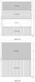
- FIG. 1 is a schematic diagram illustrating an uplink multi-user (MU) transmission according to a non-claimed embodiment.
- MU uplink multi-user
- Multiple HE TB PPDUs transmitted by different STAs at non-overlapping frequency-domain resource and/or spatial domain resource in a 20/40/80/160/320 MHz channel can be treated as a single HE TB PPDU.
- multiple EHT TB PPDUs transmitted by different STAs at non-overlapping frequency-domain resource and/or spatial domain resource in a 20/40/80/160/320 MHz channel can be treated as a single EHT TB PPDU.
- the HE TB PPDUs and EHT TB PPDUs transmitted by all scheduled HE STAs and EHT STAs constitute a TB FD-A-PPDU.
- the AP will transmit a Multi-STA BlockAck (Multi-STA BA) frame in a response to the received TB FD-A-PPDU.
- Multi-STA BA Multi-STA BlockAck
- FIG. 2A is a block diagram illustrating a format of a HE TB PPDU
- Figure 2B is a block diagram illustrating a format of an EHT TB PPDU.
- L-STF Non-HT Short Training Field
- L-LTF Non-HT Long Training Field
- L-SIG Non-HT SIGNAL Field
- R-SIG field Repeated L-SIG field
- HE SIGNAL A field HE-SIG-A field
- HE-SIG-A field HE short Training Field
- HE-LTF HE Long Training field
- PE Packet Extension
- EHT TB PPDU In an EHT TB PPDU, the L-STF, L-LTF, L-SIG field, RL-SIG field and U-SIG field are called pre-EHT modulated fields while the EHT Short Training Field (EHT-STF), EHT Long Training field (EHT-LTF), Data field and PE field are called EHT modulated fields.
- EHT-STF EHT Short Training Field
- EHT-LTF EHT Long Training field
- PE field PE field
- Each HE-LTF or EHT-LTF symbol has the same Guard interval (GI) duration as each data symbol, which is 0.8 ⁇ s, 1.6 ⁇ s or 3.2 ⁇ s.
- the HE-LTF field comprises three types: 1x HE-LTF, 2x HE-LTF and 4x HE-LTF.
- the EHT-LTF field comprises three types: 1x EHT-LTF, 2x EHT-LTF and 4x EHT-LTF.
- the duration of each 1x HE-LTF/EHT-LTF, 2x HE-LTF/EHT-LTF or 4x HE-LTF/EHT-LTF symbol without GI is 3.2 ⁇ s, 6.4 ⁇ s or 12.8 ⁇ s.
- Each data symbol without GI is 12.8 ⁇ s.
- the PE field duration of a HE TB PPDU is 0 ⁇ s, 4 ⁇ s, 8 ⁇ s, 12 ⁇ s or 16 ⁇ s; while the PE field duration of an EHT TB PPDU is 0 ⁇ s, 4 ⁇ s, 8 ⁇ s, 12 ⁇ s, 16 ⁇ s or 20 ⁇ s.
- a TB FD-A-PPDU used for uplink MU transmission may comprise one HE TB PPDU and one or two EHT TB PPDUs if the HE-LTF field has a same symbol duration and a same GI duration as the EHT-LTF field.
- the number of HE-LTF symbols may be the same as or different from the number of EHT-LTF symbols.
- each HE-LTF/EHT-LTF symbol may have a different duration or a same duration from each data symbol.
- each HE-LTF/EHT-LTF symbol without GI may be 6.4 ⁇ s or 12.8 ⁇ s.
- each HE-LTF/EHT-LTF symbol shall have a same duration as each data symbol.
- each HE-LTF/EHT-LTF symbol without GI shall be 12.8 ⁇ s.
- each scheduled HE STA may park in primary 80 MHz channel (P80); while each scheduled EHT STA may park in one of non-primary 80 MHz channel(s) via an enhanced Selective subchannel transmission (SST) mechanism.
- a non-primary 80 MHz channel is an 80 MHz frequency segment outside P80, e.g., secondary 80 MHz channel (S80) in a 160 MHz or 320 MHz channel.
- the BW allocated to HE STAs is P80 while BW allocated to EHT STAs is S80.
- one HE TB PPDU may be transmitted in P80 while one EHT TB PPDU may be transmitted in S80.
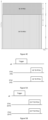
- Figure 3 is 160MHz BW allocation for a TB FD-A-PPDU transmission according to a non-claimed embodiment.
- the BW allocated to HE STAs is P80 or primary 160 MHz channel (P160); while the BW allocated to EHT STAs is one of two 80 MHz frequency segments of secondary 160 MHz channel (S160), S160, a combination of S80 and one of two 80 MHz frequency segments of S160 or a combination of S80 and S160.
- BW FD-A-PPDU For a 320 MHz BW FD-A-PPDU, there may have the following five options for BW allocation in the TB FD-A-PPDU:
- Option 1A When S80 is punctured, BW allocated to HE STAs is P80 and BW allocated to EHT STAs is S160, as illustrated in Figure 4A .
- One HE TB PPDU may be transmitted in P80 while one EHT TB PPDU may be transmitted in S160.
- Option 1B When one of two 80 MHz frequency segments of S160 is punctured, BW allocated to HE STAs is P160 and BW allocated to EHT STAs is the other 80 MHz frequency segment of S160, as illustrated in Figure 4B .
- One HE TB PPDU may be transmitted in P160 while one EHT TB PPDU may be transmitted in the unpunctured 80 MHz frequency segment of S160.
- Option 1C When one of two 80 MHz frequency segments of S160 is punctured, BW allocated to HE STAs is P80 and BW allocated to EHT STAs is S80 and the other 80 MHz frequency segment of S160, as illustrated in Figure 4C .
- One HE TB PPDU may be transmitted in P80 while two EHT TB PPDUs may be transmitted in S80 and the unpunctured 80 MHz frequency segment of S160, respectively.
- Option 1D When none of 80 MHz frequency segments is punctured, BW allocated to HE STAs is P160 and BW allocated to EHT STAs is S160, as illustrated in Figure 4D .
- One HE TB PPDU may be transmitted in P160 while one EHT TB PPDU may be transmitted in S160.
- Option 1E When none of 80 MHz frequency segments is punctured, BW allocated to HE STAs is P80 and BW allocated to EHT STAs is S80 and S160, as illustrated in Figure 4E .
- One HE TB PPDU may be transmitted in P80 while one EHT TB PPDU may be transmitted in S80 and S160.
- a trigger frame can be used to solicit HE TB PPDU transmissions from HE STAs, EHT TB PPDU transmissions from EHT STAs, or TB FD-A-PPDU transmission from both HE STAs and EHT STAs.
- the TB PPDU transmitted by each of scheduled HE STAs is a HE TB PPDU while the TB PPDU transmitted by each of scheduled EHT STAs is a HE TB PPDU or an EHT TB PPDU.
- Figure 5A is a schematic diagram showing an example of a trigger frame soliciting HE TB PPDU transmission from two HE STAs in a WLAN.
- Figure 5B is a schematic diagram showing an example of a trigger frame soliciting EHT TB PPDU transmission from two EHT STAs in a WLAN.
- Figure 5C is a schematic diagram showing an example of a trigger frame soliciting TB FD-A-PPDU transmission from one HE STA and one EHT STA in a WLAN.
- FIG. 6A is a block diagram illustrating a trigger frame format according to one embodiment of the invention.
- the trigger frame format shown in Figure 6A includes a common info field and a user info list field comprising one or more user info fields.
- the formats of the common info field and user info field depend on the type of trigger frame.
- FIG. 6B is a block diagram illustrating an example of a user info field format of trigger frame according to one embodiment of the invention.
- the HE/EHT format subfield of a user info field indicates whether the user info field follows the 802.11ax HE format or the 802.11be EHT format.
- the value of the HE/EHT format subfield of a user info field determines how the remaining subfields of the user info field are interpreted.
- the HE/EHT format subfield of a user info field is set to 0 to indicate the 802.11ax HE format and set to 1 to indicate the 802.11be EHT format.
- the HE/EHT format subfield of a user info field is set to indicate the 802.11ax HE format
- the lower/upper 160 MHz segment subfield is reserved, and the RU allocation subfield indicates a Resource unit (RU) at which a HE TB PPDU is to be transmitted by the STA indicated by the AIDI12 subfield.
- the RU allocation subfield and the lower/upper 160 MHz segment subfield indicate a RU or Multiple resource unit (MRU) at which an EHT TB PPDU is to be transmitted by the STA indicated by the AID12 subfield.
- MRU Multiple resource unit
- Figure 10 is a flowchart illustrating a method 130 for soliciting a TB PPDU transmission in a WLAN implemented by an AP according to some embodiments of the invention.
- the method 130 is implemented by an AP.
- the method 130 may be implemented by any other suitable network interface device.
- a trigger frame is generated by the AP based on a type of PPDU transmissions to be solicited from a plurality of STAs in the WLAN, e.g., HE STAs and/or EHT STAs.
- the type of PPDU transmissions comprises HE TB PPDU transmissions or EHT TB PPDU transmissions, and one or two subfields in the trigger frame, e.g., UL BW subfield, UL BW subfield and Delta EHT UL BW, or UL BW subfield and UL BW Extension subfield, indicate a BW of the solicited TB PPDU.
- the type of PPDU transmissions may comprise FD-A-PPDU transmissions.
- the generated trigger frame is transmitted to the plurality of STAs.
- a common info field of the trigger frame comprises an UL BW subfield indicating a BW of the solicited HE TB PPDU.
- the UL BW subfield occupies 2 bits in the common info field of the trigger frame.
- the BW of the solicited HE TB PPDU is 20 MHz, 40 MHz, 80 MHz or 160/80+80 MHz.
- the BW of the solicited HE TB PPDU indicated by the UL BW subfield in the common info field of the trigger frame is in the HE SIGNAL A (HE SIG-A) field of the solicited HE TB PPDU.
- HE SIGNAL A HE SIG-A
- the common info field of the trigger frame further comprises an enhanced trigger frame flag subfield which indicates whether the trigger frame is an 802.11ax trigger frame or an enhanced trigger frame.
- the enhanced trigger frame includes a common info field and a user info list field comprising one or more user info fields.
- both the UL BW subfield and a Delta EHT UL BW subfield indicate a BW of the solicited EHT TB PPDU.
- the BW of the solicited EHT TB PPDU indicated by both the UL BW subfield and the Delta EHT UL BW subfield is in the universal SIGNAL (U-SIG) field of the solicited EHT TB PPDU.
- U-SIG universal SIGNAL
- the Delta EHT UL BW subfield occupies 2 bits of the enhanced trigger frame.
- the BW of the solicited EHT TB PPDU is 20 MHz, 40 MHz, 80 MHz, 160 MHz or 320 MHz.
- the indicated BW of the solicited EHT TB PPDU is the next available BW larger than the indicated BW of the solicited HE TB PPDU when the BW of the solicited EHT TB PPDU is 40 MHz, 80 MHz, 160 MHz or 320 MHz.
- the indicated BW of the solicited EHT TB PPDU is the next available BW smaller than the indicated BW of the solicited HE TB PPDU when the indicated BW of the solicited EHT TB PPDU is 20MHz, 40 MHz or 80 MHz.
- both the UL BW subfield and a UL BW extension subfield indicate a BW of the solicited EHT TB PPDU.
- the BW of the solicited EHT TB PPDU indicated by both the UL BW subfield and UL BW extension subfield is in the universal SIGNAL (U-SIG) field of the solicited EHT TB PPDU.
- U-SIG universal SIGNAL
- the BW of the solicited EHT TB PPDU is 20 MHz, 40 MHz, 80 MHz, 160 MHz or 320 MHz.
- the indicated BW of the solicited EHT TB PPDU is the next available BW larger than the indicated BW of the solicited HE TB PPDU when the BW of the solicited EHT TB PPDU is 40 MHz, 80 MHz, 160 MHz or 320 MHz.
- the indicated BW of the solicited EHT TB PPDU is the next available BW smaller than the indicated BW of the solicited HE TB PPDU when the indicated BW of the solicited EHT TB PPDU is 20MHz, 40 MHz or 80 MHz.
- FIG 11 is a flowchart illustrating a method 140 for soliciting a TB PPDU transmission in a WLAN implemented by a STA according to some embodiments of the invention.
- the method 140 is implemented by a STA.
- the method 140 may be implemented by any other suitable client device.
- a trigger frame from an AP is received by a STA, e.g., a HE STA and/or an EHT STA, the trigger frame is generated based on a type of PPDU transmissions to be solicited from a plurality of STAs, e.g., HE STAs and/or EHT STAs.
- the type of PPDU transmissions comprises HE TB PPDU transmissions or EHT TB PPDU transmissions, and one or two subfields in the trigger frame, e.g., UL BW subfield, UL BW subfield and Delta EHT UL BW, or UL BW subfield and UL BW Extension subfield, indicate a BW of the solicited TB PPDU.
- the type of PPDU transmissions may comprise FD-A-PPDU transmissions.
- the solicited TB PPDU in the BW indicated by the one or two subfields in the trigger frame is transmitted by the STA.
- a common info field of the trigger frame comprises an UL BW subfield indicating a BW of the solicited HE TB PPDU.
- the UL BW subfield occupies 2 bits in the common info field of the trigger frame.
- the BW of the solicited HE TB PPDU is 20 MHz, 40 MHz, 80 MHz or 160/80+80 MHz.
- the BW of the solicited HE TB PPDU indicated by the UL BW subfield in the common info field of the trigger frame is in the HE SIGNAL A (HE SIG-A) field of the solicited HE TB PPDU.
- HE SIGNAL A HE SIG-A
- the common info field of the trigger frame further comprises an enhanced trigger frame flag subfield which indicates whether the trigger frame is an 802.11ax trigger frame or an enhanced trigger frame.
- the enhanced trigger frame includes a common info field and a user info list field comprising one or more user info fields.
- both the UL BW subfield and a Delta EHT UL BW subfield indicate a BW of the solicited EHT TB PPDU.
- the BW of the solicited EHT TB PPDU indicated by both the UL BW subfield and the Delta EHT UL BW subfield is in the universal SIGNAL (U-SIG) field of the solicited EHT TB PPDU.
- U-SIG universal SIGNAL
- the Delta EHT UL BW subfield occupies 2 bits of the enhanced trigger frame.
- the BW of the solicited EHT TB PPDU is 20 MHz, 40 MHz, 80 MHz, 160 MHz or 320 MHz.
- the indicated BW of the solicited EHT TB PPDU is the same as the indicated BW of the solicited HE TB PPDU when the indicated BW of the solicited EHT TB PPDU is 20 MHz, 40MHz, 80 MHz or160 MHz.
- the indicated BW of the solicited EHT TB PPDU is the next available BW larger than the indicated BW of the solicited HE TB PPDU when the BW of the solicited EHT TB PPDU is 40 MHz, 80 MHz, 160 MHz or 320 MHz.
- the indicated BW of the solicited EHT TB PPDU is the next available BW smaller than the indicated BW of the solicited HE TB PPDU when the indicated BW of the solicited EHT TB PPDU is 20MHz, 40 MHz or 80 MHz.
- both the UL BW subfield and a UL BW extension subfield indicate a BW of the solicited EHT TB PPDU.
- the BW of the solicited EHT TB PPDU indicated by both the UL BW subfield and UL BW extension subfield is in the universal SIGNAL (U-SIG) field of the solicited EHT TB PPDU.
- U-SIG universal SIGNAL
- the BW of the solicited EHT TB PPDU is 20 MHz, 40 MHz, 80 MHz, 160 MHz or 320 MHz.
- the indicated BW of the solicited EHT TB PPDU is the same as the indicated BW of the solicited HE TB PPDU when the indicated BW of the solicited EHT TB PPDU is 20 MHz, 40MHz, 80 MHz or160 MHz.
- the indicated BW of the solicited EHT TB PPDU is the next available BW larger than the indicated BW of the solicited HE TB PPDU when the BW of the solicited EHT TB PPDU is 40 MHz, 80 MHz, 160 MHz or 320 MHz.
- the indicated BW of the solicited EHT TB PPDU is the next available BW smaller than the indicated BW of the solicited HE TB PPDU when the indicated BW of the solicited EHT TB PPDU is 20MHz, 40 MHz or 80 MHz.
- FIG 12A is a schematic diagram illustrating an AP 1500A for soliciting a TB PPDU transmission in a WLAN according to one embodiment of the invention.
- the AP 1500A includes a generation unit 1501a and a first transmission unit 1502b.
- the generation unit 1501a is configured to generate a trigger frame based on a type of TB PPDU transmissions to be solicited from a plurality of STAs in the WLAN, e.g., HE STAs and/or EHT STAs.
- the type of TB PPDU transmissions comprises HE TB PPDU transmissions or EHT TB PPDU transmissions, and one or two subfields, e.g., UL BW subfield, UL BW subfield and Delta EHT UL BW, or UL BW subfield and UL BW Extension subfield, in the trigger frame indicate a BW of the solicited TB PPDU.
- the type of PPDU transmissions may comprise FD-A-PPDU transmissions.
- the first transmission unit 1502b is configured to transmit the solicited TB PPDU in the BW indicated by the one or two subfields in the trigger frame.
- FIG 12B is a schematic diagram illustrating an AP 1500B for soliciting a TB PPDU transmission in a WLAN according to one embodiment of the invention.
- the AP 1500B includes a memory 1501b configured to store instructions for soliciting a TB PPDU transmission in a WLAN, and a processor 1502b communicably coupled with the memory, the processor 1502b configured to execute the instructions to cause the AP 1500B to perform the method for soliciting a TB PPDU transmission in a WLAN according to some embodiments of the invention, e.g., the method described above and illustrated in Figure 10 .
- FIG. 13A is a schematic diagram illustrating a STA 1600A for soliciting a TB PPDU transmission in a WLAN according to one embodiment of the invention.
- the STA 1600A includes a reception unit 1601a and a second transmission unit 1602b.
- the reception unit 1601a is configured to receive a trigger frame which is used to solicit a type of TB PPDU transmissions from a plurality of STAs in the WLAN, e.g., HE STAs and/or EHT STAs.
- the type of TB PPDU transmissions comprises HE TB PPDU transmissions or EHT TB PPDU transmissions, and one or two subfields, e.g., UL BW subfield, UL BW subfield and Delta EHT UL BW, or UL BW subfield and UL BW Extension subfield, in the trigger frame indicate a bandwidth (BW) of the solicited TB PPDU.
- the type of PPDU transmissions may comprise FD-A-PPDU transmissions.
- the second transmission unit 1602b is configured to transmit the solicited TB PPDU in the BW indicated by the one or two subfields in the trigger frame.
- FIG. 13B is a schematic diagram illustrating a STA 1600B for soliciting a TB PPDU transmission in a WLAN according to one embodiment of the invention.
- the STA 1600B includes a memory 1601b configured to store instructions for soliciting a TB PPDU transmission in a WLAN, and a processor 1602b communicably coupled with the memory, the processor 1602b configured to execute the instructions to cause the STA 1600B to perform the method for soliciting a TB PPDU transmission in a WLAN according to some embodiments of the invention, e.g., the method described above and illustrated in Figure 11 .
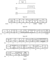
- FIG. 7 is a block diagram illustrating an example of the common info field format of trigger frame according to the first embodiment.
- the enhanced trigger frame flag subfield indicates whether the trigger frame is an 802.11ax trigger frame or an enhanced trigger frame.
- the enhanced trigger frame flag subfield is set to 0 to indicate an 802.11ax trigger frame; and set to 1 to indicate an enhanced trigger frame.
- the UL BW Extension subfield is reserved, and the UL BW subfield indicates the BW in the HE-SIG-A field of the solicited HE TB PPDU which is 20 MHz, 40 MHz, 80 MHz or 160/80+80 MHz.
- both the UL BW subfield and the UL BW extension subfield indicate the BW in the U-SIG of the solicited EHT TB PPDU which is 20 MHz, 40 MHz, 80 MHz, 160 MHz or 320 MHz.
- the trigger frame with the common info field shown in Figure 7 can be used to solicit HE TB PPDU transmission from HE STAs or EHT TB PPDU transmission from EHT STAs.
- the enhanced trigger frame flag subfield of the common info field is set to indicate an 802.11ax trigger frame and the UL BW subfield is set to indicate 160/80+80 MHz BW.
- the enhanced trigger frame flag subfield is set to indicate an enhanced trigger frame
- both the UL BW subfield and UL BW extension subfield are set to indicate 320 MHz BW.
- the trigger frame with the common info field shown in Figure 7 can also be used to solicit TB FD-A-PPDU transmission from both HE STAs and EHT STAs where the solicited TB FD-A-PPDU comprises one HE TB PPDU and one or two EHT TB PPDUs.
- the enhanced trigger frame flag subfield is set to indicate an enhanced trigger frame
- the UL BW extension subfield is set to 0 and the UL BW subfield indicates the BW in the HE-SIG-A field of the one HE TB PPDU which is the same as the BW in the U-SIG fields of the one or two EHT TB PPDUs.
- the UL BW subfield of the common info field of the trigger frame may be set to indicate a half of the BW of the solicited TB FD-A-PPDU. For one example, when the trigger frame is used to solicit 160 MHz BW TB FD-A-PPDU transmission, the UL BW subfield is set to indicate 80 MHz. For another example, when the trigger frame is used to solicit 320 MHz BW TB FD-A-PPDU transmission, the UL BW subfield is set to indicate 160 MHz.
- BW allocation option 1A, 1B or 1E for 320 MHz BW TB FD-A-PPDU comprising one HE TB PPDU and one or two EHT TB PPDUs
- the BW in the HE-SIG-A field of the one HE TB PPDU is not the same as its allocated BW
- the BW in the U-SIG fields of the one or two EHT TB PPDUs is not the same as their respective allocated BW.
- FIG. 8 is a block diagram illustrating an example of the common info field format of trigger frame according to the second embodiment.
- the enhanced trigger frame flag subfield is used to indicate whether the trigger frame is an 802.11ax trigger frame or an enhanced trigger frame.
- the enhanced trigger frame flag subfield is set to 0 to indicate an 802.11ax trigger frame; and set to 1 to indicate an enhanced trigger frame.
- the EHT UL BW subfield is reserved, and the UL BW subfield indicates the BW in the HE-SIG-A field of the solicited HE TB PPDU.
- the UL BW subfield indicates the BW in the HE-SIG-A field of the one HE TB PPDU in the solicited TB FD-A-PPDU
- the EHT UL BW subfield indicates the BW in the U-SIG field of the solicited EHT TB PPDU or the U-SIG fields of the one or two EHT TB PPDUs in the solicited TB FD-A-PPDU.
- the trigger frame with the common info field shown in Figure 8 can be used to solicit HE TB PPDU transmission from HE STAs, EHT TB PPDU transmission from EHT STAs, or TB FD-A-PPDU transmission from both HE STAs and EHT STAs.
- the trigger frame when the trigger frame is used to solicit 160 MHz HE TB PPDU transmission from HE STAs, the enhanced trigger frame flag subfield is set to indicate an 802.11ax trigger frame and the UL BW subfield is set to indicate 160/80+80 MHz BW.
- the enhanced trigger frame flag subfield is set to indicate an enhanced trigger frame and the EHT UL BW subfield is set to indicate 320 MHz BW.
- the trigger frame is used to solicit FD-A-PPDU transmission from both HE STAs and EHT STAs
- the enhanced trigger frame flag subfield is set to indicate an enhanced trigger frame
- the values of both UL BW subfield and EHT UL BW subfield are set according to the BW and BW allocation of the solicited TB FD-A-PPDU as shown in Table 9.
- Table 9 Settings of UL BW subfield and EHT UL BW subfield when the trigger frame is used to solicit FD-A-PPDU transmission according to the second embodiment FD-A-PPDU BW BW Allocation Option UL BW subfield indication EHT UL BW subfield indication 160 MHz 80 MHz 80 MHz 320 MHz 1A 80 MHz 160 MHz 1B 160 MHz 80 MHz 1C 80 MHz 80 MHz 1D 160 MHz 160 MHz 1E 80 MHz 320 MHz
- BW allocation option 1A for 320 MHz BW TB FD-A-PPDU, the BW allocated to one HE TB PPDU is 80 MHz and the BW allocated to one EHT TB PPDU is 160 MHz.
- the UL BW subfield is set to indicate 80 MHz BW for the HE TB PPDU and the EHT UL BW subfield is set to indicate 160 MHz BW for the EHT TB PPDU.
- BW allocation option 1B for 320 MHz BW TB FD-A-PPDU the BW allocated to one HE TB PPDU is 160 MHz and the BW allocated to one EHT TB PPDU is 80 MHz.
- the UL BW subfield is set to indicate 160 MHz BW for the HE TB PPDU and the EHT UL BW subfield is set to indicate 80 MHz BW for the EHT TB PPDU.
- BW allocation option 1C for 320 MHz BW TB FD-A-PPDU
- the BW allocated to one HE TB PPDU is 80 MHz
- the BW allocated to each of two EHT TB PPDUs is 80 MHz.
- the UL BW subfield is set to indicate 80 MHz BW for the HE TB PPDU
- the EHT UL BW subfield is set to indicate 80 MHz BW for each of the two EHT TB PPDUs.
- BW allocation option 1D for 320 MHz BW TB FD-A-PPDU, the BW allocated to one HE TB PPDU is 160 MHz and the BW allocated to one EHT TB PPDU is 160 MHz.
- both the UL BW subfield and the EHT UL BW subfield are set to indicate 160 MHz BW.
- BW allocation option 1E for 320 MHz BW TB FD-A-PPDU, the BW allocated to one HE TB PPDU is 80 MHz and the BW allocated to one EHT TB PPDU is 240 MHz.
- the UL BW subfield is set to indicate 80 MHz BW for the HE TB PPDU and the EHT UL BW subfield is set to indicate 320 MHz BW since there is no 240 MHz EHT TB PPDU and 240 MHz transmission is obtained by puncturing an 80 MHz frequency segment from 320 MHz EHT TB PPDU.
- the BW in the HE-SIG-A field of the one HE TB PPDU is the same as its allocated BW and the BW in the U-SIG fields of the one or two EHT TB PPDUs is the same as their respective allocated BW.
- FIG. 9 is a block diagram illustrating an example of the common info field format of trigger frame according to the third embodiment.
- the enhanced trigger frame flag subfield is used to indicate whether the trigger frame is an 802.11ax trigger frame or an enhanced trigger frame.
- the enhanced trigger frame flag subfield is set to 0 to indicate an 802.11ax trigger frame; and set to 1 to indicate an enhanced trigger frame.
- the Delta EHT UL BW subfield is reserved, and the UL BW subfield indicates the BW in the HE-SIG-A field of the solicited HE TB PPDU.
- the UL BW subfield indicates the BW in the HE-SIG-A field of the one HE TB PPDU in the solicited TB FD-A-PPDU
- both the Delta EHT UL BW subfield and the UL BW subfield indicate the BW in the U-SIG field of the solicited EHT TB PPDU or the U-SIG fields of the one or two EHT TB PPDUs in the solicited TB FD-A-PPDU.
- the Delta EHT UL BW subfield is set to 0 to indicate the BW in the U-SIG field of the solicited EHT TB PPDU or the U-SIG fields of the one or two EHT TB PPDUs in the solicited TB FD-A-PPDU is the same as the BW indicated in the UL BW subfield.
- the BW in the U-SIG field of the solicited EHT TB PPDU and the BW in the U-SIG fields of the one or two EHT TB PPDUs in the solicited TB FD-A-PPDU could be 20MHz or 40MHz or 80MHz or 160MHz.
- the Delta EHT UL BW subfield is set to 1 to indicate the BW in the U-SIG field of the solicited EHT TB PPDU or the U-SIG fields of the one or two EHT TB PPDUs in the solicited TB FD-A-PPDU is the next available BW larger than the BW indicated in the UL BW subfield.
- the Delta EHT UL BW subfield is set to 2 to indicate the BW in the U-SIG field of the solicited EHT TB PPDU or the U-SIG fields of the one or two EHT TB PPDUs in the solicited TB FD-A-PPDU is the second next available BW larger than the BW indicated in the UL BW subfield.
- the Delta EHT UL BW subfield is set to 3 to indicate the BW in the U-SIG field of the solicited EHT TB PPDU or the U-SIG fields of the one or two EHT TB PPDUs in the solicited TB FD-A-PPDU is the next available BW smaller than the BW indicated in the UL BW subfield. For example, when the UL BW subfield is set to indicate 80 MHz BW and the Delta EHT UL BW subfield is set to 0, the BW in the U-SIG field of the solicited EHT TB PPDU or the U-SIG fields of the one or two EHT TB PPDUs in the solicited TB FD-A-PPDU is 80 MHz.
- the BW in the U-SIG field of the solicited EHT TB PPDU or the U-SIG fields of the one or two EHT TB PPDUs in the solicited TB FD-A-PPDU is 160 MHz.
- the UL BW subfield is set to indicate 80 MHz BW and the Delta EHT UL BW subfield is set to 2
- the BW in the U-SIG field of the solicited EHT TB PPDU or the U-SIG fields of the one or two EHT TB PPDUs in the solicited TB FD-A-PPDU is 320 MHz.
- the UL BW subfield When the UL BW subfield is set to indicate 160 MHz BW and the Delta EHT UL BW subfield is set to 3, the BW in the U-SIG field of the solicited EHT TB PPDU or the U-SIG fields of the one or two EHT TB PPDUs in the solicited TB FD-A-PPDU is 80 MHz.
- the valid combinations of the UL BW subfield indication and the Delta EHT UL BW subfield value are shown in Table 11.
- Table 11 Valid combinations of the UL BW subfield indication and the Delta EHT UL BW subfield value according to the third embodiment UL BW subfield indication Delta EHT UL BW subfield value BW in U-SIG of EHT TB PPDU 20/40/80/160 MHz 0 20/40/80/160 MHz 20 MHz 1 40 MHz 20 MHz 2 80 MHz 40 MHz 1 80 MHz 40 MHz 2 160 MHz 40 MHz 3 20 MHz 80 MHz 1 160 MHz 80 MHz 2 320 MHz 80 MHz 3 40 MHz 160 MHz 1 320 MHz 160 MHz 3 80 MHz
- the UL BW subfield indicates the BW in the HE-SIG-A.
- the trigger frame with the common info field shown in Figure 9 can be used to solicit HE TB PPDU transmission from HE STAs, EHT TB PPDU transmission from EHT STAs, or TB FD-A-PPDU transmission from both HE STAs and EHT STAs.
- the TB PPDU transmitted by each of scheduled HE STAs is a HE TB PPDU while the TB PPDU transmitted by each of scheduled EHT STAs is a HE TB PPDU or an EHT TB PPDU.
- the enhanced trigger frame flag subfield is set to indicate an 802.11ax trigger frame and the UL BW subfield is set to indicate 160/80+80 MHz BW.
- the enhanced trigger frame flag subfield is set to indicate an enhanced trigger frame
- the UL BW subfield is set to indicate 80 MHz BW
- the Delta EHT UL BW subfield is set to 2.
- the enhanced trigger frame flag subfield is set to indicate an enhanced trigger frame
- the UL BW subfield and Delta EHT UL BW subfield are set according to the FD-A-PPDU's BW and BW allocation option as shown in Table 12.
- Table 12 Settings of UL BW subfield and Delta EHT UL BW subfield when the trigger frame is used to solicit FD-A-PPDU transmission according to the third embodiment FD-A-PPDU BW BW Allocation Option UL BW subfield indication Delta EHT UL BW subfield value 160 MHz 80 MHz 0 320 MHz 1A 80 MHz 1 1B 160 MHz 3 1C 80 MHz 0 1D 160 MHz 0 1E 80 MHz 2
- BW allocation option 1A for 320 MHz BW TB FD-A-PPDU, the BW allocated to one HE TB PPDU is 80 MHz and the BW allocated to one EHT TB PPDU is 160 MHz.
- the UL BW subfield is set to indicate 80 MHz BW and the Delta EHT UL BW subfield is set to 1.
- BW allocation option 1B for 320 MHz BW TB FD-A-PPDU the BW allocated to one HE TB PPDU is 160 MHz and the BW allocated to one EHT TB PPDU is 80 MHz.
- the UL BW subfield is set to indicate 160 MHz BW and the Delta EHT UL BW subfield is set to 3.
- the BW allocated to one HE TB PPDU is 80 MHz and the BW allocated to each of two EHT TB PPDUs is 80 MHz.
- the UL BW subfield is set to indicate 80 MHz BW and the Delta EHT UL BW subfield is set to 0.
- BW allocation option 1D for 320 MHz BW TB FD-A-PPDU, the BW allocated to one HE TB PPDU is 160 MHz and the BW allocated to one EHT TB PPDU is 160 MHz.
- the UL BW subfield is set to indicate 160 MHz BW and the Delta EHT UL BW subfield is set to 0.
- BW allocation option 1E for 320 MHz BW TB FD-A-PPDU, the BW allocated to one HE TB PPDU is 80 MHz and the BW allocated to one EHT TB PPDU is 240 MHz.
- the UL BW subfield is set to indicate 80 MHz BW and the Delta EHT UL BW subfield is set to 2 since there is no 240 MHz EHT TB PPDU and 240 MHz transmission is obtained by puncturing an 80 MHz frequency segment from 320 MHz EHT TB PPDU.
- the BW in the HE-SIG-A field of the one HE TB PPDU is the same as its allocated BW and the BW in the U-SIG fields of the one or two EHT TB PPDUs is the same as their respective allocated BW.
- the common info field of the trigger frame comprises a UL BW subfield and a subfield.
- the UL BW subfield indicates the BW in the HE-SIG-A field of the one HE TB PPDU, which is the same as the BW in the U-SIG fields of the one or two EHT TB PPDUs; and the BW indicated in the UL BW subfield may be equal to a half of the BW of the solicited TB FD-A-PPDU.
- both the UL BW subfield and the subfield indicate the BW in the HE-SIG-A field of the solicited EHT TB PPDU.
- the UL BW subfield indicates the BW in the HE-SIG-A field of the one HE TB PPDU in the solicited TB FD-A-PPDU and the subfield indicates the BW in the U-SIG fields of the one or two EHT TB PPDUs in the solicited TB FD-A-PPDU or the U-SIG field of the solicited EHT TB PPDU.
- the values of the UL BW subfield and the subfield may be set according to the BW and BW allocation of the solicited TB FD-A-PPDU.
- the UL BW subfield indicates the BW in the HE-SIG-A field of the one HE TB PPDU in the solicited TB FD-A-PPDU, and both the UL BW subfield and the subfield indicate the BW in the U-SIG fields of the one or two EHT TB PPDUs in the solicited TB FD-A-PPDU or the U-SIG field of the solicited EHT TB PPDU.
- Various embodiments of the present disclosure also provide a computer program product comprising instructions to cause a computer to perform a method for soliciting a TB PPDU transmission in a WLAN according to any embodiment of the invention, when executed thereon.
- Various embodiments of the present disclosure also provide a computer program comprising instructions to cause a computer to perform a method for soliciting a TB PPDU transmission in a WLAN according to any embodiment of the invention, when executed thereon.
- Various embodiments of the present disclosure also provide a non-volatile storage medium comprising computer program codes to cause a computer to perform a method for soliciting a TB PPDU transmission in a WLAN according to any embodiment of the invention, when executed thereon.
- Various embodiments of the present disclosure also provide a chip configured to perform a method for soliciting a TB PPDU transmission in a WLAN according to any embodiment of the invention, when executed thereon.
Landscapes
- Engineering & Computer Science (AREA)
- Signal Processing (AREA)
- Computer Networks & Wireless Communication (AREA)
- Mobile Radio Communication Systems (AREA)
- Communication Control (AREA)
Claims (15)
- Verfahren zur Anforderung einer triggerbasierten (TB) physischen Schichtprotokolldateneinheit- bzw. PPDU-Übertragung in einem drahtlosen lokalen Netzwerk, WLAN, wobei das Verfahren Folgendes umfasst:Empfangen (1401), durch eine Station, STA, eines Triggerframes, der verwendet wird zum Anfordern eines Typs von TB-PPDU-Übertragungen von mehreren STAs im WLAN, wobei der Typ von TB-PPDU-Übertragungen hocheffiziente (HE), triggerbasierte (TB) PPDU-Übertragungen oder TB-PPDU-Übertragungen mit extrem hohem Durchsatz (EHT) umfasst und wobei ein oder zwei Teilfelder im Triggerframe eine Bandbreite (BW) der angeforderten TB PPDU anzeigen, undSenden (1402), durch die STA, der angeforderten TB PPDU in der durch das eine oder die zwei Teilfelder im Triggerframe angezeigten BW;wobei ein allgemeines Info-Feld des Triggerframes ein Uplink(UL)-Bandbreiten(BW)-Teilfeld umfasst, das eine BW der angeforderten HE TB PPDU anzeigt;wobei das allgemeine Info-Feld des Triggerframes ferner ein erweitertes Triggerframe-Kennzeichen-Teilfeld umfasst, das anzeigt, ob der Triggerframe ein 802.11ax-Triggerframe oder ein erweiterter Triggerframe ist;dadurch gekennzeichnet, dass, wenn das erweiterte Triggerframe-Kennzeichen-Teilfeld anzeigt, dass der Triggerframe ein erweiterter Triggerframe ist, sowohl das UL-BW-Teilfeld als auch ein Delta-EHT-UL-BW-Teilfeld eine BW der angeforderten EHT TB PPDU anzeigen;wobei das UL-BW-Teilfeld 2 Bits im allgemeinen Info-Feld des Triggerframes belegt und das Delta-EHT-UL-BW-Teilfeld 2 Bits des erweiterten Triggerframes belegt.
- Verfahren nach Anspruch 1, wobei die BW der angeforderten HE TB PPDU, die durch das UL-BW-Teilfeld im allgemeinen Info-Feld des Triggerframes angezeigt wird, im HE-SIGNAL-A- bzw. HE-SIG-A-Feld der angeforderten HE TB PPDU ist.
- Verfahren nach Anspruch 1, wobei die BW der angeforderten EHT TB PPDU, die sowohl durch das UL-BW-Teilfeld als auch das Delta-EHT-UL-BW-Teilfeld angezeigt wird, im universellen SIGNAL- bzw. U-SIG-Feld der angeforderten EHT TB PPDU ist.
- Verfahren nach Anspruch 1 oder 3, wobei die BW der angeforderten EHT TB PPDU 20 MHz, 40 MHz, 80 MHz, 160 MHz oder 320 MHz ist.
- Verfahren nach einem der Ansprüche 1 oder 3 bis 4, wobei die angezeigte BW der angeforderten EHT TB PPDU die gleiche wie die angezeigte BW der angeforderten HE TB PPDU ist, wenn die angezeigte BW der angeforderten EHT TB PPDU 20 MHz, 40 MHz, 80 MHz oder 160 MHz ist.
- Verfahren nach einem der Ansprüche 1 oder 3 bis 4, wobei die angezeigte BW der angeforderten EHT TB PPDU die nächste verfügbare BW ist, die größer als die angezeigte BW der angeforderten HE TB PPDU ist, wenn die angezeigte BW der angeforderten EHT TB PPDU 320 MHz ist.
- Verfahren nach einem der Ansprüche 1 oder 3 bis 4, wobei die angezeigte BW der angeforderten EHT TB PPDU die nächste verfügbare BW ist, die kleiner als die angezeigte BW der angeforderten HE TB PPDU ist, wenn die angezeigte BW der angeforderten EHT TB PPDU 80 MHz ist.
- Verfahren nach einem der Ansprüche 1 und 3 bis 7, wobei der erweiterte Triggerframe ein allgemeines Info-Feld und ein Benutzerinfolistenfeld, umfassend ein oder mehrere Benutzerinfofelder, umfasst.
- Verfahren nach einem der Ansprüche 1 bis 8, wobei die BW der angeforderten HE TB PPDU 20 MHz, 40 MHz, 80 MHz oder 160/80+80 MHz ist.
- Verfahren nach einem der Ansprüche 1 bis 9, wobei die mehreren STAs HE-STAs und/oder EHT-STAs umfassen.
- Station, STA, wobei die STA ausgelegt ist zum Durchführen des Verfahrens nach einem der Ansprüche 1 bis 10.
- Verfahren zur Anforderung einer triggerbasierten (TB) physischen Schichtprotokolldateneinheit- bzw. PPDU-Übertragung in einem drahtlosen lokalen Netzwerk, WLAN, wobei das Verfahren Folgendes umfasst:Erzeugen (1301), durch einen Zugangspunkt, AP, eines Triggerframes, der verwendet wird zum Anfordern eines Typs von TB-PPDU-Übertragungen von mehreren STAs im WLAN, wobei ein Typ von TB-PPDU-Übertragungen hocheffiziente (HE), triggerbasierte (TB) PPDU-Übertragungen oder TB-PPDU-Übertragungen mit extrem hohem Durchsatz (EHT) umfasst und wobei ein oder zwei Teilfelder im Triggerframe eine Bandbreite (BW) der angeforderten TB PPDU anzeigen, undSenden (1302), durch die AP, der angeforderten TB PPDU in der durch das eine oder die zwei Teilfelder im Triggerframe angezeigten BW;wobei ein allgemeines Info-Feld des Triggerframes ein Uplink(UL)-Bandbreiten(BW)-Teilfeld umfasst, das eine BW der angeforderten HE TB PPDU anzeigt;wobei das allgemeine Info-Feld des Triggerframes ferner ein erweitertes Triggerframe-Kennzeichen-Teilfeld umfasst, das anzeigt, ob der Triggerframe ein 802.11ax-Triggerframe oder ein erweiterter Triggerframe ist;dadurch gekennzeichnet, dass, wenn das erweiterte Triggerframe-Kennzeichen-Teilfeld anzeigt, dass der Triggerframe ein erweiterter Triggerframe ist, sowohl das UL-BW-Teilfeld als auch ein Delta-EHT-UL-BW-Teilfeld eine BW der angeforderten EHT TB PPDU anzeigen;wobei das UL-BW-Teilfeld 2 Bits im allgemeinen Info-Feld des Triggerframes belegt und das Delta-EHT-UL-BW-Teilfeld 2 Bits des erweiterten Triggerframes belegt.
- Verfahren nach Anspruch 12, wobei die BW der angeforderten EHT TB PPDU 20 MHz, 40 MHz, 80 MHz, 160 MHz oder 320 MHz ist.
- Verfahren nach einem der Ansprüche 12 oder 13, wobei die angezeigte BW der angeforderten EHT TB PPDU die gleiche wie die angezeigte BW der angeforderten HE TB PPDU ist, wenn die angezeigte BW der angeforderten EHT TB PPDU 20 MHz, 40 MHz, 80 MHz oder 160 MHz ist.
- Zugangspunkt, AP, zum Anfordern einer triggerbasierten (TB) physischen Schichtprotokolldateneinheit, PPDU, in einem drahtlosen lokalen Netzwerk, WLAN, wobei der AP ausgelegt ist zum Durchführen des Verfahrens nach einem der Ansprüche 12 bis 14.
Priority Applications (1)
| Application Number | Priority Date | Filing Date | Title |
|---|---|---|---|
| EP25168974.1A EP4580308A3 (de) | 2020-12-02 | 2021-12-02 | Verfahren und vorrichtungen zur anforderung einer triggerbasierten physikalischen schichtprotokolldatenübertragung in einem drahtlosen lokalen netzwerk |
Applications Claiming Priority (2)
| Application Number | Priority Date | Filing Date | Title |
|---|---|---|---|
| SG10202012038U | 2020-12-02 | ||
| PCT/CN2021/135181 WO2022117057A1 (en) | 2020-12-02 | 2021-12-02 | Methods and apparatuses for soliciting trigger-based physical layer protocol data unit transmission in wireless local area network |
Related Child Applications (2)
| Application Number | Title | Priority Date | Filing Date |
|---|---|---|---|
| EP25168974.1A Division-Into EP4580308A3 (de) | 2020-12-02 | 2021-12-02 | Verfahren und vorrichtungen zur anforderung einer triggerbasierten physikalischen schichtprotokolldatenübertragung in einem drahtlosen lokalen netzwerk |
| EP25168974.1A Division EP4580308A3 (de) | 2020-12-02 | 2021-12-02 | Verfahren und vorrichtungen zur anforderung einer triggerbasierten physikalischen schichtprotokolldatenübertragung in einem drahtlosen lokalen netzwerk |
Publications (3)
| Publication Number | Publication Date |
|---|---|
| EP4229998A1 EP4229998A1 (de) | 2023-08-23 |
| EP4229998A4 EP4229998A4 (de) | 2024-04-10 |
| EP4229998B1 true EP4229998B1 (de) | 2025-05-21 |
Family
ID=81853826
Family Applications (2)
| Application Number | Title | Priority Date | Filing Date |
|---|---|---|---|
| EP25168974.1A Pending EP4580308A3 (de) | 2020-12-02 | 2021-12-02 | Verfahren und vorrichtungen zur anforderung einer triggerbasierten physikalischen schichtprotokolldatenübertragung in einem drahtlosen lokalen netzwerk |
| EP21900083.3A Active EP4229998B1 (de) | 2020-12-02 | 2021-12-02 | Verfahren und vorrichtungen zur anforderung einer triggerbasierten physikalischen schichtprotokolldatenübertragung in einem drahtlosen lokalen netzwerk |
Family Applications Before (1)
| Application Number | Title | Priority Date | Filing Date |
|---|---|---|---|
| EP25168974.1A Pending EP4580308A3 (de) | 2020-12-02 | 2021-12-02 | Verfahren und vorrichtungen zur anforderung einer triggerbasierten physikalischen schichtprotokolldatenübertragung in einem drahtlosen lokalen netzwerk |
Country Status (9)
| Country | Link |
|---|---|
| US (1) | US12588018B2 (de) |
| EP (2) | EP4580308A3 (de) |
| JP (1) | JP2023551492A (de) |
| KR (1) | KR20230113332A (de) |
| CN (2) | CN117202366B (de) |
| AU (1) | AU2021393650B2 (de) |
| CA (1) | CA3199708A1 (de) |
| ES (1) | ES3032877T3 (de) |
| WO (1) | WO2022117057A1 (de) |
Families Citing this family (5)
| Publication number | Priority date | Publication date | Assignee | Title |
|---|---|---|---|---|
| KR20230118581A (ko) * | 2020-12-17 | 2023-08-11 | 엘지전자 주식회사 | 무선랜 시스템에서 appdu를 생성하는 방법 및 장치 |
| CN114845395A (zh) * | 2021-02-02 | 2022-08-02 | 华为技术有限公司 | 一种通信方法及装置 |
| EP4732491A1 (de) * | 2023-06-26 | 2026-04-29 | Qualcomm Incorporated | Techniken für die übertragung von 48- und 40 mhz bei wifi |
| WO2026000380A1 (zh) * | 2024-06-28 | 2026-01-02 | Oppo广东移动通信有限公司 | 无线通信方法以及通信设备 |
| WO2026010209A1 (ko) * | 2024-07-05 | 2026-01-08 | 엘지전자 주식회사 | 무선랜 시스템에서 트리거 프레임을 기반으로 elr ppdu를 송신하는 방법 및 장치 |
Family Cites Families (33)
| Publication number | Priority date | Publication date | Assignee | Title |
|---|---|---|---|---|
| US10582025B2 (en) * | 2015-05-05 | 2020-03-03 | Samsung Electronics Co., Ltd. | Efficient signaling and addressing in wireless local area network systems |
| US10560962B2 (en) * | 2015-07-29 | 2020-02-11 | Lg Electronics Inc. | Method and apparatus for transmitting data in wireless communication system |
| WO2017030342A1 (ko) * | 2015-08-19 | 2017-02-23 | 엘지전자(주) | 무선 통신 시스템에서 트리거 프레임 전송 방법 및 이를 위한 장치 |
| TWI710272B (zh) * | 2015-09-11 | 2020-11-11 | 美商內數位專利控股公司 | 無線區域網路(wlan)多使用者同時隨機存取方法及裝置 |
| US10420121B2 (en) * | 2015-11-03 | 2019-09-17 | Newracom, Inc. | Aggregated HE control content in A-MPDU |
| US10375683B2 (en) | 2016-05-06 | 2019-08-06 | Qualcomm Incorporated | Trigger frame in wireless local area network |
| US10397955B2 (en) * | 2016-07-06 | 2019-08-27 | Frontside | Uplink PPDU transmission |
| EP3488659B8 (de) * | 2016-07-22 | 2023-03-08 | Panasonic Intellectual Property Corporation of America | Übertragungsvorrichtung und übertragungsverfahren |
| US20180062805A1 (en) | 2016-08-25 | 2018-03-01 | Po-Kai Huang | Setting of spatial reuse field for he trigger-based ppdu |
| US10412764B2 (en) * | 2016-09-28 | 2019-09-10 | Frontside | Multiple frame transmission |
| US10575249B2 (en) * | 2016-11-22 | 2020-02-25 | Frontside | Transmitting PPDU |
| CN114745805B (zh) | 2016-12-27 | 2025-05-30 | 韦勒斯标准与技术协会公司 | 使用ofdm随机接入的无线通信方法和无线通信终端 |
| US10749996B2 (en) * | 2017-05-26 | 2020-08-18 | Newracom, Inc. | Doppler mode in a wireless network |
| US11109278B2 (en) * | 2017-10-20 | 2021-08-31 | Qualcomm Incorporated | Multiplexing clients of different generations in trigger-based transmissions |
| CN114745802A (zh) * | 2017-12-29 | 2022-07-12 | 华为技术有限公司 | 无线局域网中多信道混合传输方法和装置 |
| CN110380746B (zh) | 2018-03-12 | 2021-08-31 | 苏州速通半导体科技有限公司 | 高效无线局域网中全双工通信方法及站点设备 |
| US11483838B2 (en) | 2018-06-13 | 2022-10-25 | Intel Corporation | Increased utilization of wireless frequency channels partially occupied by incumbent systems |
| US11160084B2 (en) | 2018-07-05 | 2021-10-26 | Qualcomm Incorporated | Supporting 320 MHz operating BW |
| CN110768757A (zh) * | 2018-07-25 | 2020-02-07 | 华为技术有限公司 | 资源单元指示方法、装置及存储介质 |
| US10856244B2 (en) * | 2018-08-02 | 2020-12-01 | Qualcomm Incorporated | Orthogonal multiplexing of high efficiency (HE) and extremely high throughput (EHT) wireless traffic |
| CN110913480B (zh) * | 2018-09-17 | 2023-03-31 | 华为技术有限公司 | 通信方法及相关装置 |
| WO2020145890A1 (en) * | 2019-01-10 | 2020-07-16 | Panasonic Intellectual Property Corporation Of America | Communication apparatus and communication method for persistent allocation |
| US11128505B2 (en) | 2019-02-06 | 2021-09-21 | Intel Corporation And Intel Ip Corporation | Channel width, spatial streams, and short packet signaling |
| CN115459815A (zh) * | 2019-03-08 | 2022-12-09 | 华为技术有限公司 | 用于无线通信系统的信息传输方法、信息接收方法和装置 |
| CN111669260B (zh) * | 2019-03-08 | 2023-05-16 | 华为技术有限公司 | 一种数据传输方法及相关设备 |
| CN111726203B (zh) * | 2019-03-19 | 2021-12-21 | 华为技术有限公司 | 回复确认帧的方法及装置、数据传输系统 |
| US11337222B2 (en) * | 2020-06-24 | 2022-05-17 | Sony Group Corporation | Coordinated stations in a single BSS with shared TXOP in the frequency domain |
| KR102782580B1 (ko) * | 2020-06-29 | 2025-03-19 | 주식회사 윌러스표준기술연구소 | 무선 통신 시스템에서 데이터를 송수신하기 위한 방법 및 무선 통신 단말 |
| CN116210334B (zh) | 2020-07-13 | 2026-01-30 | 韦勒斯标准与技术协会公司 | 在无线通信系统中发送和接收数据的方法和无线通信终端 |
| US11924812B2 (en) | 2020-07-23 | 2024-03-05 | Qualcomm Incorporated | Enhanced trigger frame |
| US11564243B2 (en) * | 2020-07-27 | 2023-01-24 | Newracom, Inc. | Signaling method for multiplexing different amendment devices in an enhanced wireless local area network |
| CN116528371B (zh) | 2020-10-28 | 2024-02-13 | 华为技术有限公司 | Ppdu的上行带宽指示方法及相关装置 |
| CN114499797B (zh) | 2020-11-12 | 2024-06-14 | 华为技术有限公司 | Ppdu中空间复用参数字段的确定方法及相关装置 |
-
2021
- 2021-12-02 ES ES21900083T patent/ES3032877T3/es active Active
- 2021-12-02 CN CN202311389842.6A patent/CN117202366B/zh active Active
- 2021-12-02 EP EP25168974.1A patent/EP4580308A3/de active Pending
- 2021-12-02 AU AU2021393650A patent/AU2021393650B2/en active Active
- 2021-12-02 KR KR1020237020315A patent/KR20230113332A/ko active Pending
- 2021-12-02 CA CA3199708A patent/CA3199708A1/en active Pending
- 2021-12-02 CN CN202180079519.1A patent/CN116491197A/zh active Pending
- 2021-12-02 EP EP21900083.3A patent/EP4229998B1/de active Active
- 2021-12-02 JP JP2023532426A patent/JP2023551492A/ja active Pending
- 2021-12-02 WO PCT/CN2021/135181 patent/WO2022117057A1/en not_active Ceased
-
2023
- 2023-06-01 US US18/204,756 patent/US12588018B2/en active Active
Also Published As
| Publication number | Publication date |
|---|---|
| KR20230113332A (ko) | 2023-07-28 |
| EP4229998A4 (de) | 2024-04-10 |
| US20230309087A1 (en) | 2023-09-28 |
| CA3199708A1 (en) | 2022-06-09 |
| US12588018B2 (en) | 2026-03-24 |
| AU2021393650A1 (en) | 2023-06-22 |
| ES3032877T3 (en) | 2025-07-28 |
| AU2021393650A9 (en) | 2024-09-12 |
| EP4580308A3 (de) | 2025-08-27 |
| CN117202366A (zh) | 2023-12-08 |
| AU2021393650B2 (en) | 2025-08-14 |
| JP2023551492A (ja) | 2023-12-08 |
| CN116491197A (zh) | 2023-07-25 |
| EP4229998A1 (de) | 2023-08-23 |
| CN117202366B (zh) | 2025-01-24 |
| EP4580308A2 (de) | 2025-07-02 |
| WO2022117057A1 (en) | 2022-06-09 |
Similar Documents
| Publication | Publication Date | Title |
|---|---|---|
| EP4229998B1 (de) | Verfahren und vorrichtungen zur anforderung einer triggerbasierten physikalischen schichtprotokolldatenübertragung in einem drahtlosen lokalen netzwerk | |
| US12184463B2 (en) | Long training field sequence construction | |
| US11870634B2 (en) | Doppler mode in a wireless network | |
| US9867189B2 (en) | Resource allocation indication for multi-user multiple-input-multiple-output (MU-MIMO) orthogonal frequency division multiple access (OFDMA) communication | |
| US10405351B2 (en) | Transmission method for multi user in wireless local area network | |
| US10020919B2 (en) | Protection methods for wireless transmissions | |
| US20200280351A1 (en) | Operation method of station in wireless local area network | |
| US8923261B2 (en) | Method for transmitting control and training symbols in multi-user wireless communication system | |
| EP4252486B1 (de) | Verfahren und vorrichtungen zur auslösung einer uplink-übertragung in drahtlosen lokalen netzwerken | |
| US20160249381A1 (en) | Method of transmitting data and device using the same | |
| US20160278081A1 (en) | Method and device for receiving multiuser uplink in wireless lan | |
| EP3955506A1 (de) | Sende-empfangsverfahren für mehrere nutzer in einem drahtloskommunikationssystem und vorrichtung dafür | |
| KR20180010172A (ko) | 무선 랜 시스템에서 상향링크 송신을 수행하는 방법 및 장치 | |
| US12432605B2 (en) | Dynamic transmit chain availability signaling in wireless devices | |
| US12395395B2 (en) | Doppler mode in a wireless network | |
| WO2022257987A1 (en) | Methods and devices for random access in wireless local area networks | |
| KR20170032646A (ko) | 고효율 무선랜에서 상향링크 다중 사용자-다중입력 다중출력을 위한 긴 트레이닝 필드 송신 방법 및 장치 |
Legal Events
| Date | Code | Title | Description |
|---|---|---|---|
| STAA | Information on the status of an ep patent application or granted ep patent |
Free format text: STATUS: THE INTERNATIONAL PUBLICATION HAS BEEN MADE |
|
| PUAI | Public reference made under article 153(3) epc to a published international application that has entered the european phase |
Free format text: ORIGINAL CODE: 0009012 |
|
| STAA | Information on the status of an ep patent application or granted ep patent |
Free format text: STATUS: REQUEST FOR EXAMINATION WAS MADE |
|
| 17P | Request for examination filed |
Effective date: 20230519 |
|
| AK | Designated contracting states |
Kind code of ref document: A1 Designated state(s): AL AT BE BG CH CY CZ DE DK EE ES FI FR GB GR HR HU IE IS IT LI LT LU LV MC MK MT NL NO PL PT RO RS SE SI SK SM TR |
|
| REG | Reference to a national code |
Ref country code: DE Ref legal event code: R079 Free format text: PREVIOUS MAIN CLASS: H04W0084120000 Ipc: H04W0072045300 Ref country code: DE Ref legal event code: R079 Ref document number: 602021031293 Country of ref document: DE Free format text: PREVIOUS MAIN CLASS: H04W0084120000 Ipc: H04W0072045300 |
|
| DAV | Request for validation of the european patent (deleted) | ||
| DAX | Request for extension of the european patent (deleted) | ||
| A4 | Supplementary search report drawn up and despatched |
Effective date: 20240311 |
|
| RIC1 | Information provided on ipc code assigned before grant |
Ipc: H04W 84/12 20090101ALN20240304BHEP Ipc: H04W 72/0453 20230101AFI20240304BHEP |
|
| GRAP | Despatch of communication of intention to grant a patent |
Free format text: ORIGINAL CODE: EPIDOSNIGR1 |
|
| STAA | Information on the status of an ep patent application or granted ep patent |
Free format text: STATUS: GRANT OF PATENT IS INTENDED |
|
| RIC1 | Information provided on ipc code assigned before grant |
Ipc: H04W 84/12 20090101ALN20241126BHEP Ipc: H04W 72/0453 20230101AFI20241126BHEP |
|
| INTG | Intention to grant announced |
Effective date: 20241220 |
|
| GRAS | Grant fee paid |
Free format text: ORIGINAL CODE: EPIDOSNIGR3 |
|
| GRAA | (expected) grant |
Free format text: ORIGINAL CODE: 0009210 |
|
| STAA | Information on the status of an ep patent application or granted ep patent |
Free format text: STATUS: THE PATENT HAS BEEN GRANTED |
|
| AK | Designated contracting states |
Kind code of ref document: B1 Designated state(s): AL AT BE BG CH CY CZ DE DK EE ES FI FR GB GR HR HU IE IS IT LI LT LU LV MC MK MT NL NO PL PT RO RS SE SI SK SM TR |
|
| REG | Reference to a national code |
Ref country code: GB Ref legal event code: FG4D |
|
| REG | Reference to a national code |
Ref country code: CH Ref legal event code: EP |
|
| REG | Reference to a national code |
Ref country code: DE Ref legal event code: R096 Ref document number: 602021031293 Country of ref document: DE |
|
| REG | Reference to a national code |
Ref country code: IE Ref legal event code: FG4D Ref country code: NL Ref legal event code: FP |
|
| REG | Reference to a national code |
Ref country code: ES Ref legal event code: FG2A Ref document number: 3032877 Country of ref document: ES Kind code of ref document: T3 Effective date: 20250728 |
|
| P01 | Opt-out of the competence of the unified patent court (upc) registered |
Free format text: CASE NUMBER: UPC_APP_5325_4229998/2025 Effective date: 20250829 |
|
| PG25 | Lapsed in a contracting state [announced via postgrant information from national office to epo] |
Ref country code: PT Free format text: LAPSE BECAUSE OF FAILURE TO SUBMIT A TRANSLATION OF THE DESCRIPTION OR TO PAY THE FEE WITHIN THE PRESCRIBED TIME-LIMIT Effective date: 20250922 Ref country code: FI Free format text: LAPSE BECAUSE OF FAILURE TO SUBMIT A TRANSLATION OF THE DESCRIPTION OR TO PAY THE FEE WITHIN THE PRESCRIBED TIME-LIMIT Effective date: 20250521 |
|
| REG | Reference to a national code |
Ref country code: LT Ref legal event code: MG9D |
|
| PG25 | Lapsed in a contracting state [announced via postgrant information from national office to epo] |
Ref country code: NO Free format text: LAPSE BECAUSE OF FAILURE TO SUBMIT A TRANSLATION OF THE DESCRIPTION OR TO PAY THE FEE WITHIN THE PRESCRIBED TIME-LIMIT Effective date: 20250821 Ref country code: GR Free format text: LAPSE BECAUSE OF FAILURE TO SUBMIT A TRANSLATION OF THE DESCRIPTION OR TO PAY THE FEE WITHIN THE PRESCRIBED TIME-LIMIT Effective date: 20250822 |
|
| PG25 | Lapsed in a contracting state [announced via postgrant information from national office to epo] |
Ref country code: PL Free format text: LAPSE BECAUSE OF FAILURE TO SUBMIT A TRANSLATION OF THE DESCRIPTION OR TO PAY THE FEE WITHIN THE PRESCRIBED TIME-LIMIT Effective date: 20250521 |
|
| PG25 | Lapsed in a contracting state [announced via postgrant information from national office to epo] |
Ref country code: BG Free format text: LAPSE BECAUSE OF FAILURE TO SUBMIT A TRANSLATION OF THE DESCRIPTION OR TO PAY THE FEE WITHIN THE PRESCRIBED TIME-LIMIT Effective date: 20250521 |
|
| PG25 | Lapsed in a contracting state [announced via postgrant information from national office to epo] |
Ref country code: HR Free format text: LAPSE BECAUSE OF FAILURE TO SUBMIT A TRANSLATION OF THE DESCRIPTION OR TO PAY THE FEE WITHIN THE PRESCRIBED TIME-LIMIT Effective date: 20250521 |
|
| PG25 | Lapsed in a contracting state [announced via postgrant information from national office to epo] |
Ref country code: RS Free format text: LAPSE BECAUSE OF FAILURE TO SUBMIT A TRANSLATION OF THE DESCRIPTION OR TO PAY THE FEE WITHIN THE PRESCRIBED TIME-LIMIT Effective date: 20250821 |
|
| PG25 | Lapsed in a contracting state [announced via postgrant information from national office to epo] |
Ref country code: IS Free format text: LAPSE BECAUSE OF FAILURE TO SUBMIT A TRANSLATION OF THE DESCRIPTION OR TO PAY THE FEE WITHIN THE PRESCRIBED TIME-LIMIT Effective date: 20250921 |
|
| PG25 | Lapsed in a contracting state [announced via postgrant information from national office to epo] |
Ref country code: LV Free format text: LAPSE BECAUSE OF FAILURE TO SUBMIT A TRANSLATION OF THE DESCRIPTION OR TO PAY THE FEE WITHIN THE PRESCRIBED TIME-LIMIT Effective date: 20250521 |
|
| REG | Reference to a national code |
Ref country code: AT Ref legal event code: MK05 Ref document number: 1797981 Country of ref document: AT Kind code of ref document: T Effective date: 20250521 |
|
| PGFP | Annual fee paid to national office [announced via postgrant information from national office to epo] |
Ref country code: DE Payment date: 20251212 Year of fee payment: 5 |
|
| PGFP | Annual fee paid to national office [announced via postgrant information from national office to epo] |
Ref country code: GB Payment date: 20251211 Year of fee payment: 5 |
|
| PG25 | Lapsed in a contracting state [announced via postgrant information from national office to epo] |
Ref country code: DK Free format text: LAPSE BECAUSE OF FAILURE TO SUBMIT A TRANSLATION OF THE DESCRIPTION OR TO PAY THE FEE WITHIN THE PRESCRIBED TIME-LIMIT Effective date: 20250521 Ref country code: AT Free format text: LAPSE BECAUSE OF FAILURE TO SUBMIT A TRANSLATION OF THE DESCRIPTION OR TO PAY THE FEE WITHIN THE PRESCRIBED TIME-LIMIT Effective date: 20250521 Ref country code: SM Free format text: LAPSE BECAUSE OF FAILURE TO SUBMIT A TRANSLATION OF THE DESCRIPTION OR TO PAY THE FEE WITHIN THE PRESCRIBED TIME-LIMIT Effective date: 20250521 |
|
| PGFP | Annual fee paid to national office [announced via postgrant information from national office to epo] |
Ref country code: IT Payment date: 20251212 Year of fee payment: 5 |
|
| PGFP | Annual fee paid to national office [announced via postgrant information from national office to epo] |
Ref country code: FR Payment date: 20251212 Year of fee payment: 5 Ref country code: NL Payment date: 20251217 Year of fee payment: 5 |
|
| PG25 | Lapsed in a contracting state [announced via postgrant information from national office to epo] |
Ref country code: CZ Free format text: LAPSE BECAUSE OF FAILURE TO SUBMIT A TRANSLATION OF THE DESCRIPTION OR TO PAY THE FEE WITHIN THE PRESCRIBED TIME-LIMIT Effective date: 20250521 |
|
| PG25 | Lapsed in a contracting state [announced via postgrant information from national office to epo] |
Ref country code: EE Free format text: LAPSE BECAUSE OF FAILURE TO SUBMIT A TRANSLATION OF THE DESCRIPTION OR TO PAY THE FEE WITHIN THE PRESCRIBED TIME-LIMIT Effective date: 20250521 |
|
| PG25 | Lapsed in a contracting state [announced via postgrant information from national office to epo] |
Ref country code: SK Free format text: LAPSE BECAUSE OF FAILURE TO SUBMIT A TRANSLATION OF THE DESCRIPTION OR TO PAY THE FEE WITHIN THE PRESCRIBED TIME-LIMIT Effective date: 20250521 |
|
| REG | Reference to a national code |
Ref country code: DE Ref legal event code: R097 Ref document number: 602021031293 Country of ref document: DE |
|
| PG25 | Lapsed in a contracting state [announced via postgrant information from national office to epo] |
Ref country code: RO Free format text: LAPSE BECAUSE OF FAILURE TO SUBMIT A TRANSLATION OF THE DESCRIPTION OR TO PAY THE FEE WITHIN THE PRESCRIBED TIME-LIMIT Effective date: 20250521 |
|
| PLBE | No opposition filed within time limit |
Free format text: ORIGINAL CODE: 0009261 |
|
| STAA | Information on the status of an ep patent application or granted ep patent |
Free format text: STATUS: NO OPPOSITION FILED WITHIN TIME LIMIT |
|
| REG | Reference to a national code |
Ref country code: CH Ref legal event code: L10 Free format text: ST27 STATUS EVENT CODE: U-0-0-L10-L00 (AS PROVIDED BY THE NATIONAL OFFICE) Effective date: 20260402 |
|
| PGFP | Annual fee paid to national office [announced via postgrant information from national office to epo] |
Ref country code: ES Payment date: 20260105 Year of fee payment: 5 |