EP4229875B1 - Mikrofoneinheit, mikrofon-meta-array und netzwerk mit mikrofon-meta-array - Google Patents
Mikrofoneinheit, mikrofon-meta-array und netzwerk mit mikrofon-meta-array Download PDFInfo
- Publication number
- EP4229875B1 EP4229875B1 EP21786878.5A EP21786878A EP4229875B1 EP 4229875 B1 EP4229875 B1 EP 4229875B1 EP 21786878 A EP21786878 A EP 21786878A EP 4229875 B1 EP4229875 B1 EP 4229875B1
- Authority
- EP
- European Patent Office
- Prior art keywords
- microphone
- transducers
- meta
- array
- pcb
- Prior art date
- Legal status (The legal status is an assumption and is not a legal conclusion. Google has not performed a legal analysis and makes no representation as to the accuracy of the status listed.)
- Active
Links
Images


Classifications
-
- H—ELECTRICITY
- H04—ELECTRIC COMMUNICATION TECHNIQUE
- H04R—LOUDSPEAKERS, MICROPHONES, GRAMOPHONE PICK-UPS OR LIKE ACOUSTIC ELECTROMECHANICAL TRANSDUCERS; ELECTRIC HEARING AIDS; PUBLIC ADDRESS SYSTEMS
- H04R3/00—Circuits for transducers
- H04R3/005—Circuits for transducers for combining the signals of two or more microphones
-
- G—PHYSICS
- G06—COMPUTING OR CALCULATING; COUNTING
- G06F—ELECTRIC DIGITAL DATA PROCESSING
- G06F3/00—Input arrangements for transferring data to be processed into a form capable of being handled by the computer; Output arrangements for transferring data from processing unit to output unit, e.g. interface arrangements
- G06F3/16—Sound input; Sound output
- G06F3/165—Management of the audio stream, e.g. setting of volume, audio stream path
-
- H—ELECTRICITY
- H04—ELECTRIC COMMUNICATION TECHNIQUE
- H04R—LOUDSPEAKERS, MICROPHONES, GRAMOPHONE PICK-UPS OR LIKE ACOUSTIC ELECTROMECHANICAL TRANSDUCERS; ELECTRIC HEARING AIDS; PUBLIC ADDRESS SYSTEMS
- H04R1/00—Details of transducers, loudspeakers or microphones
- H04R1/20—Arrangements for obtaining desired frequency or directional characteristics
- H04R1/32—Arrangements for obtaining desired frequency or directional characteristics for obtaining desired directional characteristic only
- H04R1/40—Arrangements for obtaining desired frequency or directional characteristics for obtaining desired directional characteristic only by combining a number of identical transducers
- H04R1/406—Arrangements for obtaining desired frequency or directional characteristics for obtaining desired directional characteristic only by combining a number of identical transducers microphones
-
- H—ELECTRICITY
- H04—ELECTRIC COMMUNICATION TECHNIQUE
- H04R—LOUDSPEAKERS, MICROPHONES, GRAMOPHONE PICK-UPS OR LIKE ACOUSTIC ELECTROMECHANICAL TRANSDUCERS; ELECTRIC HEARING AIDS; PUBLIC ADDRESS SYSTEMS
- H04R19/00—Electrostatic transducers
- H04R19/04—Microphones
-
- H—ELECTRICITY
- H04—ELECTRIC COMMUNICATION TECHNIQUE
- H04R—LOUDSPEAKERS, MICROPHONES, GRAMOPHONE PICK-UPS OR LIKE ACOUSTIC ELECTROMECHANICAL TRANSDUCERS; ELECTRIC HEARING AIDS; PUBLIC ADDRESS SYSTEMS
- H04R2201/00—Details of transducers, loudspeakers or microphones covered by H04R1/00 but not provided for in any of its subgroups
- H04R2201/003—Mems transducers or their use
-
- H—ELECTRICITY
- H04—ELECTRIC COMMUNICATION TECHNIQUE
- H04R—LOUDSPEAKERS, MICROPHONES, GRAMOPHONE PICK-UPS OR LIKE ACOUSTIC ELECTROMECHANICAL TRANSDUCERS; ELECTRIC HEARING AIDS; PUBLIC ADDRESS SYSTEMS
- H04R2201/00—Details of transducers, loudspeakers or microphones covered by H04R1/00 but not provided for in any of its subgroups
- H04R2201/40—Details of arrangements for obtaining desired directional characteristic by combining a number of identical transducers covered by H04R1/40 but not provided for in any of its subgroups
- H04R2201/401—2D or 3D arrays of transducers
-
- H—ELECTRICITY
- H04—ELECTRIC COMMUNICATION TECHNIQUE
- H04R—LOUDSPEAKERS, MICROPHONES, GRAMOPHONE PICK-UPS OR LIKE ACOUSTIC ELECTROMECHANICAL TRANSDUCERS; ELECTRIC HEARING AIDS; PUBLIC ADDRESS SYSTEMS
- H04R2499/00—Aspects covered by H04R or H04S not otherwise provided for in their subgroups
- H04R2499/10—General applications
- H04R2499/13—Acoustic transducers and sound field adaptation in vehicles
Definitions
- the present invention relates to the field of acoustic engineering and in particular to a microphone unit having at least four microphone capsules, to a microphone array (hereinafter “meta-array”) obtained by connecting said microphone units, and to a network comprising one or more microphone units and/or meta-arrays.
- a microphone unit having at least four microphone capsules
- metal-array a microphone array obtained by connecting said microphone units
- network comprising one or more microphone units and/or meta-arrays.
- Microphone arrays obtained by connecting multiple acoustic-electric transducers in series are known.
- Said microphone arrays may have different geometric shapes, such a three-dimensional shape (a spherical, cylindrical, tetrahedral or other shape) or a planar shape and may have different physical structures (rigid or flexible).
- US2019/0379969A1 describes a planar microphone array, wherein the transducers are arranged in circular, radial, or random distributions, without addressing the problem of optimizing the beam-forming of the microphone array.
- the transducers of the array consist of digital transducers of MEMS (Micro Electro Mechanical Systems) type connected via an I2S bus.
- MEMS digital transducers are small and inexpensive, but they are impaired by connection problems.
- a critical problem of electromagnetic noise on the signals is often encountered, mainly due to the use of the I2S bus, since the I2S bus has the following problems:
- CN2010958793U describes a microphone unit comprising a PCB whereon transducers composed of MEMS capsules having A2B digital outputs are mounted.
- the transducers are randomly arranged on the PCB; therefore, such a microphone unit is not suitable for an optimal beam-forming of the signals from the transducers.
- Only one electrical connector is mounted on the PCB to connect the microphone unit, via electrical cable, to an external device. Therefore, having only one electrical connector, such a microphone unit cannot be connected to another microphone unit to create a meta-array of microphone units in a daisy-chain configuration.
- CN2010518820U describes a microphone unit comprising a microphone array with transducers arranged circumferentially, in-line, or rectangularly, which operate with A2B bus or INICNET.
- a microphone unit does not comprise a microphone in the center, or input and output connectors on the PCB of the microphone unit. Therefore, such a microphone unit cannot realize an optimal beam-forming and cannot be used to create a meta-array of microphone units in a daisy-chain configuration.
- JPS6172500A describes a circular distribution of analog microphones, with a central microphone, for "circular conference table" application.
- Such a solution is not a transducer array, since the individual signals of the transducers are detected and processed individually, and not all together to realize a beam-forming.
- such a microphone distribution provides a single audio output signal, which is obtained by analog combination of the microphone signals. Therefore, such a solution is not capable of performing any beam-forming.
- Such a document does not describe a microphone unit comprising a transducer array on a PCB, but rather a multi-microphone system distributed within a room.
- GB2545359A describes a device for capturing and outputting audio that is a stand-alone system composed of a circular array of analog microphones, specifically between 2 and 8 in number, plus a speaker. Thus, it is not a microphone unit comprising a PCB whereon transducers are mounted. Such a document does not mention interfaces or A2B buses, or electrical connectors on the PCB that allow for daisy-chain connection. Such a document accidentally mentions that a microphone might be arranged in central position, but does not describe any advantage in terms of beam-forming.
- KR101403372B1 describes a microphone unit with an array of MEMS capsules arranged in a polygonal configuration of triangular, square, and regular pentagonal shape.
- the microphone unit provides for microphone capsules at the vertices of the polygon, plus a microphone capsule in the center, but no technical justification is provided on the presence of a capsule in the center and on how beam-forming is improved.
- Each microphone unit provides for a single connector, for connecting the microphone unit to a central control unit. Therefore, the microphone unit does not provide for input and output connectors. Therefore such a solution does not allow to connect the microphone units in a daisy-chain configuration to form a meta-array. In fact, the microphone units are connected in a star configuration to the central control unit, and not sequentially.
- DE102013019194A1 describes a plurality of PCBs, each one having only two analog microphone capsules with omnidirectional directivity.
- the combination of each pair of analog microphone capsules with omnidirectional directivity provides a single microphone signal with cardioid directivity.
- the PCBs are connected in series one after the other, via A2B bus, and are spaced apart inside a vehicle.
- Each pair of analog microphones captures the sound in the proximity of the point where the PCB is located.
- the individual PCBs do not interact with each other in any way. Therefore, they do not constitute a concentrated meta-array and they cannot be employed together for realizing a beam-forming.
- the purpose of the present invention is to eliminate the drawbacks of the prior art by providing a microphone unit that is reliable, suitable for minimizing the noise on signals, optimizing the beam-forming of the single microphone unit, and being connected to other microphone units in a daisy-chain configuration, thus forming a meta-array suitable for being connected to a network having a host-processor configured to perform a beam-forming of the signals of the transducers of the microphone units of the meta-array.
- Another scope of the present invention is to provide such a microphone unit or microphone meta-array that is versatile and usable in different types of applications, such as in the automotive industry, where a microphone meta-array may serve multiple positions (passengers) in the vehicle.
- the microphone unit according to the invention is defined by claim 1.
- the microphone unit according to the invention is characterized by an optimal distribution of the transducers on a single PCB comprising a central transducer and at least three peripheral transducers arranged at the same radial distance from the central transducer and angularly equidistant from each other.
- the use of a centrally located transducer is paramount because it provides a very robust beam-forming.
- the transducers of a microphone unit are connected to an A2B interface.
- the microphone units can be connected in cascade (daisy-chain configuration), via an A2B digital bus using a simple unshielded twisted pair (UTP cable) in such a way to obtain a microphone meta-array.
- A2B digital bus By means of the A2B digital bus, it is possible to transmit a large number of channels through a single twisted pair, with a very low latency and a transmission that is particularly robust to noise.
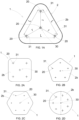
- the distribution of the transducers in a microphone unit can have the shape of an equilateral triangle, wherein the central transducer is arranged in the center of the triangle and the peripheral transducers are arranged at the vertices of the triangle.
- the PCB of the microphone unit is shaped like an equilateral triangle that circumscribes the transducers.
- Such a triangular shape of the microphone unit allows for making larger microphone meta-arrays without geometric limitations, while keeping the overall distribution of transducers as uniform as possible.
- the flexibility of use of such triangular microphone units allows for assembling an unlimited number of geometries for microphone arrays, which can be reconfigured in a few minutes and always reusing the same microphone units.
- a triangular microphone unit according to the invention is disclosed, which is generally indicated with reference numeral 1.
- the microphone unit (1) comprises a PCB (2) and a plurality of transducers (3) mounted on the PCB.
- the PCB (2) is a rigid planar PCB and has a front side (2b) ( Fig. 1A ) suitable for facing a sound source, and a back side (2a) ( Fig. 1 ) wherein the transducers (3) are mounted.
- Through holes (20) are cut in the PCB (2) in correspondence with each transducer (3) in such a way that the acoustic waves emitted from the sound source pass through the PCB (2) and hit the transducers (3).
- Each transducer (3) is an acoustic-electric transducer and has a digital output; that is to say, the transducer (3) is suitable for converting a sound signal into an electrical signal of digital type.
- Each transducer (3) consists of a MEMS (Micro Electro Mechanical Systems) capsule that provides a good cost/performance ratio and a long-term stability.
- the MEMS capsule has a digital output, for example of PDM (Pulse Density Modulation) type.
- the digital outputs of the transducers (3) are connected to an A2B audio interface (4) by means of respective tracks (21) of the PCB (2).
- the audio interface A2B (B) is a transceiver suitable for receiving the digital signal of the transducers (3) and converting said digital signal into a suitable format for being sent in an A2B audio bus having substantial advantages in terms of noise immunity even in long connections and of connection reliability.
- the A2B audio interface (4) is connected to an electrical input connector (5) and an electrical output connector (105) by means of respective tracks (22; 122) of the PCB (2).
- the electrical connectors (5; 105) are suitable for connecting an A2B audio bus that uses a simple twisted pair (UTP cable).
- the plurality of transducers (3) comprises a central transducer (30) and at least three peripheral transducers (31) arranged at the same radial distance (r) from the central transducer (30) and equally angularly spaced. In this way a peripheral transducer is spaced from the two nearest peripheral transducers by the same distance (L).
- Figs. 1 and 1A illustrate a triangular arrangement of four transducers (3), wherein the central transducer (30) is arranged at the center of an equilateral triangle and the peripheral transducers (31) are arranged at the three vertices of the equilateral triangle, so that the three peripheral transducers (31) are equally spaced by an angle of 120°, i.e. one peripheral transducer is spaced from the two nearest peripheral transducers by the same distance (L) that is equal to the side of the equilateral triangle.
- the PCB (2) has a triangular shape in order to circumscribe the triangular arrangement of the transducers as efficiently as possible.
- the transducers (3), the A2B audio interface (4), and the electrical connectors (5; 105) are mounted on the back side (2a) of the PCB. Therefore, the front side (2b) of the PCB, that is the one that will face the sound field, is perfectly flat, smooth and free from any obstacle. This is a very important acoustic feature, especially when large planar microphone meta-arrays with many microphone units arranged side by side are to be realized.
- the microphone unit (1) may have a number of transducers (3) higher than four, disposed in a regular polygon arrangement, wherein the central transducer (30) is arranged at the geometric center of the regular polygon and the peripheral transducers (31) are arranged at the vertices of the regular polygon.
- Fig. 2A illustrates a square arrangement of five transducers (3), wherein the central transducer (30) is arranged at the center of a square and the peripheral transducers (31) are arranged at the four vertices of the square, so that the four peripheral transducers (31) are angularly equidistant by an angle of 90°.
- the PCB (2) has a square shape.
- Fig. 2B illustrates a pentagonal arrangement of six transducers (3), wherein the central transducer (30) is arranged at the center of a pentagon and the peripheral transducers (31) are arranged at the five vertices of the pentagon, so that the five peripheral transducers (31) are angularly equidistant by an angle of 72°.
- the PCB (2) has a pentagonal shape.
- Fig. 2C illustrates a hexagonal arrangement of seven transducers (3), wherein the central transducer (30) is arranged at the center of a hexagon and the peripheral transducers (31) are arranged at the six vertices of the hexagon, so that the six peripheral transducers (31) are angularly equidistant by an angle of 60°.
- the PCB (2) has a hexagonal shape.
- arrangements of transducers and shapes of the PCB can be provided according to regular polygons with more than six sides.
- Fig. 2D illustrates a heptagonal arrangement of eight transducers (3), wherein the central transducer (30) is arranged at the center of a heptagon and the peripheral transducers (31) are angularly equidistant by an angle of 51.4° at the seven vertices of the heptagon, so that the seven peripheral transducers (31) are angularly equidistant by an angle 51.4°.
- the PCB (2) has a circular shape.
- the PCB (2) can always have a circular shape that circumscribes the polygon.
- the central transducer (30) is used as a reference microphone and provides a very robust beam-forming.
- the A2B audio interface (4) allows to obtain an audio signal in a particularly robust and effective digital format, which can be transmitted even at great distances (over 40 m), with a high noise rejection capability and a latency reduced to only 50 ⁇ s.
- each microphone unit (1) can be connected to another microphone unit (1) by means of an A2B bus (6) in such a way to obtain a microphone meta-array (100) comprising a plurality of microphone units (1) connected in cascade.
- a microphone meta-array (100) comprising a plurality of microphone units (1) connected in cascade.
- an open daisy-chain comprising a first microphone unit (1a) and a last microphone unit (1n) is obtained.
- the bus A2B (6) consists of a twisted pair and is suitable for carrying both the digital signal detected by the transducers (3) and the power supply of the microphone units (1).
- a certain number of microphone units can be connected on the same bus A2B (6); in particular, a maximum of seven microphone units (1) with 4 channels each.
- the first microphone unit (1a) is connected to an A2B master (7) on one side and to the next microphone unit (1b) on the other side; each intermediate microphone unit (1b, 1c, 1d... 1n-1) is connected between two microphone units, i.e. the previous and the following microphone units, whereas the last microphone unit (1n) is connected to the previous microphone unit only (1n-1).
- the A2B bus (6) that connects two adjacent microphone units (1) can have a maximum length of 15 meters.
- the A2B bus (6) carries both the digital audio signal and the power supply.
- the A2B bus (6) has terminals made up of conductors inserted in the electrical connectors (5; 105) of the microphone units.
- the electrical connectors (5; 105) of the microphone units are inexpensive and simple to assemble.
- the microphone meta-array (100) can be integrated in an A2B network (200), wherein the first microphone unit (1a) of the microphone meta-array is connected to an A2B master (7) that manages all microphone units (1) of the microphone meta-array; therefore, all microphone units (1) of the microphone meta-array operate as slaves in the network.
- the first microphone unit (1a) is connected to the A2B master (7) by means of an A2B bus (6).
- the A2B master (7) provides a digital clock for all signals in the network, in order to keep the operation of the transducers (3) of the microphone units (1) perfectly synchronous.
- the A2B master (7) can receive up to 28 signals from the microphone units.
- the A2B master (7) is connected to a power supply (P) in order to power all microphone units.
- the A2B master (7) is connected to a host-processor (8) by means of two digital interfaces (70) of TDM-16 type.
- the A2B master (7) can manage a certain number of slave units depending on the network configuration; therefore, in the case of microphone units (1) with four microphones each, the microphone meta-array (100) can comprise a maximum of seven microphone units (1).
- the host-processor (8) has more than two incoming TDM-16 interfaces, multiple A2B masters (7) can be used and consequently one or more microphone meta-arrays (100) with a higher number of microphone units (1) connected.
- the acoustic signals detected by the transducers (3) of each microphone unit (1) are sent in digital synchronous format to the master A2B (7) which sends them to the host-processor (8). Then, the signals received by the host-processor (8) are synchronously acquired and analyzed by the host-processor (8) which is configured to process said signals to obtain a beam-forming of said signals by means of any beam-forming algorithm (e.g. "regularized Kirkeby inversion" or "MVDR - minimum variance distortionless response").
- any beam-forming algorithm e.g. "regularized Kirkeby inversion" or "MVDR - minimum variance distortionless response”
- Fig. 4 illustrates an A2B network (300), wherein three A2B masters (7) are connected to the host-processor (8). Each A2B master (7) is connected to a microphone meta-array (100). In such a case, being part of the same network (200), the three microphone meta-arrays (100) can be physically combined in close arrangements, in such a way to obtain a microphone group (300) comprising several microphone meta-arrays that are part of the same network or a single microphone meta-array that comprises all microphone units (1).
- each microphone meta-array (100) has seven microphone units (1) comprising 4 transducers (3)
- the network (200) of Fig. 4 comprises 84 transducers (3), resulting in a very accurate reconstruction of the sound signal with a minimum volume.
- the microphone meta-array (100) It is not necessary to adopt any predefined geometry in order to realize the microphone meta-array (100). However, some particular geometries of the microphone meta-array (100) may be optimal to improve its acoustic performance.
- the microphone units (1) must be electrically connected by means of the A2B buses (6).
- the PCBs (2) of the microphone units can be arranged in adjacent position and connected by soldering or held together using rigid or flexible connectors.
- the flexible wiring by means of the A2B bus (6) allows to cover the surface of any object, such as a machinery, a vehicle, a human body or a wall, with microphone units (1).
- any object such as a machinery, a vehicle, a human body or a wall, with microphone units (1).
- Fig. 5 illustrates a vehicle (V) wherein a microphone meta-array (100) of compact type is installed, said microphone meta-array (100) comprising a plurality of microphone units (1) connected in cascade by means of an A2B bus (6).
- the microphone meta-array (100) is part of an A2B network (200), wherein the first microphonic unit is connected to the A2B master (7) which in turn is connected to the host-processor (8).
- the beam-forming performed by the host-processor (8) on the signals coming from the transducers (3) of the microphone units (1) of the microphone meta-array (100) enhances the sound coming from a specific direction and rejects the sound coming from other directions. This is especially useful in different applications, such as handsfree communication, ILZ (Individualized Listening Zone) or ANC (Active Noise Cancellation).
- ILZ Intelligentized Listening Zone
- ANC Active Noise Cancellation
- Figs. 6A, 6B, and 6C illustrate three different layouts of dome-shaped microphone meta-arrays (100), respectively comprising 3, 4, and 5 triangular microphone units, and therefore 12, 16, and 20 transducers (3).
- the lateral edges of the PCBs (2) are fixed by means of fixing means (9), such as soldering, gluing, interlocking, connectors and the like, so as to obtain a pyramid with a triangular, square, pentagonal base, respectively.
- the microphone meta-array (100) can be inserted in an A2B network (200) having only one A2B master, such as the one illustrated in Fig. 3 .
- the dome-shaped configurations of the microphone meta-array are particularly interesting for video conferencing applications, i.e., when the microphone array must be positioned in the center of a table and the virtual microphones obtained by means of the beam-forming are directed towards the participants' mouths.
- Fig. 7 illustrates a three-dimensional microphone meta-array (100) with 4 triangular microphone units (1) and 16 transducers (3).
- the lateral edges of the PCBs (2) of the microphone units fixed by means of fixing means (9) so as to obtain a regular tetrahedron.
- the microphone meta-array (100) can be inserted into an A2B network (200) having only one A2B master, such as that illustrated in Fig. 3 .
- the regular tetrahedron geometry is typical of the microphone arrays of the prior art, which only comprise four transducers arranged at the vertices of the tetrahedron.
- the microphone meta-array (100) of Fig. 7 comprises four triangular microphone units, one on each side, each microphone unit being provided with four transducers, and therefore the performance of such a solution is significantly higher than the tetrahedron microphone arrays of the prior art.
- Fig. 8 illustrates a planar microphone meta-array (100) comprising six triangular microphone units (1) and 24 transducers (3).
- the lateral edges of the PCBs (2) of the microphone units are fixed by means of fixing means (9).
- Such a geometry is preferred when the spatial information is enclosed in a semi-space.
- the microphone meta-array (100) can be inserted in an A2B network (200) having only one A2B master, such as the one illustrated in Fig. 3 .
- Fig. 9 illustrates a three-dimensional microphone meta-array (100) comprising eight triangular microphone units (1) for a total of 32 transducers.
- the lateral edges of the PCBs (2) of the microphone units are fixed by means of fixing means (9) so as to obtain a regular octahedron.
- the microphone meta-array (100) of Fig. 9 comprises eight triangular microphone units, one on each side, each microphone unit being provided with four transducers, and therefore the performance of such a solution is significantly higher than the octahedron microphone arrays of the prior art.
- Figs. 10A and 10B illustrate two cylindrical microphonic meta-arrays (300).
- the microphone meta-array (300) of Fig. 10A comprises eight triangular microphone units (1) with a total of 32 transducers.
- the lateral edges of the PCBs (2) of the microphone units are fixed by means of fixing means (9) so as to obtain a substantially cylindrical shape.
- fixing means (9) so as to obtain a substantially cylindrical shape.
- the number of microphone units (1) is higher than seven, it is necessary to use an A2B network (200) with two A2B masters (7), such as the one illustrated in Fig. 4 .
- the microphone meta-array (300) of Fig. 10B comprises 16 microphone units (1) with a total of 64 transducers. In such a case, since the number of microphone units (1) is higher than 14, it is necessary to use an A2B network (200) with three A2B masters (7), such as the one illustrated in Fig. 4 .
- Said cylindrical microphone arrays are particularly useful when the spatial information is located primarily in one plane and the sound coming from above and from below is less relevant.
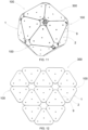
- Fig. 11 illustrates a three-dimensional microphone meta-array (300) comprising 20 triangular microphone units (1) with a total of 80 transducers.
- the lateral edges of the PCBs (2) of the microphone units are fixed by means of fixing means (9) so as to obtain a regular icosahedron.
- Fig. 12 illustrates a planar microphone meta-array (300) comprising 13 triangular microphone units (1) for a total of 52 transducers.
- the lateral edges of the PCBs (2) of the microphone units are fixed by means of fixing means (9).
- Such a microphonic meta-array (300) can be used when the spatial information is enclosed in a semi-space, like the microphonic meta-array (100) of Fig. 8 , but obviously the microphone meta-array (300) of Fig. 12 has a much higher performance than the microphone meta-array (100) of Fig. 8 because the number of transducers (3) is more than doubled.
Landscapes
- Engineering & Computer Science (AREA)
- Health & Medical Sciences (AREA)
- Physics & Mathematics (AREA)
- Otolaryngology (AREA)
- Signal Processing (AREA)
- Acoustics & Sound (AREA)
- General Health & Medical Sciences (AREA)
- Theoretical Computer Science (AREA)
- Multimedia (AREA)
- Audiology, Speech & Language Pathology (AREA)
- Human Computer Interaction (AREA)
- General Engineering & Computer Science (AREA)
- General Physics & Mathematics (AREA)
- Circuit For Audible Band Transducer (AREA)
- Obtaining Desirable Characteristics In Audible-Bandwidth Transducers (AREA)
Claims (11)
- Mikrofoneinheit (1), umfassend:- eine einzelne Leiterplatte (2) mit einer Vorderseite (2b), die dazu geeignet ist, einer Schallquelle zugewandt zu sein, und mit einer Rückseite (2a),- eine Vielzahl von Wandlern (3), die auf der Rückseite (2a) der Leiterplatte eingebaut sind; wobei jeder Wandler (3) vom elektroakustischen Typ ist mit einem Digitalausgang, der dazu geeignet ist, ein Klangsignal in ein elektrisches Signal vom digitalen Typ umzuwandeln,- Durchgangslöcher (20), die auf der Leiterplatte (2) in Übereinstimmung mit jedem Wandler (3) so herausgearbeitet sind, dass die von der Schallquelle abgegebenen akustischen Wellen die Leiterplatte (2) durchqueren und auf die Wandler (3) auftreffen,- eine A2B-Audioschnittstelle (4), die auf der Rückseite (2a) der Leiterplatte eingebaut ist und elektrisch mit den Wandlern (3) verbunden ist; wobei die A2B-Audioschnittstelle (4) ein Sendeempfänger ist, der dazu geeignet ist, das von den Wandlern (3) ausgehende Digitalsignal zu empfangen und in ein A2B-Format umzuwandeln, das dazu geeignet ist, in einen A2B-Audiobus gesendet zu werden, und- einen elektrischen Eingangsverbinder (5) und einen elektrischen Ausgangsverbinder (105), die auf der Rückseite (2a) der Leiterplatte eingebaut sind und elektrisch mit der A2B-Audioschnittstelle (4) verbunden sind; wobei die elektrischen Eingangs- und Ausgangsverbinder (5; 105) dazu geeignet sind, jeweilige A2B-Audiobusse (6) zu verbinden, die ein einzelnes Twisted-Pair verwenden, so dass die Mikrofoneinheit (1) an eine oder zwei benachbarte Mikrofoneinheiten (1) in Daisy-Chain-Konfiguration angeschlossen werden kann und eine Meta-Anordnung (100) bildet, die dazu bestimmt ist, an ein A2B-Netz (300) mit einem Host-Prozessor (8) angeschlossen zu werden, der konfiguriert ist, eine Strahlformung von Signalen vorzunehmen, die von allen Wandlern (3) der Mikrofoneinheiten (1) der Meta-Anordnung (100) ausgehen;wobei die Vielzahl von Wandlern (3) einen zentralen Wandler (30) und mindestens drei periphere Wandler (31) umfasst, die in demselben radialen Abstand (r) von dem zentralen Wandler (30) angeordnet und gleichwinklig voneinander beabstandet sind.
- Mikrofoneinheit (1) nach Anspruch 1, wobei die Wandler (3) mittels Bahnen (21) der Leiterplatte (2) elektrisch mit der A2B-Audioschnittstelle (4) verbunden sind und die elektrischen Eingangs- und Ausgangsverbinder (5; 105) mittels einer Bahn (22; 122) der Leiterplatte (2) elektrisch mit der A2B-Audioschnittstelle (4) verbunden sind.
- Mikrofoneinheit (1) nach Anspruch 1 oder 2, wobei jeder Wandler (3) aus einer MEMS(Micro Electro Mechanical Systems)-Kapsel besteht.
- Mikrofoneinheit (1) nach einem der vorstehenden Ansprüche, umfassend vier Wandler (3), die in einer Anordnung eines gleichseitigen Dreiecks angeordnet sind, wobei der zentrale Wandler (30) im Mittelpunkt des gleichseitigen Dreiecks angeordnet ist und die peripheren Wandler (31) in Übereinstimmung mit den drei Spitzen des gleichseitigen Dreiecks angeordnet sind.
- Mikrofoneinheit (1) nach Anspruch 4, wobei die Leiterplatte (2) eine dreieckige Form aufweist, die die Anordnung in Form eines gleichseitigen Dreiecks der Wandler (3) einschreibt.
- Mikrofoneinheit (1) nach einem der Ansprüche 1 bis 3, umfassend mehr als vier Wandler (3), die in Form einer regelmäßigen Vieleckanordnung angeordnet sind, wobei der zentrale Wandler (30) im Mittelpunkt des regelmäßigen Vielecks angeordnet ist und die peripheren Wandler (31) in Übereinstimmung mit den Spitzen des regelmäßigen Vielecks angeordnet sind.
- Mikrofoneinheit (1) nach Anspruch 6, wobei die Leiterplatte (2) die Form eines regelmäßigen Vielecks oder eines Kreises aufweist, der die regelmäßige Vieleckanordnung der Wandler (3) einschreibt.
- Mikrofon-Meta-Anordnung (100), umfassend eine Vielzahl von Mikrofoneinheiten (1) nach einem der vorstehenden Ansprüche, die elektrisch in Kaskade in einer Daisy-Chain-Konfiguration mittels eines A2B-Audiobusses (6) verbunden sind, der ein Twisted-Pair verwendet; wobei die Meta-Anordnung (100) dazu bestimmt ist, an ein A2B-Netz (300) mit einem Host-Prozessor (8) verbunden zu werden, der konfiguriert ist, eine Strahlformung von Signalen vorzunehmen, die von allen Wandlern (3) der Mikrofoneinheiten (1) der Meta-Anordnung (100) eingehen.
- Mikrofon-Meta-Anordnung (100) nach Anspruch 8, wobei die Leiterplatten (2) der Mikrofoneinheiten seitliche Kanten aufweisen, die mittels Befestigungsmitteln (9) so aneinander befestigt sind, dass eine kompakte Meta-Anordnung (200) erhalten wird, die eine flache zweidimensionale oder dreidimensionale Form aufweist.
- A2B-Netz (300), umfassend:- mindestens eine Mikrofon-Meta-Anordnung (100) nach Anspruch 8 oder 9,- mindestens einen Master-A2B (7), der mittels eines A2B-Busses (6) mit einer ersten Mikrofoneinheit (1a) der Mikrofon-Meta-Anordnung (100) verbunden ist und konfiguriert ist, um alle Mikrofoneinheiten (1) der Mikrofon-Meta-Anordnung zu steuern und Signale, die von den Wandlern (3) aller Mikrofoneinheiten eingehen, zu synchronisieren,- ein Netzteil (P), das mit dem Master-A2B (7) verbunden ist, um die Mikrofoneinheiten der Mikrofon-Meta-Anordnung zu versorgen,- einen Host-Prozessor (8), der mit dem Master-A2B (7) verbunden ist und konfiguriert ist, um eine Strahlformung von Signalen vorzunehmen, die von allen Wandlern (3) der Mikrofoneinheiten (1) der Meta-Anordnung (100) eingehen.
- Fahrzeug (V), umfassend ein A2B-Netz (300) nach Anspruch 10, wobei die Mikrofon-Meta-Anordnung (100) an Bord des Fahrzeugs (V) angeordnet ist.
Applications Claiming Priority (2)
| Application Number | Priority Date | Filing Date | Title |
|---|---|---|---|
| IT202000024052 | 2020-10-13 | ||
| PCT/EP2021/077233 WO2022078791A1 (en) | 2020-10-13 | 2021-10-04 | Microphone unit, microphone meta-array and network with microphone meta-array |
Publications (2)
| Publication Number | Publication Date |
|---|---|
| EP4229875A1 EP4229875A1 (de) | 2023-08-23 |
| EP4229875B1 true EP4229875B1 (de) | 2024-11-06 |
Family
ID=74068440
Family Applications (1)
| Application Number | Title | Priority Date | Filing Date |
|---|---|---|---|
| EP21786878.5A Active EP4229875B1 (de) | 2020-10-13 | 2021-10-04 | Mikrofoneinheit, mikrofon-meta-array und netzwerk mit mikrofon-meta-array |
Country Status (5)
| Country | Link |
|---|---|
| US (1) | US12256201B2 (de) |
| EP (1) | EP4229875B1 (de) |
| JP (1) | JP2023545961A (de) |
| CN (1) | CN116325794A (de) |
| WO (1) | WO2022078791A1 (de) |
Families Citing this family (4)
| Publication number | Priority date | Publication date | Assignee | Title |
|---|---|---|---|---|
| US12574679B2 (en) * | 2020-11-12 | 2026-03-10 | Analog Devices International Unlimited Company | Systems and techniques for microphone array calibration |
| CN116320858A (zh) * | 2023-03-29 | 2023-06-23 | 浙江华创视讯科技有限公司 | 传输音频的方法及装置 |
| US20240381022A1 (en) * | 2023-05-12 | 2024-11-14 | Shure Acquisition Holdings, Inc. | Multi-dimensional array microphone |
| CN116709282B (zh) * | 2023-06-20 | 2024-05-24 | 河北初光汽车部件有限公司 | 一种可方便拆装的汽车蓝牙音频系统 |
Family Cites Families (14)
| Publication number | Priority date | Publication date | Assignee | Title |
|---|---|---|---|---|
| GB1512514A (en) * | 1974-07-12 | 1978-06-01 | Nat Res Dev | Microphone assemblies |
| JPH0763199B2 (ja) | 1984-09-18 | 1995-07-05 | 日本電信電話株式会社 | 電気音響変換装置 |
| US9143879B2 (en) * | 2011-10-19 | 2015-09-22 | James Keith McElveen | Directional audio array apparatus and system |
| DE102013001385A1 (de) * | 2013-01-26 | 2014-07-31 | Audi Ag | Kraftfahrzeug und Mikrofon für eine Mikrofonanordnung in dem Kraftfahrzeug |
| KR101403372B1 (ko) | 2013-04-11 | 2014-06-03 | 충남대학교산학협력단 | 정다면체 마이크로폰 어레이 장치 및 상기 정다면체 마이크로폰 어레이 장치를 이용한 3차원 공간에서의 소음원 측정 방법 |
| DE102013019194B4 (de) * | 2013-11-15 | 2016-03-24 | Audi Ag | Kraftfahrzeug-Mikrofonsystem mit adaptiver Richtcharakteristik |
| US9851938B2 (en) * | 2016-04-26 | 2017-12-26 | Analog Devices, Inc. | Microphone arrays and communication systems for directional reception |
| EP3574659B1 (de) * | 2017-01-27 | 2025-06-18 | Shure Acquisition Holdings, Inc. | Mikrofonanordnungsmodul und system |
| EP3571852A1 (de) | 2017-02-24 | 2019-11-27 | Huawei Technologies Co., Ltd. | Mikrofonanordnung mit rekonfigurierbarer geometrie |
| GB2545359B (en) | 2017-03-03 | 2018-02-14 | Asdsp Ltd | Device for capturing and outputting audio |
| CN109545230B (zh) * | 2018-12-05 | 2021-10-19 | 百度在线网络技术(北京)有限公司 | 车辆内的音频信号处理方法和装置 |
| CN210958793U (zh) | 2019-11-15 | 2020-07-07 | 江苏开沃汽车有限公司 | 一种车载阵列式麦克风 |
| US11411607B2 (en) * | 2020-01-07 | 2022-08-09 | Analog Devices, Inc. | Audio and lighting control via a communication bus |
| CN210518820U (zh) | 2020-04-08 | 2020-05-12 | 歌尔股份有限公司 | 音频电子装置及其设置有音频电子装置的设备 |
-
2021
- 2021-10-04 EP EP21786878.5A patent/EP4229875B1/de active Active
- 2021-10-04 CN CN202180067815.XA patent/CN116325794A/zh active Pending
- 2021-10-04 WO PCT/EP2021/077233 patent/WO2022078791A1/en not_active Ceased
- 2021-10-04 US US18/044,292 patent/US12256201B2/en active Active
- 2021-10-04 JP JP2023519808A patent/JP2023545961A/ja active Pending
Also Published As
| Publication number | Publication date |
|---|---|
| US20230328430A1 (en) | 2023-10-12 |
| EP4229875A1 (de) | 2023-08-23 |
| US12256201B2 (en) | 2025-03-18 |
| CN116325794A (zh) | 2023-06-23 |
| JP2023545961A (ja) | 2023-11-01 |
| WO2022078791A1 (en) | 2022-04-21 |
Similar Documents
| Publication | Publication Date | Title |
|---|---|---|
| EP4229875B1 (de) | Mikrofoneinheit, mikrofon-meta-array und netzwerk mit mikrofon-meta-array | |
| US12063473B2 (en) | Array microphone module and system | |
| US11109133B2 (en) | Array microphone module and system | |
| US9143879B2 (en) | Directional audio array apparatus and system | |
| US20220360890A1 (en) | Steerable speaker array, system and method for the same | |
| CN112335261B (zh) | 图案形成麦克风阵列 | |
| EP3466109B1 (de) | Mikrofonanordnungen für verbesserte horizontale richtwirkung | |
| US9307326B2 (en) | Surface-mounted microphone arrays on flexible printed circuit boards | |
| US9402117B2 (en) | Wearable directional microphone array apparatus and system | |
| AU2004234906B2 (en) | Headphone for spatial sound reproduction | |
| US10827259B2 (en) | Microphone assembly having a reconfigurable geometry | |
| CN113301476B (zh) | 拾音设备及麦克风阵列结构 | |
| CN210958798U (zh) | 环绕型麦克风单元及应用其的拾音装置和助听设备 | |
| JP2010028162A (ja) | 放収音装置 | |
| JPWO2022228966A5 (de) |
Legal Events
| Date | Code | Title | Description |
|---|---|---|---|
| STAA | Information on the status of an ep patent application or granted ep patent |
Free format text: STATUS: UNKNOWN |
|
| STAA | Information on the status of an ep patent application or granted ep patent |
Free format text: STATUS: THE INTERNATIONAL PUBLICATION HAS BEEN MADE |
|
| PUAI | Public reference made under article 153(3) epc to a published international application that has entered the european phase |
Free format text: ORIGINAL CODE: 0009012 |
|
| STAA | Information on the status of an ep patent application or granted ep patent |
Free format text: STATUS: REQUEST FOR EXAMINATION WAS MADE |
|
| 17P | Request for examination filed |
Effective date: 20230307 |
|
| AK | Designated contracting states |
Kind code of ref document: A1 Designated state(s): AL AT BE BG CH CY CZ DE DK EE ES FI FR GB GR HR HU IE IS IT LI LT LU LV MC MK MT NL NO PL PT RO RS SE SI SK SM TR |
|
| DAV | Request for validation of the european patent (deleted) | ||
| DAX | Request for extension of the european patent (deleted) | ||
| GRAP | Despatch of communication of intention to grant a patent |
Free format text: ORIGINAL CODE: EPIDOSNIGR1 |
|
| STAA | Information on the status of an ep patent application or granted ep patent |
Free format text: STATUS: GRANT OF PATENT IS INTENDED |
|
| INTG | Intention to grant announced |
Effective date: 20240524 |
|
| GRAS | Grant fee paid |
Free format text: ORIGINAL CODE: EPIDOSNIGR3 |
|
| GRAA | (expected) grant |
Free format text: ORIGINAL CODE: 0009210 |
|
| STAA | Information on the status of an ep patent application or granted ep patent |
Free format text: STATUS: THE PATENT HAS BEEN GRANTED |
|
| AK | Designated contracting states |
Kind code of ref document: B1 Designated state(s): AL AT BE BG CH CY CZ DE DK EE ES FI FR GB GR HR HU IE IS IT LI LT LU LV MC MK MT NL NO PL PT RO RS SE SI SK SM TR |
|
| REG | Reference to a national code |
Ref country code: GB Ref legal event code: FG4D |
|
| REG | Reference to a national code |
Ref country code: CH Ref legal event code: EP |
|
| REG | Reference to a national code |
Ref country code: DE Ref legal event code: R096 Ref document number: 602021021518 Country of ref document: DE |
|
| REG | Reference to a national code |
Ref country code: IE Ref legal event code: FG4D |
|
| P01 | Opt-out of the competence of the unified patent court (upc) registered |
Free format text: CASE NUMBER: APP_1226/2025 Effective date: 20250109 |
|
| REG | Reference to a national code |
Ref country code: LT Ref legal event code: MG9D |
|
| REG | Reference to a national code |
Ref country code: NL Ref legal event code: MP Effective date: 20241106 |
|
| PG25 | Lapsed in a contracting state [announced via postgrant information from national office to epo] |
Ref country code: PT Free format text: LAPSE BECAUSE OF FAILURE TO SUBMIT A TRANSLATION OF THE DESCRIPTION OR TO PAY THE FEE WITHIN THE PRESCRIBED TIME-LIMIT Effective date: 20250306 Ref country code: HR Free format text: LAPSE BECAUSE OF FAILURE TO SUBMIT A TRANSLATION OF THE DESCRIPTION OR TO PAY THE FEE WITHIN THE PRESCRIBED TIME-LIMIT Effective date: 20241106 Ref country code: IS Free format text: LAPSE BECAUSE OF FAILURE TO SUBMIT A TRANSLATION OF THE DESCRIPTION OR TO PAY THE FEE WITHIN THE PRESCRIBED TIME-LIMIT Effective date: 20250306 |
|
| PG25 | Lapsed in a contracting state [announced via postgrant information from national office to epo] |
Ref country code: FI Free format text: LAPSE BECAUSE OF FAILURE TO SUBMIT A TRANSLATION OF THE DESCRIPTION OR TO PAY THE FEE WITHIN THE PRESCRIBED TIME-LIMIT Effective date: 20241106 Ref country code: NL Free format text: LAPSE BECAUSE OF FAILURE TO SUBMIT A TRANSLATION OF THE DESCRIPTION OR TO PAY THE FEE WITHIN THE PRESCRIBED TIME-LIMIT Effective date: 20241106 |
|
| REG | Reference to a national code |
Ref country code: AT Ref legal event code: MK05 Ref document number: 1740706 Country of ref document: AT Kind code of ref document: T Effective date: 20241106 |
|
| PG25 | Lapsed in a contracting state [announced via postgrant information from national office to epo] |
Ref country code: BG Free format text: LAPSE BECAUSE OF FAILURE TO SUBMIT A TRANSLATION OF THE DESCRIPTION OR TO PAY THE FEE WITHIN THE PRESCRIBED TIME-LIMIT Effective date: 20241106 |
|
| PG25 | Lapsed in a contracting state [announced via postgrant information from national office to epo] |
Ref country code: ES Free format text: LAPSE BECAUSE OF FAILURE TO SUBMIT A TRANSLATION OF THE DESCRIPTION OR TO PAY THE FEE WITHIN THE PRESCRIBED TIME-LIMIT Effective date: 20241106 |
|
| PG25 | Lapsed in a contracting state [announced via postgrant information from national office to epo] |
Ref country code: NO Free format text: LAPSE BECAUSE OF FAILURE TO SUBMIT A TRANSLATION OF THE DESCRIPTION OR TO PAY THE FEE WITHIN THE PRESCRIBED TIME-LIMIT Effective date: 20250206 |
|
| PG25 | Lapsed in a contracting state [announced via postgrant information from national office to epo] |
Ref country code: LV Free format text: LAPSE BECAUSE OF FAILURE TO SUBMIT A TRANSLATION OF THE DESCRIPTION OR TO PAY THE FEE WITHIN THE PRESCRIBED TIME-LIMIT Effective date: 20241106 Ref country code: GR Free format text: LAPSE BECAUSE OF FAILURE TO SUBMIT A TRANSLATION OF THE DESCRIPTION OR TO PAY THE FEE WITHIN THE PRESCRIBED TIME-LIMIT Effective date: 20250207 Ref country code: AT Free format text: LAPSE BECAUSE OF FAILURE TO SUBMIT A TRANSLATION OF THE DESCRIPTION OR TO PAY THE FEE WITHIN THE PRESCRIBED TIME-LIMIT Effective date: 20241106 |
|
| PG25 | Lapsed in a contracting state [announced via postgrant information from national office to epo] |
Ref country code: PL Free format text: LAPSE BECAUSE OF FAILURE TO SUBMIT A TRANSLATION OF THE DESCRIPTION OR TO PAY THE FEE WITHIN THE PRESCRIBED TIME-LIMIT Effective date: 20241106 |
|
| PG25 | Lapsed in a contracting state [announced via postgrant information from national office to epo] |
Ref country code: RS Free format text: LAPSE BECAUSE OF FAILURE TO SUBMIT A TRANSLATION OF THE DESCRIPTION OR TO PAY THE FEE WITHIN THE PRESCRIBED TIME-LIMIT Effective date: 20250206 |
|
| PG25 | Lapsed in a contracting state [announced via postgrant information from national office to epo] |
Ref country code: SM Free format text: LAPSE BECAUSE OF FAILURE TO SUBMIT A TRANSLATION OF THE DESCRIPTION OR TO PAY THE FEE WITHIN THE PRESCRIBED TIME-LIMIT Effective date: 20241106 |
|
| PG25 | Lapsed in a contracting state [announced via postgrant information from national office to epo] |
Ref country code: DK Free format text: LAPSE BECAUSE OF FAILURE TO SUBMIT A TRANSLATION OF THE DESCRIPTION OR TO PAY THE FEE WITHIN THE PRESCRIBED TIME-LIMIT Effective date: 20241106 |
|
| PG25 | Lapsed in a contracting state [announced via postgrant information from national office to epo] |
Ref country code: EE Free format text: LAPSE BECAUSE OF FAILURE TO SUBMIT A TRANSLATION OF THE DESCRIPTION OR TO PAY THE FEE WITHIN THE PRESCRIBED TIME-LIMIT Effective date: 20241106 |
|
| PG25 | Lapsed in a contracting state [announced via postgrant information from national office to epo] |
Ref country code: RO Free format text: LAPSE BECAUSE OF FAILURE TO SUBMIT A TRANSLATION OF THE DESCRIPTION OR TO PAY THE FEE WITHIN THE PRESCRIBED TIME-LIMIT Effective date: 20241106 |
|
| PG25 | Lapsed in a contracting state [announced via postgrant information from national office to epo] |
Ref country code: SK Free format text: LAPSE BECAUSE OF FAILURE TO SUBMIT A TRANSLATION OF THE DESCRIPTION OR TO PAY THE FEE WITHIN THE PRESCRIBED TIME-LIMIT Effective date: 20241106 |
|
| PG25 | Lapsed in a contracting state [announced via postgrant information from national office to epo] |
Ref country code: CZ Free format text: LAPSE BECAUSE OF FAILURE TO SUBMIT A TRANSLATION OF THE DESCRIPTION OR TO PAY THE FEE WITHIN THE PRESCRIBED TIME-LIMIT Effective date: 20241106 |
|
| REG | Reference to a national code |
Ref country code: DE Ref legal event code: R097 Ref document number: 602021021518 Country of ref document: DE |
|
| PG25 | Lapsed in a contracting state [announced via postgrant information from national office to epo] |
Ref country code: SE Free format text: LAPSE BECAUSE OF FAILURE TO SUBMIT A TRANSLATION OF THE DESCRIPTION OR TO PAY THE FEE WITHIN THE PRESCRIBED TIME-LIMIT Effective date: 20241106 |
|
| PLBE | No opposition filed within time limit |
Free format text: ORIGINAL CODE: 0009261 |
|
| STAA | Information on the status of an ep patent application or granted ep patent |
Free format text: STATUS: NO OPPOSITION FILED WITHIN TIME LIMIT |
|
| 26N | No opposition filed |
Effective date: 20250807 |
|
| PGFP | Annual fee paid to national office [announced via postgrant information from national office to epo] |
Ref country code: IT Payment date: 20250922 Year of fee payment: 5 |
|
| REG | Reference to a national code |
Ref country code: CH Ref legal event code: U11 Free format text: ST27 STATUS EVENT CODE: U-0-0-U10-U11 (AS PROVIDED BY THE NATIONAL OFFICE) Effective date: 20251101 |
|
| PGFP | Annual fee paid to national office [announced via postgrant information from national office to epo] |
Ref country code: LU Payment date: 20251024 Year of fee payment: 5 |
|
| PGFP | Annual fee paid to national office [announced via postgrant information from national office to epo] |
Ref country code: DE Payment date: 20251028 Year of fee payment: 5 |
|
| PGFP | Annual fee paid to national office [announced via postgrant information from national office to epo] |
Ref country code: GB Payment date: 20251023 Year of fee payment: 5 |
|
| PGFP | Annual fee paid to national office [announced via postgrant information from national office to epo] |
Ref country code: MC Payment date: 20251022 Year of fee payment: 5 |
|
| PGFP | Annual fee paid to national office [announced via postgrant information from national office to epo] |
Ref country code: FR Payment date: 20251027 Year of fee payment: 5 |
|
| PGFP | Annual fee paid to national office [announced via postgrant information from national office to epo] |
Ref country code: BE Payment date: 20251024 Year of fee payment: 5 |
|
| PGFP | Annual fee paid to national office [announced via postgrant information from national office to epo] |
Ref country code: CH Payment date: 20251101 Year of fee payment: 5 |
|
| PGFP | Annual fee paid to national office [announced via postgrant information from national office to epo] |
Ref country code: IE Payment date: 20251020 Year of fee payment: 5 |
|
| PGFP | Annual fee paid to national office [announced via postgrant information from national office to epo] |
Ref country code: MT Payment date: 20251028 Year of fee payment: 5 |