EP4229290B1 - Schubumkehrsystem für ein flugzeug und flugzeug mit einem solchen system - Google Patents
Schubumkehrsystem für ein flugzeug und flugzeug mit einem solchen system Download PDFInfo
- Publication number
- EP4229290B1 EP4229290B1 EP21810071.7A EP21810071A EP4229290B1 EP 4229290 B1 EP4229290 B1 EP 4229290B1 EP 21810071 A EP21810071 A EP 21810071A EP 4229290 B1 EP4229290 B1 EP 4229290B1
- Authority
- EP
- European Patent Office
- Prior art keywords
- thrust
- cover
- designed
- reversal
- command
- Prior art date
- Legal status (The legal status is an assumption and is not a legal conclusion. Google has not performed a legal analysis and makes no representation as to the accuracy of the status listed.)
- Active
Links
Images


Classifications
-
- F—MECHANICAL ENGINEERING; LIGHTING; HEATING; WEAPONS; BLASTING
- F02—COMBUSTION ENGINES; HOT-GAS OR COMBUSTION-PRODUCT ENGINE PLANTS
- F02K—JET-PROPULSION PLANTS
- F02K1/00—Plants characterised by the form or arrangement of the jet pipe or nozzle; Jet pipes or nozzles peculiar thereto
- F02K1/54—Nozzles having means for reversing jet thrust
- F02K1/76—Control or regulation of thrust reversers
- F02K1/763—Control or regulation of thrust reversers with actuating systems or actuating devices; Arrangement of actuators for thrust reversers
-
- F—MECHANICAL ENGINEERING; LIGHTING; HEATING; WEAPONS; BLASTING
- F02—COMBUSTION ENGINES; HOT-GAS OR COMBUSTION-PRODUCT ENGINE PLANTS
- F02K—JET-PROPULSION PLANTS
- F02K1/00—Plants characterised by the form or arrangement of the jet pipe or nozzle; Jet pipes or nozzles peculiar thereto
- F02K1/54—Nozzles having means for reversing jet thrust
- F02K1/76—Control or regulation of thrust reversers
- F02K1/766—Control or regulation of thrust reversers with blocking systems or locking devices; Arrangement of locking devices for thrust reversers
-
- F—MECHANICAL ENGINEERING; LIGHTING; HEATING; WEAPONS; BLASTING
- F05—INDEXING SCHEMES RELATING TO ENGINES OR PUMPS IN VARIOUS SUBCLASSES OF CLASSES F01-F04
- F05D—INDEXING SCHEME FOR ASPECTS RELATING TO NON-POSITIVE-DISPLACEMENT MACHINES OR ENGINES, GAS-TURBINES OR JET-PROPULSION PLANTS
- F05D2270/00—Control
- F05D2270/50—Control logic embodiments
- F05D2270/52—Control logic embodiments by electrical means, e.g. relays or switches
-
- F—MECHANICAL ENGINEERING; LIGHTING; HEATING; WEAPONS; BLASTING
- F05—INDEXING SCHEMES RELATING TO ENGINES OR PUMPS IN VARIOUS SUBCLASSES OF CLASSES F01-F04
- F05D—INDEXING SCHEME FOR ASPECTS RELATING TO NON-POSITIVE-DISPLACEMENT MACHINES OR ENGINES, GAS-TURBINES OR JET-PROPULSION PLANTS
- F05D2270/00—Control
- F05D2270/60—Control system actuates means
- F05D2270/62—Electrical actuators
Definitions
- the present invention relates to a thrust reverser system for an aircraft and an aircraft comprising such a system.
- the global control module is usually referred to by the acronym EEC (from the English “Engine Electronic Control”), while the local control module is usually referred to by the acronym ETRAS (from the English “Electrical Thrust Reverser Actuation System”). Furthermore, in these aircraft, the connection between the global control module EEC and the local control module ETRAS is a digital bus, in particular according to the ARINC 429 standard.
- the exchanged data is coded in the form of 32-bit words divided into several distinct fields.
- the digital bus has a pair of twisted strands and the bits are sequentially transmitted in the form of an analog voltage signal between the two strands taking, for each bit, a high value when the bit is worth 1 and a low value when the bit is worth 0.
- the implementation of this standard involves providing complex components both in the global EEC control module to encode the commands in the form of 32-bit words and in the local ETRAS control module to decode the received 32-bit words and deduce the commands from them.
- the local control module is simplified in comparison in particular with that required with an ARINC 42 connection.
- connection comprises two electrical connectors carrying respectively two analog voltage signals, each associated with two ranges of values, each command being associated with a respective one of predefined combinations of the ranges of values for the two electrical connectors.
- connection includes an electrical connector carrying an analog current signal associated with several value ranges, each command being associated with a respective one of the value ranges.
- the local control module includes an analog-to-digital converter designed to convert the analog signal(s) into digital data and a digital module designed to process these digital data to determine commands and control the electric actuator.
- the local control module includes an analog circuit designed to process the analog signal(s) to determine commands and control the electric actuator.
- the electric actuator includes an electric hood moving motor and an inverter configured to electrically activate the electric motor from a DC voltage bus and the local control module is configured to control the inverter.
- the thrust reverser system further comprises a so-called tertiary locking device designed to selectively lock and unlock the cowl
- the cowl is further designed to be selectively moved into a disengaged position facilitating unlocking of the cowl by the tertiary locking device
- the controls include a release command
- the local control module is designed, upon receipt of the release command, to command the primary locking device to unlock the electric motor of the electric actuator of the thrust reverser cowl before commanding the inverter so that the cowl is moved into its release position.
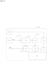
- the aircraft 100 firstly comprises a turbomachine 102.
- the aircraft 100 further comprises a global control module 104, such as an EEC.
- a global control module 104 such as an EEC.
- the aircraft 100 further comprises various components, grouped under the reference 106, different from the aircraft engine, for example aircraft computers, aircraft power supplies, etc.
- the aircraft 100 further comprises a direct voltage bus 108.
- the thrust reverser system 101 firstly comprises a thrust reverser cowl 112 designed to be selectively moved between a stowed position to leave the thrust of the turbomachine 102 unchanged and a deployed position to reverse the thrust of the turbomachine 102.
- the system 101 further comprises an electric actuator 114 of the hood 112.
- the electric actuator 114 comprises an electric motor 116 for moving the hood 112 and an inverter 118 designed to electrically activate the electric motor 116 from the direct voltage bus 108.
- the system 101 further comprises a local control module 120, such as an ETRAS.
- a local control module 120 such as an ETRAS.
- the system 101 further comprises a connection 122 between the global control module 104 and the local control module 120.
- This connection 122 is designed to carry at least one analog signal from the global control module 104 and the local control module 120. This or these analog signals represent commands for the local control module 120.
- connection 122 comprises three electrical conductors 124, 126 and 128.
- the first two electrical conductors 124, 126 are intended to respectively carry two analog voltage signals V1, V2, referenced relative to the third electrical conductor 128 forming an electrical ground.
- the local control module 120 comprises an analog-to-digital converter 124 designed to convert the analog signal(s) (the voltages V1, V2 in the example described) into digital data and a digital module 126 designed to process this digital data to determine the commands received.
- analog-to-digital converter 124 designed to convert the analog signal(s) (the voltages V1, V2 in the example described) into digital data
- digital module 126 designed to process this digital data to determine the commands received.
- the controls include in particular: a stow control for moving the hood 112 into its stowed position and a deploy control for moving the hood 112 into its deployed position.
- the system 101 comprises several locking devices to prevent untimely deployment of the cover 112, for example outside the landing phase of the aircraft 100.
- the system 101 further comprises a so-called primary locking device 132 (from the English “Primary Lock System”) designed to selectively lock (for example by mechanical blocking) and unlock the electric motor 116 of the electric actuator 114 of the thrust reverser cowl 112.
- the local control module 120 is designed to, upon receipt of the deployment command (DEPLOY), control the primary locking device 132 in order to unlock the electric motor 116 of the electric actuator 114 of the thrust reverser cowl 112, before the cowl 112 has been moved into its deployed position.
- STOW stow command
- two thrust reverser systems such as system 101 are provided, with the cowls respectively linked to each other.
- the primary locking device of one of the systems forms a so-called secondary locking device for the other system.
- the system 101 further comprises a so-called tertiary locking device 134 (from the English "Tertiary Lock System") designed to selectively lock and unlock the cowl 112.
- the cowl 112 is preferably further designed to be selectively moved into a released position facilitating unlocking of the cowl by the tertiary locking device 134. This released position is generally an even more folded position.
- the controls then further comprise a release command (from the English "OVERSTOW") and the local control module 120 is then designed to, on receipt of the release command (OVERSTOW), to control the primary locking device 132 in order to unlock the electric motor 116 of the electric actuator 114 of the thrust reverser cowl 112, before controlling the inverter 118 so that the cowl 112 is moved into its release position.
- a release command from the English "OVERSTOW”
- the local control module 120 is then designed to, on receipt of the release command (OVERSTOW), to control the primary locking device 132 in order to unlock the electric motor 116 of the electric actuator 114 of the thrust reverser cowl 112, before controlling the inverter 118 so that the cowl 112 is moved into its release position.
- the tertiary locking device 134 is for example controlled by the members 106, for example by a lever provided in a cockpit of the aircraft 100 which activates the closing of a relay. However, many other means of controlling the tertiary locking device 134 can be provided.
- the local control module 120 is designed to receive commands from the global control module 104, via the connection 122, in order to control the electric actuator 114, and more precisely the inverter 118 in the example described, so as to move the cover 112.
- the local control module 120 is configured to identify one of a plurality of predefined value ranges within which each analog signal falls at a given time, each command being associated with one or more of the value ranges. The local control module 120 is further configured to determine the received command as being associated with the identified value range(s).
- the analog voltage signals V1, V2 are each associated with two ranges of values. For example, one of these two ranges of values extends around the zero voltage and the other range of values extends around 28 V.
- Each command is associated with a respective one of predefined combinations of the ranges of values of the two analog voltage signals V1, V2.
- the commands are coded on three bits [ b1 b2 b3 ] respectively transmitted by the three electrical conductors 126, 130, 128.
- the first bit b1 is transmitted by the first electrical conductor 126 and its values correspond to the two ranges of values for this first electrical conductor 126.
- the second bit b2 is transmitted by the third electrical conductor 130 which is not intended to transmit an analog signal so that the second bit b2 remains at the same value, for example zero.
- the third bit b3 is transmitted by the second electrical conductor 128 and its values correspond to the two ranges of values for this second electrical conductor 128.
- the commands are encoded by the bits [ b1 b2 b3 ] in the following way: [Table 1] [ b1 b2 b3 ] Order [ 0 0 0 ] No order [ 1 0 1 ] OVERSTOW [ 1 0 1 ] DEPLOY [ 1 0 0 ] STOW
- the OVERSTOW and DEPLOY commands have the same code.
- the OVERSTOW command can be carried out, then after a certain delay time (implemented for example by a delay device) the DEPLOY command can be automatically carried out, without requiring the receipt of a new code.
- two different codes could be respectively associated with the OVERSTOW and DEPLOY commands, the latter each being carried out upon receipt of their associated code.
- the system 201 is similar to that of the figure 1 , except that the local control module 120 comprises, in place of 124 and 126, an analog circuit 202 to deduce the commands and control the inverter 118 accordingly.
- connection 122 comprises an electrical connector 304 carrying an analog current signal associated with several value ranges, each command being associated with a respective one of the value ranges.
- the value ranges do not overlap in order to avoid command chatter. More preferably, the value ranges are disjoint, except possibly between the respective ranges of the OVERTOW and DEPLOY commands.
- commands are coded as follows: [Table 2] Current value range Order [ value 1 - value 2 ] OVERSTOW [ value 2 - value 3 ] DEPLOY [ value 4 - value 5 ] STOW
Landscapes
- Engineering & Computer Science (AREA)
- Chemical & Material Sciences (AREA)
- Combustion & Propulsion (AREA)
- Mechanical Engineering (AREA)
- General Engineering & Computer Science (AREA)
- Feedback Control In General (AREA)
- Control Of Electric Motors In General (AREA)
- Transmission Devices (AREA)
- Control Of Multiple Motors (AREA)
Claims (9)
- Schubumkehrsystem (101; 201; 301) für ein Flugzeug (100), umfassend:- eine Haube (112) zur Schubumkehr, die dazu ausgestaltet ist, selektiv verschoben zu werden zwischen einer zusammengeklappten Position, um den Schub eines Turbotriebwerks (102) des Flugzeugs (100) unverändert zu lassen, und einer ausgefahrenen Position, um den Schub des Turbotriebwerks (102) umzukehren;- ein elektrisches Stellglied (114) der Haube (112);- ein lokales Steuerungsmodul (120), das dazu ausgestaltet ist, Befehle ausgehend von einem globalen Steuerungsmodul (104) zu empfangen, um das elektrische Stellglied (114) derart zu steuern, dass die Haube (112) verschoben wird, wobei diese Befehle einschließen:- einen Befehl zum Zusammenklappen, um die Haube (112) in ihre zusammengeklappte Position zu verschieben, und- einen Befehl zum Ausfahren, um die Haube (112) in ihre ausgefahrene Position zu verschieben; und- eine Verbindung (122) zwischen dem globalen Steuerungsmodul (104) und dem lokalen Steuerungsmodul (120), um mindestens ein analoges Signal zu übertragen;dadurch gekennzeichnet, dass das lokale Steuerungsmodul (120) ausgestaltet ist zum:- Identifizieren eines unter mehreren vorab definierten Wertebereichen, in dem sich jedes analoge Signal zu einem gegebenen Zeitpunkt befindet, wobei jeder Befehl einem oder mehreren Wertebereichen zugeordnet ist; und- Bestimmen des empfangenen Befehls als denjenigen, der dem oder den identifizierten Wertebereichen zugeordnet ist.
- Schubumkehrsystem (101; 201) nach Anspruch 1, wobei die Verbindung (122) zwei elektrische Verbindungsteile (126, 128) umfasst, die jeweils zwei analoge Spannungssignale übertragen, die jeweils zwei Wertebereichen zugeordnet sind, wobei jeder Befehl einer entsprechenden von vorab definierten Kombinationen der Wertebereiche für die zwei elektrischen Verbindungsteile (126, 128) zugeordnet ist.
- Schubumkehrsystem (301) nach Anspruch 1, wobei die Verbindung (122) ein elektrisches Verbindungsteil (302) umfasst, das ein analoges Stromsignal überträgt, das mehreren Wertebereichen zugeordnet ist, wobei jeder Befehl einem entsprechenden der Wertebereiche zugeordnet ist.
- Schubumkehrsystem (101; 301) nach einem der Ansprüche 1 bis 3, wobei das lokale Steuerungsmodul (120) einen Analog-Digital-Wandler (124) umfasst, der dazu ausgestaltet ist, das oder die analogen Signale in digitale Daten umzuwandeln, und ein digitales Modul (126), das dazu ausgestaltet ist, diese digitalen Daten zu verarbeiten, um die Befehle zu bestimmen und das elektrische Stellglied (114) zu steuern.
- Schubumkehrsystem (201) nach einem der Ansprüche 1 bis 3, wobei das lokale Steuerungsmodul (120) einen analogen Schaltkreis (202) umfasst, der dazu ausgestaltet ist, das oder die analogen Signale zu verarbeiten, um die Befehle zu bestimmen und das elektrische Stellglied (114) zu steuern.
- Schubumkehrsystem (101; 201; 301) nach einem der Ansprüche 1 bis 5, wobei das elektrische Stellglied (114) einen Elektromotor (116) zum Verschieben der Haube (112) und einen Wechselrichter (118) umfasst, der dazu ausgestaltet ist, den Elektromotor (116) ausgehend von einem Gleichstrombus (108) elektrisch zu aktivieren, und wobei das lokale Steuerungsmodul (120) dazu ausgestaltet ist, den Wechselrichter (118) zu steuern.
- Schubumkehrsystem (101; 201; 301) nach Anspruch 6, das weiter eine als primäre bezeichnete Verriegelungsvorrichtung (132) umfasst, die dazu ausgestaltet ist, den Elektromotor (116) des elektrischen Stellglieds (114) der Haube (112) zur Schubumkehr selektiv zu verriegeln und zu entriegeln, und wobei das lokale Steuerungsmodul (120) ausgestaltet ist zum:- bei Empfang des Befehls zum Ausfahren die primäre Verriegelungsvorrichtung (132) zu steuern, um den Elektromotor (116) des elektrischen Stellglieds (114) der Haube (112) zur Schubumkehr des elektrischen Stellglieds (114) der Haube (112) zur Schubumkehr zu entriegeln, bevor die Haube (112) in ihre ausgefahrene Position verschoben wird; und- bei Empfang des Befehls zum Zusammenklappen die primäre Verriegelungsvorrichtung (132) zu steuern, um den Elektromotor (116) des elektrischen Stellglieds (114) der Haube (112) zur Schubumkehr zu verriegeln, nachdem die Haube (112) in ihre ausgefahrene Position verschoben wurde.
- Schubumkehrsystem (101; 201; 301) nach Anspruch 6 oder 7, das weiter eine als tertiäre bezeichnete Verriegelungsvorrichtung (134) umfasst, die dazu ausgestaltet ist, die Haube (112) selektiv zu verriegeln und zu entriegeln, wobei die Haube (112) weiter dazu ausgestaltet ist, selektiv in eine Freigabeposition verschoben zu werden, die eine Entriegelung der Haube (112) durch die tertiäre Verriegelungsposition (134) erleichtert, wobei die Befehle einen Rückzugsbefehl einschließen und wobei das lokale Steuerungsmodul (120) dazu ausgestaltet ist, bei Empfang des Befehls zum Zurückziehen die primäre Verriegelungsvorrichtung (132) zu steuern, um den Elektromotor (116) des elektrischen Stellglieds (114) der Haube (112) zur Schubumkehr zu entriegeln, bevor es den Wechselrichter (118) steuert, damit die Haube (112) in ihre Rückzugsposition verschoben wird.
- Flugzeug (100), umfassend:- ein Turbotriebwerk (102); und- ein Schubumkehrsystem (101; 201; 301) nach einem der Ansprüche 1 bis 8.
Applications Claiming Priority (2)
| Application Number | Priority Date | Filing Date | Title |
|---|---|---|---|
| FR2010454A FR3115078B1 (fr) | 2020-10-13 | 2020-10-13 | Système d’inversion de poussée pour un aéronef et aéronef comportant un tel système |
| PCT/FR2021/051774 WO2022079386A1 (fr) | 2020-10-13 | 2021-10-13 | Système d'inversion de poussée pour un aéronef et aéronef comportant un tel système |
Publications (2)
| Publication Number | Publication Date |
|---|---|
| EP4229290A1 EP4229290A1 (de) | 2023-08-23 |
| EP4229290B1 true EP4229290B1 (de) | 2024-11-27 |
Family
ID=74045746
Family Applications (1)
| Application Number | Title | Priority Date | Filing Date |
|---|---|---|---|
| EP21810071.7A Active EP4229290B1 (de) | 2020-10-13 | 2021-10-13 | Schubumkehrsystem für ein flugzeug und flugzeug mit einem solchen system |
Country Status (5)
| Country | Link |
|---|---|
| US (1) | US20230366364A1 (de) |
| EP (1) | EP4229290B1 (de) |
| CN (1) | CN116348670A (de) |
| FR (1) | FR3115078B1 (de) |
| WO (1) | WO2022079386A1 (de) |
Families Citing this family (1)
| Publication number | Priority date | Publication date | Assignee | Title |
|---|---|---|---|---|
| FR3148262B1 (fr) | 2023-04-27 | 2025-04-25 | Safran Nacelles | Système d’inversion de poussée pour un aéronef, installation et aéronef associés |
Family Cites Families (5)
| Publication number | Priority date | Publication date | Assignee | Title |
|---|---|---|---|---|
| US6681559B2 (en) * | 2001-07-24 | 2004-01-27 | Honeywell International, Inc. | Thrust reverser position determination system and method |
| FR2846377B1 (fr) * | 2002-10-25 | 2006-06-30 | Hispano Suiza Sa | Inverseur de poussee electromecanique pour turboreacteur a controle permanent de position |
| US7409820B2 (en) * | 2004-11-16 | 2008-08-12 | Honeywell International Inc. | Electrical thrust reverser tertiary lock system including a voltage limiting circuit |
| FR2990248B1 (fr) * | 2012-05-04 | 2015-09-25 | Aircelle Sa | Systeme de commande pour inverseur de poussee |
| FR3045013B1 (fr) * | 2015-12-14 | 2019-05-17 | Safran Nacelles | Systeme de commande hydraulique d’un inverseur de poussee comprenant un module de concentration des donnees |
-
2020
- 2020-10-13 FR FR2010454A patent/FR3115078B1/fr active Active
-
2021
- 2021-10-13 US US18/246,395 patent/US20230366364A1/en active Pending
- 2021-10-13 WO PCT/FR2021/051774 patent/WO2022079386A1/fr not_active Ceased
- 2021-10-13 CN CN202180068982.6A patent/CN116348670A/zh active Pending
- 2021-10-13 EP EP21810071.7A patent/EP4229290B1/de active Active
Also Published As
| Publication number | Publication date |
|---|---|
| US20230366364A1 (en) | 2023-11-16 |
| FR3115078B1 (fr) | 2022-09-09 |
| FR3115078A1 (fr) | 2022-04-15 |
| WO2022079386A1 (fr) | 2022-04-21 |
| EP4229290A1 (de) | 2023-08-23 |
| CN116348670A (zh) | 2023-06-27 |
Similar Documents
| Publication | Publication Date | Title |
|---|---|---|
| EP1413735B1 (de) | Elektromechanische Schubumkehrvorrichtung mit einer dauerhafte Positionskontrolle für einen Flugzeugstriebwerk | |
| EP4229290B1 (de) | Schubumkehrsystem für ein flugzeug und flugzeug mit einem solchen system | |
| CA2445851C (fr) | Inverseur de poussee electromecanique pour turboreacteur a synchronisation des dispositifs de verrouillage | |
| EP1993908A1 (de) | Verfahren und vorrichtung zur steuerung der schubkraft eines mehrmotorigen flugzeugs | |
| EP2205848A2 (de) | Überwachungssystem und überwachungsverfahren | |
| EP4164943B1 (de) | Propelleranordnung mit faltbaren blättern und verfahren zum falten der blätter | |
| CA2693355A1 (fr) | Procede et systeme de systeme de commande d'au moins un actionneur de capots d'un inverseur de poussee pour turboreacteur | |
| CA2785918A1 (fr) | Systeme de commande d'un aeronef | |
| EP1413734B1 (de) | Wartungs- und Inhibitionsplatte für eine Schubumkehrvorrichtung | |
| EP0828206A1 (de) | Einrichtung zur Regelung des Schubes eines mehrmotorigen Flugzeuges | |
| FR2946320A1 (fr) | Architecture de systeme de freinage pour aeronef equipe de freins electromecaniques. | |
| FR3008741A1 (fr) | Systeme inverseur de poussee electrique pour nacelle de moteur d'aeronef et nacelle de moteur d'aeronef ainsi equipee | |
| EP3505402B1 (de) | Elektrisches seilgurtzeug | |
| EP1834874A1 (de) | Leistungsverteilungsaufbau zur sequenziellen Betätigung von beweglichen Elementen eines Luftschiffs | |
| FR2474716A1 (fr) | Appareil de stabilisation et de reglage automatique pour aeronef | |
| FR3028295A1 (fr) | Systeme d'actionnement d'une structure mobile d'un inverseur de poussee d'un aeronef, inverseur de poussee et reacteur comprenant un tel systeme. | |
| WO2024224025A1 (fr) | Système d'inversion de poussée pour un aéronef, installation et aéronef associés | |
| WO2013021120A1 (fr) | Procede de surveillance des moyens de verrouillage d'un systeme electrique d'inversion de poussee pour turbomachine | |
| WO2013190044A1 (fr) | Circuit electrique de coupure d'une alimentation electrique a transistors et fusibles a logique redondee | |
| EP3841291B1 (de) | Flugzeugsteuerarchitektur mit mindestens einem aktuator einer mobilen gondelverkleidung | |
| EP0299849B1 (de) | Kraftfahrzeugdiebstahlsicherung mittels Zündstromunterbrechung | |
| WO2020043990A1 (fr) | Aiguilleur électrique haute disponibilité : contrôle d'une chaine d'actionnement simplex par un contrôle redondé | |
| FR2544912A1 (fr) | Actionneur a moteur electrique | |
| WO2024121493A1 (fr) | Actionneur de commande de vol comprenant un dispositif de désengagement électrique | |
| EP4735750A1 (de) | Antriebsvorrichtung für schubumkehrvorrichtung |
Legal Events
| Date | Code | Title | Description |
|---|---|---|---|
| STAA | Information on the status of an ep patent application or granted ep patent |
Free format text: STATUS: UNKNOWN |
|
| STAA | Information on the status of an ep patent application or granted ep patent |
Free format text: STATUS: THE INTERNATIONAL PUBLICATION HAS BEEN MADE |
|
| PUAI | Public reference made under article 153(3) epc to a published international application that has entered the european phase |
Free format text: ORIGINAL CODE: 0009012 |
|
| STAA | Information on the status of an ep patent application or granted ep patent |
Free format text: STATUS: REQUEST FOR EXAMINATION WAS MADE |
|
| 17P | Request for examination filed |
Effective date: 20230317 |
|
| AK | Designated contracting states |
Kind code of ref document: A1 Designated state(s): AL AT BE BG CH CY CZ DE DK EE ES FI FR GB GR HR HU IE IS IT LI LT LU LV MC MK MT NL NO PL PT RO RS SE SI SK SM TR |
|
| DAV | Request for validation of the european patent (deleted) | ||
| DAX | Request for extension of the european patent (deleted) | ||
| GRAP | Despatch of communication of intention to grant a patent |
Free format text: ORIGINAL CODE: EPIDOSNIGR1 |
|
| STAA | Information on the status of an ep patent application or granted ep patent |
Free format text: STATUS: GRANT OF PATENT IS INTENDED |
|
| INTG | Intention to grant announced |
Effective date: 20240523 |
|
| GRAS | Grant fee paid |
Free format text: ORIGINAL CODE: EPIDOSNIGR3 |
|
| GRAA | (expected) grant |
Free format text: ORIGINAL CODE: 0009210 |
|
| STAA | Information on the status of an ep patent application or granted ep patent |
Free format text: STATUS: THE PATENT HAS BEEN GRANTED |
|
| AK | Designated contracting states |
Kind code of ref document: B1 Designated state(s): AL AT BE BG CH CY CZ DE DK EE ES FI FR GB GR HR HU IE IS IT LI LT LU LV MC MK MT NL NO PL PT RO RS SE SI SK SM TR |
|
| REG | Reference to a national code |
Ref country code: GB Ref legal event code: FG4D Free format text: NOT ENGLISH |
|
| REG | Reference to a national code |
Ref country code: CH Ref legal event code: EP |
|
| REG | Reference to a national code |
Ref country code: DE Ref legal event code: R096 Ref document number: 602021022565 Country of ref document: DE |
|
| REG | Reference to a national code |
Ref country code: IE Ref legal event code: FG4D Free format text: LANGUAGE OF EP DOCUMENT: FRENCH |
|
| REG | Reference to a national code |
Ref country code: LT Ref legal event code: MG9D |
|
| REG | Reference to a national code |
Ref country code: NL Ref legal event code: MP Effective date: 20241127 |
|
| PG25 | Lapsed in a contracting state [announced via postgrant information from national office to epo] |
Ref country code: HR Free format text: LAPSE BECAUSE OF FAILURE TO SUBMIT A TRANSLATION OF THE DESCRIPTION OR TO PAY THE FEE WITHIN THE PRESCRIBED TIME-LIMIT Effective date: 20241127 Ref country code: PT Free format text: LAPSE BECAUSE OF FAILURE TO SUBMIT A TRANSLATION OF THE DESCRIPTION OR TO PAY THE FEE WITHIN THE PRESCRIBED TIME-LIMIT Effective date: 20250327 Ref country code: IS Free format text: LAPSE BECAUSE OF FAILURE TO SUBMIT A TRANSLATION OF THE DESCRIPTION OR TO PAY THE FEE WITHIN THE PRESCRIBED TIME-LIMIT Effective date: 20250327 |
|
| PG25 | Lapsed in a contracting state [announced via postgrant information from national office to epo] |
Ref country code: FI Free format text: LAPSE BECAUSE OF FAILURE TO SUBMIT A TRANSLATION OF THE DESCRIPTION OR TO PAY THE FEE WITHIN THE PRESCRIBED TIME-LIMIT Effective date: 20241127 Ref country code: NL Free format text: LAPSE BECAUSE OF FAILURE TO SUBMIT A TRANSLATION OF THE DESCRIPTION OR TO PAY THE FEE WITHIN THE PRESCRIBED TIME-LIMIT Effective date: 20241127 |
|
| REG | Reference to a national code |
Ref country code: AT Ref legal event code: MK05 Ref document number: 1745926 Country of ref document: AT Kind code of ref document: T Effective date: 20241127 |
|
| PG25 | Lapsed in a contracting state [announced via postgrant information from national office to epo] |
Ref country code: BG Free format text: LAPSE BECAUSE OF FAILURE TO SUBMIT A TRANSLATION OF THE DESCRIPTION OR TO PAY THE FEE WITHIN THE PRESCRIBED TIME-LIMIT Effective date: 20241127 |
|
| PG25 | Lapsed in a contracting state [announced via postgrant information from national office to epo] |
Ref country code: ES Free format text: LAPSE BECAUSE OF FAILURE TO SUBMIT A TRANSLATION OF THE DESCRIPTION OR TO PAY THE FEE WITHIN THE PRESCRIBED TIME-LIMIT Effective date: 20241127 |
|
| PG25 | Lapsed in a contracting state [announced via postgrant information from national office to epo] |
Ref country code: NO Free format text: LAPSE BECAUSE OF FAILURE TO SUBMIT A TRANSLATION OF THE DESCRIPTION OR TO PAY THE FEE WITHIN THE PRESCRIBED TIME-LIMIT Effective date: 20250227 |
|
| PG25 | Lapsed in a contracting state [announced via postgrant information from national office to epo] |
Ref country code: GR Free format text: LAPSE BECAUSE OF FAILURE TO SUBMIT A TRANSLATION OF THE DESCRIPTION OR TO PAY THE FEE WITHIN THE PRESCRIBED TIME-LIMIT Effective date: 20250228 Ref country code: LV Free format text: LAPSE BECAUSE OF FAILURE TO SUBMIT A TRANSLATION OF THE DESCRIPTION OR TO PAY THE FEE WITHIN THE PRESCRIBED TIME-LIMIT Effective date: 20241127 Ref country code: AT Free format text: LAPSE BECAUSE OF FAILURE TO SUBMIT A TRANSLATION OF THE DESCRIPTION OR TO PAY THE FEE WITHIN THE PRESCRIBED TIME-LIMIT Effective date: 20241127 |
|
| PG25 | Lapsed in a contracting state [announced via postgrant information from national office to epo] |
Ref country code: PL Free format text: LAPSE BECAUSE OF FAILURE TO SUBMIT A TRANSLATION OF THE DESCRIPTION OR TO PAY THE FEE WITHIN THE PRESCRIBED TIME-LIMIT Effective date: 20241127 |
|
| PG25 | Lapsed in a contracting state [announced via postgrant information from national office to epo] |
Ref country code: RS Free format text: LAPSE BECAUSE OF FAILURE TO SUBMIT A TRANSLATION OF THE DESCRIPTION OR TO PAY THE FEE WITHIN THE PRESCRIBED TIME-LIMIT Effective date: 20250227 |
|
| PG25 | Lapsed in a contracting state [announced via postgrant information from national office to epo] |
Ref country code: SM Free format text: LAPSE BECAUSE OF FAILURE TO SUBMIT A TRANSLATION OF THE DESCRIPTION OR TO PAY THE FEE WITHIN THE PRESCRIBED TIME-LIMIT Effective date: 20241127 |
|
| PG25 | Lapsed in a contracting state [announced via postgrant information from national office to epo] |
Ref country code: DK Free format text: LAPSE BECAUSE OF FAILURE TO SUBMIT A TRANSLATION OF THE DESCRIPTION OR TO PAY THE FEE WITHIN THE PRESCRIBED TIME-LIMIT Effective date: 20241127 |
|
| PG25 | Lapsed in a contracting state [announced via postgrant information from national office to epo] |
Ref country code: EE Free format text: LAPSE BECAUSE OF FAILURE TO SUBMIT A TRANSLATION OF THE DESCRIPTION OR TO PAY THE FEE WITHIN THE PRESCRIBED TIME-LIMIT Effective date: 20241127 |
|
| PG25 | Lapsed in a contracting state [announced via postgrant information from national office to epo] |
Ref country code: RO Free format text: LAPSE BECAUSE OF FAILURE TO SUBMIT A TRANSLATION OF THE DESCRIPTION OR TO PAY THE FEE WITHIN THE PRESCRIBED TIME-LIMIT Effective date: 20241127 |
|
| PG25 | Lapsed in a contracting state [announced via postgrant information from national office to epo] |
Ref country code: SK Free format text: LAPSE BECAUSE OF FAILURE TO SUBMIT A TRANSLATION OF THE DESCRIPTION OR TO PAY THE FEE WITHIN THE PRESCRIBED TIME-LIMIT Effective date: 20241127 |
|
| PG25 | Lapsed in a contracting state [announced via postgrant information from national office to epo] |
Ref country code: CZ Free format text: LAPSE BECAUSE OF FAILURE TO SUBMIT A TRANSLATION OF THE DESCRIPTION OR TO PAY THE FEE WITHIN THE PRESCRIBED TIME-LIMIT Effective date: 20241127 |
|
| PG25 | Lapsed in a contracting state [announced via postgrant information from national office to epo] |
Ref country code: IT Free format text: LAPSE BECAUSE OF FAILURE TO SUBMIT A TRANSLATION OF THE DESCRIPTION OR TO PAY THE FEE WITHIN THE PRESCRIBED TIME-LIMIT Effective date: 20241127 |
|
| REG | Reference to a national code |
Ref country code: DE Ref legal event code: R097 Ref document number: 602021022565 Country of ref document: DE |
|
| PG25 | Lapsed in a contracting state [announced via postgrant information from national office to epo] |
Ref country code: SE Free format text: LAPSE BECAUSE OF FAILURE TO SUBMIT A TRANSLATION OF THE DESCRIPTION OR TO PAY THE FEE WITHIN THE PRESCRIBED TIME-LIMIT Effective date: 20241127 |
|
| PLBE | No opposition filed within time limit |
Free format text: ORIGINAL CODE: 0009261 |
|
| STAA | Information on the status of an ep patent application or granted ep patent |
Free format text: STATUS: NO OPPOSITION FILED WITHIN TIME LIMIT |
|
| 26N | No opposition filed |
Effective date: 20250828 |
|
| PGFP | Annual fee paid to national office [announced via postgrant information from national office to epo] |
Ref country code: DE Payment date: 20251020 Year of fee payment: 5 |
|
| PGFP | Annual fee paid to national office [announced via postgrant information from national office to epo] |
Ref country code: GB Payment date: 20251029 Year of fee payment: 5 |
|
| PGFP | Annual fee paid to national office [announced via postgrant information from national office to epo] |
Ref country code: FR Payment date: 20251023 Year of fee payment: 5 |