EP4228849B1 - Method, computer program and laser cutting system for smart corner cutting - Google Patents
Method, computer program and laser cutting system for smart corner cutting Download PDFInfo
- Publication number
- EP4228849B1 EP4228849B1 EP21794141.8A EP21794141A EP4228849B1 EP 4228849 B1 EP4228849 B1 EP 4228849B1 EP 21794141 A EP21794141 A EP 21794141A EP 4228849 B1 EP4228849 B1 EP 4228849B1
- Authority
- EP
- European Patent Office
- Prior art keywords
- cutting
- data set
- parameter data
- laser
- conversion algorithm
- Prior art date
- Legal status (The legal status is an assumption and is not a legal conclusion. Google has not performed a legal analysis and makes no representation as to the accuracy of the status listed.)
- Active
Links
Images







Classifications
-
- B—PERFORMING OPERATIONS; TRANSPORTING
- B23—MACHINE TOOLS; METAL-WORKING NOT OTHERWISE PROVIDED FOR
- B23K—SOLDERING OR UNSOLDERING; WELDING; CLADDING OR PLATING BY SOLDERING OR WELDING; CUTTING BY APPLYING HEAT LOCALLY, e.g. FLAME CUTTING; WORKING BY LASER BEAM
- B23K26/00—Working by laser beam, e.g. welding, cutting or boring
- B23K26/36—Removing material
- B23K26/38—Removing material by boring or cutting
-
- B—PERFORMING OPERATIONS; TRANSPORTING
- B23—MACHINE TOOLS; METAL-WORKING NOT OTHERWISE PROVIDED FOR
- B23K—SOLDERING OR UNSOLDERING; WELDING; CLADDING OR PLATING BY SOLDERING OR WELDING; CUTTING BY APPLYING HEAT LOCALLY, e.g. FLAME CUTTING; WORKING BY LASER BEAM
- B23K26/00—Working by laser beam, e.g. welding, cutting or boring
- B23K26/02—Positioning or observing the workpiece, e.g. with respect to the point of impact; Aligning, aiming or focusing the laser beam
- B23K26/06—Shaping the laser beam, e.g. by masks or multi-focusing
- B23K26/062—Shaping the laser beam, e.g. by masks or multi-focusing by direct control of the laser beam
-
- B—PERFORMING OPERATIONS; TRANSPORTING
- B23—MACHINE TOOLS; METAL-WORKING NOT OTHERWISE PROVIDED FOR
- B23K—SOLDERING OR UNSOLDERING; WELDING; CLADDING OR PLATING BY SOLDERING OR WELDING; CUTTING BY APPLYING HEAT LOCALLY, e.g. FLAME CUTTING; WORKING BY LASER BEAM
- B23K26/00—Working by laser beam, e.g. welding, cutting or boring
- B23K26/70—Auxiliary operations or equipment
- B23K26/702—Auxiliary equipment
-
- B—PERFORMING OPERATIONS; TRANSPORTING
- B23—MACHINE TOOLS; METAL-WORKING NOT OTHERWISE PROVIDED FOR
- B23K—SOLDERING OR UNSOLDERING; WELDING; CLADDING OR PLATING BY SOLDERING OR WELDING; CUTTING BY APPLYING HEAT LOCALLY, e.g. FLAME CUTTING; WORKING BY LASER BEAM
- B23K2101/00—Articles made by soldering, welding or cutting
- B23K2101/04—Tubular or hollow articles
-
- B—PERFORMING OPERATIONS; TRANSPORTING
- B23—MACHINE TOOLS; METAL-WORKING NOT OTHERWISE PROVIDED FOR
- B23K—SOLDERING OR UNSOLDERING; WELDING; CLADDING OR PLATING BY SOLDERING OR WELDING; CUTTING BY APPLYING HEAT LOCALLY, e.g. FLAME CUTTING; WORKING BY LASER BEAM
- B23K2101/00—Articles made by soldering, welding or cutting
- B23K2101/18—Sheet panels
Definitions
- the present invention is in the field of laser cutting technology and relates in particular to a method for calculating cutting parameters for controlling and/or regulating a laser cutting process of a laser cutting machine during the laser cutting of parts to be cut.
- a laser system in particular for cutting metal sheets and/or tubes and with a power of generally 2 kW or more, is a highly complex system and comprises a plurality of physical parts and components that are electronically controlled via appropriate control commands, such as control commands for nozzle distance, focus position, gas pressure for the respective part or workpiece to be cut with specific properties (type of material, thickness, etc.).
- control commands such as control commands for nozzle distance, focus position, gas pressure for the respective part or workpiece to be cut with specific properties (type of material, thickness, etc.).
- Such laser systems can be laser cutting machines with low, medium, but also high dynamics.
- a series of setpoint values must be determined to be able to carry out the cutting process to the desired quality. These setpoint values are transmitted to the control on the laser machine for controlling the corresponding modules and/or actuators.
- the determination of the correct cutting parameters is of great importance, on the one hand, for the quality and, on the other hand, for the performance and the consumption of resources (e.g. of cutting gas).
- resources e.g. of cutting gas
- the cutting parameters work for laser cutting machines both with high dynamics and with medium or low dynamics.
- the determination of the setpoint values is a complex task, since these are sometimes also a function of the speed and/or acceleration with which the laser head is moved on the trajectory.
- Cutting parameters can be divided into two categories, which are the static and dynamic cutting parameters. Static cutting parameters cannot be changed during cutting: magnification, nozzle type, nozzle diameter, etc. Dynamic cutting parameters can be changed during the cut, while maintaining the dynamic limits.
- the dynamic cutting parameters include: focus position, gas pressure, laser power, pulse width, pulse frequency and nozzle distance, and of course the feed rate (maximum cutting speed) and the setpoint speed (as a function of the machine/axis dynamics).
- the feed rate defines the maximum cutting speed, which can be achieved with straight cutting, if necessary.
- the setpoint speed is calculated as the target speed as a function of the geometry (e.g. curvature).
- the quality, in particular the burr height, of the cut part is largely determined by the cutting parameters used. It is known from experience that higher quality can be achieved if the dynamic cutting parameters for straight cuts are selected differently than for cuts in corners/radii.
- the architecture of the machine that has been used to this day hardly allowed any adaptation of the dynamic cutting parameters (focus position, gas pressure, etc.). Therefore, the cutting parameters used today are a compromise setting between the two optima of straight cut and corners/radii. This results in the following disadvantages:
- DE102018216873A1 shows a method and a device for processing a workpiece with a laser cutting machine.
- Material parameters in particular a material thickness and machine parameters concerning the type of laser cutting machine and, in particular, a desired cutting edge quality are specified to the control system via an input unit. From these, the computer unit uses an algorithm to determine improved, preferably optimal, process parameters for processing the workpiece.
- US 2019/0375051 A1 discloses monitoring or controlling a cutting process on a workpiece.
- a focusing element focuses a high-energy beam on the workpiece.
- a camera records an interaction area of the high-energy beam with the workpiece.
- a control unit determines at least one characteristic variable of the cutting process, in particular of a cutting gap formed during the cutting process, on the basis of the detected interaction area.
- US 2017/0275197 A1 discloses a laser cutting method for glass materials and the optimization or regulation of laser parameters to achieve the highest possible quality of the cutting edge.
- the present invention has therefore set itself the object of improving the quality of the laser cutting process while ensuring the highest possible productivity.
- the need for cutting gas is to be reduced.
- the corners or sections with small radii should be processed with dynamic process values other than, for example, straight cuts, in addition to the laser power.
- the invention relates to a computer-implemented method for calculating a second cutting parameter data set for controlling and/or regulating a laser cutting process of a laser cutting machine during the laser cutting of (structural) parts or workpieces, in particular plate-shaped metal sheets, from which - according to the cutting plan - the parts are cut out with the following method steps, which are carried out on an electronic computing unit:
- the method is carried out during laser cutting.
- the required input data for the algorithm can be read in from the cutting plan, for example.
- the machine control specifies a first cutting parameter data set that is to be used to control the machine (laser). This can be changed, depending on the application, by means of the method described here, so that the machine is no longer controlled with the first cutting parameter data set, as originally intended, but with the calculated second cutting parameter data set.
- the method is one that calculates the second cutting parameter data set, which is then used to control the machine.
- a feedback of measured values or sensor data (such as from a camera) that occur during cutting is optional, but not absolutely necessary.
- the cutting parameters are dynamically adapted based on the current cutting speed and/or acceleration and/or curvature; a function catalogue can be used for this.
- the method can also be carried out before the laser cutting.
- Laser cutting relates in particular to the cutting of metal sheets or tubes with a laser having a power of 2 kW or more.
- movement profile object is understood in the present invention be as an electronic object, e.g. as a file or storage element (for storage, for example, in a database) in which data relating to the movement to be performed by a laser cutting head and/or data relating to the geometry to be cut, in particular data on the curvature and/or radii of the contour to be cut are stored.
- the movement profile object can be read in from a control (e.g. CNC).
- the movement profile object indicates in particular curvature data and/or data on any radii that are to be cut, which can be extracted from the cutting plan, for example.
- the data stored or used in the movement profile object can be part of the first cutting parameter data set and/or can be calculated therefrom.
- the data stored in the movement profile object can be calculated from a cutting plan.
- the movement profile object can comprise absolute information on the movement and/or geometry or corresponding progress information over time (for example as a movement profile).
- the movement profile object can be generated with a cycle rate or update rate ranging from 0.01 ms to 10 ms, preferably 0.05 ms to 5 ms, ideally 0.5 ms to 1.5 ms.
- the movement profile object can thus also represent only an absolute value of a movement variable, such as an acceleration value (as a setpoint value or setting value, and thus in absolute form), a speed value, a curvature value that indicates the curvature of the geometry/trajectory.
- a movement variable such as an acceleration value (as a setpoint value or setting value, and thus in absolute form), a speed value, a curvature value that indicates the curvature of the geometry/trajectory.
- the curvature can be calculated from the cutting plan and/or specified by a control.
- the technical advantage that arises from the calculation using the conversion algorithm based on the movement profile object is that selectable dynamic cutting parameters are calculated on the basis of selectable movement or geometry data.
- the user thus has the option to make their specifications for the respective application.
- the focus position can be adapted as a function of the cutting speed and in a second case, the gas pressure or another dynamic cutting parameter can be adapted as a function of the acceleration. This can improve the flexibility of the adaptation method.
- the movement profile object comprises a course of the speed, acceleration and/or jerk and/or curvature over time.
- the conversion algorithm is not only limited to speed-dependent changes in the setpoint values, but can also be made dependent upon acceleration values, the curvature of the cutting path, and/or other variables.
- the first and second cutting parameter data sets are characterised by a set of pre-configurable dynamic cutting parameters.
- This has the technical advantage that not only can the laser power be adapted to the speed, but also other dynamic cutting parameters to be able to provide better quality even with different contour requirements.
- a plurality of cutting parameters can be corrected or adapted (hence the term cutting parameter data record to make it clear that we are dealing with a set of different parameters and not just one (as before: laser power)).
- the first and/or second cutting parameter data set can therefore comprise a set of dynamic cutting parameters, namely in particular focus position, pulse pattern (pulse width, pulse frequency), nozzle distance, gas pressure, laser power, beam parameter product/BPP and/or focus diameter.
- the cutting speed is also one of the dynamic cutting parameters, which, depending on the geometry to be cut, has already been determined by a control system adapted to the geometry, so that straight cuts are made faster and, for example, finely granular contours, such as small angles and radii, are made slower.
- the other cutting parameters mentioned above are also automatically adapted in these regions.
- the computing unit is an electronic module for data processing.
- the electronic computing unit can be designed as a monolithic unit for executing the acquisition of the first cutting parameter data set, for extracting the movement profile object, and for executing the conversion algorithm.
- the computing unit can also be designed to be distributed among different computer-based entities. This has the advantage that a first part of the above-mentioned steps can be carried out on a first unit and a second part on a second unit and thus the method can be made more modular.
- a first control e.g. CNC kernel
- functions freely available to the customer e.g.
- a second control e.g. PLC, programmable logic control unit
- the conversion algorithm is carried out with access to the functions of the function catalogue, which are primarily to be kept proprietary, as these are associated with relatively high development costs.
- the functions of the function catalogue could also be further developed after delivery of the product and subjected to an update process.
- process logic components are carried out in the second controller, e.g. PLC, by means of the conversion algorithm with access to the function catalogue, such as the calculation of the adjusted gas pressure and/or the focus position as a function of the speed, acceleration and/or curvature.
- both controls can be kept in one unit.
- second separated, separate memories can be formed.
- the software components for calculating the first setpoint value data set are stored in the first memory, and the software components for calculating the correction values (second setpoint value data set) can be stored in the second memory.
- the functions of the function catalogue and/or the parameters for parametrising the functions can be stored in the second memory.
- the optimised cutting parameters, i.e. the parameters of the second cutting parameter data set can also be calculated offline. The result of this calculation (for example on an external entity) can be represented in a so-called M command and, for example, written into the NC code to then execute or process it on the laser machine.
- the conversion algorithm is a computer-implemented method that converts a first set of cutting parameters, which can be read in by a controller (e.g. CNC), for example, into the second set of cutting parameters, taking into account geometry data (curvature, radii) of the geometry to be traversed.
- a controller e.g. CNC
- transformation rules are used that are based on a function catalogue that can be stored in an external or internal memory.
- the former has the advantage that the function catalogue can still be changed, in particular parametrised, even while the method is being carried out. In this way, certain constants can be set in the formulas, which are then used for conversion.
- the conversion algorithm takes into account the data of the movement profile object when calculating the result in the form of the second cutting parameter data set.
- the geometry data (in particular curvature, radii) are stored in the motion profile object.
- the catalogue of functions can make the following conversions from the first cutting parameter set to the second cutting parameter set or a subset thereof:
- X v c , F , A , ⁇ , D , z 0 , p H , P L , z N , P W , P F , BPP , ⁇ z 0 v c , ⁇ p H v c , ⁇ P L v c , ⁇ P W v c , ⁇ P F v c , ⁇ z 0 A , ⁇ p H A , ⁇ P L A , ⁇ P W A , ⁇ P F A , ⁇ z 0 , ⁇ p H ⁇ , ⁇ P L ⁇ , ⁇ P W ⁇ , ⁇ P F A , ⁇ z 0 , ⁇ p H ⁇ , ⁇ P L ⁇ , ⁇ P W ⁇ , ⁇ P F ⁇
- the conversion algorithm is based on two characteristics of the speed: the feed rate and the setpoint speed.
- the conversion algorithm is according to the present invention executed during cutting and is used to dynamically adjust the originally intended cutting parameters. This adjustment is then transmitted as a calculated second cutting parameter (data) set to the machine's controller for control purposes.
- the vector consists of the locally adapted focus position, gas pressure, laser power, pulse width, pulse frequency and the nozzle distance. In practice, usually only the focus position is adjusted.
- the optimized cutting parameters are calculated based on the function f () and their inputs x. This means that the optimized cutting parameters are locally dependent on various inputs such as the feed rate, the cutting speed, and the sheet metal thickness. For each cutting parameter there is a separate function which has been specified as f ( x ) for the purpose of simplifying the wording.
- the feed rate describes the maximum achievable speed with which the laser cutting head can be moved.
- the feed rate is primarily material-dependent (in particular the thickness and/or the type of material to be cut) and also depends on the built-in motors and drives and mechanical components of the laser system.
- the feed rate is usually entered by the user via a field on a user interface or is automatically calculated algorithmically (e.g. model-based).
- the feed rate can also be specified by a control unit.
- the setpoint speed is geometry-dependent.
- the setpoint speed can be calculated, for example, by a CNC control.
- the setpoint speed is less than or equal to the feed rate.
- the setpoint speed value will fall below the feed rate value, especially in the case of curvatures or angles. If the value falls below this, and in the latter case, the dynamic setpoint values of the first setpoint value data set should be corrected.
- the invention is not limited to a speed-dependent setpoint value correction, because this can also be corrected as a function of the acceleration, the jerk and/or the trajectory/geometry.
- the variables marked with* are the movement profile object-adapted focus position, laser power, gas pressure, pulse width, pulse frequency, and nozzle distance.
- the adaptation or correction of the dynamic setpoint values can also take place as a function of the acceleration.
- the method further comprises:
- the material type identifies the material type, such as structural steel, aluminium, etc.
- the maximum change in the cutting parameters (in the above formula, e.g. as ⁇ z 0 v c ) is a factor of the sheet metal thickness D and an additional adjustable parameter or prefactor ⁇ z 0 .
- this prefactor ⁇ z 0 can be chosen differently.
- the laser power is typically in a range between 0 and approx. 30 kWatt.
- the gas pressure is in a range between 1 and 25 bar during fusion cutting and around 0.5 bar during flame cutting.
- the focus position can be in a range of -100 and +100 mm and the focus diameter is usually in a range between 100 and 600 micrometres.
- the BPP can be in a range between 1 to 5 mm*mrad and the nozzle distance can be 0.1 mm to several millimetres, for example.
- the correction values for the first cutting parameter data set are selected in such a way that the second cutting parameter data set (with the adapted or corrected cutting parameters) still lies within these aforementioned, preconfigurable target ranges.
- the movement profile object can indicate a value for a speed, an acceleration and/or a jerk for a point on a cutting geometry and/or a value for a curvature at a position of the cutting geometry or a course of the aforementioned variables overtime, e.g. as a speed profile, acceleration, or jerk profile over time.
- the conversion algorithm can calculate a dedicated function for each of the dynamic cutting parameters from a set of functions stored in a memory.
- the set of functions (of the function catalogue) can be parametrisable. This means that the method can be continuously adapted to new developments and continuously improved by simply parametrising a function.
- the provided second cutting parameter data set can be transmitted directly to a controller on the laser cutting machine for controlling and/or regulating the laser cutting process. This increases the degree of automation.
- the conversion algorithm is only executed when preconfigurable change conditions are met.
- the change conditions can be defined, for example, by specifying limit values for selected values of the movement profile object (e.g. if the setpoint speed drops by the value x below the feed rate value or if the acceleration reaches a value y or if the curvature exceeds a value z, etc.). The adaptability of the method can thus be improved.
- linear or trigonometric functions can be implemented in the conversion algorithm.
- the conversion algorithm can calculate the second cutting parameter data set dynamically for each point or for sections of a trajectory (to be followed). This means that the quality can be ensured even with different movement patterns.
- an acceleration and/or jerk profile can be calculated, which serves as an input variable for the conversion algorithm.
- the second setpoint value data set calculated by the conversion algorithm is location- and time-dependent in relation to the trajectory. The second setpoint value data set is thus generated dynamically for each position and each time point of the trajectory.
- the invention relates to an electronic computing unit for calculating a second cutting parameter data set (2SP) for controlling and/or regulating a laser cutting process for cutting metal sheets of a laser cutting machine during the laser cutting of components as defined in claim 11, and comprising:
- the electronic computing unit can additionally comprise an interface for reading in the cutting plan, from which, for example, the first cutting parameter data set can be calculated, which is then validated or corrected by means of the conversion algorithm.
- the invention relates to a laser cutting system as defined in claim 12.
- the method for calculating corrections to the setpoint values for operating a laser cutting process is preferably computer-implemented. All or selected method steps can be carried out by one or more computer program(s) on one or more computer unit(s) with a processor (CPU, GPU, etc.).
- the method can comprise measuring sensor data (e.g. currently measured feed rate) by means of suitable sensors of different types (optical, acoustic and/or other types of sensors). Depending on the type of measured signals, an A/D converter can be used to convert the analogue signals into digital signals. The measurement of sensor data can thus also comprise reading in digital signals.
- Another solution to the object provides a computer program, with computer program code for performing all the method steps of the method described in more detail above when the computer program is executed on a computer. It is also possible that the computer program is stored on a computer-readable medium.
- the invention relates to a computer-implemented method for correcting cutting parameters for a laser machine L, which is typically operated with a power of over 2 kW. It can be used in particular for cutting metal sheets and pipes.
- the method according to the invention implements an intelligent conversion algorithm for correcting or adapting cutting parameters to increase quality, especially when cutting small radii and corners, in which the setpoint speed of the laser cutting head must be reduced so that sufficient cutting quality can be guaranteed.
- a workpiece WS is shown in Figure 8A that has been cut with non-adapted or corrected cutting parameters, in particular a first cutting parameter data set 1SP.
- the cut has melting regions in the corners and radii as well as in the incision.
- the method according to the invention was used in Figure 8B and the cutting parameters were corrected; the workpiece WS was cut with the second cutting parameter data set 2SP calculated by means of a conversion algorithm.
- the quality is also good in the corners and radii as well as in the first and last cut. According to the invention, this quality can be ensured with constant or even improved performance (time for cutting the parts).
- Figure 1 shows a laser cutting machine L with a nozzle D that is designed to cut, for example, a plate-shaped sheet metal or a metal tube, also called a workpiece WS.
- the specific structure of the laser machine L is not significant for the implementation of the present invention.
- a plurality of sensors for example in the form of photodiodes 4, can be integrated into the laser head, for example to take pictures of the cutting gap to be able to assess the quality of the cutting result based thereon.
- the laser machine L can comprise a controller C (not shown in Figure 1 ) that is designed to implement external instructions and - possibly parametrised - instructions and to control or regulate the laser cutting process.
- a computing unit RE can be designed to calculate and provide at least some of the external instructions and to transmit them to the controller C for execution.
- the computing unit RE is an electronic entity that is provided as a node in a network. It can be part of a cloud-based server, for example.
- the electronic computing unit RE (hereinafter also referred to as computing unit RE for short) comprises a processor P.
- the computing unit RE comprises a processor P for executing procedures, functions and in particular a conversion algorithm.
- the computing unit RE is in data exchange with other entities.
- an external memory MEM can be provided, which the computing unit RE accesses to call up parameters for the parameterisation of functions for adapting the cutting parameters as well as the respective functions.
- the respective - preferably parametrised - functions are then loaded onto the computing unit RE and are available there for execution.
- the computing unit RE is designed to receive additional data sets.
- the computing unit RE can thus comprise a user interface Ul on which the user can make inputs.
- a first cutting parameter data set 1SP can be acquired on the user interface UI.
- the first cutting parameter data set 1DS can also be read out from a memory (for example, a table-like data structure) as a standard parameter data set, for example.
- the computing unit RE can also be in data exchange with a further control unit CNC to receive, in particular, a cutting plan sp and/or cutting plan-related data.
- Cutting plan-related data are data that are either contained in the cutting plan sp or can be deduced therefrom.
- the cutting plan-related data include, for example, the feed rate, the acceleration, the curvature ratios of the geometry to be cut, etc.
- the computing unit RE can be designed to extract or calculate a movement profile object bpo from the received data, in particular from the cutting plan sp and possibly standardised, preset cutting parameters.
- a value for the speed, acceleration and/or jerk (derivation over time) of the drive axes of the laser head for a specific position on the geometry (circumference of the part to be cut) can be stored in the motion profile object bpo.
- a value for a curvature for a point on the cutting geometry can also be stored cumulatively or alternatively.
- a course of the named variables (speed, acceleration, jerk, curvature) over time can also be stored in the movement profile object bpo.
- the movement profile object bpo can already have been extracted on an entity external to the computing unit, for example on the CNC control.
- the movement profile object bpo need not be calculated on the computing unit RE, but can already be read in in processed form via an interface and processed directly.
- the computing unit RE can convert the first cutting parameter data set 1SP into the second cutting parameter data set 2SP using a conversion algorithm using the functions of the parametrised function catalogue.
- the second cutting parameter data set 2SP functions as a modified CNC code, so to speak, and is transmitted directly to the internal controller C of the laser cutting machine L for controlling the laser cutting machine L (or the axes/axis drives thereof).
- the laser cutting machine L is not - as before - operated with the specifications of the CNC control, but with a modified code that comprises corrected setting values that are encoded in the second cutting parameter data set 2SP.
- Figure 2 shows a sequence of the calculation method according to the invention in different embodiments (represented in the figure by dotted circles).
- the first cutting parameter data set 1SP is acquired in step S1.
- step S2 the movement profile object bpo is extracted.
- the conversion algorithm can then be carried out in step S4.
- the method can then be ended.
- a material property of the material to be cut can optionally be acquired in step S3. In this method step it can be specified, for example, how thick the material to be cut (for example sheet metal) is and what type of material it is (for example, aluminium or steel, etc.).
- These aforementioned variables for the material property can then be taken into account by the conversion algorithm for calculating the second cutting parameter data set 2SP.
- the corrected or adapted cutting parameter data set, namely the second cutting parameter data set 2SP can thus be matched even better to the respective application.
- sequence of the method steps acquisition of the first cutting parameter data set S1, extraction S2 and acquisition of the material property S3 is not fixed and can also be varied so that the method steps can be carried out in a different sequence (for example S2, S3, S1) or even in parallel.
- the calculated second cutting parameter data set 2SP is transmitted directly and automatically in step S5 to the controller C of the laser cutting machine L for control and/or regulation.
- this step is optional and is therefore shown in dotted lines in Fig. 2 .
- the calculated second cutting parameter data set 2SP is fed to a validation process in that it is output on a user interface UI and, during validation, a validation signal is acquired on the user interface UI, which indicates the validation of the corrected cutting parameter data set.
- the second cutting parameter data set 2SP is only transmitted to the controller C after the validation signal has been acquired, so that the security of the correction method can be increased.
- FIG. 3 A possible structural design of the laser cutting system is shown in Figure 3 .
- the electronic computing unit RE is connected to the laser cutting machine L as an external entity via a data connection.
- the computing unit RE can be deployed, for example, on a cloud-based server ("cloud" in Figure 3 ) which is connected to the laser cutting machine L via an internet connection.
- cloud a cloud-based server
- the embodiment shown in Figure 3 agrees with that described in more detail in Figure 1 .
- the electronic computing unit RE serves, as described, to calculate the second cutting parameter data set 2SP, which is transmitted directly to the controller C of the laser cutting machine L via the data connection.
- the computing unit RE can be implemented, so to speak, between the CNC control CNC and the controller C internal to the laser machine.
- Figure 4 shows an alternative embodiment.
- the computing unit RE is installed directly on the controller C of the laser cutting machine L.
- the computing unit RE and/or the controller C can optionally be in data exchange with an external control CNC, in particular to receive control data.
- the conversion algorithm is based on functions of the function catalogue.
- the functions can be linear or trigonometric. In other embodiments of the invention, other types of functions can be selected.
- a min indicates the acceleration from which the changes are to be applied, as shown in Fig. 5 . Lower accelerations do not lead to any additional change.
- "4" was selected as the exponent of the sine function; alternatively, a quadratic sine function can be used.
- f z 0 x ⁇ z 0 v c sin F ⁇ v c F 2 ⁇ 2 v c ⁇ F + ⁇ z 0 ⁇ sin F ⁇ v c F 2 ⁇ 12 ⁇ ⁇ ⁇ min , where the radius of curvature can be read from the cutting plan sp.
- the exponent is given here as an example with "2" and "12". In principle, the exponents of the functions can be set differently depending on the material and depending on the parameter dependency. The exponent can therefore preferably be parametrised.
- Fig. 9 shows again in which situations an adaptation or correction of the cutting parameters is to be carried out using the example of the focus position (also representing the other dynamic cutting parameters).
- the conversion algorithm can preferably scale depending on the material and sheet metal thickness.
- the invention can be used not only for settings of certain process parameters, such as the focus position, but also for other process parameters, for example, such as for adjusting or correcting the gas pressure.
- the components of the device or computing unit can be produced so as to be distributed over a plurality of physical products.
Landscapes
- Engineering & Computer Science (AREA)
- Physics & Mathematics (AREA)
- Optics & Photonics (AREA)
- Plasma & Fusion (AREA)
- Mechanical Engineering (AREA)
- Laser Beam Processing (AREA)
- Numerical Control (AREA)
Description
- The present invention is in the field of laser cutting technology and relates in particular to a method for calculating cutting parameters for controlling and/or regulating a laser cutting process of a laser cutting machine during the laser cutting of parts to be cut.
- A laser system, in particular for cutting metal sheets and/or tubes and with a power of generally 2 kW or more, is a highly complex system and comprises a plurality of physical parts and components that are electronically controlled via appropriate control commands, such as control commands for nozzle distance, focus position, gas pressure for the respective part or workpiece to be cut with specific properties (type of material, thickness, etc.). Such laser systems can be laser cutting machines with low, medium, but also high dynamics. As part of the cutting process, a series of setpoint values must be determined to be able to carry out the cutting process to the desired quality. These setpoint values are transmitted to the control on the laser machine for controlling the corresponding modules and/or actuators. The determination of the correct cutting parameters is of great importance, on the one hand, for the quality and, on the other hand, for the performance and the consumption of resources (e.g. of cutting gas). On the other hand, it is also desirable that the cutting parameters work for laser cutting machines both with high dynamics and with medium or low dynamics. However, the determination of the setpoint values is a complex task, since these are sometimes also a function of the speed and/or acceleration with which the laser head is moved on the trajectory.
- In the case of laser machines in use today, it is known to adapt the laser power as a function of the current speed for the cut/end cut and in corners and radii. The cutting quality is not only influenced by the correctly metered laser power, but also - and partly also to a large extent - by other dynamic cutting parameters (for example, such as the focus position), which have so far not been corrected or adapted in a speed-dependent manner, which can sometimes lead to a loss of quality.
- Cutting parameters can be divided into two categories, which are the static and dynamic cutting parameters. Static cutting parameters cannot be changed during cutting: magnification, nozzle type, nozzle diameter, etc. Dynamic cutting parameters can be changed during the cut, while maintaining the dynamic limits. The dynamic cutting parameters include: focus position, gas pressure, laser power, pulse width, pulse frequency and nozzle distance, and of course the feed rate (maximum cutting speed) and the setpoint speed (as a function of the machine/axis dynamics). The feed rate defines the maximum cutting speed, which can be achieved with straight cutting, if necessary. The setpoint speed is calculated as the target speed as a function of the geometry (e.g. curvature). A cut usually starts at speed "v = 0" and is accelerated from zero to the feed rate, if possible - as a function of the curvature/radii. In other words, the setpoint speed falls below the feed rate, for example in the case of radii.
- As explained above, the quality, in particular the burr height, of the cut part is largely determined by the cutting parameters used. It is known from experience that higher quality can be achieved if the dynamic cutting parameters for straight cuts are selected differently than for cuts in corners/radii. The architecture of the machine that has been used to this day hardly allowed any adaptation of the dynamic cutting parameters (focus position, gas pressure, etc.). Therefore, the cutting parameters used today are a compromise setting between the two optima of straight cut and corners/radii. This results in the following disadvantages:
- 1) With straight cuts, higher feed rates could be achieved if the other dynamic cutting parameters for corners and radii could be adjusted in a speed-dependent manner.
- 2) The quality is unsatisfactory either in the straight cut and/or in the case of corners/radii.
- 3) The cutting gas volume is increased over the entire contour to combat unsatisfactory corners/radii. This leads to a higher consumption of cutting gas.
- In the prior art, for example in
EP2883647 B1 , methods are known to improve the setting of the cutting parameters and in particular to adapt or readjust a first cutting parameter when a second cutting parameter is changed. However, this method can be further improved. It is particularly desirable if the geometry of the part to be cut can be taken into account in a dynamic manner when determining the cutting parameters. - Furthermore,
DE102018216873A1 (describing the preamble ofclaims 1, 11 and 12) shows a method and a device for processing a workpiece with a laser cutting machine. Material parameters, in particular a material thickness and machine parameters concerning the type of laser cutting machine and, in particular, a desired cutting edge quality are specified to the control system via an input unit. From these, the computer unit uses an algorithm to determine improved, preferably optimal, process parameters for processing the workpiece. -
US 2019/0375051 A1 discloses monitoring or controlling a cutting process on a workpiece. A focusing element focuses a high-energy beam on the workpiece. A camera records an interaction area of the high-energy beam with the workpiece. A control unit determines at least one characteristic variable of the cutting process, in particular of a cutting gap formed during the cutting process, on the basis of the detected interaction area. -
US 2017/0275197 A1 discloses a laser cutting method for glass materials and the optimization or regulation of laser parameters to achieve the highest possible quality of the cutting edge. - To improve the quality, the effectiveness (performance) and the resource requirements (e.g. cutting gas consumption) of the laser cutting process in the application region of cutting metal sheets and tubes, there is a need for a solution to adapt a number of cutting parameters, in particular the dynamic cutting parameters, to the different speeds and/or accelerations with which sections of a cutting contour are traversed and to be able to adapt to the different contour courses (curvatures). If, for example, the process feed rate must be reduced because the path cannot be traversed quickly enough at points with a high degree of curvature or in corners, the dynamic cutting parameters should automatically adapt accordingly.
- The present invention has therefore set itself the object of improving the quality of the laser cutting process while ensuring the highest possible productivity. In addition, the need for cutting gas is to be reduced. In particular, the corners or sections with small radii should be processed with dynamic process values other than, for example, straight cuts, in addition to the laser power.
- In a first aspect (see claim 1), the invention relates to a computer-implemented method for calculating a second cutting parameter data set for controlling and/or regulating a laser cutting process of a laser cutting machine during the laser cutting of (structural) parts or workpieces, in particular plate-shaped metal sheets, from which - according to the cutting plan - the parts are cut out with the following method steps, which are carried out on an electronic computing unit:
- acquisition of a first cutting parameter data set;
- extraction of a motion profile object;
- execution of a conversion algorithm, which is stored loadable and/or executable in a memory of the electronic computing unit, to calculate and provide the second cutting parameter data set from the acquired first cutting parameter data set, wherein the second cutting parameter data set is calculated as a function of the extracted movement profile object. The calculated second cutting parameter data set can preferably be brought directly to the laser cutting machine, for example to change the focus position in a speed-dependent manner.
- Generally, the method is carried out during laser cutting. The required input data for the algorithm can be read in from the cutting plan, for example. The machine control specifies a first cutting parameter data set that is to be used to control the machine (laser). This can be changed, depending on the application, by means of the method described here, so that the machine is no longer controlled with the first cutting parameter data set, as originally intended, but with the calculated second cutting parameter data set. In a preferred embodiment of the invention, the method is one that calculates the second cutting parameter data set, which is then used to control the machine. A feedback of measured values or sensor data (such as from a camera) that occur during cutting is optional, but not absolutely necessary. The cutting parameters (focus position, gas pressure...) are dynamically adapted based on the current cutting speed and/or acceleration and/or curvature; a function catalogue can be used for this. In a simpler alternative variant of the invention, the method can also be carried out before the laser cutting.
- Laser cutting relates in particular to the cutting of metal sheets or tubes with a laser having a power of 2 kW or more.
- The term "movement profile object" is understood in the present invention be as an electronic object, e.g. as a file or storage element (for storage, for example, in a database) in which data relating to the movement to be performed by a laser cutting head and/or data relating to the geometry to be cut, in particular data on the curvature and/or radii of the contour to be cut are stored. The movement profile object can be read in from a control (e.g. CNC). The movement profile object indicates in particular curvature data and/or data on any radii that are to be cut, which can be extracted from the cutting plan, for example. The data stored or used in the movement profile object can be part of the first cutting parameter data set and/or can be calculated therefrom. Alternatively or cumulatively, the data stored in the movement profile object can be calculated from a cutting plan. The movement profile object can comprise absolute information on the movement and/or geometry or corresponding progress information over time (for example as a movement profile). The movement profile object can be generated with a cycle rate or update rate ranging from 0.01 ms to 10 ms, preferably 0.05 ms to 5 ms, ideally 0.5 ms to 1.5 ms.
- In a simple embodiment, the movement profile object can thus also represent only an absolute value of a movement variable, such as an acceleration value (as a setpoint value or setting value, and thus in absolute form), a speed value, a curvature value that indicates the curvature of the geometry/trajectory.
- The curvature can be calculated from the cutting plan and/or specified by a control. The curvature is given by the parametric derivatives of the curve/geometry:

- The technical advantage that arises from the calculation using the conversion algorithm based on the movement profile object is that selectable dynamic cutting parameters are calculated on the basis of selectable movement or geometry data. In a configuration phase, the user thus has the option to make their specifications for the respective application. In a first case, the focus position can be adapted as a function of the cutting speed and in a second case, the gas pressure or another dynamic cutting parameter can be adapted as a function of the acceleration. This can improve the flexibility of the adaptation method.
- In a further embodiment of the invention, the movement profile object comprises a course of the speed, acceleration and/or jerk and/or curvature over time. In principle, the conversion algorithm is not only limited to speed-dependent changes in the setpoint values, but can also be made dependent upon acceleration values, the curvature of the cutting path, and/or other variables.
- The first and second cutting parameter data sets are characterised by a set of pre-configurable dynamic cutting parameters. This has the technical advantage that not only can the laser power be adapted to the speed, but also other dynamic cutting parameters to be able to provide better quality even with different contour requirements. Preferably, a plurality of cutting parameters can be corrected or adapted (hence the term cutting parameter data record to make it clear that we are dealing with a set of different parameters and not just one (as before: laser power)). In an advantageous embodiment of the invention, the first and/or second cutting parameter data set can therefore comprise a set of dynamic cutting parameters, namely in particular focus position, pulse pattern (pulse width, pulse frequency), nozzle distance, gas pressure, laser power, beam parameter product/BPP and/or focus diameter. Of course, the cutting speed is also one of the dynamic cutting parameters, which, depending on the geometry to be cut, has already been determined by a control system adapted to the geometry, so that straight cuts are made faster and, for example, finely granular contours, such as small angles and radii, are made slower. According to the invention, the other cutting parameters mentioned above are also automatically adapted in these regions.
- The computing unit is an electronic module for data processing. The electronic computing unit can be designed as a monolithic unit for executing the acquisition of the first cutting parameter data set, for extracting the movement profile object, and for executing the conversion algorithm. Alternatively, the computing unit can also be designed to be distributed among different computer-based entities. This has the advantage that a first part of the above-mentioned steps can be carried out on a first unit and a second part on a second unit and thus the method can be made more modular. In particular, a first control (e.g. CNC kernel) can be implemented in which functions freely available to the customer (e.g. for calculating the first cutting parameter data set, preferably for calculating the drive speed of the axis drives for moving the laser cutting head) are executed and a second control (e.g. PLC, programmable logic control unit), in which, for example, the conversion algorithm is carried out with access to the functions of the function catalogue, which are primarily to be kept proprietary, as these are associated with relatively high development costs. Advantageously, the functions of the function catalogue could also be further developed after delivery of the product and subjected to an update process. In this embodiment, process logic components are carried out in the second controller, e.g. PLC, by means of the conversion algorithm with access to the function catalogue, such as the calculation of the adjusted gas pressure and/or the focus position as a function of the speed, acceleration and/or curvature. Alternatively or cumulatively, both controls can be kept in one unit. Alternatively or cumulatively, second separated, separate memories can be formed. The software components for calculating the first setpoint value data set are stored in the first memory, and the software components for calculating the correction values (second setpoint value data set) can be stored in the second memory. The functions of the function catalogue and/or the parameters for parametrising the functions can be stored in the second memory. The optimised cutting parameters, i.e. the parameters of the second cutting parameter data set, can also be calculated offline. The result of this calculation (for example on an external entity) can be represented in a so-called M command and, for example, written into the NC code to then execute or process it on the laser machine. This means that the speed is calculated again by the CNC control, and the optimal cutting parameters, which are stored as M commands in the NC code, are transferred to the PLC control. In this embodiment, two different controls are thus formed, which can be formed on different entities (local and external to the laser machine) and are entrusted with different control and calculation tasks. This means that the expertise for the calculations can be distributed very variably to the entities involved.
- The conversion algorithm is a computer-implemented method that converts a first set of cutting parameters, which can be read in by a controller (e.g. CNC), for example, into the second set of cutting parameters, taking into account geometry data (curvature, radii) of the geometry to be traversed. For this purpose, transformation rules are used that are based on a function catalogue that can be stored in an external or internal memory. The former has the advantage that the function catalogue can still be changed, in particular parametrised, even while the method is being carried out. In this way, certain constants can be set in the formulas, which are then used for conversion. The conversion algorithm takes into account the data of the movement profile object when calculating the result in the form of the second cutting parameter data set. The geometry data (in particular curvature, radii) are stored in the motion profile object.
- The catalogue of functions can make the following conversions from the first cutting parameter set to the second cutting parameter set or a subset thereof:

- vc : Commanded speed
- F: Feed rate
- A: Acceleration
- κ: Curvature of the contour to be cut
- D: Material thickness
- z 0: Focus position
- pH : Gas pressure
- PL : Laser power
- zN : Nozzle distance
- PW : Pulse width of laser
- PF : Pulse frequency of laser
- BPP: Beam parameter product.
- The conversion algorithm is based on two characteristics of the speed: the feed rate and the setpoint speed.
- The conversion algorithm is according to the present invention executed during cutting and is used to dynamically adjust the originally intended cutting parameters. This adjustment is then transmitted as a calculated second cutting parameter (data) set to the machine's controller for control purposes.
- In general, the function catalogue can be described as follows:


- In each cycle (millisecond cycle) the function f(x) is called to obtain the optimized cutting parameters u*.
- The feed rate describes the maximum achievable speed with which the laser cutting head can be moved. The feed rate is primarily material-dependent (in particular the thickness and/or the type of material to be cut) and also depends on the built-in motors and drives and mechanical components of the laser system. The feed rate is usually entered by the user via a field on a user interface or is automatically calculated algorithmically (e.g. model-based). The feed rate can also be specified by a control unit.
- In contrast to the feed rate, the setpoint speed is geometry-dependent. The setpoint speed can be calculated, for example, by a CNC control. By definition, the setpoint speed is less than or equal to the feed rate. The setpoint speed value will fall below the feed rate value, especially in the case of curvatures or angles. If the value falls below this, and in the latter case, the dynamic setpoint values of the first setpoint value data set should be corrected. However, the invention is not limited to a speed-dependent setpoint value correction, because this can also be corrected as a function of the acceleration, the jerk and/or the trajectory/geometry.
- The output of the respective function for calculating the second cutting parameter data set is:

the variables marked with* are the movement profile object-adapted focus position, laser power, gas pressure, pulse width, pulse frequency, and nozzle distance. Thus, according to the invention, cutting parameters that are optimised with regard to the corner quality and the cutting geometry can be calculated: -

-

- PL : optimised laser power
-

-

-

- For each output there is a separate function, which is dependent on the inputsx
-

-

-

-

-

-

- The functions can be linear or trigonometric. For example, this results in the speed-dependent focus position with a sine function as the base and exponent εZ
0 = 2:
- For example, for focus positions that are linearly dependent on the acceleration result:

- The adaptation or correction of the dynamic setpoint values, here for example the focus position, can also take place as a function of the acceleration. For example, for the acceleration-dependent focus position with a sine function as the base and exponentεZ
0 = 4:
- With the method presented here, significant advantages can be achieved. In this way, the quality of the cut parts can be increased, in particular taking into account the current process conditions (machine/geometry).
- In a preferred embodiment of the invention, the method further comprises:
- acquisition of a material property of the component to be cut, in particular a sheet metal thickness and/or a material type;
- wherein the conversion algorithm for calculating the second cutting parameter data set takes into account the acquired material property, in particular the sheet metal thickness and/or the material type.
- The material type identifies the material type, such as structural steel, aluminium, etc. The sheet metal thickness has an influence on the maximum change in the cutting parameters. For example, the maximum change in focus position for steel at speed v = 0 is defined by sheet metal thickness D:

- If 3 mm steel is cut, the maximum change (at speed 0) is 2.25 mm. Likewise, in a configuration phase, other relationships with, for example, another constant can be defined; therefore the formula can be:

- Then the maximum change in the cutting parameters (in the above formula, e.g. as


- The laser power is typically in a range between 0 and approx. 30 kWatt. The gas pressure is in a range between 1 and 25 bar during fusion cutting and around 0.5 bar during flame cutting. The focus position can be in a range of -100 and +100 mm and the focus diameter is usually in a range between 100 and 600 micrometres. The BPP can be in a range between 1 to 5 mm*mrad and the nozzle distance can be 0.1 mm to several millimetres, for example. The correction values for the first cutting parameter data set are selected in such a way that the second cutting parameter data set (with the adapted or corrected cutting parameters) still lies within these aforementioned, preconfigurable target ranges.
- In a further preferred embodiment of the invention, the movement profile object can indicate a value for a speed, an acceleration and/or a jerk for a point on a cutting geometry and/or a value for a curvature at a position of the cutting geometry or a course of the aforementioned variables overtime, e.g. as a speed profile, acceleration, or jerk profile over time.
- According to a further advantageous implementation of the invention, the conversion algorithm can calculate a dedicated function for each of the dynamic cutting parameters from a set of functions stored in a memory.
- In another advantageous embodiment, the set of functions (of the function catalogue) can be parametrisable. This means that the method can be continuously adapted to new developments and continuously improved by simply parametrising a function.
- In another advantageous embodiment, the provided second cutting parameter data set can be transmitted directly to a controller on the laser cutting machine for controlling and/or regulating the laser cutting process. This increases the degree of automation.
- In another advantageous embodiment it is provided and can be set in a configuration phase that the conversion algorithm is only executed when preconfigurable change conditions are met. The change conditions can be defined, for example, by specifying limit values for selected values of the movement profile object (e.g. if the setpoint speed drops by the value x below the feed rate value or if the acceleration reaches a value y or if the curvature exceeds a value z, etc.). The adaptability of the method can thus be improved.
- In another advantageous embodiment, linear or trigonometric functions can be implemented in the conversion algorithm. The function can be specified in the most general form as f(x) = u*. In a further advantageous embodiment, the conversion algorithm can calculate the second cutting parameter data set dynamically for each point or for sections of a trajectory (to be followed). This means that the quality can be ensured even with different movement patterns. In a further advantageous embodiment, an acceleration and/or jerk profile can be calculated, which serves as an input variable for the conversion algorithm. The second setpoint value data set calculated by the conversion algorithm is location- and time-dependent in relation to the trajectory. The second setpoint value data set is thus generated dynamically for each position and each time point of the trajectory.
- According to a further aspect, the invention relates to an electronic computing unit for calculating a second cutting parameter data set (2SP) for controlling and/or regulating a laser cutting process for cutting metal sheets of a laser cutting machine during the laser cutting of components as defined in claim 11, and comprising:
- an interface for acquiring a first cutting parameter data set (for example, a user interface);
- a processor that is designed to extract a movement profile object and that is furthermore designed to execute a conversion algorithm, which is stored loadable and/or executable in a memory of the electronic computing unit to calculate and provide the second cutting parameter data set from the acquired first cutting parameter data set, wherein the second cutting parameter data set is calculated as a function of the extracted movement profile object.
- The electronic computing unit can additionally comprise an interface for reading in the cutting plan, from which, for example, the first cutting parameter data set can be calculated, which is then validated or corrected by means of the conversion algorithm.
- According to a further aspect, the invention relates to a laser cutting system as defined in claim 12.
- The method for calculating corrections to the setpoint values for operating a laser cutting process is preferably computer-implemented. All or selected method steps can be carried out by one or more computer program(s) on one or more computer unit(s) with a processor (CPU, GPU, etc.). The method can comprise measuring sensor data (e.g. currently measured feed rate) by means of suitable sensors of different types (optical, acoustic and/or other types of sensors). Depending on the type of measured signals, an A/D converter can be used to convert the analogue signals into digital signals. The measurement of sensor data can thus also comprise reading in digital signals.
- Another solution to the object provides a computer program, with computer program code for performing all the method steps of the method described in more detail above when the computer program is executed on a computer. It is also possible that the computer program is stored on a computer-readable medium.
-
- Fig. 1
- shows a schematic overview of a laser cutting machine that is controlled by a computing unit;
- Fig. 2
- is a flow chart of a method for calculating the second cutting parameter set in different embodiments;
- Fig. 3
- is a schematic representation of an architecture according to a first preferred embodiment of the invention and
- Fig. 4
- is a schematic representation of an alternative architecture according to a second preferred embodiment of the invention;
- Fig. 5
- shows an example of a correction of the focus position that is linearly dependent on the acceleration as a cutting parameter;
- Fig. 6
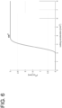
- shows, in another example, an acceleration-dependent correction of the focus position as a cutting parameter with a sine function as the base and exponent and
- Fig. 7
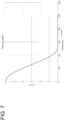
- shows a further example of a speed-based correction of the gas pressure as a cutting parameter;
- Fig. 8a
- shows a cutting result without correction of the cutting parameters according to the prior art and
- Fig. 8b
- shows a cutting result with a correction of the cutting parameters according to the invention by using the calculation method and
- Fig. 9
- shows an example of a graphic representation of the speed-dependent change in the focus position.
- The invention relates to a computer-implemented method for correcting cutting parameters for a laser machine L, which is typically operated with a power of over 2 kW. It can be used in particular for cutting metal sheets and pipes.
- The method according to the invention implements an intelligent conversion algorithm for correcting or adapting cutting parameters to increase quality, especially when cutting small radii and corners, in which the setpoint speed of the laser cutting head must be reduced so that sufficient cutting quality can be guaranteed.
- The advantageous technical effect of the method according to the invention was tested in test series by the applicant. A workpiece WS is shown in
Figure 8A that has been cut with non-adapted or corrected cutting parameters, in particular a first cutting parameter data set 1SP. As can be seen inFigure 8A , the cut has melting regions in the corners and radii as well as in the incision. In contrast thereto, the method according to the invention was used inFigure 8B and the cutting parameters were corrected; the workpiece WS was cut with the second cutting parameter data set 2SP calculated by means of a conversion algorithm. As can be seen, the quality is also good in the corners and radii as well as in the first and last cut. According to the invention, this quality can be ensured with constant or even improved performance (time for cutting the parts). -
Figure 1 shows a laser cutting machine L with a nozzle D that is designed to cut, for example, a plate-shaped sheet metal or a metal tube, also called a workpiece WS. The specific structure of the laser machine L is not significant for the implementation of the present invention. Usually, a plurality of sensors, for example in the form ofphotodiodes 4, can be integrated into the laser head, for example to take pictures of the cutting gap to be able to assess the quality of the cutting result based thereon. The laser machine L can comprise a controller C (not shown inFigure 1 ) that is designed to implement external instructions and - possibly parametrised - instructions and to control or regulate the laser cutting process. In the present case, a computing unit RE can be designed to calculate and provide at least some of the external instructions and to transmit them to the controller C for execution. The computing unit RE is an electronic entity that is provided as a node in a network. It can be part of a cloud-based server, for example. The electronic computing unit RE (hereinafter also referred to as computing unit RE for short) comprises a processor P. As shown in more detail inFigure 1 , the computing unit RE comprises a processor P for executing procedures, functions and in particular a conversion algorithm. The computing unit RE is in data exchange with other entities. In particular, an external memory MEM can be provided, which the computing unit RE accesses to call up parameters for the parameterisation of functions for adapting the cutting parameters as well as the respective functions. The respective - preferably parametrised - functions are then loaded onto the computing unit RE and are available there for execution. Furthermore, the computing unit RE is designed to receive additional data sets. The computing unit RE can thus comprise a user interface Ul on which the user can make inputs. For example, a first cutting parameter data set 1SP can be acquired on the user interface UI. Alternatively, the first cutting parameter data set 1DS can also be read out from a memory (for example, a table-like data structure) as a standard parameter data set, for example. The computing unit RE can also be in data exchange with a further control unit CNC to receive, in particular, a cutting plan sp and/or cutting plan-related data. "Cutting plan-related data" are data that are either contained in the cutting plan sp or can be deduced therefrom. The cutting plan-related data include, for example, the feed rate, the acceleration, the curvature ratios of the geometry to be cut, etc. - In a first variant of the invention, the computing unit RE can be designed to extract or calculate a movement profile object bpo from the received data, in particular from the cutting plan sp and possibly standardised, preset cutting parameters. A value for the speed, acceleration and/or jerk (derivation over time) of the drive axes of the laser head for a specific position on the geometry (circumference of the part to be cut) can be stored in the motion profile object bpo. In the movement profile object bpo, a value for a curvature for a point on the cutting geometry can also be stored cumulatively or alternatively. In a variant, a course of the named variables (speed, acceleration, jerk, curvature) over time can also be stored in the movement profile object bpo.
- In a second variant of the invention, the movement profile object bpo can already have been extracted on an entity external to the computing unit, for example on the CNC control. In this case, the movement profile object bpo need not be calculated on the computing unit RE, but can already be read in in processed form via an interface and processed directly.
- After acquiring the first cutting parameter data set 1SP and the extracted movement profile object bpo, the computing unit RE can convert the first cutting parameter data set 1SP into the second cutting parameter data set 2SP using a conversion algorithm using the functions of the parametrised function catalogue. The second cutting parameter data set 2SP functions as a modified CNC code, so to speak, and is transmitted directly to the internal controller C of the laser cutting machine L for controlling the laser cutting machine L (or the axes/axis drives thereof). Thus, the laser cutting machine L is not - as before - operated with the specifications of the CNC control, but with a modified code that comprises corrected setting values that are encoded in the second cutting parameter data set 2SP.
-
Figure 2 shows a sequence of the calculation method according to the invention in different embodiments (represented in the figure by dotted circles). - After the start of the method, the first cutting parameter data set 1SP is acquired in step S1. In step S2, the movement profile object bpo is extracted. In a first variant of the invention, the conversion algorithm can then be carried out in step S4. The method can then be ended. In a second variant of the invention, a material property of the material to be cut can optionally be acquired in step S3. In this method step it can be specified, for example, how thick the material to be cut (for example sheet metal) is and what type of material it is (for example, aluminium or steel, etc.). These aforementioned variables for the material property can then be taken into account by the conversion algorithm for calculating the second cutting parameter data set 2SP. The corrected or adapted cutting parameter data set, namely the second cutting parameter data set 2SP, can thus be matched even better to the respective application.
- In principle, the sequence of the method steps acquisition of the first cutting parameter data set S1, extraction S2 and acquisition of the material property S3 is not fixed and can also be varied so that the method steps can be carried out in a different sequence (for example S2, S3, S1) or even in parallel.
- In a preferred embodiment, it is provided that the calculated second cutting parameter data set 2SP is transmitted directly and automatically in step S5 to the controller C of the laser cutting machine L for control and/or regulation. However, this step is optional and is therefore shown in dotted lines in
Fig. 2 . In a variant of the invention, however, it can be provided that the calculated second cutting parameter data set 2SP is fed to a validation process in that it is output on a user interface UI and, during validation, a validation signal is acquired on the user interface UI, which indicates the validation of the corrected cutting parameter data set. In this case, the second cutting parameter data set 2SP is only transmitted to the controller C after the validation signal has been acquired, so that the security of the correction method can be increased. - A possible structural design of the laser cutting system is shown in
Figure 3 . In this variant, the electronic computing unit RE is connected to the laser cutting machine L as an external entity via a data connection. The computing unit RE can be deployed, for example, on a cloud-based server ("cloud" inFigure 3 ) which is connected to the laser cutting machine L via an internet connection. In this respect, the embodiment shown inFigure 3 agrees with that described in more detail inFigure 1 . The electronic computing unit RE serves, as described, to calculate the second cutting parameter data set 2SP, which is transmitted directly to the controller C of the laser cutting machine L via the data connection. In this case, the computing unit RE can be implemented, so to speak, between the CNC control CNC and the controller C internal to the laser machine. Alternatively, it is also possible to implement the computing unit RE on the control CNC. - In comparison to
Figure 3 ,Figure 4 shows an alternative embodiment. In this case, the computing unit RE is installed directly on the controller C of the laser cutting machine L. The computing unit RE and/or the controller C can optionally be in data exchange with an external control CNC, in particular to receive control data. - As already mentioned above, the conversion algorithm is based on functions of the function catalogue. The functions can be linear or trigonometric. In other embodiments of the invention, other types of functions can be selected. For example, the conversion algorithm can determine the speed-dependent focus position using a sine function as the base and exponentε Z
0 = 2 as follows:
- For focus positions that are linearly dependent on the acceleration, the conversion algorithm can access the following function of the function catalogue:

Fig. 5 . Lower accelerations do not lead to any additional change. Example with
- The linear relationship is shown graphically as an example in
Figure 5 , where the acceleration on the abscissa and the adapted focus position on the ordinate fz0 (x) is shown. - For the acceleration-dependent correction of the focus position, the conversion algorithm can calculate, for example, using a sine function as the base and exponent ε Z
0 = 4 as follows:
-
Figure 6 shows an example of the speed-based adaptation of the focus position fz0 (x) with
- For the speed-dependent change in gas pressure, the conversion algorithm can calculate, for example, using a sine function as the base and exponent εp
H = 3 as follows:
- An example is shown graphically in
Figure 7 , wherein the cutting speed on the abscissa vc and the optimised or adapted focus position plotted on the ordinate as a function of the cutting speed. - Corresponding graphs result when the gas pressure is adjusted as a function of the acceleration or the speed by means of the conversion algorithm.
- In further embodiments of the invention, more complex functions and combinations of speed, acceleration and curvature-dependent adjustments can be used:

-
Fig. 9 shows again in which situations an adaptation or correction of the cutting parameters is to be carried out using the example of the focus position (also representing the other dynamic cutting parameters). The conversion algorithm can preferably scale depending on the material and sheet metal thickness.Fig. 9 shows that the focus position is corrected to the maximum when the ratio of the current feed rate to the maximum feed rate is zero or very low, that is, when a trajectory section can be moved much slower than the maximum possible due to the feed rate. If the cutting speed vc corresponds to the maximum feed rate vc = Fmax, then the focus position is not adapted, i.e.,Δz 0 /z 0 max is zero. - Finally, it should be noted that the description of the invention and the exemplary embodiments are not to be understood as limiting in terms of a particular physical realisation of the invention. All of the features explained and shown in connection with individual embodiments of the invention can be provided in different combinations in the object according to the invention to simultaneously realise the advantageous effects thereof.
- The scope of protection of the present invention is given by the following claims and is not limited by the features illustrated in the description or shown in the figures.
- It is particularly obvious to a person skilled in the art that the invention can be used not only for settings of certain process parameters, such as the focus position, but also for other process parameters, for example, such as for adjusting or correcting the gas pressure. Furthermore, the components of the device or computing unit can be produced so as to be distributed over a plurality of physical products.
Claims (13)
- A computer-implemented method for calculating a second cutting parameter data set (2SP) for controlling and/or regulating a laser cutting process for cutting metal sheets of a laser cutting machine (L) during the laser cutting of components (WS), having the following method steps, which are carried out on an electronic computing unit (RE):- acquisition (S1) of a first cutting parameter data set (1SP);the computer-implemented method being characterised by the following steps:- extraction (S2) of a movement profile object (bpo) with data relating to the movement to be performed by a laser cutting head and/or data relating to the geometry to be cut, in particular data on the curvature and/or radii of the contour to be cut;- execution (S4) of a conversion algorithm during cutting to dynamically adjust the cutting parameters, said conversion algorithm is stored loadable and/or executable in a memory (MEM) of the electronic computing unit, to calculate and provide the second cutting parameter data set (2SP) from the acquired first cutting parameter data set (1SP) by using transformation rules that are based on a function catalogue which can be stored in an external or internal memory, wherein the second cutting parameter data set (2SP) is calculated as a function of the extracted movement profile object (bpo)- wherein the first cutting parameter data set (1SP) and/or second cutting parameter data set (2SP) comprises dynamic cutting parameters, namely in particular cutting speed, focus position, pulse pattern, nozzle distance, gas pressure, laser power, beam parameter product/BPP and/or focus diameter;- wherein said conversion algorithm calculates a dedicated function for each of the dynamic cutting parameters from a set of functions stored in the memory (MEM).
- The method according to claim 1, wherein the method further comprises:- acquisition (S3) of a material property of the component (WS) to be cut, in particular a sheet metal thickness and/or a material type;- wherein the conversion algorithm for calculating the second cutting parameter data set takes into account the acquired material property, in particular the sheet metal thickness and/or the material type.
- The method according to one of the preceding claims, in which the movement profile object (bpo) indicates a value for a speed, an acceleration and/or a jerk and/or a curvature for a point on a cutting geometry or a course of the aforementioned variables over time.
- The method according to the immediately preceding claim, in which the set of functions can be parametrised.
- The method according to one of the preceding claims, in which the provided second cutting parameter data set (2SP) is transmitted directly to a controller (C) on the laser cutting machine (L) for controlling and/or regulating the laser cutting process.
- The method according to one of the preceding claims, in which the conversion algorithm is only executed when preconfigurable change conditions are met, in particular when the movement profile object (bpo) exceeds or falls below predetermined limit values.
- The method according to one of the preceding claims, in which the conversion algorithm is implemented as a linear or trigonometric function.
- The method according to one of the preceding claims, in which the conversion algorithm calculates the second cutting parameter data set (2SP) dynamically for each point or for sections of a trajectory.
- The method according to one of the preceding claims, in which an acceleration and/or jerk profile is calculated that serves as an input variable in the conversion algorithm.
- A computer program having computer program code for performing all method steps of the previously claimed method when the computer program is executed on a computer, an electronic entity and/or a computing unit (RE).
- An electronic computing unit (RE) for calculating a second cutting parameter data set (2SP) for controlling and/or regulating a laser cutting process for cutting metal sheets of a laser cutting machine (L) during the laser cutting of components (WS), having:- an interface (UI) for acquiring a first cutting parameter data set (1SP),the computing unit (RE) being characterised by:- a processor (P) that is designed- to extract a movement profile object (bpo) with data relating to the movement to be performed by a laser cutting head and/or data relating to the geometry to be cut, in particular data on the curvature and/or radii of the contour to be cut;- to execute a conversion algorithm during cutting to adjust the cutting parameters, said conversion algorithm is stored loadable and/or executable in a memory (MEM) of the electronic computing unit (RE) to calculate and provide the second cutting parameter data set (2SP) from the acquired first cutting parameter data set (1SP) by using transformation rules that are based on a function catalogue which can be stored in an external or internal memory, wherein the second cutting parameter data set (2SP) is calculated as a function of the extracted motion profile object (bpo) and- to execute a conversion algorithm which calculates a dedicated function for each of the dynamic cutting parameters from a set of functions stored in the memory (MEM);- wherein the first cutting parameter data set (1SP) and/or second cutting parameter data set (2SP) comprises dynamic cutting parameters, namely in particular cutting speed, focus position, pulse pattern, nozzle distance, gas pressure, laser power, beam parameter product/BPP and/or focus diameter.
- A laser cutting system, having:- a laser cutting machine (L),- a controller (C, RE),the system being characterised by:- an electronic computing unit (RE) according to claim 11, wherein the laser cutting machine (L) is controlled and/or regulated by the controller (C, RE).
- The laser cutting system according to claim 12, wherein the electronic computing unit (RE) is implemented on the controller (C).
Applications Claiming Priority (2)
| Application Number | Priority Date | Filing Date | Title |
|---|---|---|---|
| EP20202245.5A EP3984688A1 (en) | 2020-10-16 | 2020-10-16 | Method, computer program and laser cutting system for smart corner cutting |
| PCT/EP2021/078616 WO2022079240A1 (en) | 2020-10-16 | 2021-10-15 | Method, computer program and laser cutting system for smart corner cutting |
Publications (2)
| Publication Number | Publication Date |
|---|---|
| EP4228849A1 EP4228849A1 (en) | 2023-08-23 |
| EP4228849B1 true EP4228849B1 (en) | 2024-12-18 |
Family
ID=73029821
Family Applications (2)
| Application Number | Title | Priority Date | Filing Date |
|---|---|---|---|
| EP20202245.5A Withdrawn EP3984688A1 (en) | 2020-10-16 | 2020-10-16 | Method, computer program and laser cutting system for smart corner cutting |
| EP21794141.8A Active EP4228849B1 (en) | 2020-10-16 | 2021-10-15 | Method, computer program and laser cutting system for smart corner cutting |
Family Applications Before (1)
| Application Number | Title | Priority Date | Filing Date |
|---|---|---|---|
| EP20202245.5A Withdrawn EP3984688A1 (en) | 2020-10-16 | 2020-10-16 | Method, computer program and laser cutting system for smart corner cutting |
Country Status (5)
| Country | Link |
|---|---|
| US (1) | US11980966B2 (en) |
| EP (2) | EP3984688A1 (en) |
| JP (1) | JP7382537B2 (en) |
| CN (2) | CN120619606A (en) |
| WO (1) | WO2022079240A1 (en) |
Families Citing this family (6)
| Publication number | Priority date | Publication date | Assignee | Title |
|---|---|---|---|---|
| DE102022101429A1 (en) | 2022-01-21 | 2023-07-27 | TRUMPF Werkzeugmaschinen SE + Co. KG | Beam cutting process, computer program and beam cutting system |
| CN117532177B (en) * | 2023-12-25 | 2024-06-04 | 惠州兴通成机电技术有限公司 | Laser cutting system and method for bevel lampshade |
| CN118646988B (en) * | 2024-08-15 | 2024-11-22 | 宁波富声达电机有限公司 | A speaker diaphragm processing method, system, intelligent terminal and storage medium |
| CN118884899B (en) * | 2024-09-30 | 2025-01-14 | 深圳市常丰激光刀模有限公司 | Intelligent mold production control method, device, equipment and storage medium |
| CN119212229A (en) * | 2024-11-27 | 2024-12-27 | 深圳市盛鸿运科技有限公司 | A reinforcement processing method and device for flexible circuit board |
| CN119689975B (en) * | 2024-12-31 | 2025-09-09 | 昆山冠业达精密工业有限公司 | Numerical control cutting path optimization method and system for special-shaped parts |
Family Cites Families (30)
| Publication number | Priority date | Publication date | Assignee | Title |
|---|---|---|---|---|
| JPH04123884A (en) * | 1990-09-14 | 1992-04-23 | Mitsubishi Electric Corp | Follow-up controller of three dimensional laser beam machine |
| JPH067973A (en) * | 1992-06-25 | 1994-01-18 | Fanuc Ltd | Laser beam machine |
| DE4404141A1 (en) * | 1994-02-09 | 1995-08-10 | Fraunhofer Ges Forschung | Device and method for laser beam shaping, especially in laser beam surface processing |
| JP3159593B2 (en) * | 1994-02-28 | 2001-04-23 | 三菱電機株式会社 | Laser processing method and apparatus |
| EP0991493B1 (en) * | 1997-06-24 | 2004-07-28 | AMADA COMPANY, Ltd. | Support system for laser beam machine, and laser beam machine including the same |
| DE102011001474A1 (en) * | 2011-03-22 | 2012-09-27 | Carl Zeiss Microimaging Gmbh | Laser microdissection method and laser microdissection device |
| WO2014107274A1 (en) * | 2012-12-20 | 2014-07-10 | 3M Innovative Properties Company | Material processing low-inertia laser scanning end-effector manipulation |
| US11440141B2 (en) * | 2013-09-13 | 2022-09-13 | Trumpf Werkzeugmaschinen Gmbh + Co. Kg | Devices and methods for monitoring, in particular for regulating, a cutting process |
| KR101682269B1 (en) * | 2013-09-25 | 2016-12-05 | 주식회사 엘지화학 | Laser Cutting apparatus and cutting method of the same |
| WO2015072107A1 (en) * | 2013-11-15 | 2015-05-21 | パナソニックIpマネジメント株式会社 | Laser welding condition determination method and laser welding device |
| EP2883647B1 (en) | 2013-12-12 | 2019-05-29 | Bystronic Laser AG | Method for configuring a laser machining device |
| DE102014212682A1 (en) * | 2014-07-01 | 2016-01-07 | Trumpf Werkzeugmaschinen Gmbh + Co. Kg | Method and device for determining a type of material and / or a surface finish of a workpiece |
| KR102448778B1 (en) * | 2014-08-20 | 2022-09-29 | 코닝 인코포레이티드 | Apparatus and method for yielding high edge strength when cutting thin flexible glass |
| CN104607805B (en) * | 2015-01-12 | 2016-07-06 | 飞虎激光科技有限公司 | A kind of corner laser cutting method |
| JP6339603B2 (en) * | 2016-01-28 | 2018-06-06 | ファナック株式会社 | Machine learning apparatus, laser apparatus, and machine learning method for learning laser processing start condition |
| CN105834578B (en) * | 2016-04-07 | 2017-12-01 | 武汉菲仕运动控制系统有限公司 | A kind of Biaxial synchronous laser cutting machine control system |
| DE102016220807B3 (en) * | 2016-10-24 | 2018-03-29 | Trumpf Werkzeugmaschinen Gmbh + Co. Kg | Method for cutting a workpiece by means of a laser beam |
| CN110785257B (en) * | 2017-06-29 | 2021-08-27 | 松下知识产权经营株式会社 | Laser processing system and control method of laser processing system |
| JP6595558B2 (en) * | 2017-10-30 | 2019-10-23 | ファナック株式会社 | Laser processing system |
| CN111050984B (en) * | 2018-03-26 | 2022-03-25 | 松下知识产权经营株式会社 | Laser cutting apparatus and laser cutting method |
| CN109048091B (en) * | 2018-07-17 | 2020-12-25 | 大族激光科技产业集团股份有限公司 | Laser cutting speed planning method and device, storage medium and computer equipment |
| US20200101566A1 (en) * | 2018-09-27 | 2020-04-02 | Ipg Photonics Corporation | System and Method for Visualizing Laser Energy Distributions Provided by Different Near Field Scanning Patterns |
| DE102018216873A1 (en) * | 2018-10-01 | 2020-04-02 | Trumpf Werkzeugmaschinen Gmbh + Co. Kg | Method and device for machining a workpiece |
| JP6795565B2 (en) * | 2018-10-11 | 2020-12-02 | ファナック株式会社 | Laser machining system |
| JP7028820B6 (en) * | 2019-03-18 | 2023-12-19 | ファナック株式会社 | Laser processing method for cutting workpieces |
| JP6989554B2 (en) * | 2019-03-18 | 2022-01-05 | ファナック株式会社 | Laser processing machine that cuts workpieces |
| CN110369884A (en) * | 2019-08-21 | 2019-10-25 | 奔腾楚天激光(武汉)有限公司 | A kind of turning pulse cutting process of processing thick carbon steel plate right angle processing |
| CN110919212A (en) * | 2019-12-12 | 2020-03-27 | 佛山市宏石激光技术有限公司 | Power control method and system of laser cutting machine |
| DE102020112116A1 (en) * | 2020-05-05 | 2021-11-11 | Precitec Gmbh & Co. Kg | Method for analyzing a laser machining process, system for analyzing a laser machining process and laser machining system with such a system |
| CN111571039A (en) * | 2020-06-23 | 2020-08-25 | 济南九泰企业管理咨询有限公司 | Laser cutting device and method capable of avoiding overburning |
-
2020
- 2020-10-16 EP EP20202245.5A patent/EP3984688A1/en not_active Withdrawn
-
2021
- 2021-10-15 CN CN202510580319.4A patent/CN120619606A/en active Pending
- 2021-10-15 WO PCT/EP2021/078616 patent/WO2022079240A1/en not_active Ceased
- 2021-10-15 US US18/248,742 patent/US11980966B2/en active Active
- 2021-10-15 CN CN202180069107.XA patent/CN116323085A/en active Pending
- 2021-10-15 JP JP2023522988A patent/JP7382537B2/en active Active
- 2021-10-15 EP EP21794141.8A patent/EP4228849B1/en active Active
Also Published As
| Publication number | Publication date |
|---|---|
| WO2022079240A1 (en) | 2022-04-21 |
| WO2022079240A4 (en) | 2022-06-09 |
| EP4228849A1 (en) | 2023-08-23 |
| CN116323085A (en) | 2023-06-23 |
| JP7382537B2 (en) | 2023-11-16 |
| JP2023541329A (en) | 2023-09-29 |
| CN120619606A (en) | 2025-09-12 |
| EP3984688A1 (en) | 2022-04-20 |
| US11980966B2 (en) | 2024-05-14 |
| US20230405710A1 (en) | 2023-12-21 |
Similar Documents
| Publication | Publication Date | Title |
|---|---|---|
| US11980966B2 (en) | Method, computer program and laser cutting system for smart corner cutting | |
| US12285820B2 (en) | Method, control unit and laser cutting system for combined path and laser process planning for highly dynamic real-time systems | |
| TWI649648B (en) | Processing machine thermal compensation control system and method thereof | |
| DE102012109867B4 (en) | Control device for a laser beam machining | |
| US5923561A (en) | Process of generating a succession of discrete points defining cutter path, by calculating a space interval of discrete points | |
| US20160202688A1 (en) | Automatic parameter adjustment device for adjusting parameter corresponding to processing condition | |
| US20180299857A1 (en) | Control device for machine tool performing oscillation cutting | |
| WO2002003155A1 (en) | Apparatus and method for machining simulation for nc machining | |
| US6539275B1 (en) | Machine controller and process with two-step interpolation | |
| CN118905724B (en) | Data-driven self-adaptive wall thickness control method and system for rocket tank bottom mirror milling | |
| EP4120955B1 (en) | Dental machining system for generating process parameters of the machining | |
| CN114637256B (en) | Fly-cutting control method, device and system, electronic equipment and storage medium | |
| EP0566747B1 (en) | Method of controlling servomotors | |
| JPH0752365B2 (en) | Numerical control device | |
| KR970002259B1 (en) | Servo motor control method | |
| CN106774163A (en) | High-precision three-dimensional contour outline control method and device | |
| EP4162332B1 (en) | Device and method for machining a workpiece | |
| JPH0777692B2 (en) | Thread cutting method | |
| JP3520142B2 (en) | Quadrant projection correction parameter determination device | |
| JPH0947941A (en) | NC machine tool feed speed control method and device | |
| CN115916451A (en) | Method, control unit and laser cutting system for combined path and laser process planning for highly dynamic real-time systems | |
| JP6923736B2 (en) | Numerical control device | |
| WO2023026484A1 (en) | Evaluation program creation device and computer-readable recording medium recording program | |
| JPH0769732B2 (en) | Numerical control method | |
| Tounsi et al. | Enhancement of productivity by intelligent programming of feed rate in 3-axis milling |
Legal Events
| Date | Code | Title | Description |
|---|---|---|---|
| STAA | Information on the status of an ep patent application or granted ep patent |
Free format text: STATUS: UNKNOWN |
|
| STAA | Information on the status of an ep patent application or granted ep patent |
Free format text: STATUS: THE INTERNATIONAL PUBLICATION HAS BEEN MADE |
|
| PUAI | Public reference made under article 153(3) epc to a published international application that has entered the european phase |
Free format text: ORIGINAL CODE: 0009012 |
|
| STAA | Information on the status of an ep patent application or granted ep patent |
Free format text: STATUS: REQUEST FOR EXAMINATION WAS MADE |
|
| 17P | Request for examination filed |
Effective date: 20230215 |
|
| AK | Designated contracting states |
Kind code of ref document: A1 Designated state(s): AL AT BE BG CH CY CZ DE DK EE ES FI FR GB GR HR HU IE IS IT LI LT LU LV MC MK MT NL NO PL PT RO RS SE SI SK SM TR |
|
| DAV | Request for validation of the european patent (deleted) | ||
| DAX | Request for extension of the european patent (deleted) | ||
| GRAP | Despatch of communication of intention to grant a patent |
Free format text: ORIGINAL CODE: EPIDOSNIGR1 |
|
| STAA | Information on the status of an ep patent application or granted ep patent |
Free format text: STATUS: GRANT OF PATENT IS INTENDED |
|
| GRAJ | Information related to disapproval of communication of intention to grant by the applicant or resumption of examination proceedings by the epo deleted |
Free format text: ORIGINAL CODE: EPIDOSDIGR1 |
|
| STAA | Information on the status of an ep patent application or granted ep patent |
Free format text: STATUS: REQUEST FOR EXAMINATION WAS MADE |
|
| INTG | Intention to grant announced |
Effective date: 20240611 |
|
| INTC | Intention to grant announced (deleted) | ||
| GRAP | Despatch of communication of intention to grant a patent |
Free format text: ORIGINAL CODE: EPIDOSNIGR1 |
|
| STAA | Information on the status of an ep patent application or granted ep patent |
Free format text: STATUS: GRANT OF PATENT IS INTENDED |
|
| INTG | Intention to grant announced |
Effective date: 20240816 |
|
| GRAS | Grant fee paid |
Free format text: ORIGINAL CODE: EPIDOSNIGR3 |
|
| GRAA | (expected) grant |
Free format text: ORIGINAL CODE: 0009210 |
|
| STAA | Information on the status of an ep patent application or granted ep patent |
Free format text: STATUS: THE PATENT HAS BEEN GRANTED |
|
| AK | Designated contracting states |
Kind code of ref document: B1 Designated state(s): AL AT BE BG CH CY CZ DE DK EE ES FI FR GB GR HR HU IE IS IT LI LT LU LV MC MK MT NL NO PL PT RO RS SE SI SK SM TR |
|
| REG | Reference to a national code |
Ref country code: CH Ref legal event code: EP |
|
| P01 | Opt-out of the competence of the unified patent court (upc) registered |
Free format text: CASE NUMBER: APP_63592/2024 Effective date: 20241129 |
|
| REG | Reference to a national code |
Ref country code: DE Ref legal event code: R096 Ref document number: 602021023640 Country of ref document: DE |
|
| REG | Reference to a national code |
Ref country code: IE Ref legal event code: FG4D |
|
| REG | Reference to a national code |
Ref country code: LT Ref legal event code: MG9D |
|
| PG25 | Lapsed in a contracting state [announced via postgrant information from national office to epo] |
Ref country code: HR Free format text: LAPSE BECAUSE OF FAILURE TO SUBMIT A TRANSLATION OF THE DESCRIPTION OR TO PAY THE FEE WITHIN THE PRESCRIBED TIME-LIMIT Effective date: 20241218 |
|
| PG25 | Lapsed in a contracting state [announced via postgrant information from national office to epo] |
Ref country code: FI Free format text: LAPSE BECAUSE OF FAILURE TO SUBMIT A TRANSLATION OF THE DESCRIPTION OR TO PAY THE FEE WITHIN THE PRESCRIBED TIME-LIMIT Effective date: 20241218 |
|
| PG25 | Lapsed in a contracting state [announced via postgrant information from national office to epo] |
Ref country code: BG Free format text: LAPSE BECAUSE OF FAILURE TO SUBMIT A TRANSLATION OF THE DESCRIPTION OR TO PAY THE FEE WITHIN THE PRESCRIBED TIME-LIMIT Effective date: 20241218 |
|
| PG25 | Lapsed in a contracting state [announced via postgrant information from national office to epo] |
Ref country code: NO Free format text: LAPSE BECAUSE OF FAILURE TO SUBMIT A TRANSLATION OF THE DESCRIPTION OR TO PAY THE FEE WITHIN THE PRESCRIBED TIME-LIMIT Effective date: 20250318 |
|
| REG | Reference to a national code |
Ref country code: NL Ref legal event code: MP Effective date: 20241218 |
|
| PG25 | Lapsed in a contracting state [announced via postgrant information from national office to epo] |
Ref country code: LV Free format text: LAPSE BECAUSE OF FAILURE TO SUBMIT A TRANSLATION OF THE DESCRIPTION OR TO PAY THE FEE WITHIN THE PRESCRIBED TIME-LIMIT Effective date: 20241218 Ref country code: GR Free format text: LAPSE BECAUSE OF FAILURE TO SUBMIT A TRANSLATION OF THE DESCRIPTION OR TO PAY THE FEE WITHIN THE PRESCRIBED TIME-LIMIT Effective date: 20250319 |
|
| PG25 | Lapsed in a contracting state [announced via postgrant information from national office to epo] |
Ref country code: RS Free format text: LAPSE BECAUSE OF FAILURE TO SUBMIT A TRANSLATION OF THE DESCRIPTION OR TO PAY THE FEE WITHIN THE PRESCRIBED TIME-LIMIT Effective date: 20250318 |
|
| PG25 | Lapsed in a contracting state [announced via postgrant information from national office to epo] |
Ref country code: NL Free format text: LAPSE BECAUSE OF FAILURE TO SUBMIT A TRANSLATION OF THE DESCRIPTION OR TO PAY THE FEE WITHIN THE PRESCRIBED TIME-LIMIT Effective date: 20241218 |
|
| REG | Reference to a national code |
Ref country code: AT Ref legal event code: MK05 Ref document number: 1751876 Country of ref document: AT Kind code of ref document: T Effective date: 20241218 |
|
| PG25 | Lapsed in a contracting state [announced via postgrant information from national office to epo] |
Ref country code: SM Free format text: LAPSE BECAUSE OF FAILURE TO SUBMIT A TRANSLATION OF THE DESCRIPTION OR TO PAY THE FEE WITHIN THE PRESCRIBED TIME-LIMIT Effective date: 20241218 |
|
| PG25 | Lapsed in a contracting state [announced via postgrant information from national office to epo] |
Ref country code: PL Free format text: LAPSE BECAUSE OF FAILURE TO SUBMIT A TRANSLATION OF THE DESCRIPTION OR TO PAY THE FEE WITHIN THE PRESCRIBED TIME-LIMIT Effective date: 20241218 |
|
| PG25 | Lapsed in a contracting state [announced via postgrant information from national office to epo] |
Ref country code: ES Free format text: LAPSE BECAUSE OF FAILURE TO SUBMIT A TRANSLATION OF THE DESCRIPTION OR TO PAY THE FEE WITHIN THE PRESCRIBED TIME-LIMIT Effective date: 20241218 |
|
| PG25 | Lapsed in a contracting state [announced via postgrant information from national office to epo] |
Ref country code: IS Free format text: LAPSE BECAUSE OF FAILURE TO SUBMIT A TRANSLATION OF THE DESCRIPTION OR TO PAY THE FEE WITHIN THE PRESCRIBED TIME-LIMIT Effective date: 20250418 |
|
| PG25 | Lapsed in a contracting state [announced via postgrant information from national office to epo] |
Ref country code: PT Free format text: LAPSE BECAUSE OF FAILURE TO SUBMIT A TRANSLATION OF THE DESCRIPTION OR TO PAY THE FEE WITHIN THE PRESCRIBED TIME-LIMIT Effective date: 20250421 |
|
| PG25 | Lapsed in a contracting state [announced via postgrant information from national office to epo] |
Ref country code: EE Free format text: LAPSE BECAUSE OF FAILURE TO SUBMIT A TRANSLATION OF THE DESCRIPTION OR TO PAY THE FEE WITHIN THE PRESCRIBED TIME-LIMIT Effective date: 20241218 |
|
| PG25 | Lapsed in a contracting state [announced via postgrant information from national office to epo] |
Ref country code: AT Free format text: LAPSE BECAUSE OF FAILURE TO SUBMIT A TRANSLATION OF THE DESCRIPTION OR TO PAY THE FEE WITHIN THE PRESCRIBED TIME-LIMIT Effective date: 20241218 Ref country code: RO Free format text: LAPSE BECAUSE OF FAILURE TO SUBMIT A TRANSLATION OF THE DESCRIPTION OR TO PAY THE FEE WITHIN THE PRESCRIBED TIME-LIMIT Effective date: 20241218 |
|
| PG25 | Lapsed in a contracting state [announced via postgrant information from national office to epo] |
Ref country code: SK Free format text: LAPSE BECAUSE OF FAILURE TO SUBMIT A TRANSLATION OF THE DESCRIPTION OR TO PAY THE FEE WITHIN THE PRESCRIBED TIME-LIMIT Effective date: 20241218 |
|
| PG25 | Lapsed in a contracting state [announced via postgrant information from national office to epo] |
Ref country code: CZ Free format text: LAPSE BECAUSE OF FAILURE TO SUBMIT A TRANSLATION OF THE DESCRIPTION OR TO PAY THE FEE WITHIN THE PRESCRIBED TIME-LIMIT Effective date: 20241218 |
|
| PG25 | Lapsed in a contracting state [announced via postgrant information from national office to epo] |
Ref country code: SE Free format text: LAPSE BECAUSE OF FAILURE TO SUBMIT A TRANSLATION OF THE DESCRIPTION OR TO PAY THE FEE WITHIN THE PRESCRIBED TIME-LIMIT Effective date: 20241218 |
|
| REG | Reference to a national code |
Ref country code: DE Ref legal event code: R097 Ref document number: 602021023640 Country of ref document: DE |
|
| PG25 | Lapsed in a contracting state [announced via postgrant information from national office to epo] |
Ref country code: DK Free format text: LAPSE BECAUSE OF FAILURE TO SUBMIT A TRANSLATION OF THE DESCRIPTION OR TO PAY THE FEE WITHIN THE PRESCRIBED TIME-LIMIT Effective date: 20241218 |
|
| PGFP | Annual fee paid to national office [announced via postgrant information from national office to epo] |
Ref country code: IT Payment date: 20250922 Year of fee payment: 5 |
|
| PGFP | Annual fee paid to national office [announced via postgrant information from national office to epo] |
Ref country code: GB Payment date: 20250904 Year of fee payment: 5 |
|
| PLBE | No opposition filed within time limit |
Free format text: ORIGINAL CODE: 0009261 |
|
| STAA | Information on the status of an ep patent application or granted ep patent |
Free format text: STATUS: NO OPPOSITION FILED WITHIN TIME LIMIT |
|
| REG | Reference to a national code |
Ref country code: CH Ref legal event code: L10 Free format text: ST27 STATUS EVENT CODE: U-0-0-L10-L00 (AS PROVIDED BY THE NATIONAL OFFICE) Effective date: 20251029 |
|
| REG | Reference to a national code |
Ref country code: CH Ref legal event code: U11 Free format text: ST27 STATUS EVENT CODE: U-0-0-U10-U11 (AS PROVIDED BY THE NATIONAL OFFICE) Effective date: 20251101 |
|
| 26N | No opposition filed |
Effective date: 20250919 |
|
| PGFP | Annual fee paid to national office [announced via postgrant information from national office to epo] |
Ref country code: DE Payment date: 20250902 Year of fee payment: 5 |
|
| PGFP | Annual fee paid to national office [announced via postgrant information from national office to epo] |
Ref country code: CH Payment date: 20251101 Year of fee payment: 5 |