EP4228052A1 - Battery pack, control method for battery pack, and vehicle - Google Patents
Battery pack, control method for battery pack, and vehicle Download PDFInfo
- Publication number
- EP4228052A1 EP4228052A1 EP21908440.7A EP21908440A EP4228052A1 EP 4228052 A1 EP4228052 A1 EP 4228052A1 EP 21908440 A EP21908440 A EP 21908440A EP 4228052 A1 EP4228052 A1 EP 4228052A1
- Authority
- EP
- European Patent Office
- Prior art keywords
- signal
- charge
- liquid leakage
- module
- switch module
- Prior art date
- Legal status (The legal status is an assumption and is not a legal conclusion. Google has not performed a legal analysis and makes no representation as to the accuracy of the status listed.)
- Pending
Links
Images


Classifications
-
- B—PERFORMING OPERATIONS; TRANSPORTING
- B60—VEHICLES IN GENERAL
- B60L—PROPULSION OF ELECTRICALLY-PROPELLED VEHICLES; SUPPLYING ELECTRIC POWER FOR AUXILIARY EQUIPMENT OF ELECTRICALLY-PROPELLED VEHICLES; ELECTRODYNAMIC BRAKE SYSTEMS FOR VEHICLES IN GENERAL; MAGNETIC SUSPENSION OR LEVITATION FOR VEHICLES; MONITORING OPERATING VARIABLES OF ELECTRICALLY-PROPELLED VEHICLES; ELECTRIC SAFETY DEVICES FOR ELECTRICALLY-PROPELLED VEHICLES
- B60L3/00—Electric devices on electrically-propelled vehicles for safety purposes; Monitoring operating variables, e.g. speed, deceleration or energy consumption
- B60L3/0023—Detecting, eliminating, remedying or compensating for drive train abnormalities, e.g. failures within the drive train
- B60L3/0046—Detecting, eliminating, remedying or compensating for drive train abnormalities, e.g. failures within the drive train relating to electric energy storage systems, e.g. batteries or capacitors
-
- B—PERFORMING OPERATIONS; TRANSPORTING
- B60—VEHICLES IN GENERAL
- B60L—PROPULSION OF ELECTRICALLY-PROPELLED VEHICLES; SUPPLYING ELECTRIC POWER FOR AUXILIARY EQUIPMENT OF ELECTRICALLY-PROPELLED VEHICLES; ELECTRODYNAMIC BRAKE SYSTEMS FOR VEHICLES IN GENERAL; MAGNETIC SUSPENSION OR LEVITATION FOR VEHICLES; MONITORING OPERATING VARIABLES OF ELECTRICALLY-PROPELLED VEHICLES; ELECTRIC SAFETY DEVICES FOR ELECTRICALLY-PROPELLED VEHICLES
- B60L3/00—Electric devices on electrically-propelled vehicles for safety purposes; Monitoring operating variables, e.g. speed, deceleration or energy consumption
- B60L3/04—Cutting off the power supply under fault conditions
-
- B—PERFORMING OPERATIONS; TRANSPORTING
- B60—VEHICLES IN GENERAL
- B60L—PROPULSION OF ELECTRICALLY-PROPELLED VEHICLES; SUPPLYING ELECTRIC POWER FOR AUXILIARY EQUIPMENT OF ELECTRICALLY-PROPELLED VEHICLES; ELECTRODYNAMIC BRAKE SYSTEMS FOR VEHICLES IN GENERAL; MAGNETIC SUSPENSION OR LEVITATION FOR VEHICLES; MONITORING OPERATING VARIABLES OF ELECTRICALLY-PROPELLED VEHICLES; ELECTRIC SAFETY DEVICES FOR ELECTRICALLY-PROPELLED VEHICLES
- B60L50/00—Electric propulsion with power supplied within the vehicle
- B60L50/50—Electric propulsion with power supplied within the vehicle using propulsion power supplied by batteries or fuel cells
- B60L50/60—Electric propulsion with power supplied within the vehicle using propulsion power supplied by batteries or fuel cells using power supplied by batteries
- B60L50/64—Constructional details of batteries specially adapted for electric vehicles
-
- B—PERFORMING OPERATIONS; TRANSPORTING
- B60—VEHICLES IN GENERAL
- B60L—PROPULSION OF ELECTRICALLY-PROPELLED VEHICLES; SUPPLYING ELECTRIC POWER FOR AUXILIARY EQUIPMENT OF ELECTRICALLY-PROPELLED VEHICLES; ELECTRODYNAMIC BRAKE SYSTEMS FOR VEHICLES IN GENERAL; MAGNETIC SUSPENSION OR LEVITATION FOR VEHICLES; MONITORING OPERATING VARIABLES OF ELECTRICALLY-PROPELLED VEHICLES; ELECTRIC SAFETY DEVICES FOR ELECTRICALLY-PROPELLED VEHICLES
- B60L58/00—Methods or circuit arrangements for monitoring or controlling batteries or fuel cells, specially adapted for electric vehicles
-
- G—PHYSICS
- G01—MEASURING; TESTING
- G01M—TESTING STATIC OR DYNAMIC BALANCE OF MACHINES OR STRUCTURES; TESTING OF STRUCTURES OR APPARATUS, NOT OTHERWISE PROVIDED FOR
- G01M3/00—Investigating fluid-tightness of structures
- G01M3/02—Investigating fluid-tightness of structures by using fluid or vacuum
- G01M3/04—Investigating fluid-tightness of structures by using fluid or vacuum by detecting the presence of fluid at the leakage point
- G01M3/16—Investigating fluid-tightness of structures by using fluid or vacuum by detecting the presence of fluid at the leakage point using electric detection means
-
- H—ELECTRICITY
- H01—ELECTRIC ELEMENTS
- H01M—PROCESSES OR MEANS, e.g. BATTERIES, FOR THE DIRECT CONVERSION OF CHEMICAL ENERGY INTO ELECTRICAL ENERGY
- H01M10/00—Secondary cells; Manufacture thereof
- H01M10/42—Methods or arrangements for servicing or maintenance of secondary cells or secondary half-cells
-
- H—ELECTRICITY
- H01—ELECTRIC ELEMENTS
- H01M—PROCESSES OR MEANS, e.g. BATTERIES, FOR THE DIRECT CONVERSION OF CHEMICAL ENERGY INTO ELECTRICAL ENERGY
- H01M10/00—Secondary cells; Manufacture thereof
- H01M10/42—Methods or arrangements for servicing or maintenance of secondary cells or secondary half-cells
- H01M10/4228—Leak testing of cells or batteries
-
- H—ELECTRICITY
- H01—ELECTRIC ELEMENTS
- H01M—PROCESSES OR MEANS, e.g. BATTERIES, FOR THE DIRECT CONVERSION OF CHEMICAL ENERGY INTO ELECTRICAL ENERGY
- H01M10/00—Secondary cells; Manufacture thereof
- H01M10/42—Methods or arrangements for servicing or maintenance of secondary cells or secondary half-cells
- H01M10/425—Structural combination with electronic components, e.g. electronic circuits integrated to the outside of the casing
-
- H—ELECTRICITY
- H01—ELECTRIC ELEMENTS
- H01M—PROCESSES OR MEANS, e.g. BATTERIES, FOR THE DIRECT CONVERSION OF CHEMICAL ENERGY INTO ELECTRICAL ENERGY
- H01M10/00—Secondary cells; Manufacture thereof
- H01M10/42—Methods or arrangements for servicing or maintenance of secondary cells or secondary half-cells
- H01M10/44—Methods for charging or discharging
-
- H—ELECTRICITY
- H01—ELECTRIC ELEMENTS
- H01M—PROCESSES OR MEANS, e.g. BATTERIES, FOR THE DIRECT CONVERSION OF CHEMICAL ENERGY INTO ELECTRICAL ENERGY
- H01M10/00—Secondary cells; Manufacture thereof
- H01M10/42—Methods or arrangements for servicing or maintenance of secondary cells or secondary half-cells
- H01M10/44—Methods for charging or discharging
- H01M10/446—Initial charging measures
-
- H—ELECTRICITY
- H01—ELECTRIC ELEMENTS
- H01M—PROCESSES OR MEANS, e.g. BATTERIES, FOR THE DIRECT CONVERSION OF CHEMICAL ENERGY INTO ELECTRICAL ENERGY
- H01M10/00—Secondary cells; Manufacture thereof
- H01M10/42—Methods or arrangements for servicing or maintenance of secondary cells or secondary half-cells
- H01M10/44—Methods for charging or discharging
- H01M10/448—End of discharge regulating measures
-
- H—ELECTRICITY
- H01—ELECTRIC ELEMENTS
- H01M—PROCESSES OR MEANS, e.g. BATTERIES, FOR THE DIRECT CONVERSION OF CHEMICAL ENERGY INTO ELECTRICAL ENERGY
- H01M10/00—Secondary cells; Manufacture thereof
- H01M10/42—Methods or arrangements for servicing or maintenance of secondary cells or secondary half-cells
- H01M10/46—Accumulators structurally combined with charging apparatus
-
- H—ELECTRICITY
- H01—ELECTRIC ELEMENTS
- H01M—PROCESSES OR MEANS, e.g. BATTERIES, FOR THE DIRECT CONVERSION OF CHEMICAL ENERGY INTO ELECTRICAL ENERGY
- H01M10/00—Secondary cells; Manufacture thereof
- H01M10/42—Methods or arrangements for servicing or maintenance of secondary cells or secondary half-cells
- H01M10/48—Accumulators combined with arrangements for measuring, testing or indicating the condition of cells, e.g. the level or density of the electrolyte
-
- H—ELECTRICITY
- H01—ELECTRIC ELEMENTS
- H01M—PROCESSES OR MEANS, e.g. BATTERIES, FOR THE DIRECT CONVERSION OF CHEMICAL ENERGY INTO ELECTRICAL ENERGY
- H01M50/00—Constructional details or processes of manufacture of the non-active parts of electrochemical cells other than fuel cells, e.g. hybrid cells
- H01M50/20—Mountings; Secondary casings or frames; Racks, modules or packs; Suspension devices; Shock absorbers; Transport or carrying devices; Holders
- H01M50/249—Mountings; Secondary casings or frames; Racks, modules or packs; Suspension devices; Shock absorbers; Transport or carrying devices; Holders specially adapted for aircraft or vehicles, e.g. cars or trains
-
- H—ELECTRICITY
- H01—ELECTRIC ELEMENTS
- H01M—PROCESSES OR MEANS, e.g. BATTERIES, FOR THE DIRECT CONVERSION OF CHEMICAL ENERGY INTO ELECTRICAL ENERGY
- H01M50/00—Constructional details or processes of manufacture of the non-active parts of electrochemical cells other than fuel cells, e.g. hybrid cells
- H01M50/20—Mountings; Secondary casings or frames; Racks, modules or packs; Suspension devices; Shock absorbers; Transport or carrying devices; Holders
- H01M50/258—Modular batteries; Casings provided with means for assembling
-
- H—ELECTRICITY
- H01—ELECTRIC ELEMENTS
- H01M—PROCESSES OR MEANS, e.g. BATTERIES, FOR THE DIRECT CONVERSION OF CHEMICAL ENERGY INTO ELECTRICAL ENERGY
- H01M50/00—Constructional details or processes of manufacture of the non-active parts of electrochemical cells other than fuel cells, e.g. hybrid cells
- H01M50/50—Current conducting connections for cells or batteries
- H01M50/572—Means for preventing undesired use or discharge
- H01M50/574—Devices or arrangements for the interruption of current
-
- H—ELECTRICITY
- H01—ELECTRIC ELEMENTS
- H01M—PROCESSES OR MEANS, e.g. BATTERIES, FOR THE DIRECT CONVERSION OF CHEMICAL ENERGY INTO ELECTRICAL ENERGY
- H01M10/00—Secondary cells; Manufacture thereof
- H01M10/42—Methods or arrangements for servicing or maintenance of secondary cells or secondary half-cells
- H01M10/425—Structural combination with electronic components, e.g. electronic circuits integrated to the outside of the casing
- H01M2010/4271—Battery management systems including electronic circuits, e.g. control of current or voltage to keep battery in healthy state, cell balancing
-
- H—ELECTRICITY
- H01—ELECTRIC ELEMENTS
- H01M—PROCESSES OR MEANS, e.g. BATTERIES, FOR THE DIRECT CONVERSION OF CHEMICAL ENERGY INTO ELECTRICAL ENERGY
- H01M2220/00—Batteries for particular applications
- H01M2220/20—Batteries in motive systems, e.g. vehicle, ship, plane
-
- Y—GENERAL TAGGING OF NEW TECHNOLOGICAL DEVELOPMENTS; GENERAL TAGGING OF CROSS-SECTIONAL TECHNOLOGIES SPANNING OVER SEVERAL SECTIONS OF THE IPC; TECHNICAL SUBJECTS COVERED BY FORMER USPC CROSS-REFERENCE ART COLLECTIONS [XRACs] AND DIGESTS
- Y02—TECHNOLOGIES OR APPLICATIONS FOR MITIGATION OR ADAPTATION AGAINST CLIMATE CHANGE
- Y02E—REDUCTION OF GREENHOUSE GAS [GHG] EMISSIONS, RELATED TO ENERGY GENERATION, TRANSMISSION OR DISTRIBUTION
- Y02E60/00—Enabling technologies; Technologies with a potential or indirect contribution to GHG emissions mitigation
- Y02E60/10—Energy storage using batteries
Definitions
- the present disclosure belongs to the field of electronic technologies, and specifically to a battery pack, a method for controlling a battery pack, and a vehicle.
- Battery pack is the power source of new energy vehicles, and the running status of the battery pack determines whether new energy vehicles can run safely and stably.
- a battery pack includes a battery core. When a fault occurs, the electrolyte overflows from the battery core, affecting the safe operation of the battery pack.
- a liquid leakage detection device is usually arranged outside the battery pack. When detecting that liquid leakage occurs in the battery pack, the liquid leakage detection device sends out a liquid leakage alarm signal to remind the user to turn off the running battery pack, so as to prevent the battery pack from running in the liquid leakage state and affect the safety of new energy vehicles.
- the liquid leakage detection device can only detect the liquid leakage status and cannot control the battery pack when liquid leakage occurs. As a result, the battery pack continues to operate in the liquid leakage state.
- An objective of embodiments of the present disclosure is to provide a battery pack, a method for controlling a battery pack, and a vehicle, which can solve the problem that the liquid leakage detection device in the related art can only detect the liquid leakage status and cannot control the battery pack when liquid leakage occurs.
- an embodiment of the present disclosure provides a battery pack, including: a control module, a battery core, a liquid leakage detection module, and a pre-charge switch module,
- an embodiment of the present disclosure provides a method for controlling a battery pack
- the battery pack includes a control module, a battery core, a liquid leakage detection module, and a pre-charge switch module
- the liquid leakage detection module is connected with the control module
- the control module is connected with the pre-charge switch module
- one end of the pre-charge switch module is connected with a pre-charge voltage end of the battery core
- another end of the pre-charge switch module is connected with a power output end of the battery pack
- the method is applied to the control module and includes:
- the battery pack includes a control module, a battery core, a liquid leakage detection module, and a pre-charge switch module.
- the liquid leakage detection module is connected with the control module, and the liquid leakage detection module is configured to send a liquid leakage signal to the control module when detecting that liquid leakage occurs in the battery core.
- the control module is configured to prohibit sending a pre-charge on signal to the pre-charge switch module upon receiving the liquid leakage signal while receiving a start signal for starting the battery core.
- the pre-charge switch module is configured to prohibit connection of the pre-charge voltage end and the power output end when not receiving the pre-charge on signal, to prohibit the battery core from outputting a pre-charge voltage through the power output end.
- the control module may control the battery core not to output the pre-charge voltage, to prevent the battery pack from being started in a liquid leakage state, thereby effectively protecting the battery pack.
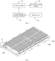
- FIG. 1 is a schematic structural diagram of a battery pack according to an example embodiment.
- the battery pack includes a control module 101, a battery core 102, a liquid leakage detection module 103, and a pre-charge switch module 104.
- the liquid leakage detection module is connected with the control module, and the liquid leakage detection module is configured to send a liquid leakage signal to the control module when detecting that liquid leakage occurs in the battery core.
- the liquid leakage detection module 103 is configured to detect a liquid leakage status of the battery core 102 to obtain a liquid leakage signal that can characterize liquid leakage in the battery core 102, and send the liquid leakage signal to the control module 101.
- FIG. 2 is a schematic structural diagram of hardware of a battery pack according to an example embodiment.
- a tray 201 may be arranged at the bottom of the battery pack, and a plurality of battery cores 102 are arranged on the tray.
- the plurality of battery cores 102 may be connected in series in sequence to form a power supply section of the battery pack.
- the number of battery cores in the battery pack may be set according to actual requirements, and is not limited in this embodiment.
- the liquid leakage detection module includes a liquid leakage detection strip
- the liquid leakage detection strip includes a signal output wire and a signal input wire; one end of the signal output wire is connected with the control module, and another end of the signal output wire is unconnected; one end of the signal input wire is connected with the control module, and another end of the signal input wire is unconnected;
- the liquid leakage detection module 103 may include a liquid leakage detection strip, and the liquid leakage detection strip is disposed at a preset position in the battery pack to detect the liquid leakage status of the battery core.
- FIG. 3 is a partially enlarged schematic view of part A in FIG. 2 , the liquid leakage detection strip includes a signal output wire 1031 and a signal input wire 1032. One end of the signal output wire is connected with a signal output end of the control module, and another end of the signal output wire is unconnected. One end of the signal input wire is connected with a signal input end of the control module 101, and another end of the signal input wire is unconnected.
- the signal output wire includes an insulating layer and a metal wire located in the insulating layer.
- the signal input wire also includes an insulating layer and a metal wire located in the insulating layer.
- the insulating layer of the signal output wire and the insulating layer of the signal input wire are each provided with a plurality of holes 1033 arranged at intervals.
- the signal output end of the control module 101 may output a detection signal, such as a pulse signal of a preset frequency. If a liquid leaked from the battery core soaks the liquid leakage detection strip, the liquid may enter the insulating layers through the holes on the insulating layers and contact with the metal wire in the signal output wire 1031 and the metal wire in the signal input wire 1032. In this case, the signal output wire 1031 and the signal input wire 1032 are short-circuited by the liquid, the detection signal output from the signal output end is transmitted from the signal output wire 1031 to the signal input wire 1032, and the signal input wire 1032 transmits the detection signal to the signal input end of the control module 101 as the liquid leakage signal.
- a detection signal such as a pulse signal of a preset frequency.
- the signal output wire 1031 and the signal input wire 1032 are disconnected. Because the detection signal cannot be transmitted to the control module, the control module cannot receive the liquid leakage signal.
- the detection signal may also be a constant voltage signal. The specific type of the detection signal may be set as required.
- the liquid leakage detection module adopts the form of liquid leakage detection strip, and the liquid leakage detection module can be conveniently arranged at the preset position in the battery pack. Moreover, the detection range of the liquid leakage detection module may be increased by increasing the length of the liquid leakage detection strip.
- the liquid leakage detection strip may be arranged at a position where electrolyte solution leakage is likely to occur in the battery pack, for example, at a cooling pipe joint, a housing weld joint, or a cell anti-explosion valve in the battery pack.
- the battery pack may further include an anti-explosion valve, and the liquid leakage detection module is arranged at a detection position of the anti-explosion valve.
- the battery pack may include a cell anti-explosion valve 202.
- the liquid leakage detection strip may be disposed at the bottom of the cell anti-explosion valve, i.e. at the detection position of the anti-explosion valve.
- the liquid leakage detection strip may be tightly attached to a surface of the tray 201.
- the specific position of the detection position in the battery pack may be set as required, and is not limited in this embodiment.
- the arrangement of the liquid leakage detection module at the detection position of the cell anti-explosion valve can improve the timeliness and accuracy of liquid leakage detection.
- the battery pack may further include a housing, the battery core is located in the housing, and the detection module is arranged at a preset position in the housing.
- the battery pack may further include a housing.
- the housing is engaged with the tray 201, and devices such as the control module 101, the battery core 102, the liquid leakage detection module 103, and the pre-charge switch module 104 are all located in the sealed housing.
- the liquid leakage detection strip may be located at the preset position in the housing as shown in FIG. 2 . When the liquid leakage detection strip is located in the housing, the liquid leakage status inside the housing can be detected in time, thereby improving the timeliness and accuracy of liquid leakage detection.
- a plurality of liquid leakage detection strips may be arranged in the battery pack according to a detection requirement.
- a liquid leakage detection strip may be arranged at a cooling pipe joint in the battery pack to detect leakage of a coolant from a cooling pipe.
- a liquid leakage detection strip may also be arranged at an electrode of the battery core to detect leakage of an electrolyte solution at the electrode.
- a liquid leakage detection strip may be arranged at a weld joint between the housing and the tray to detect liquid leakage between the housing and the tray. In the arrangement of the liquid leakage detection strip, the liquid leakage detection strip may be tightly attached to the surface of the tray, and the leaked liquid can quickly immerse the liquid leakage detection strip.
- the liquid leakage detection strip may be arranged at a position where liquid deposition is likely to occur in the battery pack, and the leaked liquid can quickly connect the signal output wire and the signal input wire.
- the specific arrangement method and the arrangement position of the liquid leakage detection strip may be set as required, and is not limited in this embodiment.
- the liquid leakage detection module may include, but is not limited to, the liquid leakage detection strip as described above, and other types of liquid detection modules in the art may also be applied to this embodiment.
- the specific type of the liquid leakage detection module is not limited in this embodiment.
- the battery pack may further include a cooling system, and the liquid leakage detection module may also detect leakage of a liquid such as a coolant from the cooling system.
- one or more liquid leakage detection modules may be arranged in the battery pack. The arrangement position and the number of the liquid leakage detection modules are not limited in this embodiment.
- the control module is connected with the pre-charge switch module, and the control module is configured to prohibit sending a pre-charge on signal to the pre-charge switch module upon receiving the liquid leakage signal while receiving a start signal for starting the battery core.
- the control module 101 is configured to control charging and discharging of the battery pack.
- the control module 101 is a battery management unit (BMU) in a battery management system (BMS).
- the BMU is configured to monitor a status of the battery core in the battery pack and control the charging and discharging of the battery pack.
- FIG. 4 is a schematic structural diagram of a battery management system according to an example embodiment.
- the battery pack includes a plurality of battery cores. Each of the battery cores is equipped with a battery information collector (BIC).
- BIC battery information collector
- the BMU is respectively connected with each BIC.
- the BMU may collect information such as temperature, battery level and voltage of the battery cores through the BICs.
- the plurality of battery cores are connected in series to form a power supply section of the battery pack.
- a negative electrode of the power supply section is connected with the BMU through a high voltage sampling unit (HVSU).
- the BMU may collect voltage information of the entire power supply section through the HVSU.
- the start signal is used for starting the battery pack.
- the battery pack may provide different voltages for a vehicle at different stages during the operation of the vehicle.
- the BMU may be connected with a vehicle control unit (VCU) in the vehicle.
- VCU vehicle control unit
- the BMU may receive a start signal sent by the VCU.
- the BMU may start the battery pack, and the battery pack controls the power supply section in the battery pack (i.e., the plurality of battery cores in the battery pack) to provide a pre-charge voltage for the vehicle at a starting stage of the vehicle, and controls the power supply section to provide an operating voltage for the vehicle at an operation stage of the vehicle.
- the pre-charge voltage is used for providing a low buffer voltage to a power consuming section in the vehicle at the starting stage, and the operating voltage is used for providing a high rated voltage to the power consuming section in the vehicle at the operation stage.
- the specific process of obtaining the start signal by the control module may be set as required, and is not limited in this embodiment.
- the control module prohibits sending the pre-charge on signal to the pre-charge switch module for starting the battery core. to prohibit the power supply section from operating to provide the pre-charge voltage to the vehicle.
- the pre-charge switch module is configured to prohibit connection of the pre-charge voltage end and the power output end when not receiving the pre-charge on signal, to prohibit the battery core from outputting a pre-charge voltage through the power output end.
- the battery pack may further be provided with a safety module and a buck module.
- the safety module is, for example, a fuse.
- the buck module may include a pre-charge resistor.
- the safety module may prevent the battery pack from overvoltage and overcurrent.
- the buck module may lower an output voltage of the power supply section to obtain the pre-charge voltage.
- a high-voltage connector may further be arranged in the battery pack.
- the pre-charge switch module may be a pre-charge relay.
- a positive electrode of the power supply section is connected with an input end of the safety module, an output end of the safety module is connected with an input end of the buck module, an output of the buck module is connected with one end of the pre-charge relay, and another end of the pre-charge relay is connected with a positive electrode power supply terminal in the high-voltage connector.
- the safety module, the buck module, the pre-charge relay, and the positive electrode power supply terminal constitute a pre-charge voltage output circuit.
- the buck module lowers the output voltage of the power supply section to obtain the pre-charge voltage at the output end of the buck module, that is, the output end of the buck module is the pre-charge voltage end.
- the pre-charge voltage may be transmitted to the positive electrode power supply terminal in the high-voltage connector, and the positive electrode power supply terminal constitutes the power output end of the battery pack.
- the battery pack may further include a negative electrode relay, the negative electrode of the power supply section may be connected with one end of the negative electrode relay through the HVSU, and another end of the negative electrode relay is connected with a negative electrode power supply terminal in the high-voltage connector.
- a positive electrode of the power supply section may be connected with the positive electrode power supply terminal
- the negative electrode of the power supply section may be connected with the negative electrode power supply terminal
- the power supply section outputs the pre-charge voltage through the power supply output end (positive electrode power supply terminal), and provides the pre-charge voltage to the vehicle through the positive electrode power supply terminal and the negative electrode power supply terminal, to pre-charge the vehicle.
- the pre-charge on signal may be an on signal of the pre-charge relay.
- the pre-charge relay does not receive the pre-charge on signal sent by the BMU, the pre-charge relay is prohibited from being turned on.
- the pre-charge voltage end is disconnected from the power output end, the pre-charge voltage cannot be transmitted to the power output end, the vehicle cannot obtain the pre-charge voltage and cannot be started, and the battery core does not discharge to the outside and is in a stopped state.
- the type of the pre-charge switch module may include but is not limited to the pre-charge relay described above, and the specific configuration of the pre-charge voltage output circuit may be set as required, and is not limited in this embodiment.
- the battery pack includes a control module, a battery core, a liquid leakage detection module, and a pre-charge switch module.
- the liquid leakage detection module is connected with the control module, and the liquid leakage detection module is configured to send a liquid leakage signal to the control module when detecting that liquid leakage occurs in the battery core.
- the control module is configured to prohibit sending a pre-charge on signal to the pre-charge switch module upon receiving the liquid leakage signal while receiving a start signal for starting the battery core.
- the pre-charge switch module is configured to prohibit connection of the pre-charge voltage end and the power output end when not receiving the pre-charge on signal, to prohibit the battery core from outputting a pre-charge voltage through the power output end.
- the control module may control the battery core not to output the pre-charge voltage, to prevent the battery pack from being started in a liquid leakage state, thereby effectively protecting the battery pack.
- control module is further configured to send the pre-charge on signal to the pre-charge switch module if not receiving the liquid leakage signal while receiving the start signal; and the pre-charge switch module is further configured to connect the pre-charge voltage end and the power output end when receiving the pre-charge on signal, causing the battery core to output the pre-charge voltage.
- control module may send the pre-charge on signal to the pre-charge switch module if not receiving the liquid leakage signal after receiving the start signal.
- the BMU may determine that the BMU has not received the liquid leakage signal. In this case, the BMU may send the pre-charge on signal to the pre-charge relay, where the pre-charge on signal is the on signal of the pre-charge relay.
- the pre-charge relay may be turned on after receiving the pre-charge on signal, to connect the pre-charge voltage end and the power output end.
- the power supply section can output the pre-charge voltage through the power output end to provide the pre-charge voltage to the vehicle.
- control module may control the battery core to output the pre-charge voltage, and provide the pre-charge voltage to the vehicle at the starting stage, and the vehicle can start running in a safe state.
- the battery pack may further include an operation switch module, where one end of the operation switch module is connected with an operating voltage end of the battery core, and another end of the operation switch module is connected with the power output end;
- the operation switch module may be an operation relay
- the output end of the safety module may further be connected with one end of the operation relay
- another end of the operation relay is connected with the positive electrode power supply terminal.
- the safety module, the operation relay, and the positive electrode power supply terminal constitute an operating voltage output circuit.
- the output end of the safety module directly outputs the voltage of the power supply section, that is, the operating voltage, and the output end of the safety module is the operating voltage end.
- the BMU may send a pre-charge off signal to the pre-charge relay and the operation on signal to the operation relay.
- the pre-charge relay is disconnected after receiving the pre-charge off signal, to disconnect the pre-charge voltage end from the power output end.
- the operation relay is turned on after receiving the operation on signal, to connect the operating voltage end and the power output end, causing the power supply section to output the operating voltage and to provide the operating voltage to the vehicle.
- the BMU may prohibit sending the operation on signal to the operation relay.
- the operation relay is prohibited from being turned on before receiving the operation on signal, to avoid connecting the operating voltage end and the power output end, and prevent the battery core from outputting the operating voltage, thereby preventing the battery core from operating in a liquid leakage state.
- control module may directly receive the pre-charge completion signal sent by the VCU, or may actively detect a status of the vehicle to obtain the pre-charge completion signal.
- the method of acquiring the pre-charge completion signal may be set as required.
- the type of the operation switch module may include but is not limited to the operation relay described above, and the specific configuration of the operating voltage output circuit may be set as required, and is not limited in this embodiment.
- the control module may prohibit the operation switch module from connecting the operating voltage end and the power output end, to prohibit the battery core from outputting the operating voltage, thereby preventing the battery core from outputting the operating voltage in the liquid leakage state, and effectively protecting the battery core.
- control module is further configured to send an operation off signal to the operation switch module upon receiving the liquid leakage signal when operation stop permission is granted; and the operation switch module is further configured to disconnect the operating voltage end from the power output end when receiving the operation off signal, to prohibit the battery core from outputting the operating voltage.
- control module may stop the operation of the battery pack upon receiving the liquid leakage signal when operation stop permission is granted.
- the BMU may send an operation off signal to the operation relay when the operation stop permission is granted, and the operation relay is disconnected after receiving the operation off signal, to disconnect the operating voltage end from the power output end, to prohibit the battery core from outputting the operating voltage. In this case, the vehicle does not receive the operating voltage and stops running.
- the VCU may send an authorization instruction to the BMU.
- the BMU After receiving the authorization instruction, the BMU has the operation stop permission.
- the BMU may send the operation off signal to the operation relay.
- the BMU does not have the operation stop permission before receiving the authorization instruction. In this case, the BMU does not send the operation off signal when receiving the liquid leakage signal.
- control module may send the operation off signal upon receiving the liquid leakage signal, to prohibit the battery core from outputting the operating voltage, thereby preventing the battery core from continuing to operate in the liquid leakage state, and effectively protecting the battery core.
- the battery pack may further include a power supply module, where the power supply module is connected with the control module and is configured to provide an independent power supply for the control module.
- step 501 a start signal for starting the battery core is received.
- the method for controlling a battery pack may be executed by the control module shown in FIG. 1 .
- the control module shown in FIG. 1 For a specific implementation process of the method for controlling a battery pack, reference may be made to the above-mentioned embodiment, and details are not repeated in this embodiment.
- the battery pack includes a control module, a battery core, a liquid leakage detection module, and a pre-charge switch module.
- the liquid leakage detection module is connected with the control module, and the liquid leakage detection module is configured to send a liquid leakage signal to the control module when detecting that liquid leakage occurs in the battery core.
- the control module is configured to prohibit sending a pre-charge on signal to the pre-charge switch module upon receiving the liquid leakage signal while receiving a start signal for starting the battery core.
- the pre-charge switch module is configured to prohibit connection of the pre-charge voltage end and the power output end when not receiving the pre-charge on signal, to prohibit the battery core from outputting a pre-charge voltage through the power output end.
- the control module may control the battery core not to output the pre-charge voltage, to prevent the battery pack from being started in a liquid leakage state, thereby effectively protecting the battery pack.
- An embodiment of the present disclosure also provides a readable storage medium.
- the readable storage medium stores a program or instructions. When executed by a processor, the program or instructions implement the processes in the method for controlling a battery pack, to achieve the same technical effect as that achieved by the method. In order to avoid repetition, details are not repeated in here.
Landscapes
- Engineering & Computer Science (AREA)
- Chemical & Material Sciences (AREA)
- Chemical Kinetics & Catalysis (AREA)
- Electrochemistry (AREA)
- General Chemical & Material Sciences (AREA)
- Manufacturing & Machinery (AREA)
- Power Engineering (AREA)
- Sustainable Energy (AREA)
- Life Sciences & Earth Sciences (AREA)
- Sustainable Development (AREA)
- Transportation (AREA)
- Mechanical Engineering (AREA)
- General Physics & Mathematics (AREA)
- Physics & Mathematics (AREA)
- Aviation & Aerospace Engineering (AREA)
- Microelectronics & Electronic Packaging (AREA)
- Charge And Discharge Circuits For Batteries Or The Like (AREA)
- Battery Mounting, Suspending (AREA)
- Secondary Cells (AREA)
- Protection Of Static Devices (AREA)
Abstract
Description
- The present disclosure claims priority to and benefits of
Chinese Patent Application No. 202011541853.8, filed on December 23, 2020 - The present disclosure belongs to the field of electronic technologies, and specifically to a battery pack, a method for controlling a battery pack, and a vehicle.
- With the development of battery technologies, new energy vehicles have entered people's daily life and become one of the main means of transportation. Battery pack is the power source of new energy vehicles, and the running status of the battery pack determines whether new energy vehicles can run safely and stably.
- A battery pack includes a battery core. When a fault occurs, the electrolyte overflows from the battery core, affecting the safe operation of the battery pack. In order to prevent the battery pack from running in a liquid leakage state, a liquid leakage detection device is usually arranged outside the battery pack. When detecting that liquid leakage occurs in the battery pack, the liquid leakage detection device sends out a liquid leakage alarm signal to remind the user to turn off the running battery pack, so as to prevent the battery pack from running in the liquid leakage state and affect the safety of new energy vehicles.
- In the related art, the liquid leakage detection device can only detect the liquid leakage status and cannot control the battery pack when liquid leakage occurs. As a result, the battery pack continues to operate in the liquid leakage state.
- An objective of embodiments of the present disclosure is to provide a battery pack, a method for controlling a battery pack, and a vehicle, which can solve the problem that the liquid leakage detection device in the related art can only detect the liquid leakage status and cannot control the battery pack when liquid leakage occurs.
- To solve the above-mentioned technical problems, the present disclosure is implemented as follows:
According to a first aspect, an embodiment of the present disclosure provides a battery pack, including: a control module, a battery core, a liquid leakage detection module, and a pre-charge switch module, - the liquid leakage detection module is connected with the control module, and the liquid leakage detection module is configured to send a liquid leakage signal to the control module when detecting that liquid leakage occurs in the battery core;
- the control module is connected with the pre-charge switch module, and the control module is configured to prohibit sending a pre-charge on signal to the pre-charge switch module upon receiving the liquid leakage signal while receiving a start signal for starting the battery core;
- one end of the pre-charge switch module is connected with a pre-charge voltage end of the battery core, and another end of the pre-charge switch module is connected with a power output end of the battery pack; and the pre-charge switch module is configured to prohibit connection of the pre-charge voltage end and the power output end when not receiving the pre-charge on signal, to prohibit the battery core from outputting a pre-charge voltage through the power output end.
- According to a second aspect, an embodiment of the present disclosure provides a method for controlling a battery pack, and the battery pack includes a control module, a battery core, a liquid leakage detection module, and a pre-charge switch module, the liquid leakage detection module is connected with the control module, the control module is connected with the pre-charge switch module, one end of the pre-charge switch module is connected with a pre-charge voltage end of the battery core, and another end of the pre-charge switch module is connected with a power output end of the battery pack; and the method is applied to the control module and includes:
- receiving a start signal for starting the battery core; and
- if a liquid leakage signal of the battery core sent by the liquid leakage detection module is received, prohibiting sending a pre-charge on signal to the pre-charge switch module, and when not receiving the pre-charge on signal, the pre-charge switch module prohibits connection of the pre-charge voltage end of the battery core and the power output end of the battery pack, to prohibit the battery core from outputting a pre-charge voltage through the power output end.
- In an embodiment of the present disclosure, the battery pack includes a control module, a battery core, a liquid leakage detection module, and a pre-charge switch module. The liquid leakage detection module is connected with the control module, and the liquid leakage detection module is configured to send a liquid leakage signal to the control module when detecting that liquid leakage occurs in the battery core. The control module is configured to prohibit sending a pre-charge on signal to the pre-charge switch module upon receiving the liquid leakage signal while receiving a start signal for starting the battery core. The pre-charge switch module is configured to prohibit connection of the pre-charge voltage end and the power output end when not receiving the pre-charge on signal, to prohibit the battery core from outputting a pre-charge voltage through the power output end. In a power-on start-up stage, if receiving the liquid leakage signal, the control module may control the battery core not to output the pre-charge voltage, to prevent the battery pack from being started in a liquid leakage state, thereby effectively protecting the battery pack.
-
-
FIG. 1 is a schematic structural diagram of a battery pack according to an example embodiment; -
FIG. 2 is a schematic structural diagram of hardware of a battery pack according to an example embodiment; -
FIG. 3 is a partially enlarged schematic view of part A inFIG. 2 ; -
FIG. 4 is a schematic structural diagram of a battery management system according to an example embodiment; and -
FIG. 5 is a flowchart of steps of a method for controlling a battery pack according to an example embodiment. - The technical solutions in the embodiments of the present disclosure are clearly and completely described in the following with reference to the accompanying drawings in the embodiments of the present disclosure. Apparently, the described embodiments are merely some rather than all of the embodiments of the present disclosure. All other embodiments obtained by a person of ordinary skill in the art based on the embodiments of the present disclosure without creative efforts shall fall within the protection scope of the present disclosure.
- In the specification and claims of the present disclosure, the terms "first", "second" or the like are intended to distinguish between similar objects but do not indicate a particular order or sequence. It is to be understood that the data termed in such a way are interchangeable in appropriate circumstances, and the embodiments of the present disclosure can be implemented in orders other than the order illustrated or described herein. In addition, "and/or" in the specification and claims indicates at least one of the associated objects. The character "/" generally indicates an "or" relation between the associated objects.
- The battery pack provided in an embodiment of the present disclosure will be described in detail with reference to the accompanying drawings through specific embodiments and application scenarios.
-
FIG. 1 is a schematic structural diagram of a battery pack according to an example embodiment. As shown inFIG. 1 , the battery pack includes acontrol module 101, abattery core 102, a liquidleakage detection module 103, and apre-charge switch module 104. - The liquid leakage detection module is connected with the control module, and the liquid leakage detection module is configured to send a liquid leakage signal to the control module when detecting that liquid leakage occurs in the battery core.
- In this embodiment, the liquid
leakage detection module 103 is configured to detect a liquid leakage status of thebattery core 102 to obtain a liquid leakage signal that can characterize liquid leakage in thebattery core 102, and send the liquid leakage signal to thecontrol module 101.FIG. 2 is a schematic structural diagram of hardware of a battery pack according to an example embodiment. Atray 201 may be arranged at the bottom of the battery pack, and a plurality ofbattery cores 102 are arranged on the tray. The plurality ofbattery cores 102 may be connected in series in sequence to form a power supply section of the battery pack. The number of battery cores in the battery pack may be set according to actual requirements, and is not limited in this embodiment. - Optionally, the liquid leakage detection module includes a liquid leakage detection strip, and the liquid leakage detection strip includes a signal output wire and a signal input wire; one end of the signal output wire is connected with the control module, and another end of the signal output wire is unconnected; one end of the signal input wire is connected with the control module, and another end of the signal input wire is unconnected;
- the signal output wire is configured to connect to the signal input wire when liquid leakage occurs in the battery core, to transmit a detection signal sent by the control module to the signal input wire; the signal input wire is configured to transmit the detection signal as the liquid leakage signal to the control module when receiving the detection signal; and
- the signal output wire is further configured to disconnect from the signal input wire when no liquid leakage occurs in the battery core, to prohibit the signal input wire from transmitting the detection signal to the control module as the liquid leakage signal.
- In an embodiment, the liquid
leakage detection module 103 may include a liquid leakage detection strip, and the liquid leakage detection strip is disposed at a preset position in the battery pack to detect the liquid leakage status of the battery core.FIG. 3 is a partially enlarged schematic view of part A inFIG. 2 , the liquid leakage detection strip includes asignal output wire 1031 and asignal input wire 1032. One end of the signal output wire is connected with a signal output end of the control module, and another end of the signal output wire is unconnected. One end of the signal input wire is connected with a signal input end of thecontrol module 101, and another end of the signal input wire is unconnected. The signal output wire includes an insulating layer and a metal wire located in the insulating layer. The signal input wire also includes an insulating layer and a metal wire located in the insulating layer. The insulating layer of the signal output wire and the insulating layer of the signal input wire are each provided with a plurality ofholes 1033 arranged at intervals. - In the operation of the liquid leakage detection strip, the signal output end of the
control module 101 may output a detection signal, such as a pulse signal of a preset frequency. If a liquid leaked from the battery core soaks the liquid leakage detection strip, the liquid may enter the insulating layers through the holes on the insulating layers and contact with the metal wire in thesignal output wire 1031 and the metal wire in thesignal input wire 1032. In this case, thesignal output wire 1031 and thesignal input wire 1032 are short-circuited by the liquid, the detection signal output from the signal output end is transmitted from thesignal output wire 1031 to thesignal input wire 1032, and thesignal input wire 1032 transmits the detection signal to the signal input end of thecontrol module 101 as the liquid leakage signal. On the contrary, when no liquid leakage occurs in the battery core, thesignal output wire 1031 and thesignal input wire 1032 are disconnected. Because the detection signal cannot be transmitted to the control module, the control module cannot receive the liquid leakage signal. The detection signal may also be a constant voltage signal. The specific type of the detection signal may be set as required. - In practical applications, the liquid leakage detection module adopts the form of liquid leakage detection strip, and the liquid leakage detection module can be conveniently arranged at the preset position in the battery pack. Moreover, the detection range of the liquid leakage detection module may be increased by increasing the length of the liquid leakage detection strip.
- In an embodiment, the liquid leakage detection strip may be arranged at a position where electrolyte solution leakage is likely to occur in the battery pack, for example, at a cooling pipe joint, a housing weld joint, or a cell anti-explosion valve in the battery pack.
- Optionally, the battery pack may further include an anti-explosion valve, and the liquid leakage detection module is arranged at a detection position of the anti-explosion valve.
- As shown in
FIG. 3 , the battery pack may include acell anti-explosion valve 202. The liquid leakage detection strip may be disposed at the bottom of the cell anti-explosion valve, i.e. at the detection position of the anti-explosion valve. The liquid leakage detection strip may be tightly attached to a surface of thetray 201. The specific position of the detection position in the battery pack may be set as required, and is not limited in this embodiment. - In practical applications, because of the high risk of electrolyte solution leakage at the anti-explosion valve, the arrangement of the liquid leakage detection module at the detection position of the cell anti-explosion valve can improve the timeliness and accuracy of liquid leakage detection.
- Optionally, the battery pack may further include a housing, the battery core is located in the housing, and the detection module is arranged at a preset position in the housing.
- As shown in
FIG. 2 , the battery pack may further include a housing. The housing is engaged with thetray 201, and devices such as thecontrol module 101, thebattery core 102, the liquidleakage detection module 103, and thepre-charge switch module 104 are all located in the sealed housing. The liquid leakage detection strip may be located at the preset position in the housing as shown inFIG. 2 . When the liquid leakage detection strip is located in the housing, the liquid leakage status inside the housing can be detected in time, thereby improving the timeliness and accuracy of liquid leakage detection. - In an embodiment, a plurality of liquid leakage detection strips may be arranged in the battery pack according to a detection requirement. Based on the above example, a liquid leakage detection strip may be arranged at a cooling pipe joint in the battery pack to detect leakage of a coolant from a cooling pipe. In addition, a liquid leakage detection strip may also be arranged at an electrode of the battery core to detect leakage of an electrolyte solution at the electrode. Alternatively, a liquid leakage detection strip may be arranged at a weld joint between the housing and the tray to detect liquid leakage between the housing and the tray. In the arrangement of the liquid leakage detection strip, the liquid leakage detection strip may be tightly attached to the surface of the tray, and the leaked liquid can quickly immerse the liquid leakage detection strip. Alternatively, the liquid leakage detection strip may be arranged at a position where liquid deposition is likely to occur in the battery pack, and the leaked liquid can quickly connect the signal output wire and the signal input wire. The specific arrangement method and the arrangement position of the liquid leakage detection strip may be set as required, and is not limited in this embodiment.
- It should be noted that the liquid leakage detection module may include, but is not limited to, the liquid leakage detection strip as described above, and other types of liquid detection modules in the art may also be applied to this embodiment. The specific type of the liquid leakage detection module is not limited in this embodiment. The battery pack may further include a cooling system, and the liquid leakage detection module may also detect leakage of a liquid such as a coolant from the cooling system. In addition, for the liquid leakage detection module, according to characteristics of the battery pack, one or more liquid leakage detection modules may be arranged in the battery pack. The arrangement position and the number of the liquid leakage detection modules are not limited in this embodiment.
- The control module is connected with the pre-charge switch module, and the control module is configured to prohibit sending a pre-charge on signal to the pre-charge switch module upon receiving the liquid leakage signal while receiving a start signal for starting the battery core.
- In this embodiment, the
control module 101 is configured to control charging and discharging of the battery pack. For example, thecontrol module 101 is a battery management unit (BMU) in a battery management system (BMS). The BMU is configured to monitor a status of the battery core in the battery pack and control the charging and discharging of the battery pack.FIG. 4 is a schematic structural diagram of a battery management system according to an example embodiment. The battery pack includes a plurality of battery cores. Each of the battery cores is equipped with a battery information collector (BIC). The BMU is respectively connected with each BIC. The BMU may collect information such as temperature, battery level and voltage of the battery cores through the BICs. The plurality of battery cores are connected in series to form a power supply section of the battery pack. A negative electrode of the power supply section is connected with the BMU through a high voltage sampling unit (HVSU). The BMU may collect voltage information of the entire power supply section through the HVSU. - The start signal is used for starting the battery pack. After being started, the battery pack may provide different voltages for a vehicle at different stages during the operation of the vehicle. For example, the BMU may be connected with a vehicle control unit (VCU) in the vehicle. The BMU may receive a start signal sent by the VCU. After receiving the start signal, the BMU may start the battery pack, and the battery pack controls the power supply section in the battery pack (i.e., the plurality of battery cores in the battery pack) to provide a pre-charge voltage for the vehicle at a starting stage of the vehicle, and controls the power supply section to provide an operating voltage for the vehicle at an operation stage of the vehicle. The pre-charge voltage is used for providing a low buffer voltage to a power consuming section in the vehicle at the starting stage, and the operating voltage is used for providing a high rated voltage to the power consuming section in the vehicle at the operation stage. The specific process of obtaining the start signal by the control module may be set as required, and is not limited in this embodiment.
- In this embodiment, if receiving the liquid leakage signal while receiving the start signal, the control module prohibits sending the pre-charge on signal to the pre-charge switch module for starting the battery core. to prohibit the power supply section from operating to provide the pre-charge voltage to the vehicle.
- One end of the pre-charge switch module is connected with a pre-charge voltage end of the battery core, and another end of the pre-charge switch module is connected with a power output end of the battery pack. The pre-charge switch module is configured to prohibit connection of the pre-charge voltage end and the power output end when not receiving the pre-charge on signal, to prohibit the battery core from outputting a pre-charge voltage through the power output end.
- For example, as shown in
FIG. 4 , the battery pack may further be provided with a safety module and a buck module. The safety module is, for example, a fuse. The buck module may include a pre-charge resistor. The safety module may prevent the battery pack from overvoltage and overcurrent. The buck module may lower an output voltage of the power supply section to obtain the pre-charge voltage. A high-voltage connector may further be arranged in the battery pack. The pre-charge switch module may be a pre-charge relay. After the plurality of battery cores are connected in series to form the power supply section, a positive electrode of the power supply section is connected with an input end of the safety module, an output end of the safety module is connected with an input end of the buck module, an output of the buck module is connected with one end of the pre-charge relay, and another end of the pre-charge relay is connected with a positive electrode power supply terminal in the high-voltage connector. The safety module, the buck module, the pre-charge relay, and the positive electrode power supply terminal constitute a pre-charge voltage output circuit. During the operation of the power supply section, the buck module lowers the output voltage of the power supply section to obtain the pre-charge voltage at the output end of the buck module, that is, the output end of the buck module is the pre-charge voltage end. After the pre-charge relay is turned on, the pre-charge voltage may be transmitted to the positive electrode power supply terminal in the high-voltage connector, and the positive electrode power supply terminal constitutes the power output end of the battery pack. - In addition, the battery pack may further include a negative electrode relay, the negative electrode of the power supply section may be connected with one end of the negative electrode relay through the HVSU, and another end of the negative electrode relay is connected with a negative electrode power supply terminal in the high-voltage connector. After the negative electrode relay and the pre-charge relay are turned on, a positive electrode of the power supply section may be connected with the positive electrode power supply terminal, and the negative electrode of the power supply section may be connected with the negative electrode power supply terminal, and the power supply section outputs the pre-charge voltage through the power supply output end (positive electrode power supply terminal), and provides the pre-charge voltage to the vehicle through the positive electrode power supply terminal and the negative electrode power supply terminal, to pre-charge the vehicle.
- Based on the above example, the pre-charge on signal may be an on signal of the pre-charge relay. When the pre-charge relay does not receive the pre-charge on signal sent by the BMU, the pre-charge relay is prohibited from being turned on. In this case, the pre-charge voltage end is disconnected from the power output end, the pre-charge voltage cannot be transmitted to the power output end, the vehicle cannot obtain the pre-charge voltage and cannot be started, and the battery core does not discharge to the outside and is in a stopped state.
- It should be noted that the type of the pre-charge switch module may include but is not limited to the pre-charge relay described above, and the specific configuration of the pre-charge voltage output circuit may be set as required, and is not limited in this embodiment.
- To sum up, in this embodiment, the battery pack includes a control module, a battery core, a liquid leakage detection module, and a pre-charge switch module. The liquid leakage detection module is connected with the control module, and the liquid leakage detection module is configured to send a liquid leakage signal to the control module when detecting that liquid leakage occurs in the battery core. The control module is configured to prohibit sending a pre-charge on signal to the pre-charge switch module upon receiving the liquid leakage signal while receiving a start signal for starting the battery core. The pre-charge switch module is configured to prohibit connection of the pre-charge voltage end and the power output end when not receiving the pre-charge on signal, to prohibit the battery core from outputting a pre-charge voltage through the power output end. In a power-on start-up stage, if receiving the liquid leakage signal, the control module may control the battery core not to output the pre-charge voltage, to prevent the battery pack from being started in a liquid leakage state, thereby effectively protecting the battery pack.
- Optionally, the control module is further configured to send the pre-charge on signal to the pre-charge switch module if not receiving the liquid leakage signal while receiving the start signal; and
the pre-charge switch module is further configured to connect the pre-charge voltage end and the power output end when receiving the pre-charge on signal, causing the battery core to output the pre-charge voltage. - In an embodiment, the control module may send the pre-charge on signal to the pre-charge switch module if not receiving the liquid leakage signal after receiving the start signal. Based on the above example, if not receiving the detection signal from the liquid leakage detection strip after receiving the start signal sent by the VCU, the BMU may determine that the BMU has not received the liquid leakage signal. In this case, the BMU may send the pre-charge on signal to the pre-charge relay, where the pre-charge on signal is the on signal of the pre-charge relay.
- Correspondingly, the pre-charge relay may be turned on after receiving the pre-charge on signal, to connect the pre-charge voltage end and the power output end. In this case, the power supply section can output the pre-charge voltage through the power output end to provide the pre-charge voltage to the vehicle.
- In practical applications, if not receiving the liquid leakage signal after receiving the start signal, the control module may control the battery core to output the pre-charge voltage, and provide the pre-charge voltage to the vehicle at the starting stage, and the vehicle can start running in a safe state.
- Optionally, the battery pack may further include an operation switch module, where one end of the operation switch module is connected with an operating voltage end of the battery core, and another end of the operation switch module is connected with the power output end;
- the control module is further configured to prohibit sending an operation on signal to the operation switch module upon receiving the liquid leakage signal while receiving a pre-charge completion signal, where the pre-charge completion signal is used for causing the battery core to stop outputting the pre-charge voltage and output the operating voltage; and
- the operation switch module is configured to prohibit connection of the operating voltage end and the power output end when not receiving the operation on signal, to prohibit the battery core from outputting the operating voltage through the power output end.
- For example, as shown in
FIG. 4 , the operation switch module may be an operation relay, the output end of the safety module may further be connected with one end of the operation relay, and another end of the operation relay is connected with the positive electrode power supply terminal. The safety module, the operation relay, and the positive electrode power supply terminal constitute an operating voltage output circuit. The output end of the safety module directly outputs the voltage of the power supply section, that is, the operating voltage, and the output end of the safety module is the operating voltage end. After pre-charging of the vehicle at the starting stage is completed, the vehicle may switch from the starting stage to the operation stage. In this case, the VCU may send the pre-charge completion signal to the BMU. After receiving the pre-charge completion signal, the BMU may send a pre-charge off signal to the pre-charge relay and the operation on signal to the operation relay. Correspondingly, the pre-charge relay is disconnected after receiving the pre-charge off signal, to disconnect the pre-charge voltage end from the power output end. In addition, the operation relay is turned on after receiving the operation on signal, to connect the operating voltage end and the power output end, causing the power supply section to output the operating voltage and to provide the operating voltage to the vehicle. - If receiving the liquid leakage signal after receiving the pre-charge completion signal sent by the VCU, the BMU may prohibit sending the operation on signal to the operation relay. Correspondingly, the operation relay is prohibited from being turned on before receiving the operation on signal, to avoid connecting the operating voltage end and the power output end, and prevent the battery core from outputting the operating voltage, thereby preventing the battery core from operating in a liquid leakage state.
- It should be noted that the control module may directly receive the pre-charge completion signal sent by the VCU, or may actively detect a status of the vehicle to obtain the pre-charge completion signal. The method of acquiring the pre-charge completion signal may be set as required. The type of the operation switch module may include but is not limited to the operation relay described above, and the specific configuration of the operating voltage output circuit may be set as required, and is not limited in this embodiment.
- In practical applications, after receiving the pre-charge completion signal, the control module may prohibit the operation switch module from connecting the operating voltage end and the power output end, to prohibit the battery core from outputting the operating voltage, thereby preventing the battery core from outputting the operating voltage in the liquid leakage state, and effectively protecting the battery core.
- Optionally, the control module is further configured to send an operation off signal to the operation switch module upon receiving the liquid leakage signal when operation stop permission is granted; and
the operation switch module is further configured to disconnect the operating voltage end from the power output end when receiving the operation off signal, to prohibit the battery core from outputting the operating voltage. - In this embodiment, the control module may stop the operation of the battery pack upon receiving the liquid leakage signal when operation stop permission is granted. Based on the above example, the BMU may send an operation off signal to the operation relay when the operation stop permission is granted, and the operation relay is disconnected after receiving the operation off signal, to disconnect the operating voltage end from the power output end, to prohibit the battery core from outputting the operating voltage. In this case, the vehicle does not receive the operating voltage and stops running.
- In an embodiment, when determining that the vehicle is in a starting state and the vehicle is not in a traveling state, the VCU may send an authorization instruction to the BMU. After receiving the authorization instruction, the BMU has the operation stop permission. In this case, when receiving the liquid leakage signal, the BMU may send the operation off signal to the operation relay. On the contrary, the BMU does not have the operation stop permission before receiving the authorization instruction. In this case, the BMU does not send the operation off signal when receiving the liquid leakage signal.
- In practical applications, when the control module has the operation stop permission, the control module may send the operation off signal upon receiving the liquid leakage signal, to prohibit the battery core from outputting the operating voltage, thereby preventing the battery core from continuing to operate in the liquid leakage state, and effectively protecting the battery core.
- Optionally, the battery pack may further include a power supply module, where the power supply module is connected with the control module and is configured to provide an independent power supply for the control module.
- In this embodiment, the control module may be powered by the independent power supply to prevent the control module from stopping operating when the battery pack fails. For example, as shown in
FIG. 4 , a low-voltage connector may further be arranged in the battery pack. The power supply module may be a 12-volt storage battery or a 12-volt low-voltage power supply system. The power input end of BMU may be connected with a power output end of the storage battery through the low-voltage connector to provide an external independent power supply for the BMU. The specific type of the power module may be set as required, and is not limited in this embodiment. - In practical applications, because the power supply module provides an independent power supply for the control module, the control module can still detect the liquid leakage status when the battery pack fails, thereby effectively protecting the battery pack.
- In an embodiment, after receiving the liquid leakage signal, the control module may output an alarm signal. For example, an alarm module (such as a speaker) may be arranged in the battery pack. After receiving the liquid leakage signal, the control module may control the speaker to output an audible alarm signal to remind the user of liquid leakage.
-
FIG. 5 is a flowchart of steps of a method for controlling a battery pack according to an example embodiment. The battery pack includes a control module, a battery core, a liquid leakage detection module, and a pre-charge switch module. The liquid leakage detection module is connected with the control module. The control module is connected with the pre-charge switch module. One end of the pre-charge switch module is connected with a pre-charge voltage end of the battery core, and another end of the pre-charge switch module is connected with a power output end of the battery pack. As shown inFIG. 5 , the method may be applied to the control module and may include the following steps. - In
step 501, a start signal for starting the battery core is received. - In
step 502, if a liquid leakage signal of the battery core sent by the liquid leakage detection module is received, sending a pre-charge on signal to the pre-charge switch module is prohibited. - The pre-charge on signal is used for causing the pre-charge switch module to prohibit connection of the pre-charge voltage end of the battery core and the power output end of the battery pack when not receiving the pre-charge on signal, to prohibit the battery core from outputting a pre-charge voltage through the power output end.
- Optionally, the method may further include:
sending the pre-charge on signal to the pre-charge switch module if not receiving the liquid leakage signal. - The pre-charge on signal is used for connecting the pre-charge switch module to the pre-charge voltage end and the power output end, causing the battery core to output the pre-charge voltage.
- Optionally, the battery pack further includes an operation switch module, where one end of the operation switch module is connected with an operating voltage end of the battery core, and another end of the operation switch module is connected with the power output end; and the method may further include:
prohibiting sending an operation on signal to the operation switch module upon receiving the liquid leakage signal while receiving a pre-charge completion signal, and the operation switch module prohibits connection of the operating voltage end of the battery core and the power output end when not receiving the operation on signal, to prohibit the battery core from outputting the operating voltage through the power output end, where the pre-charge completion signal is used for causing the battery core to stop outputting the pre-charge voltage and output the operating voltage. - Optionally, the method may further include:
sending an operation off signal to the operation switch module upon receiving the liquid leakage signal when operation stop permission is granted, where the operation off signal is used for causing the operation switch module to disconnect the operating voltage end from the power output end, to prohibit the battery core from outputting the operating voltage. - In this embodiment, the method for controlling a battery pack may be executed by the control module shown in
FIG. 1 . For a specific implementation process of the method for controlling a battery pack, reference may be made to the above-mentioned embodiment, and details are not repeated in this embodiment. - To sum up, in this embodiment, the battery pack includes a control module, a battery core, a liquid leakage detection module, and a pre-charge switch module. The liquid leakage detection module is connected with the control module, and the liquid leakage detection module is configured to send a liquid leakage signal to the control module when detecting that liquid leakage occurs in the battery core. The control module is configured to prohibit sending a pre-charge on signal to the pre-charge switch module upon receiving the liquid leakage signal while receiving a start signal for starting the battery core. The pre-charge switch module is configured to prohibit connection of the pre-charge voltage end and the power output end when not receiving the pre-charge on signal, to prohibit the battery core from outputting a pre-charge voltage through the power output end. In a power-on start-up stage, upon receiving the liquid leakage signal, the control module may control the battery core not to output the pre-charge voltage, to prevent the battery pack from being started in a liquid leakage state, thereby effectively protecting the battery pack.
- An embodiment of the present disclosure also provides a readable storage medium. The readable storage medium stores a program or instructions. When executed by a processor, the program or instructions implement the processes in the method for controlling a battery pack, to achieve the same technical effect as that achieved by the method. In order to avoid repetition, details are not repeated in here.
- An embodiment of the present disclosure also provides a chip. The chip includes a processor and a communication interface. The communication interface is coupled with the processor. The processor is configured to run the program or instructions to implement the processes in the method for controlling a battery pack, to achieve the same technical effect as that achieved by the method. In order to avoid repetition, details are not repeated in here.
- It should be noted that in the present disclosure, the terms "comprise", "include" or any other variants are intended to encompass non-exclusive inclusion, such that a process, a method, an article or an apparatus including a series of elements not only include those elements, but also includes other elements not listed explicitly or includes intrinsic elements for the process, the method, the article, or the apparatus. Without any further limitation, an element defined by the phrase "comprising one" does not exclude existence of other same elements in the process, the method, the article, or the apparatus that includes the elements. In addition, it should be pointed out that, the scope of the methods and apparatus in the embodiments of the present disclosure is not limited to performing functions in the order shown or discussed, and may also include performing the functions in a substantially simultaneous manner or in reverse order depending on the functions involved, for example, the described method may be performed in a different order than that described, and various steps may also be added, omitted, or combined. In addition, features described with reference to some examples may be combined in other examples.
- Although the embodiments of the present disclosure have been described above in conjunction with the accompanying drawings, the present disclosure is not limited to the specific embodiments described above, and the specific embodiments described above are merely illustrative and not restrictive. Those having ordinary skill in the art can make various changes and modifications based on the teachings of the present disclosure without departing from the spirit of the present disclosure and the scope of the appended claims. Such changes and modifications also fall within the protection scope of the present disclosure.
Claims (12)
- A battery pack, comprising: a control module, a battery core, a liquid leakage detection module, and a pre-charge switch module, whereinthe liquid leakage detection module is connected with the control module, and the liquid leakage detection module is configured to send a liquid leakage signal to the control module when detecting that liquid leakage occurs in the battery core;the control module is connected with the pre-charge switch module, and the control module is configured to prohibit sending a pre-charge on signal to the pre-charge switch module upon receiving the liquid leakage signal while receiving a start signal for starting the battery core;one end of the pre-charge switch module is connected with a pre-charge voltage end of the battery core, and another end of the pre-charge switch module is connected with a power output end of the battery pack; and the pre-charge switch module is configured to prohibit connection of the pre-charge voltage end and the power output end when not receiving the pre-charge on signal, to prohibit the battery core from outputting a pre-charge voltage through the power output end.
- The battery pack according to claim 1, whereinthe control module is further configured to send the pre-charge on signal to the pre-charge switch module if not receiving the liquid leakage signal while receiving the start signal; andthe pre-charge switch module is further configured to connect the pre-charge voltage end and the power output end when receiving the pre-charge on signal, causing the battery core to output the pre-charge voltage.
- The battery pack according to any one of claims 1 to 2, further comprising an operation switch module, wherein one end of the operation switch module is connected with an operating voltage end of the battery core, and another end of the operation switch module is connected with the power output end;the control module is further configured to prohibit sending an operation on signal to the operation switch module upon receiving the liquid leakage signal while receiving a pre-charge completion signal; the pre-charge completion signal is used for causing the battery core to stop outputting the pre-charge voltage and output the operating voltage; andthe operation switch module is configured to prohibit connection of the operating voltage end and the power output end when not receiving the operation on signal, to prohibit the battery core from outputting the operating voltage through the power output end.
- The battery pack according to claim 3, whereinthe control module is further configured to send an operation off signal to the operation switch module upon receiving the liquid leakage signal when operation stop permission is granted; andthe operation switch module is further configured to disconnect the operating voltage end from the power output end when receiving the operation off signal, to prohibit the battery core from outputting the operating voltage.
- The battery pack according to claim 1, further comprising a power supply module, wherein the power supply module is connected with the control module and is configured to provide an independent power supply for the control module.
- The battery pack according to claim 1, the liquid leakage detection module comprises a liquid leakage detection strip, wherein the liquid leakage detection strip comprises a signal output wire and a signal input wire; one end of the signal output wire is connected with the control module, and another end of the signal output wire is unconnected; one end of the signal input wire is connected with the control module, and another end of the signal input wire is unconnected;the signal output wire is configured to connect to the signal input wire when liquid leakage occurs in the battery core, to transmit a detection signal sent by the control module to the signal input wire; the signal input wire is configured to transmit the detection signal as the liquid leakage signal to the control module when receiving the detection signal; andthe signal output wire is further configured to disconnect from the signal input wire when no liquid leakage occurs in the battery core, to prohibit the signal input wire from transmitting the detection signal to the control module as the liquid leakage signal.
- The battery pack according to any one of claims 1 to 6, further comprising an anti-explosion valve, and the liquid leakage detection module is arranged at a detection position of the anti-explosion valve.
- A method for controlling a battery pack, wherein the battery pack comprises a control module, a battery core, a liquid leakage detection module, and a pre-charge switch module, the liquid leakage detection module is connected with the control module, the control module is connected with the pre-charge switch module, one end of the pre-charge switch module is connected with a pre-charge voltage end of the battery core, and another end of the pre-charge switch module is connected with a power output end of the battery pack; and the method is applied to the control module and comprises:receiving a start signal for starting the battery core; andif a liquid leakage signal of the battery core sent by the liquid leakage detection module is received, prohibiting sending a pre-charge on signal to the pre-charge switch module, and when not receiving the pre-charge on signal, the pre-charge switch module prohibits connection of the pre-charge voltage end of the battery core and the power output end of the battery pack, to prohibit the battery core from outputting a pre-charge voltage through the power output end.
- The control method according to claim 8, further comprising:
sending the pre-charge on signal to the pre-charge switch module if not receiving the liquid leakage signal, wherein the pre-charge on signal is used for connecting the pre-charge switch module to the pre-charge voltage end and the power output end, causing the battery core to output the pre-charge voltage. - The control method according to claim 8, wherein the battery pack further comprises an operation switch module, wherein one end of the operation switch module is connected with an operating voltage end of the battery core, and another end of the operation switch module is connected with the power output end; and the method further comprises:
prohibiting sending an operation on signal to the operation switch module upon receiving the liquid leakage signal while receiving a pre-charge completion signal, causing the operation switch module to prohibit connection of the operating voltage end of the battery core and the power output end when no receiving the operation on signal, to prohibit the battery core from outputting the operating voltage through the power output end, wherein the pre-charge completion signal is used for causing the battery core to stop outputting the pre-charge voltage and output the operating voltage. - The control method according to claim 10, further comprising:
sending an operation off signal to the operation switch module upon receiving the liquid leakage signal when operation stop permission is granted, wherein the operation off signal is used for causing the operation switch module to disconnect the operating voltage end from the power output end, to prohibit the battery core from outputting the operating voltage. - A vehicle, comprising the battery pack according to any one of claims 1-7.
Applications Claiming Priority (2)
| Application Number | Priority Date | Filing Date | Title |
|---|---|---|---|
| CN202011541853.8A CN114665168B (en) | 2020-12-23 | 2020-12-23 | Battery pack, battery pack control method and vehicle |
| PCT/CN2021/092423 WO2022134429A1 (en) | 2020-12-23 | 2021-05-08 | Battery pack, control method for battery pack, and vehicle |
Publications (2)
| Publication Number | Publication Date |
|---|---|
| EP4228052A1 true EP4228052A1 (en) | 2023-08-16 |
| EP4228052A4 EP4228052A4 (en) | 2024-10-30 |
Family
ID=82025590
Family Applications (1)
| Application Number | Title | Priority Date | Filing Date |
|---|---|---|---|
| EP21908440.7A Pending EP4228052A4 (en) | 2020-12-23 | 2021-05-08 | BATTERY PACK, CONTROL METHOD FOR BATTERY PACK AND VEHICLE |
Country Status (7)
| Country | Link |
|---|---|
| US (1) | US12155044B2 (en) |
| EP (1) | EP4228052A4 (en) |
| JP (1) | JP7764477B2 (en) |
| KR (1) | KR102946753B1 (en) |
| CN (1) | CN114665168B (en) |
| CA (1) | CA3200075A1 (en) |
| WO (1) | WO2022134429A1 (en) |
Families Citing this family (5)
| Publication number | Priority date | Publication date | Assignee | Title |
|---|---|---|---|---|
| CN218472170U (en) * | 2022-09-30 | 2023-02-10 | 比亚迪股份有限公司 | Battery tray assembly, battery pack and vehicle |
| CN115795568A (en) * | 2022-10-28 | 2023-03-14 | 苏州浪潮智能科技有限公司 | Liquid cooling server liquid leakage protection method, device, equipment and storage medium |
| CN119678340A (en) * | 2022-11-08 | 2025-03-21 | 宁德时代新能源科技股份有限公司 | Battery system, control method, control unit and storage medium |
| CN115950608B (en) * | 2023-02-22 | 2023-06-02 | 苏州浪潮智能科技有限公司 | Liquid leakage detection circuit, system, method, electronic device and storage medium |
| CN116344980B (en) * | 2023-05-29 | 2023-08-01 | 苏州精控能源科技有限公司 | Battery core leakage self-diagnosis dynamic reconstruction system, method and storage medium in battery pack |
Family Cites Families (17)
| Publication number | Priority date | Publication date | Assignee | Title |
|---|---|---|---|---|
| JP3402933B2 (en) * | 1996-06-21 | 2003-05-06 | エヌイーシートーキン栃木株式会社 | Organic electrolyte battery leak detection device |
| JP4608711B2 (en) * | 1999-09-10 | 2011-01-12 | ソニー株式会社 | Battery pack |
| JP3789696B2 (en) * | 1999-11-01 | 2006-06-28 | 三洋電機株式会社 | Battery electrolyte leak inspection apparatus and battery electrolyte leak inspection method |
| JP2002359010A (en) * | 2001-05-30 | 2002-12-13 | Gs-Melcotec Co Ltd | Liquid leakage detection method for nonaqueous electrolyte battery and nonaqueous electrolyte battery |
| US8154248B2 (en) | 2008-10-07 | 2012-04-10 | Black & Decker Inc. | Signal for pre-charge selection in lithium charging and discharge control/pre-charge function |
| CN202983627U (en) * | 2012-12-24 | 2013-06-12 | 岳阳神冈起重电磁铁有限公司 | Microcomputer automatic electromagnet distributing system with power failure magnetism keeping function |
| KR101480090B1 (en) * | 2013-07-02 | 2015-01-08 | 주식회사 이아이지 | Control device for battery management system |
| CN204188345U (en) * | 2014-10-14 | 2015-03-04 | 惠州市亿能电子有限公司 | A kind of liquid cooling detection device for liquor leakage of battery bag |
| JP2017065284A (en) * | 2015-09-28 | 2017-04-06 | トヨタ自動車株式会社 | Hybrid vehicle |
| CN106532146A (en) * | 2016-10-09 | 2017-03-22 | 浙江超威创元实业有限公司 | Electric vehicle power battery box liquid leakage detection system and detection method thereof |
| JP2019010990A (en) | 2017-06-30 | 2019-01-24 | 豊田合成株式会社 | Air bag device |
| CN107221720A (en) * | 2017-07-05 | 2017-09-29 | 浙江众泰汽车制造有限公司 | The cold cell p ack leakages protection system of liquid and the automobile using the system |
| CN107959066B (en) * | 2017-11-20 | 2020-02-21 | 北京长城华冠汽车技术开发有限公司 | Liquid leakage control system and control method for power battery box of electric automobile |
| JP2019109990A (en) * | 2017-12-15 | 2019-07-04 | 株式会社豊田自動織機 | Inspection device |
| CN208458942U (en) * | 2018-12-25 | 2019-02-01 | 常州市伟宏动力技术有限公司 | Battery leakage detection device |
| CN209447982U (en) * | 2019-05-06 | 2019-09-27 | 凤凰新能源(惠州)有限公司 | A kind of lithium battery with leakage detection function |
| CN210516923U (en) * | 2019-07-25 | 2020-05-12 | 慕东林 | Storage battery structure device with function of automatically detecting leakage fault |
-
2020
- 2020-12-23 CN CN202011541853.8A patent/CN114665168B/en active Active
-
2021
- 2021-05-08 KR KR1020237014268A patent/KR102946753B1/en active Active
- 2021-05-08 WO PCT/CN2021/092423 patent/WO2022134429A1/en not_active Ceased
- 2021-05-08 CA CA3200075A patent/CA3200075A1/en active Pending
- 2021-05-08 JP JP2023534162A patent/JP7764477B2/en active Active
- 2021-05-08 EP EP21908440.7A patent/EP4228052A4/en active Pending
-
2023
- 2023-05-02 US US18/310,782 patent/US12155044B2/en active Active
Also Published As
| Publication number | Publication date |
|---|---|
| KR20230079402A (en) | 2023-06-07 |
| US12155044B2 (en) | 2024-11-26 |
| CN114665168B (en) | 2024-11-15 |
| EP4228052A4 (en) | 2024-10-30 |
| JP2023552418A (en) | 2023-12-15 |
| US20230268560A1 (en) | 2023-08-24 |
| WO2022134429A1 (en) | 2022-06-30 |
| CA3200075A1 (en) | 2022-06-30 |
| KR102946753B1 (en) | 2026-04-02 |
| CN114665168A (en) | 2022-06-24 |
| JP7764477B2 (en) | 2025-11-05 |
Similar Documents
| Publication | Publication Date | Title |
|---|---|---|
| US12155044B2 (en) | Battery pack, method for controlling a battery pack, and vehicle | |
| US10985575B2 (en) | Thermal runaway detection circuit and method | |
| EP3393001B1 (en) | Apparatus for managing secondary battery | |
| CN103026544B (en) | Safety component by fuse at high voltage battery sensing line | |
| US20140002026A1 (en) | Battery control apparatus and method | |
| KR102734327B1 (en) | Battery system for vehicle and controlling method thereof | |
| US12230987B2 (en) | Power conversion device | |
| CN112277730A (en) | Charging protection method and device for electric automobile, electric automobile and storage medium | |
| US10629964B2 (en) | Method for operating an energy storage unit, battery management system for performing such a method and energy storage unit with such a battery management system | |
| CN116345622B (en) | Switch tube protection method, battery pack and energy storage system | |
| CN112693357A (en) | Power supply and discharge method and device for power battery of new energy automobile | |
| KR102160646B1 (en) | The crack detecting method for protection circuit module type of Li ion battery | |
| CN117595442A (en) | Measurement and control module for intelligent charging and discharging and charging and discharging system using the module | |
| CN118507923A (en) | Energy storage battery module heating control and protection system and method | |
| CN107230809B (en) | Battery pack charging protection method, corresponding battery pack and battery pack charging equipment | |
| CN114665546A (en) | Grouping charging and discharging management and control equipment and method for standby lead-acid battery pack in base station room | |
| CN221150999U (en) | Measurement and control module for intelligent charge and discharge and charge and discharge system adopting module | |
| US20220094178A1 (en) | Battery pack and electric device system | |
| CN114156960A (en) | Battery pack detection method and device and power management system | |
| CN220156217U (en) | A battery core power supply protection circuit, battery pack and electric vehicle | |
| US20250210726A1 (en) | Battery system, control method, control unit, and storage medium | |
| CN219678117U (en) | Double-box lithium battery PACK and protection circuit thereof | |
| KR101358765B1 (en) | Apparatus for managing secondary battery | |
| CN115733225A (en) | A lithium battery charging and discharging switch fault diagnosis system and method | |
| KR20190080323A (en) | ASS operation power bank |
Legal Events
| Date | Code | Title | Description |
|---|---|---|---|
| STAA | Information on the status of an ep patent application or granted ep patent |
Free format text: STATUS: THE INTERNATIONAL PUBLICATION HAS BEEN MADE |
|
| PUAI | Public reference made under article 153(3) epc to a published international application that has entered the european phase |
Free format text: ORIGINAL CODE: 0009012 |
|
| STAA | Information on the status of an ep patent application or granted ep patent |
Free format text: STATUS: REQUEST FOR EXAMINATION WAS MADE |
|
| 17P | Request for examination filed |
Effective date: 20230511 |
|
| AK | Designated contracting states |
Kind code of ref document: A1 Designated state(s): AL AT BE BG CH CY CZ DE DK EE ES FI FR GB GR HR HU IE IS IT LI LT LU LV MC MK MT NL NO PL PT RO RS SE SI SK SM TR |
|
| DAV | Request for validation of the european patent (deleted) | ||
| DAX | Request for extension of the european patent (deleted) | ||
| A4 | Supplementary search report drawn up and despatched |
Effective date: 20241002 |
|
| RIC1 | Information provided on ipc code assigned before grant |
Ipc: B60L 3/00 20190101ALI20240926BHEP Ipc: B60L 3/04 20060101ALI20240926BHEP Ipc: B60L 50/64 20190101ALI20240926BHEP Ipc: H01M 10/44 20060101ALI20240926BHEP Ipc: H01M 50/574 20210101ALI20240926BHEP Ipc: G01M 3/16 20060101ALI20240926BHEP Ipc: H01M 10/48 20060101ALI20240926BHEP Ipc: H01M 10/42 20060101AFI20240926BHEP |
|
| RIC1 | Information provided on ipc code assigned before grant |
Ipc: H01M 10/42 20060101AFI20251021BHEP Ipc: H01M 10/48 20060101ALI20251021BHEP Ipc: G01M 3/16 20060101ALI20251021BHEP Ipc: H01M 50/574 20210101ALI20251021BHEP Ipc: H01M 10/44 20060101ALI20251021BHEP Ipc: B60L 50/64 20190101ALI20251021BHEP Ipc: B60L 3/04 20060101ALI20251021BHEP Ipc: B60L 3/00 20190101ALI20251021BHEP |
|
| GRAP | Despatch of communication of intention to grant a patent |
Free format text: ORIGINAL CODE: EPIDOSNIGR1 |
|
| STAA | Information on the status of an ep patent application or granted ep patent |
Free format text: STATUS: GRANT OF PATENT IS INTENDED |
|
| INTG | Intention to grant announced |
Effective date: 20251128 |