EP4227754A1 - Estimates of cooling or heating power - Google Patents
Estimates of cooling or heating power Download PDFInfo
- Publication number
- EP4227754A1 EP4227754A1 EP22156770.4A EP22156770A EP4227754A1 EP 4227754 A1 EP4227754 A1 EP 4227754A1 EP 22156770 A EP22156770 A EP 22156770A EP 4227754 A1 EP4227754 A1 EP 4227754A1
- Authority
- EP
- European Patent Office
- Prior art keywords
- temperature
- value
- site
- outside
- est
- Prior art date
- Legal status (The legal status is an assumption and is not a legal conclusion. Google has not performed a legal analysis and makes no representation as to the accuracy of the status listed.)
- Granted
Links
Images


Classifications
-
- F—MECHANICAL ENGINEERING; LIGHTING; HEATING; WEAPONS; BLASTING
- F24—HEATING; RANGES; VENTILATING
- F24F—AIR-CONDITIONING; AIR-HUMIDIFICATION; VENTILATION; USE OF AIR CURRENTS FOR SCREENING
- F24F11/00—Control or safety arrangements
- F24F11/30—Control or safety arrangements for purposes related to the operation of the system, e.g. for safety or monitoring
-
- G—PHYSICS
- G05—CONTROLLING; REGULATING
- G05D—SYSTEMS FOR CONTROLLING OR REGULATING NON-ELECTRIC VARIABLES
- G05D23/00—Control of temperature
- G05D23/19—Control of temperature characterised by the use of electric means
- G05D23/1917—Control of temperature characterised by the use of electric means using digital means
-
- F—MECHANICAL ENGINEERING; LIGHTING; HEATING; WEAPONS; BLASTING
- F24—HEATING; RANGES; VENTILATING
- F24D—DOMESTIC- OR SPACE-HEATING SYSTEMS, e.g. CENTRAL HEATING SYSTEMS; DOMESTIC HOT-WATER SUPPLY SYSTEMS; ELEMENTS OR COMPONENTS THEREFOR
- F24D19/00—Details
- F24D19/10—Arrangement or mounting of control or safety devices
-
- F—MECHANICAL ENGINEERING; LIGHTING; HEATING; WEAPONS; BLASTING
- F24—HEATING; RANGES; VENTILATING
- F24F—AIR-CONDITIONING; AIR-HUMIDIFICATION; VENTILATION; USE OF AIR CURRENTS FOR SCREENING
- F24F11/00—Control or safety arrangements
- F24F11/50—Control or safety arrangements characterised by user interfaces or communication
- F24F11/56—Remote control
- F24F11/58—Remote control using Internet communication
-
- F—MECHANICAL ENGINEERING; LIGHTING; HEATING; WEAPONS; BLASTING
- F24—HEATING; RANGES; VENTILATING
- F24F—AIR-CONDITIONING; AIR-HUMIDIFICATION; VENTILATION; USE OF AIR CURRENTS FOR SCREENING
- F24F11/00—Control or safety arrangements
- F24F11/62—Control or safety arrangements characterised by the type of control or by internal processing, e.g. using fuzzy logic, adaptive control or estimation of values
- F24F11/63—Electronic processing
- F24F11/65—Electronic processing for selecting an operating mode
-
- F—MECHANICAL ENGINEERING; LIGHTING; HEATING; WEAPONS; BLASTING
- F24—HEATING; RANGES; VENTILATING
- F24H—FLUID HEATERS, e.g. WATER OR AIR HEATERS, HAVING HEAT-GENERATING MEANS, e.g. HEAT PUMPS, IN GENERAL
- F24H15/00—Control of fluid heaters
- F24H15/20—Control of fluid heaters characterised by control inputs
- F24H15/254—Room temperature
-
- G—PHYSICS
- G01—MEASURING; TESTING
- G01K—MEASURING TEMPERATURE; MEASURING QUANTITY OF HEAT; THERMALLY-SENSITIVE ELEMENTS NOT OTHERWISE PROVIDED FOR
- G01K17/00—Measuring quantity of heat
-
- G—PHYSICS
- G01—MEASURING; TESTING
- G01K—MEASURING TEMPERATURE; MEASURING QUANTITY OF HEAT; THERMALLY-SENSITIVE ELEMENTS NOT OTHERWISE PROVIDED FOR
- G01K17/00—Measuring quantity of heat
- G01K17/06—Measuring quantity of heat conveyed by flowing media, e.g. in heating systems e.g. the quantity of heat in a transporting medium, delivered to or consumed in an expenditure device
-
- G—PHYSICS
- G06—COMPUTING OR CALCULATING; COUNTING
- G06N—COMPUTING ARRANGEMENTS BASED ON SPECIFIC COMPUTATIONAL MODELS
- G06N3/00—Computing arrangements based on biological models
- G06N3/02—Neural networks
- G06N3/08—Learning methods
- G06N3/084—Backpropagation, e.g. using gradient descent
-
- G—PHYSICS
- G06—COMPUTING OR CALCULATING; COUNTING
- G06N—COMPUTING ARRANGEMENTS BASED ON SPECIFIC COMPUTATIONAL MODELS
- G06N3/00—Computing arrangements based on biological models
- G06N3/02—Neural networks
- G06N3/08—Learning methods
- G06N3/086—Learning methods using evolutionary algorithms, e.g. genetic algorithms or genetic programming
-
- G—PHYSICS
- G06—COMPUTING OR CALCULATING; COUNTING
- G06N—COMPUTING ARRANGEMENTS BASED ON SPECIFIC COMPUTATIONAL MODELS
- G06N3/00—Computing arrangements based on biological models
- G06N3/02—Neural networks
- G06N3/08—Learning methods
- G06N3/09—Supervised learning
-
- F—MECHANICAL ENGINEERING; LIGHTING; HEATING; WEAPONS; BLASTING
- F24—HEATING; RANGES; VENTILATING
- F24F—AIR-CONDITIONING; AIR-HUMIDIFICATION; VENTILATION; USE OF AIR CURRENTS FOR SCREENING
- F24F2110/00—Control inputs relating to air properties
- F24F2110/10—Temperature
- F24F2110/12—Temperature of the outside air
-
- G—PHYSICS
- G06—COMPUTING OR CALCULATING; COUNTING
- G06N—COMPUTING ARRANGEMENTS BASED ON SPECIFIC COMPUTATIONAL MODELS
- G06N3/00—Computing arrangements based on biological models
- G06N3/02—Neural networks
- G06N3/04—Architecture, e.g. interconnection topology
- G06N3/048—Activation functions
Definitions
- the present disclosure deals with estimating and/or determining an amount of power required for cooling or heating a site. More specifically, the present disclosure focuses on an amount of power required for cooling or heating a building such as a commercial and/or industrial and/or residential building.
- HVAC heating and/or ventilation, and/or air-conditioning
- Each circuit comprises one or several thermal energy exchangers to provide heating and/or cooling to various parts of a building.
- Thermal energy exchangers can be heating devices and/or cooling devices.
- a thermal energy exchanger of a domestic heating system can be a heat exchanger such as a radiator.
- Energy management systems and/or power management systems can control thermal loads of a site. More specifically, energy management systems and/or power management systems can control cooling and/or heating within a building.
- the building can, by way of non-limiting example, be a commercial and/or an industrial and/or a residential building.
- Buildings can employ hot-water tanks to store thermal energy such as heat.
- coldwater storage tanks can be employed as buffers for coolants such as water.
- storage ovens can store thermal energy to be released during the day.
- a daily amount of cooling power and/or of heating power shall be estimated in advance. Any deviation of such estimates from actual demand can result in an oversupply or in an undersupply of thermal power. If too much thermal energy is stored in a storage tank, an amount of power will be lost due to the excessive supply. If too little thermal energy is stored, a cooling and/or heating system may need to activate during the day and fill a gap between supply and demand.
- Occupants and operators are increasingly aware of the technical aspects of their use of thermal power. Occupants and operators are also increasingly aware of emissions of carbon dioxide caused by their use of thermal power. Operators can, by way of non-limiting example, investigate defects within a system for heating and/or ventilation and/or air-conditioning, if their use of thermal power beats expectations. Occupants also seek to minimise any environmental impacts of their cooling and/or heating. Those environmental impacts include, but are not limited to, emissions of carbon dioxide.
- outside temperatures may not be readily available.
- a lack of a sensor for outside temperature may, by way of non-limiting example, exacerbate the problem of adequately estimating outside temperatures.
- the problem is further aggravated because buildings differ in their amounts of thermal insulation and/or in the type of heating system installed. Buildings may also differ in the efficiencies of their thermal energy exchangers. This list of differences between buildings is by no means exhaustive.
- WO2015/061271A1 A patent application WO2015/061271A1 was filed by the University of Florida on 21 October 2014 . The application was published on 30 April 2015. WO2015/061271A1 deals with low-frequency ancillary power grid services.
- WO2015/061271A1 discloses a high-fidelity model.
- the high-fidelity model is calibrated such that it can predict temperatures within one or more zones.
- data are collected from a building having a plurality of zones. To mitigate influences of solar radiation or of occupant heat gains, these data are collected at nighttime.
- the model of temperature resembles a resistive-capacitive network. It provides a plurality of interconnected resistive-capacitive network models for the individual zones of the building. The model predicts changes of temperatures over time for individual zones as a function of its capacitive and resistive parameters. A least-squares approach is used to fit parameters of the model.
- the present disclosure deals with a method and a device for estimating a cooling power and/or a heating power.
- the cooling power and/or the heating power is a cooling power and/or heating power dissipated via a terminal unit such as a thermal energy exchanger.
- various input signals are collected.
- a setpoint temperature is an input signal.
- a temperature inside a site and/or a building and/or a zone and/or a space and/or a room forms another input signal.
- An indication of valve position is yet another input signal.
- the indication of valve position can, by way of non-limiting example, originate from a thermostat or from a smart thermostat.
- the indication of valve position can, by way of non-limiting example, originate from a system controller.
- a calibrated model such as a neural network receives the values at its input nodes.
- the calibrated model and/or the neural network then processes its inputs.
- the calibrated model and/or the neural network estimates a heat transfer in the form of a cooling power and/or a heating power via the terminal unit.
- the method and the device rely on a minimum of input parameters.
- the estimates produced by the calibrated model are fair with deviations from actual values being mostly less than twenty percent. In many cases, these estimates are even satisfactory. That is why the method, and the device are applicable to a plethora of sites and/or buildings.
- the inputs of the calibrated model and/or of the neural network can be normalised. Normalisation of input values yields even more accurate estimates of heat transfer. More specifically, normalisation of input values yields more accurate estimates of cooling power and/or of heating power.
- a site or a building can comprise a plurality of valves. In this case, it makes sense to determine a mean valve position.
- the mean valve position represents the valves in the building or at the site. More specifically, a weighted mean represents the valves in the building or at the site.
- an outside temperature can be factored into the estimate.
- the outside temperature can, by way of example, be read from a sensor or be received from a weather station.
- a value of outside temperature is then produced from the signal indicative of outside temperature.
- the calibrated model receives an additional input, the additional input being the value of outside temperature.
- the neural network receives an additional input, the additional input being the value of outside temperature.
- the calibrated model and/or the neural network additionally processes the value of outside temperature.
- the calibrated model and/or the neural network estimates a heat transfer in the form of a cooling power and/or a heating power via the terminal unit.
- outside temperature can also be normalised. Normalisation of outside temperature yields even more accurate estimates of heat transfer. More specifically, normalisation of outside temperature yields more accurate estimates of cooling power and/or of heating power.
- the estimates are exclusively based on setpoint temperatures, inside temperatures, outside temperatures, and valve positions, the results are still generally applicable.
- the estimates can be applied to most sites or buildings since outside temperatures can be received from a service provider.
- a limited number of input values yields estimates of heat transfer that deviate from actual values mostly by less than twenty percent. Deviations can in many cases be kept below ten percent.
- the outputs of the method and/or of the device can also be used to curtail power. It can become necessary to curtail power when the stability of the power grid is no longer guaranteed.
- a grid operator can then receive an estimate of cooling power and/or of heating power. The grid operator can then curtail power to a system for heating and/or ventilation and/or air-conditioning to maintain stability of the grid.
- FIG 1 shows a system for heating and/or ventilation and/or air-conditioning 1.
- the system for heating and/or ventilation and/or air-conditioning 1 comprises a system controller 3.
- the system controller 3 can be arranged at a site 2 that is controlled by the system for heating and/or ventilation and/or air-conditioning 1. More specifically, the system controller 3 can be arranged inside a building 2 that is controlled by the system for heating and/or ventilation and/or air-conditioning 1.
- the system controller 3 can also be located remotely from a site 2 that is controlled by the system for heating and/or ventilation and/or air-conditioning 1. More specifically, the system controller 3 can be located remotely from a building 2 that is controlled by the system for heating and/or ventilation and/or air-conditioning 1.
- the system controller 3 can, by way of non-limiting example, be located more than one kilometer from the site or from the building 2.
- the system controller 3 can, by way of another non-limiting example, be located more than ten kilometers from the site or from the building 2.
- the system controller 3 can, by way of yet another non-limiting example, be located more than one hundred kilometers from the site or from the building 2.
- the system controller 3 advantageously comprises a power management system such as a power management system for the site 2.
- the system controller 3 ideally is a power management system such as a power management system for the site 2. More specifically, the system controller 3 can comprise a power management system for the building 2.
- the system controller 3 can also be a power management system for the building 2.
- the system for heating and/or ventilation and/or air-conditioning 1 comprises at least one terminal unit 4 - 8.
- the system for heating and/or ventilation and/or air-conditioning 1 preferably comprises a plurality of terminal units 4 - 8.
- a site 2 can comprise at least one terminal unit 4 - 8.
- the site 2 preferably comprises a plurality of terminal units 4 - 8.
- a building 2 can comprise at least one terminal unit 4
- At least one terminal unit 4 - 8 comprises a valve.
- the valve controls flow of a coolant and/or of a heating medium through the at least one terminal unit 4 - 8.
- every terminal unit 4 - 8 comprises a valve. These valves control flows of a coolant and/or of a heating medium through their respective terminal units 4 - 8.
- one or more terminal units 4 - 8 comprise a heating device such as a radiator. It is also envisaged that one or more terminal units 4 - 8 comprise cooling devices such as chilled beams.
- the one or more terminal units 4 - 8 comprise one or more thermal energy exchangers. According to another aspect of the present disclosure, the one or more terminal units 4 - 8 are one or more thermal energy exchangers.
- One or more of the terminal units 4 - 8 comprise a valve having a valve controller.
- the valve controller advantageously comprises a microcontroller and/or a microprocessor.
- the valve controller is a microcontroller and/or is a microprocessor.
- the valve controller preferably comprises a memory such as a non-volatile memory.
- the valve controller ideally is or comprises an inexpensive and/or low-power system-on-a-chip microcontroller having integrated wireless connectivity.
- the system-on-a-chip microcontroller has a memory not exceeding one mebibyte.
- the valve controller connects to an edge device.
- the one or more valve controllers of the one or more terminal units 4 - 8 can comprise thermostats such as smart thermostats.
- the one or more valve controllers of the one or more terminal units 4 - 8 can also be thermostats. More specifically, the one or more valve controllers of the one or more terminal units can be smart thermostats.
- the one or more valve controllers of the one or more terminal units 4 - 8 advantageously comprise one or more analog-to-digital converters.
- the one or more analog-to-digital converters provide conversion of analog signals into (digital) values.
- the one or more analog-to-digital converters can, by way of non-limiting example, convert signals indicative of valve positions into (digital) values.
- the one or more analog-to-digital converters can, by way of another non-limiting example, convert signals originating from temperature sensors into (digital) values. It is envisaged that the signals originating from temperature sensors are signals indicative of supply temperatures and/or indicative of temperatures at the site 2.
- the signals originating from temperature sensors can also be signals indicative of temperatures outside the site 2.
- the one or more analog-to-digital converters can be integral parts of the one or more valve controllers of the one or more terminal units 4 - 8. That is, there are systems-on-a-chip, each system-on-a-chip having an analog-to-digital converter and a valve controller.
- the one or more valve controllers of the one or more terminal units 4 - 8 ideally comprise one or more sigma-delta converters.
- the one or more sigma-delta converters provide conversion of analog signals into (digital) values.
- the one or more sigma-delta converters can, by way of non-limiting example, convert signals indicative of valve positions into (digital) values.
- the one or more sigma-delta converters can, by way of another non-limiting example, convert signals originating from temperature sensors into (digital) values. It is envisaged that the signals originating from temperature sensors are signals indicative of supply temperatures and/or indicative of temperatures at the site 2.
- the signals originating from temperature sensors can also be signals indicative of temperatures outside the site 2.
- the one or more sigma-delta converters can be integral parts of the one or more valve controllers of the one or more terminal units 4 - 8. That is, there are systems-on-a-chip, each system-on-a-chip having a sigma-delta converter and a valve controller.
- the valve controller is in operative communication with the system controller 3.
- a connection between the valve controller and the system controller 3 can be bidirectional.
- a bidirectional connection affords flexibility.
- a connection between the valve controller and the system controller 3 can also be unidirectional. Communication from the valve controller to the system controller 3 is facilitated by such a unidirectional connection.
- a unidirectional connection reduces complexity.
- a communication link between the valve controller and the system controller 3 can, for example, rely on wireless solutions such as WLAN and/or KNX ® RF.
- a communication link between the valve controller and the system controller 3 can, for example, also rely on wireless solutions such as Thread and/or Zigbee and/or EnOcean ® .
- the wireless communication link preferably involves a digital communication bus.
- the wireless communication link preferably involves a digital communication protocol.
- a communication link between the valve controller and the system controller 3 can, for example, also rely on hard-wired connections such as Ethernet ® cables and/or on KNX ® cables.
- the hard-wired communication link preferably involves a digital communication bus.
- the hard-wired communication link preferably involves a digital communication protocol.
- all the terminal units 4 - 8 comprise a valve having a valve controller.
- the valve controllers advantageously each comprise a microcontroller and/or a microprocessor.
- the valve controllers are microcontrollers and/or microprocessors.
- the valve controllers preferably each comprise a memory such as a non-volatile memory.
- valve controllers ideally are or comprise inexpensive and/or low-power system-on-a-chip microcontrollers, each system-on-a-chip microcontroller having integrated wireless connectivity.
- system-on-a-chip microcontrollers each have a memory not exceeding one mebibyte.
- the valve controllers advantageously comprise analog-to-digital converters.
- the analog-to-digital converters provide conversion of analog signals into (digital) values.
- the analog-to-digital converters can, by way of non-limiting example, convert signals indicative of valve positions into (digital) values.
- the analog-to-digital converters can, by way of another non-limiting example, convert signals originating from temperature sensors into (digital) values. It is envisaged that the signals originating from temperature sensors are signals indicative of supply temperatures and/or indicative of temperatures at the site 2.
- the signals originating from temperature sensors can also be signals indicative of temperatures outside the site 2.
- the analog-to-digital converters can be integral parts of the valve controllers of the terminal units 4 - 8. That is, there are systems-on-a-chip, each system-on-a-chip having an analog-to-digital converter and a valve controller.
- the valve controllers ideally comprise sigma-delta converters.
- the sigma-delta converters provide conversion of analog signals into (digital) values.
- the sigma-delta converters can, by way of non-limiting example, convert signals indicative of valve positions into (digital) values.
- the sigma-delta converters can, by way of another non-limiting example, convert signals originating from temperature sensors into (digital) values. It is envisaged that the signals originating from temperature sensors are signals indicative of supply temperatures and/or indicative of temperatures at the site 2.
- the signals originating from temperature sensors can also be signals indicative of temperatures outside the site 2.
- the sigma-delta converters can be integral parts of the valve controllers of the terminal units 4 - 8. That is, there are systems-on-a-chip, each system-on-a-chip having a sigma-delta converter and a valve controller.
- the valve controllers are in operative communication with the system controller 3. Connections between the valve controllers and the system controller 3 can be bidirectional. Bidirectional connections afford flexibility. Connections between the valve controller and the system controller 3 can also be unidirectional. Communication from the valve controllers to the system controller 3 is facilitated by such unidirectional connections. Unidirectional connections reduce complexity.
- valve controllers connect to the system controller 3 in a hub and spoke topology.
- a network having a mesh topology connects the valve controllers to the system controller 3.
- the valve controllers and the system controller 3 form a full-mesh topology network.
- a network comprising the valve controllers and the system controller 3 can, for example, rely on wireless solutions such as WLAN and/or KNX ® RF and/or Thread.
- a network comprising the valve controllers and the system controller 3 can, for example, also rely on wireless solutions such as Zigbee, and/or EnOcean ® .
- Any communication within the wireless network preferably involves a digital communication bus.
- Any communication within the wireless network preferably involves a digital communication protocol.
- a network comprising the valve controllers and the system controller 3 can, for example, also rely on hard-wired connections such as Ethernet ® cables and/or on KNX ® cables. Any communication within the hard-wired network preferably involves a digital communication bus. Any communication within the hard-wired network preferably involves a digital communication protocol.
- the system controller 3 can identify valve controllers of terminal units 4-8. Identification can, by way of example, take place based on machine addresses of such valve controllers. That is, the valve controllers and/or the memories of the valve controllers store such machine addresses. The system controller 3 will then use a lookup table to identify the controllers of the terminal units 4 - 8. Identification can, by way of another example, take place based on vendor identities and/or product identities of such valve controllers. That is, the valve controllers and/or the memories of the valve controllers store such vendor identities and/or product identities. Accordingly, the valve controllers send their vendor identities and/or product identities to the system controller 3 for identification purposes.
- the system controller 3 is operable to configure one or more of the valve controllers of the terminal units 4 - 8.
- the system controller 3 can provide the one or more valve controllers data such as baud rates and/or logical addresses.
- the system controller 3 can also provide the one or more valve controllers data such as setpoints of room temperature.
- the system controller 3 can further provide the one or more valve controllers data such as setpoints of temperature within a zone.
- valve controllers are battery-operated
- the valve controllers are preferably operable to receive signals indicative of the charging levels of their respective batteries.
- the valve controllers then produce values of charging levels based on these signals. Where a charging level is less than a threshold such as a predefined threshold, a low-battery alarm signal can be sent to the system controller 3.
- the system controller 3 advantageously comprises one or more analog-to-digital converters.
- the one or more analog-to-digital converters provide conversion of analog signals into (digital) values.
- the one or more analog-to-digital converters can, by way of non-limiting example, convert signals indicative of valve positions into (digital) values.
- the one or more analog-to-digital converters can, by way of another non-limiting example, convert signals originating from temperature sensors into (digital) values. It is envisaged that the signals originating from temperature sensors are signals indicative of supply temperatures and/or indicative of temperatures at the site 2.
- the signals originating from temperature sensors can also be signals indicative of temperatures outside the site 2.
- the one or more analog-to-digital converters can be integral parts of the system controller 3 of the terminal units 4 - 8. That is, there is a systems-on-a-chip having one or more analog-to-digital converters and the system controller 3.
- the system controller 3 ideally comprises one or more sigma-delta converters.
- the one or more sigma-delta converters provide conversion of analog signals into (digital) values.
- the one or more sigma-delta converters can, by way of non-limiting example, convert signals indicative of valve positions into (digital) values.
- the one or more sigma-delta converters can, by way of another non-limiting example, convert signals originating from temperature sensors into (digital) values. It is envisaged that the signals originating from temperature sensors are signals indicative of supply temperatures and/or indicative of temperatures at the site 2.
- the signals originating from temperature sensors can also be signals indicative of temperatures outside the site 2.
- the one or more sigma-delta converters can be integral parts of the system controller 3 of the terminal units 4 - 8. That is, there is a systems-on-a-chip having one or more sigma-delta converters and the system controller 3.
- FIG 2 an arrow 9 indicative of power intake of the site 2 and an arrow 10 indicative of power losses of the site 2 are shown. More specifically, FIG 2 illustrates flows of power 9, 10 into and out of a building 2.
- the power intake of the site 2 depends on the one or more positions of the one or more valves of the terminal units 4 - 8. More specifically, the intake of the building 2 depends on the one or more positions of the one or more valves of the terminal units 4 - 8. The intake of the site 2 also depends on a setpoint temperature.
- the one or more positions of the one or more valves of the terminal units 4 - 8 are readily available by way of measurements.
- the one or more positions of the one or more valves of the terminal units 4 - 8 can also be derived from one or more control signals.
- the control signals can, by way of non-limiting example, be produced and transmitted by the system controller 3.
- the control signals can, by of another non-limiting example, also be produced and transmitted by the one or more valve controllers of the terminal units 4 - 8.
- the control signals can, by of another non-limiting example, also be produced and transmitted by one or more thermostats of the system 1. More specifically, the control signals can be produced and transmitted by one or more thermostats of the site 2. The control signals can still be produced and transmitted by one or more thermostats of the building 2.
- one or more supply temperatures of the one or more valves of the terminal units 4 - 8 are readily available by way of measurements.
- one or more valves of the terminal units 4 - 8 can comprise one or more temperature sensors such as one or more thermocouples.
- the one or more temperature sensors are typically arranged in communication with the supply ends of the one or more valves.
- the one or more temperature sensors are preferably arranged in direct communication with the supply ends of the one or more valves.
- the one or more supply temperatures of the one or more terminal units 4 - 8 can also be readily available by way of measurements.
- the one or more terminal units 4 - 8 can comprise one or more temperature sensors such as one or more thermocouples.
- the one or more temperature sensors are typically arranged in communication with the supply ends of the one or more terminal units 4 - 8.
- the one or more temperature sensors are preferably arranged in direct communication with the supply ends of the one or more terminal units 4 - 8.
- the power intake Q ⁇ in of the site 2 is in many cases not readily available by way of measurements. Instead, the power intake Q ⁇ in of the site 2 needs be estimated based on quantities such as the one or more valve positions.
- the power intake Q ⁇ in of the site 2 can also be estimated based on quantities such as a setpoint temperature.
- the power intake Q ⁇ in can be estimated based on the one or more valve positions and based on a setpoint temperature.
- the power intake Q ⁇ in of the building 2 is in many cases not readily available by way of measurements. Instead, the power intake Q ⁇ in of the building 2 needs be estimated based on quantities such as the one or more valve positions.
- the power intake Q ⁇ in of the building 2 can also be estimated based on quantities such as a setpoint temperature.
- the power intake Q ⁇ in can be estimated based on the one or more valve positions and based on a setpoint temperature.
- the power losses Q ⁇ out of the site 2 are in many cases not readily available by way of measurements. Instead, the power losses Q ⁇ out of the site 2 need be estimated based on quantities such as the outside temperature.
- the power losses Q ⁇ out of the site 2 can also be estimated based on quantities such as one or more values of room temperature.
- the one or more values of room temperature are typically room temperatures of one or more zones within the site 2.
- the one or more values of room temperature can also be room temperatures of one or more spaces within the site 2.
- the one or more values of room temperature can also be room temperatures of one or more rooms within the site 2.
- the power losses Q ⁇ out of the building 2 are in many cases not readily available by way of measurements. Instead, the power losses Q ⁇ out of the building 2 need be estimated based on quantities such as the outside temperature.
- the power losses Q ⁇ out of the building 2 can also be estimated based on quantities such as one or more values of room temperature.
- the one or more values of room temperature are typically room temperatures of one or more zones within the building 2.
- the one or more values of room temperature can also be room temperatures of one or more spaces within the building 2.
- the one or more values of room temperature can also be room temperatures of one or more rooms within the building 2.
- the power losses Q ⁇ out of the site 2 can also be estimated based on one or more setpoints of temperature.
- the one or more setpoints of temperature can, by way of non-limiting example, be produced and transmitted by the system controller 3.
- the setpoints can, by of another non-limiting example, also be produced and transmitted by the one or more valve controllers of the terminal units 4 - 8.
- the one or more setpoints can, by of another non-limiting example, also be produced and transmitted by one or more thermostats of the system 1. More specifically, the one or more setpoints of temperature can be produced and transmitted by one or more thermostats of the site 2.
- the one or more setpoints of temperature can still be produced and transmitted by one or more thermostats of the building 2.
- the power losses Q ⁇ out of the site 2 are estimated based on outside temperature and based on values of room temperature.
- the power losses Q ⁇ out of the site 2 can also be determined based on outside temperature and based on values of room temperature.
- the power losses Q ⁇ out of the site 2 can still be calculated based on outside temperature and based on values of room temperature.
- the power losses Q ⁇ out of the building 2 are estimated based on outside temperature and based on values of room temperature.
- the power losses Q ⁇ out of the building 2 can also be determined based on outside temperature and based on values of room temperature.
- the power losses Q ⁇ out of the building 2 can still be calculated based on outside temperature and based on values of room temperature.
- the power losses Q ⁇ out of the site 2 are estimated based on outside temperature and based on setpoints of temperature.
- the power losses Q ⁇ out of the site 2 can also be determined based on outside temperature and based on setpoints of temperature.
- the power losses Q ⁇ out of the site 2 can still be calculated based on outside temperature and based on setpoints of temperature.
- the power losses Q ⁇ out of the building 2 are estimated based on outside temperature and based on setpoints of temperature.
- the power losses Q ⁇ out of the building 2 can also be determined based on outside temperature and based on setpoints of temperature.
- the power losses Q ⁇ out of the building 2 can still be calculated based on outside temperature and based on setpoints of temperature.
- the power losses Q ⁇ out of the site 2 are estimated based on values of room temperature and based on setpoints of temperature.
- the power losses Q ⁇ out of the site 2 can also be determined based on values of room temperature and based on setpoints of temperature.
- the power losses Q ⁇ out of the site 2 can still be calculated based on values of room temperature and based on setpoints of temperature.
- the power losses Q ⁇ out of the building 2 are estimated based on values of room temperature and based on setpoints of temperature.
- the power losses Q ⁇ out of the building 2 can also be determined based on values of room temperature and based on setpoints of temperature.
- the power losses Q ⁇ out of the building 2 can still be calculated based on values of room temperature and based on setpoints of temperature.
- the power losses Q ⁇ out of the site 2 are estimated based on outside temperature and on values of room temperature. Setpoints of temperature are also factored into the estimates of power losses Q ⁇ out of the site 2.
- the power losses Q ⁇ out of the site 2 can be determined based on outside temperature and on values of room temperature. Setpoints of temperature are also factored into the determinations of power losses Q ⁇ out of the site 2.
- the power losses Q ⁇ out of the site 2 can still be calculated based on outside temperature and on values of room temperature and on setpoints of temperature. Setpoints of temperature are also factored into the calculations of power losses Q ⁇ out of the site 2.
- the power losses Q ⁇ out of the building 2 are estimated based on outside temperature and on values of room temperature. Setpoints of temperature are also factored into the estimates of power losses Q ⁇ out of the building 2.
- the power losses Q ⁇ out of the building 2 can also be determined based on outside temperature and on values of room temperature. Setpoints of temperature are also factored into the determinations of power losses Q ⁇ out of the building 2.
- the power losses Q ⁇ out of the building 2 can still be calculated based on outside temperature and on values of room temperature. Setpoints of temperature are also factored into the calculations of power losses Q ⁇ out of the building 2.
- the power intake Q ⁇ in,est of the site 2 as estimated according to the above relationship depends strongly on short-term changes of the temperature T site .
- Those changes can, by way of non-limiting examples, be caused by windows opened, solar radiation, blind positions, etc.
- the temperature T site at the site 2 is a mean temperature T site at the site 2.
- the mean temperature T site is preferably an arithmetic mean of temperatures at the site 2.
- the mean temperature T site can also be a geometric mean of temperatures at the site 2.
- the temperature T site at the site 2 is produced from a signal of a sensor arranged at the site 2.
- the changes in temperature T site at the site 2 are mean changes in temperature T site at the site 2.
- the mean changes in temperature T site are preferably arithmetic means of changes in temperature at the site 2.
- the mean changes in temperature T site can also be geometric means of changes in temperature at the site 2.
- a sensor outside the site 2 can record a signal indicative of an outside temperature T out .
- An outside temperature T out can then be produced from such a signal.
- an outside temperature T out can be received from a nearby weather station.
- An outside temperature T out is advantageously received from a service provider via a computer network.
- the system controller 3 can receive an outside temperature T out from a service provider via a computer network.
- a thermostat can, by way of non-limiting example, receive an outside temperature T out from a service provider via a computer network.
- a valve controller of a valve of the one or more terminal units 4 - 8 can receive an outside temperature T out .
- the outside temperature T out can be received from a service provider via a computer network such as the internet.
- the power intake Q ⁇ in,est of the building 2 as estimated according to the above relationship depends strongly on short-term changes of the temperature T building . Those changes can, by way of non-limiting examples, be caused by windows opened, solar radiation, blind positions, etc.
- the temperature T building in the building 2 is a mean temperature T building in the building 2.
- the mean temperature T building is preferably an arithmetic mean of temperatures within the building 2.
- the mean temperature T building can also be a geometric mean of temperatures within the building 2.
- the temperature T building in the building 2 is produced from a signal of a sensor arranged in the building 2.
- the changes in temperature T building at the building 2 are mean changes in temperature within the building 2.
- the mean changes in temperature ⁇ building are preferably arithmetic means of changes in temperature within the building 2.
- the mean changes in temperature T building can also be geometric means of changes in temperature within the building 2.
- a sensor outside the building 2 can record a signal indicative of an outside temperature T out .
- An outside temperature T out can then be produced from such a signal.
- an outside temperature T out can be received from a nearby weather station.
- An outside temperature T out is advantageously received from a service provider via a computer network.
- the system controller 3 can receive an outside temperature T out from a service provider via a computer network.
- a thermostat can, by way of non-limiting example, receive an outside temperature T out from a service provider via a computer network.
- a valve controller of a valve of the one or more terminal units 4 - 8 can receive an outside temperature T out .
- the outside temperature T out can be received from a service provider via a computer network such as the internet.
- the power intake Q ⁇ in,est of the zone as estimated according to the above relationship depends strongly on short-term changes of the temperature T zone .
- Those changes can, by way of non-limiting examples, be caused by windows opened, solar radiation, blind positions, etc.
- the temperature T zone in the zone is a mean temperature T zone in the zone.
- the mean temperature T zone is preferably an arithmetic mean of temperatures within the zone.
- the mean temperature T zone can also be a geometric mean of temperatures within the zone.
- the temperature T zone in the zone is produced from a signal of a sensor arranged in the zone.
- the changes in temperature ⁇ zone in the zone are mean changes in temperature in the zone.
- the mean changes in temperature ⁇ zone are preferably arithmetic means of changes in temperature within the zone.
- the mean changes in temperature ⁇ zone can also be geometric means of changes in temperature within the zone.
- a sensor outside the site 2 and outside the zone can record a signal indicative of an outside temperature T out .
- An outside temperature T out can then be produced from such a signal.
- an outside temperature T out can be received from a nearby weather station.
- An outside temperature T out is advantageously received from a service provider via a computer network.
- the system controller 3 can receive an outside temperature T out from a service provider via a computer network.
- a thermostat can, by way of non-limiting example, receive an outside temperature T out from a service provider via a computer network.
- a valve controller of a valve of the one or more terminal units 4 - 8 can receive an outside temperature T out .
- the outside temperature T out can be received from a service provider via a computer network such as the internet.
- the power intake Q ⁇ in,est of the space as estimated according to the above relationship depends strongly on short-term changes of the temperature T space .
- Those changes can, by way of non-limiting examples, be caused by windows opened, solar radiation, blind positions, etc.
- the temperature T space in the space is a mean temperature T space in the space.
- the mean temperature T space is preferably an arithmetic mean of temperatures within the space.
- the mean temperature T space can also be a geometric mean of temperatures within the space.
- the temperature T space in the space is produced from a signal of a sensor arranged in the space.
- the changes in temperature T space in the space are mean changes in temperature in the space.
- the mean changes in temperature T space are preferably arithmetic means of changes in temperature within the space.
- the mean changes in temperature T space can also be geometric means of changes in temperature within the space.
- a sensor outside the site 2 and outside the space can record a signal indicative of an outside temperature T out .
- An outside temperature T out can then be produced from such a signal.
- an outside temperature T out can be received from a nearby weather station.
- An outside temperature T out is advantageously received from a service provider via a computer network.
- the system controller 3 can receive an outside temperature T out from a service provider via a computer network.
- a thermostat can, by way of non-limiting example, receive an outside temperature T out from a service provider via a computer network.
- a valve controller of a valve of the one or more terminal units 4 - 8 can receive an outside temperature T out .
- the outside temperature T out can be received from a service provider via a computer network such as the internet.
- the power intake Q ⁇ in,est of the room as estimated according to the above relationship depends strongly on short-term changes of the temperature T room .
- Those changes can, by way of non-limiting examples, be caused by windows opened, solar radiation, blinds positions, etc.
- the temperature T room in the room is a mean temperature T room in the room.
- the mean temperature T room is preferably an arithmetic mean of temperatures within the room.
- the mean temperature T room can also be a geometric mean of temperatures within the room.
- the temperature T room in the room is produced from a signal of a sensor arranged in the room.
- the changes in temperature ⁇ room in the room are mean changes in temperature in the room.
- the mean changes in temperature ⁇ room are preferably arithmetic means of changes in temperature within the room.
- the mean changes in temperature ⁇ room can also be geometric means of changes in temperature within the room.
- a sensor outside the site 2 and outside the room can record a signal indicative of an outside temperature T out .
- An outside temperature T out can then be produced from such a signal.
- an outside temperature T out can be received from a nearby weather station.
- An outside temperature T out is advantageously received from a service provider via a computer network.
- the system controller 3 can receive an outside temperature T out from a service provider via a computer network.
- a thermostat can, by way of non-limiting example, receive an outside temperature T out from a service provider via a computer network.
- a valve controller of a valve of the one or more terminal units 4 - 8 can receive an outside temperature T out .
- the outside temperature T out can be received from a service provider via a computer network such as the internet.
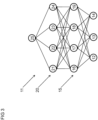
- FIG 3 shows a calibrated model in the form of a neural network 11.
- the neural network 11 of FIG 3 is employed to estimate cooling power and/or heating power Q ⁇ in,est .
- the neural network 11 of FIG 3 is employed to determine cooling power and/or heating power Q ⁇ in,est .
- the neural network 11 of FIG 3 is employed to calculate cooling power and/or heating power Q ⁇ in,est .
- the neural network 11 comprises input neurons 12 - 14.
- a first input neuron 12 corresponds to or is associated with a setpoint temperature.
- the setpoint temperature can, by way of non-limiting example, be a setpoint temperature of a site 2 and/or of a building 2.
- the setpoint temperature can, by way of another non-limiting example, also be a setpoint temperature of a zone and/or of a space and/or of a room.
- a second input neuron 13 corresponds to or is associated with a temperature ⁇ site at the site 2.
- the second input neuron 13 corresponds to or is associated with a temperature T building within the building 2.
- the second input neuron 13 corresponds to or is associated with a temperature T zone within a zone.
- the second input neuron 13 corresponds to or is associated with a temperature T space within a space. It is also envisaged that the second input neuron 13 corresponds to or is associated with a temperature T room within a room.
- a third input neuron 14 corresponds to or is associated with a control signal indicative of a valve position. More specifically, a third input neuron 14 can correspond to or be associated with a control signal indicative of a valve stroke. Ideally, a third input neuron 14 corresponds to or is associated with a valve position. More specifically, the third input neuron 14 can correspond to or be associated with a valve stroke.
- the neural network 11 also comprises an output neuron 25.
- the output neuron 25 corresponds to or is associated with an estimated intake of power Q ⁇ in,est .
- the estimated intake of power Q ⁇ in,est advantageously corresponds to an estimated cooling power and/or an estimated heating power.
- the estimated intake of power Q ⁇ in,est ideally is an estimated cooling power and/or an estimated heating power.
- the neural network 11 also comprises one or more hidden layers 15, 20, each layer 15, 20 having one or more hidden neurons 16 - 19, 21 - 24.
- the neural network 11 comprises two layers 15, 20 of hidden neurons.
- the neurons 16 - 19, 21 -24 are advantageously biased.
- the neural network 11 is ideally trained under test conditions. A series of measurements obtained under various test conditions is employed to train the neural network 11.
- the neural network 11 can, by way of non-limiting example, be trained by a supervised training algorithm such as backpropagation. It is also envisaged that neural network 11 is or has been trained using an evolutionary algorithm such as a genetic algorithm. The skilled artisan can combine training algorithms. A genetic algorithm can, by way of example, be employed to find a coarse estimate of the weights of the connections of neural network 11. A backpropagation algorithm is then employed to further improve on the performance of the network 11.
- the memory preferably is a non-volatile memory.
- the configuration of the neural network 11 and/or the weights of the connections of the neural network 11 define a procedure of estimating power intake Q ⁇ in,est .
- the procedure of estimating power intake Q ⁇ in,est preferably is a procedure of estimating cooling power and/or heating power.
- the procedure is advantageously applied to a site 2.
- the procedure can also be applied to a building 2.
- the procedure is advantageously applied to a zone within a site 2 or within a building 2.
- the procedure is ideally applied to a space such as a space within a site 2 or within a building 2.
- the procedure can also be applied to a room such as a room within a site 2 or within a building 2.
- the neural network comprises an input layer as outlined above.
- a first dense layer connects to the input layer.
- the first dense layer has 182 biased neurons.
- the first dense layer provides a plurality of connections to the previous layer.
- the number of connections to the previous layer is commensurate with the neurons of the input layer and with the neurons of the first dense layer.
- a second dense layer connects to the first dense layer.
- the second dense layer provides a plurality of connections to the previous layer.
- the number of connections to the previous layer is commensurate with the neurons of the first dense layer and with the neurons of the second dense layer.
- a third dense layer connects to the second dense layer.
- the third dense layer provides a plurality of connections to the previous layer.
- the number of connections to the previous layer is commensurate with the neurons of the second dense layer and with the neurons of the third dense layer.
- a fourth dense layer connects to the third dense layer.
- the fourth dense layer provides a plurality of connections to the previous layer.
- the number of connections to the previous layer is commensurate with the neurons of the third dense layer and with the neurons of the fourth dense layer.
- a fifth dense layer connects to the fourth dense layer.
- the fifth dense layer has a single biased output neuron.
- the fifth dense layer provides a plurality of connections to the previous layer.
- the number of connections to the previous layer is commensurate with the number of neurons of the fourth dense layer.
- the number of connections to the previous layer is also commensurate with the single neuron of the fifth dense layer.
- the calibrated network and/or the neural network 11 may employ single precision floating point numbers rather than double precision floating point numbers as weights.
- the calibrated network and/or the neural network 11 will require less memory.
- the neural network 11 is or has been trained using backpropagation. To that end, a data set is split into a training data set and a test data set. The sets contain data indicative of values provided to the input neurons of the network and indicative of the output neuron of the network.
- the trained neural network 11 can be employed to control a system for heating and/or ventilation and/or air-conditioning 1 at the site 2.
- the trained neural network 11 can also be employed to control a system for heating and/or ventilation 1 and/or air-conditioning at the building 2.
- the trained neural network 11 can still be employed to control a system for heating and/or ventilation and/or air-conditioning 1 within a zone.
- the zone can be a zone of a site or of a building 2.
- the trained neural network 11 can also be employed to control a system for heating and/or ventilation and/or air-conditioning 1 within a space.
- the space can be a space of a site or of a building 2.
- the trained neural network 11 can still be employed to control a system for heating and/or ventilation and/or air-conditioning 1 within a room.
- the room can be a room of a site or of a building 2.
- the trained neural network 11 can also be employed by a thermostat such as a smart thermostat.
- the thermostat can comprise a display and a processor.
- the processor of the thermostat estimates power intake Q ⁇ in,est via the neural network 11.
- the processor estimates cooling power and/or heating power Q ⁇ in,est via the neural network 11.
- the processor produces a graphics signal from the estimate and sends the estimate to the display.
- the display of the thermostat shows the estimate of power intake Q ⁇ in,est to a user and/or to an operator.
- the display of the thermostat advantageously shows the estimate of cooling power and/or heating power Q ⁇ in,est to a user and/or to an operator.
- the display of the thermostat shows the estimate to a user and/or to an operator via a graphical user interface.
- the trained neural network 11 can also be employed by a system controller 3.
- the system controller 3 can comprise a display and a processor.
- the processor of the system controller 3 estimates power intake Q ⁇ in,est via the neural network 11.
- the processor estimates cooling power and/or heating power Q ⁇ in,est via the neural network 11.
- the processor produces a graphics signal from the estimate and sends the estimate to the display.
- the display of the system controller 3 shows the estimate of power intake Q ⁇ in,est to a user and/or to an operator.
- the display of the system controller 3 advantageously shows the estimate of cooling power and/or heating power Q ⁇ in,est to a user and/or to an operator.
- the display of the system controller 3 shows the estimate to a user and/or to an operator via a graphical user interface.
- a grid operator can rely on one or more estimates produced by the neural network 11.
- the grid operator can, by way of non-limiting example, receive one or more estimates of power intake Q ⁇ in,est at the site 2. More specifically, the grid operator can receive one or more estimates of cooling power and/or of heating power at the site 2. The grid operator can then produce one or more demand response signals based on the received one or more estimates. The grid operator sends these one or more demand response signals back to the site 2. Power can then be curtailed at the site 2 in consequence of the one or more demand response signal.
- the grid operator can, by way of another non-limiting example, receive one or more estimates of power intake Q ⁇ in,est at a building 2. More specifically, the grid operator can receive one or more estimates of cooling power and/or of heating power at the building 2. The grid operator can then produce one or more demand response signals based on the received one or more estimates. The grid operator sends these one or more demand response signals back to the building 2. Power can then be curtailed at the building 2 in consequence of the one or more demand response signal.
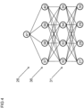
- the neural network 26 as shown in FIG 4 comprises input neurons 27 - 30.
- a first input neuron 27 corresponds to or is associated with a setpoint temperature.
- the setpoint temperature can, by way of non-limiting example, be a setpoint temperature of a site 2 and/or of a building 2.
- the setpoint temperature can, by way of another non-limiting example, also be a setpoint temperature of a zone and/or of a space and/or of a room.
- a second input neuron 28 corresponds to or is associated with a temperature T site at the site 2.
- the second input neuron 28 corresponds to or is associated with a temperature T building within the building 2.
- the second input neuron 28 corresponds to or is associated with a temperature T zone within a zone. In yet another embodiment, the second input neuron 28 corresponds to or is associated with a temperature T space within a space. It is also envisaged that the second input neuron 28 corresponds to or is associated with a temperature T room within a room.
- a third input neuron 29 corresponds to or is associated with a control signal indicative of a valve position. More specifically, a third input neuron 29 can correspond to or be associated with a control signal indicative of a valve stroke. Ideally, a third input neuron 29 corresponds to or is associated with a valve position. More specifically, the third input neuron 29 can correspond to or be associated with a valve stroke.
- a fourth input neuron 30 corresponds to or is associated with outside temperature T out .
- the neural network 26 also comprises an output neuron 41.
- the output neuron 41 corresponds to or is associated with an estimated intake of power Q ⁇ in,est .
- the estimated intake of power Q ⁇ in,est advantageously corresponds to an estimated cooling power and/or an estimated heating power.
- the estimated intake of power Q ⁇ in,est ideally is an estimated cooling power and/or an estimated heating power.
- the neural network 26 also comprises one or more hidden layers 31, 36, each layer 31, 36 having one or more hidden neurons 32 - 35, 37 - 40.
- the neural network 26 comprises two layers 31, 36 of hidden neurons.
- the neurons 32 - 35, 37 - 40 are advantageously biased.
- the neural network 26 is ideally trained under test conditions. A series of measurements obtained under various test conditions is employed to train the neural network 26.
- the neural network 26 can, by way of non-limiting example, be trained by a supervised training algorithm such as backpropagation. It is also envisaged that neural network 26 is or has been trained using an evolutionary algorithm such as a genetic algorithm. The skilled artisan can combine training algorithms. A genetic algorithm can, by way of example, be employed to find a coarse estimate of the weights of the connections of neural network 26. A backpropagation algorithm is then employed to further improve on the performance of the network 26.
- the configuration of the neural network 26 and/or the weights of the connections of neural network 26 are saved in a memory.
- the memory preferably is a non-volatile memory.
- the configuration of the neural network 26 and/or the weights of the connections of the neural network 26 define a procedure of estimating power intake Q ⁇ in,est .
- the procedure of estimating power intake Q ⁇ in,est preferably is a procedure of estimating cooling power and/or heating power.
- the procedure is advantageously applied to a site 2.
- the procedure can also be applied to a building 2.
- the procedure is advantageously applied to a zone within a site 2 or within a building 2.
- the procedure is ideally applied to a space such as a space within a site 2 or within a building 2.
- the procedure can also be applied to a room such as a room within a site 2 or within a building 2.
- the neural network comprises an input layer as outlined above.
- a first dense layer connects to the input layer.
- the first dense layer has 182 biased neurons.
- the first dense layer provides a plurality of connections to the previous layer.
- the number of connections to the previous layer is commensurate with the neurons of the input layer and with the neurons of the first dense layer.
- a second dense layer connects to the first dense layer.
- the second dense layer provides a plurality of connections to the previous layer.
- the number of connections to the previous layer is commensurate with the neurons of the first dense layer and with the neurons of the second dense layer.
- a third dense layer connects to the second dense layer.
- the third dense layer provides a plurality of connections to the previous layer.
- the number of connections to the previous layer is commensurate with the neurons of the second dense layer and with the neurons of the third dense layer.
- a fourth dense layer connects to the third dense layer.
- the fourth dense layer provides a plurality of connections to the previous layer.
- the number of connections to the previous layer is commensurate with the neurons of the third dense layer and with the neurons of the fourth dense layer.
- a fifth dense layer connects to the fourth dense layer.
- the fifth dense layer has a single biased output neuron.
- the fifth dense layer provides a plurality of connections to the previous layer.
- the number of connections to the previous layer is commensurate with the number of neurons of the fourth dense layer.
- the number of connections to the previous layer is also commensurate with the single neuron of the fifth dense layer.
- the calibrated network and/or the neural network 26 may employ single precision floating point numbers rather than double precision floating point numbers as weights.
- the calibrated network and/or the neural network 26 will require less memory.
- the neural network 26 is or has been trained using backpropagation. To that end, a data set is split into a training data set and a test data set. The sets contain data indicative of values provided to the input neurons of the network and indicative of the output neuron of the network.
- the trained neural network 26 can be employed to control a system for heating and/or ventilation and/or air-cond5itioning 1 at the site 2.
- the trained neural network 26 can also be employed to control a system for heating and/or ventilation 1 and/or air-conditioning at the building 2.
- the trained neural network 26 can still be employed to control a system for heating and/or ventilation and/or air-conditioning 1 within a zone.
- the zone can be a zone of a site or of a building 2.
- the trained neural network 26 can also be employed to control a system for heating and/or ventilation and/or air-conditioning 1 within a space.
- the space can be a space of a site or of a building 2.
- the trained neural network 26 can still be employed to control a system for heating and/or ventilation and/or air-conditioning 1 within a room.
- the room can be a room of a site or of a building 2.
- the trained neural network 26 can also be employed by a thermostat such as a smart thermostat.
- the thermostat can comprise a display and a processor.
- the processor of the thermostat estimates power intake Q ⁇ in,est via the neural network 26.
- the processor estimates cooling power and/or heating power Q ⁇ in,est via the neural network 26.
- the processor produces a graphics signal from the estimate and sends the estimate to the display.
- the display of the thermostat shows the estimate of power intake Q ⁇ in,est to a user and/or to an operator.
- the display of the thermostat advantageously shows the estimate of cooling power and/or heating power Q ⁇ in,est to a user and/or to an operator.
- the display of the thermostat shows the estimate to a user and/or to an operator via a graphical user interface.
- the trained neural network 26 can also be employed by a system controller 3.
- the system controller 3 can comprise a display and a processor.
- the processor of the system controller 3 estimates power intake Q ⁇ in,est via the neural network 26.
- the processor estimates cooling power and/or heating power Q ⁇ in,est via the neural network 26.
- the processor produces a graphics signal from the estimate and sends the estimate to the display.
- the display of the system controller 3 shows the estimate of power intake Q ⁇ in,est to a user and/or to an operator.
- the display of the system controller 3 advantageously shows the estimate of cooling power and/or heating power Q ⁇ in,est to a user and/or to an operator.
- the display of the system controller 3 shows the estimate to a user and/or to an operator via a graphical user interface.
- a grid operator can rely on one or more estimates produced by the neural network 26.
- the grid operator can, by way of non-limiting example, receive one or more estimates of power intake Q ⁇ in,est at the site 2. More specifically, the grid operator can receive one or more estimates of cooling power and/or of heating power at the site 2. The grid operator can then produce one or more demand response signals based on the received one or more estimates. The grid operator sends these one or more demand response signals back to the site 2. Power can then be curtailed at the site 2 in consequence of the one or more demand response signal.
- the grid operator can, by way of another non-limiting example, receive one or more estimates of power intake Q ⁇ in,est at a building 2. More specifically, the grid operator can receive one or more estimates of cooling power and/or of heating power at the building 2. The grid operator can then produce one or more demand response signals based on the received one or more estimates. The grid operator sends these one or more demand response signals back to the building 2. Power can then be curtailed at the building 2 in consequence of the one or more demand response signal.
- any steps of a method according to the present disclosure can be embodied in hardware and/or in a software module executed by a processor. Any steps of such a method can also be embodied in a software module executed by a processor inside a container using operating system level virtualisation. Any steps of such a method can still be embodied in a cloud computing arrangement. It is envisaged that any steps of a method according to the present disclosure is implemented in a combination of the above embodiments.
- the software may include a firmware and/or a hardware driver run by the operating system and/or an application program.
- the disclosure also relates to a computer program product for performing the operations presented herein. If implemented in software, the functions described may be stored as one or more instructions on a computer-readable medium.
- Storage media that can be used include, by way of non-limiting examples, random access memory (RAM) and/or read only memory (ROM) and/or flash memory.
- Storage media can, by way of non-limiting examples, also include EPROM memory and/or EEPROM memory and/or registers and/or a hard disk and/or a removable disk.
- Further storage media can, by way of non-limiting examples, include other optical disks and/or any available media that can be accessed by a computer.
- Storage media can still, by way of non-limiting example, include any other IT equipment and appliance.
- the present disclosure deals with a method of estimating a heat transfer Q ⁇ in,est via one or more thermal energy exchangers (4 - 8), the method comprising the steps of:
- the heat transfer Q ⁇ in,est comprises a cooling power and/or a heating power.
- the heat transfer Q ⁇ in,est is a cooling power and/or a heating power.
- the site (2) is a building (2). Consequently, the value of inside temperature T site at the site (2) is a value of inside temperature T building in the building (2). In another embodiment, the site (2) is a zone of a building (2). Consequently, the value of inside temperature T site at the site (2) is a value of inside temperature T zone in the zone of the building (2). According to still another embodiment, the site (2) is a space of a building (2). Consequently, the value of inside temperature T site at the site (2) is a value of inside temperature T space in the space of the building (2). According to yet another embodiment, the site (2) is a room of a building (2). Consequently, the value of inside temperature T site at the site (2) is a value of inside temperature T room in the room of the building (2).
- the method of estimating a heat transfer Q ⁇ in,est via one or more thermal energy exchangers (4 - 8) advantageously is a method of estimating a heat transfer Q ⁇ in,est via one or more thermal energy exchangers (4 - 8) of a site (2).
- the method of estimating a heat transfer Q ⁇ in,est via one or more thermal energy exchangers (4 - 8) preferably is a method of estimating a heat transfer Q ⁇ in,est via one or more thermal energy exchangers (4 - 8) of a building (2).
- the method of estimating a heat transfer Q ⁇ in,est via one or more thermal energy exchangers (4 - 8) ideally is a method of estimating a heat transfer Q ⁇ in,est via one or more thermal energy exchangers (4 - 8) of a zone of a building (2).
- the method of estimating a heat transfer Q ⁇ in,est via one or more thermal energy exchangers (4 - 8) can also be a method of estimating a heat transfer Q ⁇ in,est via one or more thermal energy exchangers (4-8) of a space of a building (2).
- the method of estimating a heat transfer Q ⁇ in,est via one or more thermal energy exchangers (4 - 8) can still be a method of estimating a heat transfer Q ⁇ in,est via one or more thermal energy exchangers (4 - 8) of a room of a building (2).
- the instant disclosure also deals with any of the aforementioned methods of estimating a heat transfer Q ⁇ in,est , the method comprising the step of: acquiring a signal indicative of a setpoint temperature for the site (2).
- the present disclosure further deals with any of the aforementioned methods of estimating a heat transfer Q ⁇ in,est , the method comprising the step of: acquiring a signal indicative of a setpoint temperature of the site (2).
- the instant disclosure still deals with any of the aforementioned methods of estimating a heat transfer Q ⁇ in,est , the method comprising the step of: acquiring a signal indicative of a setpoint temperature for the building (2).
- the present disclosure still further deals with any of the aforementioned methods of estimating a heat transfer Q ⁇ in,est , the method comprising the step of: acquiring a signal indicative of a setpoint temperature of the building (2).
- the instant disclosure yet further deals with any of the aforementioned methods of estimating a heat transfer Q ⁇ in,est , the method comprising the step of: acquiring a signal indicative of a setpoint temperature for the zone of the building (2).
- the present disclosure also deals with any of the aforementioned methods of estimating a heat transfer Q ⁇ in,est , the method comprising the step of: acquiring a signal indicative of a setpoint temperature of the zone of the building (2).
- the instant disclosure still deals with any of the aforementioned methods of estimating a heat transfer Q ⁇ in,est , the method comprising the step of: acquiring a signal indicative of a setpoint temperature for the space of the building (2).
- the present disclosure further deals with any of the aforementioned methods of estimating a heat transfer Q ⁇ in,est , the method comprising the step of: acquiring a signal indicative of a setpoint temperature of the space of the building (2).
- the instant disclosure still with any of the aforementioned methods of estimating a heat transfer Q ⁇ in,est , the method comprising the step of: acquiring a signal indicative of a setpoint temperature for the room of the building (2).
- the present disclosure still further deals with any of the aforementioned methods of estimating a heat transfer Q ⁇ in,est , the method comprising the step of: acquiring a signal indicative of a setpoint temperature of the room of the building (2).
- the calibrated model (11; 26) is or has been trained using a plurality of training data sets, each training data set comprising a value of setpoint temperature and a value of inside temperature T site at the site (2) and a value of position and a value of heat transfer Q ⁇ in . It is also envisaged that the calibrated model (11; 26) is or has been trained using a plurality of training data sets, each training data set comprising a training value of setpoint temperature and a training value of inside temperature ⁇ site at the site (2) and a training value of position and a training value of heat transfer Q ⁇ in .
- a heat meter can, by way of non-limiting example, be used to estimate and/or to determine the (training) value of heat transfer Q ⁇ in.
- the calibrated model (11; 26) is or has been tested using a plurality of test data sets, each test data set comprising a value of setpoint temperature and a value of inside temperature T site at the site (2) and a value of position and a value of heat transfer Q ⁇ in . It is also envisaged that the calibrated model (11; 26) is or has been tested using a plurality of test data sets, each test data set comprising a test value of setpoint temperature and a test value of inside temperature T site at the site (2) and a test value of position and a test value of heat transfer Q ⁇ in .
- a heat meter can, by way of non-limiting example, be used to estimate and/or to determine the (test) value of heat transfer Q ⁇ in .
- the calibrated model (11; 26) comprises a trained model. It is still envisaged that the calibrated model (11; 26) is a trained model.
- the trained model (11; 26) is or has been trained using a plurality of training data sets, each training data set comprising a value of setpoint temperature and a value of inside temperature T site at the site (2) and a value of position and a value of heat transfer Q ⁇ in . It is also envisaged that the trained model (11; 26) is or has been trained using a plurality of training data sets, each training data set comprising a training value of setpoint temperature and a training value of inside temperature T site at the site (2) and a training value of position and a training value of heat transfer Q ⁇ in .
- a heat meter can, by way of non-limiting example, be used to estimate and/or to determine the (training) value of heat transfer Q ⁇ in .
- the trained model (11; 26) is or has been tested using a plurality of test data sets, each test data set comprising a value of setpoint temperature and a value of inside temperature T site at the site (2) and a value of position and a value of heat transfer Q ⁇ in . It is also envisaged that the trained model (11; 26) is or has been tested using a plurality of test data sets, each test data set comprising a test value of setpoint temperature and a test value of inside temperature T site at the site (2) and a test value of position and a test value of heat transfer Q ⁇ in .
- a heat meter can, by way of non-limiting example, be used to estimate and/or to determine the (test) value of heat transfer Q ⁇ in .
- the instant disclosure deals with any of the methods described above, the method comprising the step of: using the calibrated model (11; 26) to estimate the heat transfer Q ⁇ in,est via the one or more thermal energy exchangers (4 - 8) based on the value of setpoint temperature and based on the value of inside temperature T site at the site (2) and based on the value of position.
- the calibrated model (11; 26) uses one or more rectified linear unit functions to estimate the heat transfer Q ⁇ in,est via the one or more thermal energy exchangers (4 - 8). Rectified linear unit functions mitigate issues due to vanishing gradients. Consequently, the model (11; 26) may perform its calculations using single precision variables rather than double precision variables as weights. The calibrated model (11; 26) then needs less memory.
- a calibrated model (11; 26) working with normalised input values generally provides more accurate estimates of heat transfer Q ⁇ in,est .
- the present disclosure also deals with any of the methods described above, the method comprising the steps of:
- the arithmetic mean is a weighted arithmetic mean.
- the arithmetic mean is a weighted arithmetic mean.
- the present disclosure still deals with any method of the methods described above, the method comprising the step of: using the calibrated model (11) to estimate the heat transfer Q ⁇ in,est via the one or more thermal energy exchangers (4 - 8) exclusively as a function of the value of setpoint temperature and of the value of inside temperature T site at the site (2) and of the value of position.
- the estimates apply to a plethora of sites (2).
- sites (2) comprise outside temperature sensors. That is, estimates of heat transfer Q ⁇ in,est via the one or more thermal energy exchangers (4 - 8) can also be provided for sites (2) having no outside temperature sensors.
- the instant disclosure still deals with any method of the methods described above and involving normalised input values, the method comprising the step of: using the calibrated model (11) to estimate the heat transfer Q ⁇ in,est via the one or more thermal energy exchangers (4 - 8) exclusively as a function of the normalised value of setpoint temperature and of the normalised value of inside temperature at the site (2) and of the normalised value of position.
- the present disclosure still deals with any method of the methods described above and involving an exclusive estimate of heat transfer Q ⁇ in,est , the method comprising the steps of:
- the instant disclosure still deals with any method of the methods described above and involving a value of outside temperature T out , the method comprising the step of: acquiring the signal indicative of the outside temperature outside the site (2) by reading the signal indicative of outside temperature from a sensor outside the site (2).
- the sensor outside the site (2) comprises a temperature sensor.
- the sensor outside the site (2) is a temperature sensor.
- the sensor outside the site (2) comprises a thermocouple.
- the sensor outside the site (2) is a thermocouple.
- a thermocouple can allow reuse of an existing or legacy thermocouple of an outside unit such as an outside manufacturing plant.
- the sensor outside the site (2) comprises a thermistor.
- the sensor outside the site (2) is a thermistor.
- a thermistor can allow reuse of an existing or legacy thermistor of an outside unit such as an outside fan coil unit.
- the sensor outside the site (2) comprises a fibre optic sensor.
- the sensor outside the site (2) is a fibre optic sensor. Fibre optic sensors provide benefits in hazardous environments.
- the instant disclosure still deals with any method of the methods described above and involving a value of outside temperature T out and not involving a temperature sensor, the method comprising the step of: acquiring the signal indicative of the outside temperature outside the site (2) by connecting to a computer network and by receiving from the network a data package comprising the signal indicative of the outside temperature and by extracting the signal indicative of the outside temperature from the data package.
- the present disclosure also deals with any of the methods described above involving an outside temperature, the method comprising the step of: acquiring the signal indicative of the outside temperature outside the site (2) by connecting to a network of interconnected computers and by receiving from the network a data package comprising the signal indicative of the outside temperature and by extracting the signal indicative of the outside temperature from the data package.
- the system can dispense with an outside temperature sensor if a signal indicative outside temperature is provided by an internet service provider.
- the present disclosure still deals with any method of the methods described above and involving a value of outside temperature T out , the method comprising the steps of:
- a calibrated model (26) working with normalised input values generally provides more accurate estimates of heat transfer Q ⁇ in,est .
- the instant disclosure still deals with any method of the methods described above and involving a value of outside temperature T out , the method comprising the step of: using the calibrated model (26) to estimate the heat transfer Q ⁇ in,est via the one or more thermal energy exchangers (4 - 8) exclusively as a function of the value of setpoint temperature and of the value of inside temperature T site at the site (2) and of the value of position and of the value of outside temperature T out .
- the estimates apply to a greater number of sites (2).
- information about the residential or industrial or commercial purpose of a site (2) is not always available. That is, estimates of heat transfer Q ⁇ in,est via the one or more thermal energy exchangers (4 - 8) can also be provided absent any knowledge of the purpose of the site (2).
- the present disclosure still deals with any method of the methods described above and involving a normalised value of outside temperature T out , the method comprising the step of: using the calibrated model (26) to estimate the heat transfer Q ⁇ in,est via the one or more thermal energy exchangers (4 - 8) exclusively as a function of the normalised value of setpoint temperature and of the normalised value of inside temperature at the site (2) and of the normalised value of position and of the normalised value of outside temperature.
- the present disclosure still deals with any method of the methods described above and involving an electric switch, wherein the electric switch connects the system for heating and/or ventilation and/or air-conditioning (1) to a power grid, the method comprising the step of:
- Curtailment of power otherwise delivered to a system for heating and/or ventilation and/or air-conditioning (1) protects the power grid from excessive demand. Any adverse influences of excessive demand caused by the system for heating and/or ventilation and/or air-conditioning (1) on the stability of the grid are mitigated thereby.
- the instant disclosure still deals with a device comprising a first interface for acquiring a signal indicative of a setpoint temperature, a second interface for acquiring a signal indicative of an inside temperature at a site (2), a third interface for acquiring one or more signals indicative of positions of valves of one or more thermal energy exchangers (4 - 8), a memory and a processor in operative communication with the memory, with the first interface, with the second interface, and with the third interface, the processor being configured to:
- the present disclosure also deals with a device comprising a first interface for acquiring a signal indicative of a setpoint temperature, a second interface for acquiring a signal indicative of an inside temperature at a site (2), a third interface for acquiring one or more signals indicative of positions of valves of one or more thermal energy exchangers (4 - 8), a memory and a processor in operative communication with the memory, with the first interface, with the second interface, and with the third interface, the processor being configured to:
- the instant disclosure still deals with a device comprising a first interface for acquiring a signal indicative of a setpoint temperature, a second interface for acquiring a signal indicative of an inside temperature at a site (2), a third interface for acquiring one or more signals indicative of positions of valves of one or more thermal energy exchangers (4 - 8), a fourth interface for acquiring a signal indicative of an outside temperature outside the site (2), a memory and a processor in operative communication with the memory, with the first interface, with the second interface, with the third interface, and with the fourth interface, the processor being configured to:
- the present disclosure still further deals with a device comprising a first interface for acquiring a signal indicative of a setpoint temperature, a second interface for acquiring a signal indicative of an inside temperature at a site (2), a third interface for acquiring one or more signals indicative of positions of valves of one or more thermal energy exchangers (4-8), a fifth interface for operating an electric switch, a memory and a processor in operative communication with the memory, with the first interface, with the second interface, with the third interface, and with the fifth interface, the processor being configured to:
- the instant disclosure yet further deals with a device comprising a first interface for acquiring a signal indicative of a setpoint temperature, a second interface for acquiring a signal indicative of an inside temperature at a site (2), a third interface for acquiring one or more signals indicative of positions of valves of one or more thermal energy exchangers (4 - 8), a fourth interface for acquiring a signal indicative of an outside temperature outside the site (2), a fifth interface for operating an electric switch, a memory and a processor in operative communication with the memory, with the first interface, with the second interface, with the third interface, with the fourth interface, and with the fifth interface, the processor being configured to:
- the devices of the instant disclosure preferably perform their methods using the calibrated models (11; 26) as read from the memories.
- the present disclosure also pertains to any of the devices of the present disclosure, wherein the memory has a capacity of one mebibyte or less.
- the calibrated model (11, 26) can be stored in a memory having a capacity of one mebibyte or less.
- the system thus relies on modest computational resources to estimate the heat transfer Q ⁇ in,est via the one or more thermal energy exchangers (4 - 8).
- the first, second, third, fourth, and fifth interfaces need not be mutually different.
- the same interface may read an inside temperature and read an outside temperature.
- the instant disclosure also pertains to a computer program comprising a set of instructions that when executed by one or more processors cause any of the devices as described above to perform any of the methods as described above.
- the present disclosure also deals with a computer program comprising a set of instructions that when executed by the processor of a device of the present disclosure cause the device to perform a method according to the present disclosure.
- the instant disclosure still further deals with a computer program product comprising a set of instructions that when executed by the processor of a device of the instant disclosure cause the device to perform a method according to the instant disclosure.
- the instant disclosure also deals with a computer-readable medium having stored thereon any of the computer programs of the instant disclosure.
- the present disclosure also deals with a computer-readable medium having stored thereon any of the computer program products of the present disclosure.
- the instant disclosure also pertains to any computer-readable medium of the computer-readable media of the instant disclosure, wherein the computer-readable medium has a capacity of one mebibyte or less.
- the instructions for estimating heat transfer Q ⁇ in,est can be stored on a computer-readable medium having a capacity of one mebibyte or less.
- the system thus relies on modest computational resources to estimate the heat transfer Q ⁇ in,est via the one or more thermal energy exchangers (4 - 8).
Landscapes
- Engineering & Computer Science (AREA)
- Physics & Mathematics (AREA)
- General Engineering & Computer Science (AREA)
- Chemical & Material Sciences (AREA)
- Combustion & Propulsion (AREA)
- General Physics & Mathematics (AREA)
- Theoretical Computer Science (AREA)
- Mechanical Engineering (AREA)
- Mathematical Physics (AREA)
- Health & Medical Sciences (AREA)
- Life Sciences & Earth Sciences (AREA)
- Computational Linguistics (AREA)
- Biophysics (AREA)
- Artificial Intelligence (AREA)
- Data Mining & Analysis (AREA)
- Evolutionary Computation (AREA)
- General Health & Medical Sciences (AREA)
- Molecular Biology (AREA)
- Computing Systems (AREA)
- Biomedical Technology (AREA)
- Software Systems (AREA)
- Signal Processing (AREA)
- Thermal Sciences (AREA)
- Fuzzy Systems (AREA)
- Human Computer Interaction (AREA)
- Bioinformatics & Cheminformatics (AREA)
- Bioinformatics & Computational Biology (AREA)
- Evolutionary Biology (AREA)
- Physiology (AREA)
- Automation & Control Theory (AREA)
- Air Conditioning Control Device (AREA)
Abstract
Description
- The present disclosure deals with estimating and/or determining an amount of power required for cooling or heating a site. More specifically, the present disclosure focuses on an amount of power required for cooling or heating a building such as a commercial and/or industrial and/or residential building.
- Installations for heating and/or ventilation, and/or air-conditioning (HVAC) are commonly made up of a plurality of circuits. Each circuit comprises one or several thermal energy exchangers to provide heating and/or cooling to various parts of a building. Thermal energy exchangers can be heating devices and/or cooling devices. A thermal energy exchanger of a domestic heating system can be a heat exchanger such as a radiator.
- Energy management systems and/or power management systems can control thermal loads of a site. More specifically, energy management systems and/or power management systems can control cooling and/or heating within a building. The building can, by way of non-limiting example, be a commercial and/or an industrial and/or a residential building.
- Buildings can employ hot-water tanks to store thermal energy such as heat. Likewise, coldwater storage tanks can be employed as buffers for coolants such as water. Also, storage ovens can store thermal energy to be released during the day. These examples of storage devices are not exhaustive.
- To minimise waste of power and to inhibit emissions of carbon dioxide, a daily amount of cooling power and/or of heating power shall be estimated in advance. Any deviation of such estimates from actual demand can result in an oversupply or in an undersupply of thermal power. If too much thermal energy is stored in a storage tank, an amount of power will be lost due to the excessive supply. If too little thermal energy is stored, a cooling and/or heating system may need to activate during the day and fill a gap between supply and demand.
- Also, occupants and operators of buildings are increasingly aware of the technical aspects of their use of thermal power. Occupants and operators are also increasingly aware of emissions of carbon dioxide caused by their use of thermal power. Operators can, by way of non-limiting example, investigate defects within a system for heating and/or ventilation and/or air-conditioning, if their use of thermal power beats expectations. Occupants also seek to minimise any environmental impacts of their cooling and/or heating. Those environmental impacts include, but are not limited to, emissions of carbon dioxide.
- That said, an estimate of the actual use of thermal power can depend on a plethora of factors. These factors include, but are not limited to:
- supply temperatures of thermal energy exchangers,
- return temperatures of thermal energy exchangers,
- valve positions at such thermal energy exchangers,
- setpoint temperatures for such thermal energy exchangers,
- room temperatures,
- outside temperatures,
- etc.
- Certain factors such as outside temperatures may not be readily available. A lack of a sensor for outside temperature may, by way of non-limiting example, exacerbate the problem of adequately estimating outside temperatures. The problem is further aggravated because buildings differ in their amounts of thermal insulation and/or in the type of heating system installed. Buildings may also differ in the efficiencies of their thermal energy exchangers. This list of differences between buildings is by no means exhaustive.
- It is thus far from certain whether one model can be applied to provide estimates of cooling power and/or of heating power that are at least fair. Even if there was such a model, it would not be trivial to limit the numbers of factors that impact on the results of such a model.
- A patent application
WO2015/061271A1 was filed by the University of Florida on 21 October 2014 . The application was published on 30 April 2015.WO2015/061271A1 deals with low-frequency ancillary power grid services. -
WO2015/061271A1 discloses a high-fidelity model. The high-fidelity model is calibrated such that it can predict temperatures within one or more zones. For calibration, data are collected from a building having a plurality of zones. To mitigate influences of solar radiation or of occupant heat gains, these data are collected at nighttime. - The model of temperature resembles a resistive-capacitive network. It provides a plurality of interconnected resistive-capacitive network models for the individual zones of the building. The model predicts changes of temperatures over time for individual zones as a function of its capacitive and resistive parameters. A least-squares approach is used to fit parameters of the model.
- The present disclosure deals with a method and a device for estimating a cooling power and/or a heating power. The cooling power and/or the heating power is a cooling power and/or heating power dissipated via a terminal unit such as a thermal energy exchanger. To that end, various input signals are collected. A setpoint temperature is an input signal. A temperature inside a site and/or a building and/or a zone and/or a space and/or a room forms another input signal. An indication of valve position is yet another input signal. The indication of valve position can, by way of non-limiting example, originate from a thermostat or from a smart thermostat. The indication of valve position can, by way of non-limiting example, originate from a system controller. These signals are processed. Values of setpoint temperature, of inside temperature, and of valve position are produced. A calibrated model such as a neural network receives the values at its input nodes. The calibrated model and/or the neural network then processes its inputs. The calibrated model and/or the neural network estimates a heat transfer in the form of a cooling power and/or a heating power via the terminal unit.
- The method and the device rely on a minimum of input parameters. The estimates produced by the calibrated model are fair with deviations from actual values being mostly less than twenty percent. In many cases, these estimates are even satisfactory. That is why the method, and the device are applicable to a plethora of sites and/or buildings.
- The inputs of the calibrated model and/or of the neural network can be normalised. Normalisation of input values yields even more accurate estimates of heat transfer. More specifically, normalisation of input values yields more accurate estimates of cooling power and/or of heating power.
- A site or a building can comprise a plurality of valves. In this case, it makes sense to determine a mean valve position. The mean valve position represents the valves in the building or at the site. More specifically, a weighted mean represents the valves in the building or at the site.
- To further improve on the accuracy of the estimates, an outside temperature can be factored into the estimate. The outside temperature can, by way of example, be read from a sensor or be received from a weather station. A value of outside temperature is then produced from the signal indicative of outside temperature. The calibrated model receives an additional input, the additional input being the value of outside temperature. More specifically, the neural network receives an additional input, the additional input being the value of outside temperature. The calibrated model and/or the neural network additionally processes the value of outside temperature. The calibrated model and/or the neural network estimates a heat transfer in the form of a cooling power and/or a heating power via the terminal unit.
- The value of outside temperature can also be normalised. Normalisation of outside temperature yields even more accurate estimates of heat transfer. More specifically, normalisation of outside temperature yields more accurate estimates of cooling power and/or of heating power.
- Where the estimates are exclusively based on setpoint temperatures, inside temperatures, outside temperatures, and valve positions, the results are still generally applicable. The estimates can be applied to most sites or buildings since outside temperatures can be received from a service provider. In other words, a limited number of input values yields estimates of heat transfer that deviate from actual values mostly by less than twenty percent. Deviations can in many cases be kept below ten percent.
- The outputs of the method and/or of the device can also be used to curtail power. It can become necessary to curtail power when the stability of the power grid is no longer guaranteed. A grid operator can then receive an estimate of cooling power and/or of heating power. The grid operator can then curtail power to a system for heating and/or ventilation and/or air-conditioning to maintain stability of the grid.
- Various features will become apparent to those skilled in the art from the following detailed description of the disclosed non-limiting embodiments. The drawings that accompany the detailed description can be briefly described as follows:
-
FIG 1 schematically shows various terminal units and a system controller of a heating and/or ventilation and/or air-conditioning system. -
FIG 2 is a schematical representation of flows of power into and out of a site. -
FIG 3 illustrates a first neural network for estimating cooling and/or heating power. -
FIG 4 illustrates a second neural network for estimating cooling and/or heating power. -
FIG 1 shows a system for heating and/or ventilation and/or air-conditioning 1. The system for heating and/or ventilation and/or air-conditioning 1 comprises asystem controller 3. Thesystem controller 3 can be arranged at asite 2 that is controlled by the system for heating and/or ventilation and/or air-conditioning 1. More specifically, thesystem controller 3 can be arranged inside abuilding 2 that is controlled by the system for heating and/or ventilation and/or air-conditioning 1. - The
system controller 3 can also be located remotely from asite 2 that is controlled by the system for heating and/or ventilation and/or air-conditioning 1. More specifically, thesystem controller 3 can be located remotely from abuilding 2 that is controlled by the system for heating and/or ventilation and/or air-conditioning 1. Thesystem controller 3 can, by way of non-limiting example, be located more than one kilometer from the site or from thebuilding 2. Thesystem controller 3 can, by way of another non-limiting example, be located more than ten kilometers from the site or from thebuilding 2. Thesystem controller 3 can, by way of yet another non-limiting example, be located more than one hundred kilometers from the site or from thebuilding 2. - The
system controller 3 advantageously comprises a power management system such as a power management system for thesite 2. Thesystem controller 3 ideally is a power management system such as a power management system for thesite 2. More specifically, thesystem controller 3 can comprise a power management system for thebuilding 2. Thesystem controller 3 can also be a power management system for thebuilding 2. - The system for heating and/or ventilation and/or air-conditioning 1 comprises at least one terminal unit 4 - 8. The system for heating and/or ventilation and/or air-conditioning 1 preferably comprises a plurality of terminal units 4 - 8. More specifically, a
site 2 can comprise at least one terminal unit 4 - 8. Thesite 2 preferably comprises a plurality of terminal units 4 - 8. More specifically, abuilding 2 can comprise at least one terminal unit 4 - 8. The
building 2 preferably comprises a plurality of terminal units 4 - 8. - At least one terminal unit 4 - 8 comprises a valve. The valve controls flow of a coolant and/or of a heating medium through the at least one terminal unit 4 - 8. According to an aspect of the system for heating and/or ventilation and/or air-conditioning 1, every terminal unit 4 - 8 comprises a valve. These valves control flows of a coolant and/or of a heating medium through their respective terminal units 4 - 8.
- It is envisaged that one or more terminal units 4 - 8 comprise a heating device such as a radiator. It is also envisaged that one or more terminal units 4 - 8 comprise cooling devices such as chilled beams.
- According to an aspect of the present disclosure, the one or more terminal units 4 - 8 comprise one or more thermal energy exchangers. According to another aspect of the present disclosure, the one or more terminal units 4 - 8 are one or more thermal energy exchangers.
- One or more of the terminal units 4 - 8 comprise a valve having a valve controller. The valve controller advantageously comprises a microcontroller and/or a microprocessor. In an embodiment, the valve controller is a microcontroller and/or is a microprocessor. The valve controller preferably comprises a memory such as a non-volatile memory.
- The valve controller ideally is or comprises an inexpensive and/or low-power system-on-a-chip microcontroller having integrated wireless connectivity. In a special embodiment, the system-on-a-chip microcontroller has a memory not exceeding one mebibyte. In another embodiment, the valve controller connects to an edge device.
- The one or more valve controllers of the one or more terminal units 4 - 8 can comprise thermostats such as smart thermostats. The one or more valve controllers of the one or more terminal units 4 - 8 can also be thermostats. More specifically, the one or more valve controllers of the one or more terminal units can be smart thermostats.
- The one or more valve controllers of the one or more terminal units 4 - 8 advantageously comprise one or more analog-to-digital converters. The one or more analog-to-digital converters provide conversion of analog signals into (digital) values. The one or more analog-to-digital converters can, by way of non-limiting example, convert signals indicative of valve positions into (digital) values. The one or more analog-to-digital converters can, by way of another non-limiting example, convert signals originating from temperature sensors into (digital) values. It is envisaged that the signals originating from temperature sensors are signals indicative of supply temperatures and/or indicative of temperatures at the
site 2. The signals originating from temperature sensors can also be signals indicative of temperatures outside thesite 2. - The one or more analog-to-digital converters can be integral parts of the one or more valve controllers of the one or more terminal units 4 - 8. That is, there are systems-on-a-chip, each system-on-a-chip having an analog-to-digital converter and a valve controller.
- The one or more valve controllers of the one or more terminal units 4 - 8 ideally comprise one or more sigma-delta converters. The one or more sigma-delta converters provide conversion of analog signals into (digital) values. The one or more sigma-delta converters can, by way of non-limiting example, convert signals indicative of valve positions into (digital) values. The one or more sigma-delta converters can, by way of another non-limiting example, convert signals originating from temperature sensors into (digital) values. It is envisaged that the signals originating from temperature sensors are signals indicative of supply temperatures and/or indicative of temperatures at the
site 2. The signals originating from temperature sensors can also be signals indicative of temperatures outside thesite 2. - The one or more sigma-delta converters can be integral parts of the one or more valve controllers of the one or more terminal units 4 - 8. That is, there are systems-on-a-chip, each system-on-a-chip having a sigma-delta converter and a valve controller.
- The valve controller is in operative communication with the
system controller 3. A connection between the valve controller and thesystem controller 3 can be bidirectional. A bidirectional connection affords flexibility. A connection between the valve controller and thesystem controller 3 can also be unidirectional. Communication from the valve controller to thesystem controller 3 is facilitated by such a unidirectional connection. A unidirectional connection reduces complexity. - A communication link between the valve controller and the
system controller 3 can, for example, rely on wireless solutions such as WLAN and/or KNX® RF. A communication link between the valve controller and thesystem controller 3 can, for example, also rely on wireless solutions such as Thread and/or Zigbee and/or EnOcean®. The wireless communication link preferably involves a digital communication bus. The wireless communication link preferably involves a digital communication protocol. - A communication link between the valve controller and the
system controller 3 can, for example, also rely on hard-wired connections such as Ethernet® cables and/or on KNX® cables. The hard-wired communication link preferably involves a digital communication bus. The hard-wired communication link preferably involves a digital communication protocol. - According to an aspect of the present disclosure, all the terminal units 4 - 8 comprise a valve having a valve controller. The valve controllers advantageously each comprise a microcontroller and/or a microprocessor. In an embodiment, the valve controllers are microcontrollers and/or microprocessors. The valve controllers preferably each comprise a memory such as a non-volatile memory.
- The valve controllers ideally are or comprise inexpensive and/or low-power system-on-a-chip microcontrollers, each system-on-a-chip microcontroller having integrated wireless connectivity. In a special embodiment, the system-on-a-chip microcontrollers each have a memory not exceeding one mebibyte.
- The valve controllers advantageously comprise analog-to-digital converters. The analog-to-digital converters provide conversion of analog signals into (digital) values. The analog-to-digital converters can, by way of non-limiting example, convert signals indicative of valve positions into (digital) values. The analog-to-digital converters can, by way of another non-limiting example, convert signals originating from temperature sensors into (digital) values. It is envisaged that the signals originating from temperature sensors are signals indicative of supply temperatures and/or indicative of temperatures at the
site 2. The signals originating from temperature sensors can also be signals indicative of temperatures outside thesite 2. - The analog-to-digital converters can be integral parts of the valve controllers of the terminal units 4 - 8. That is, there are systems-on-a-chip, each system-on-a-chip having an analog-to-digital converter and a valve controller.
- The valve controllers ideally comprise sigma-delta converters. The sigma-delta converters provide conversion of analog signals into (digital) values. The sigma-delta converters can, by way of non-limiting example, convert signals indicative of valve positions into (digital) values. The sigma-delta converters can, by way of another non-limiting example, convert signals originating from temperature sensors into (digital) values. It is envisaged that the signals originating from temperature sensors are signals indicative of supply temperatures and/or indicative of temperatures at the
site 2. The signals originating from temperature sensors can also be signals indicative of temperatures outside thesite 2. - The sigma-delta converters can be integral parts of the valve controllers of the terminal units 4 - 8. That is, there are systems-on-a-chip, each system-on-a-chip having a sigma-delta converter and a valve controller.
- The valve controllers are in operative communication with the
system controller 3. Connections between the valve controllers and thesystem controller 3 can be bidirectional. Bidirectional connections afford flexibility. Connections between the valve controller and thesystem controller 3 can also be unidirectional. Communication from the valve controllers to thesystem controller 3 is facilitated by such unidirectional connections. Unidirectional connections reduce complexity. - In an embodiment, the valve controllers connect to the
system controller 3 in a hub and spoke topology. Alternatively, a network having a mesh topology connects the valve controllers to thesystem controller 3. In a special embodiment, the valve controllers and thesystem controller 3 form a full-mesh topology network. - A network comprising the valve controllers and the
system controller 3 can, for example, rely on wireless solutions such as WLAN and/or KNX® RF and/or Thread. A network comprising the valve controllers and thesystem controller 3 can, for example, also rely on wireless solutions such as Zigbee, and/or EnOcean®. Any communication within the wireless network preferably involves a digital communication bus. Any communication within the wireless network preferably involves a digital communication protocol. - A network comprising the valve controllers and the
system controller 3 can, for example, also rely on hard-wired connections such as Ethernet® cables and/or on KNX® cables. Any communication within the hard-wired network preferably involves a digital communication bus. Any communication within the hard-wired network preferably involves a digital communication protocol. - It is envisaged that the
system controller 3 can identify valve controllers of terminal units 4-8. Identification can, by way of example, take place based on machine addresses of such valve controllers. That is, the valve controllers and/or the memories of the valve controllers store such machine addresses. Thesystem controller 3 will then use a lookup table to identify the controllers of the terminal units 4 - 8. Identification can, by way of another example, take place based on vendor identities and/or product identities of such valve controllers. That is, the valve controllers and/or the memories of the valve controllers store such vendor identities and/or product identities. Accordingly, the valve controllers send their vendor identities and/or product identities to thesystem controller 3 for identification purposes. - Advantageously, the
system controller 3 is operable to configure one or more of the valve controllers of the terminal units 4 - 8. In so doing, thesystem controller 3 can provide the one or more valve controllers data such as baud rates and/or logical addresses. Thesystem controller 3 can also provide the one or more valve controllers data such as setpoints of room temperature. Thesystem controller 3 can further provide the one or more valve controllers data such as setpoints of temperature within a zone. - Where the valve controllers are battery-operated, the valve controllers are preferably operable to receive signals indicative of the charging levels of their respective batteries. The valve controllers then produce values of charging levels based on these signals. Where a charging level is less than a threshold such as a predefined threshold, a low-battery alarm signal can be sent to the
system controller 3. - The
system controller 3 advantageously comprises one or more analog-to-digital converters. The one or more analog-to-digital converters provide conversion of analog signals into (digital) values. The one or more analog-to-digital converters can, by way of non-limiting example, convert signals indicative of valve positions into (digital) values. The one or more analog-to-digital converters can, by way of another non-limiting example, convert signals originating from temperature sensors into (digital) values. It is envisaged that the signals originating from temperature sensors are signals indicative of supply temperatures and/or indicative of temperatures at thesite 2. The signals originating from temperature sensors can also be signals indicative of temperatures outside thesite 2. - The one or more analog-to-digital converters can be integral parts of the
system controller 3 of the terminal units 4 - 8. That is, there is a systems-on-a-chip having one or more analog-to-digital converters and thesystem controller 3. - The
system controller 3 ideally comprises one or more sigma-delta converters. The one or more sigma-delta converters provide conversion of analog signals into (digital) values. The one or more sigma-delta converters can, by way of non-limiting example, convert signals indicative of valve positions into (digital) values. The one or more sigma-delta converters can, by way of another non-limiting example, convert signals originating from temperature sensors into (digital) values. It is envisaged that the signals originating from temperature sensors are signals indicative of supply temperatures and/or indicative of temperatures at thesite 2. The signals originating from temperature sensors can also be signals indicative of temperatures outside thesite 2. - The one or more sigma-delta converters can be integral parts of the
system controller 3 of the terminal units 4 - 8. That is, there is a systems-on-a-chip having one or more sigma-delta converters and thesystem controller 3. - Now turning to
FIG 2 , anarrow 9 indicative of power intake of thesite 2 and anarrow 10 indicative of power losses of thesite 2 are shown. More specifically,FIG 2 illustrates flows ofpower building 2. - The power intake of the
site 2 depends on the one or more positions of the one or more valves of the terminal units 4 - 8. More specifically, the intake of thebuilding 2 depends on the one or more positions of the one or more valves of the terminal units 4 - 8. The intake of thesite 2 also depends on a setpoint temperature. - The one or more positions of the one or more valves of the terminal units 4 - 8 are readily available by way of measurements. The one or more positions of the one or more valves of the terminal units 4 - 8 can also be derived from one or more control signals. The control signals can, by way of non-limiting example, be produced and transmitted by the
system controller 3. The control signals can, by of another non-limiting example, also be produced and transmitted by the one or more valve controllers of the terminal units 4 - 8. The control signals can, by of another non-limiting example, also be produced and transmitted by one or more thermostats of the system 1. More specifically, the control signals can be produced and transmitted by one or more thermostats of thesite 2. The control signals can still be produced and transmitted by one or more thermostats of thebuilding 2. - The one or more supply temperatures of the one or more valves of the terminal units 4 - 8 are readily available by way of measurements. To that end, one or more valves of the terminal units 4 - 8 can comprise one or more temperature sensors such as one or more thermocouples. The one or more temperature sensors are typically arranged in communication with the supply ends of the one or more valves. The one or more temperature sensors are preferably arranged in direct communication with the supply ends of the one or more valves.
- The one or more supply temperatures of the one or more terminal units 4 - 8 can also be readily available by way of measurements. To that end, the one or more terminal units 4 - 8 can comprise one or more temperature sensors such as one or more thermocouples. The one or more temperature sensors are typically arranged in communication with the supply ends of the one or more terminal units 4 - 8. The one or more temperature sensors are preferably arranged in direct communication with the supply ends of the one or more terminal units 4 - 8.
- By contrast, the power intake Q̇in of the
site 2 is in many cases not readily available by way of measurements. Instead, the power intake Q̇in of thesite 2 needs be estimated based on quantities such as the one or more valve positions. The power intake Q̇in of thesite 2 can also be estimated based on quantities such as a setpoint temperature. The power intake Q̇in can be estimated based on the one or more valve positions and based on a setpoint temperature. - More specifically, the power intake Q̇in of the
building 2 is in many cases not readily available by way of measurements. Instead, the power intake Q̇in of thebuilding 2 needs be estimated based on quantities such as the one or more valve positions. The power intake Q̇in of thebuilding 2 can also be estimated based on quantities such as a setpoint temperature. The power intake Q̇in can be estimated based on the one or more valve positions and based on a setpoint temperature. - Likewise, the power losses Q̇out of the
site 2 are in many cases not readily available by way of measurements. Instead, the power losses Q̇out of thesite 2 need be estimated based on quantities such as the outside temperature. The power losses Q̇out of thesite 2 can also be estimated based on quantities such as one or more values of room temperature. The one or more values of room temperature are typically room temperatures of one or more zones within thesite 2. The one or more values of room temperature can also be room temperatures of one or more spaces within thesite 2. The one or more values of room temperature can also be room temperatures of one or more rooms within thesite 2. - The power losses Q̇out of the
building 2 are in many cases not readily available by way of measurements. Instead, the power losses Q̇out of thebuilding 2 need be estimated based on quantities such as the outside temperature. The power losses Q̇out of thebuilding 2 can also be estimated based on quantities such as one or more values of room temperature. The one or more values of room temperature are typically room temperatures of one or more zones within thebuilding 2. The one or more values of room temperature can also be room temperatures of one or more spaces within thebuilding 2. The one or more values of room temperature can also be room temperatures of one or more rooms within thebuilding 2. - The power losses Q̇out of the
site 2 can also be estimated based on one or more setpoints of temperature. The one or more setpoints of temperature can, by way of non-limiting example, be produced and transmitted by thesystem controller 3. The setpoints can, by of another non-limiting example, also be produced and transmitted by the one or more valve controllers of the terminal units 4 - 8. The one or more setpoints can, by of another non-limiting example, also be produced and transmitted by one or more thermostats of the system 1. More specifically, the one or more setpoints of temperature can be produced and transmitted by one or more thermostats of thesite 2. The one or more setpoints of temperature can still be produced and transmitted by one or more thermostats of thebuilding 2. - In an embodiment, the power losses Q̇out of the
site 2 are estimated based on outside temperature and based on values of room temperature. The power losses Q̇out of thesite 2 can also be determined based on outside temperature and based on values of room temperature. The power losses Q̇out of thesite 2 can still be calculated based on outside temperature and based on values of room temperature. - More specifically, the power losses Q̇out of the
building 2 are estimated based on outside temperature and based on values of room temperature. The power losses Q̇out of thebuilding 2 can also be determined based on outside temperature and based on values of room temperature. The power losses Q̇out of thebuilding 2 can still be calculated based on outside temperature and based on values of room temperature. - In another embodiment, the power losses Q̇out of the
site 2 are estimated based on outside temperature and based on setpoints of temperature. The power losses Q̇out of thesite 2 can also be determined based on outside temperature and based on setpoints of temperature. The power losses Q̇out of thesite 2 can still be calculated based on outside temperature and based on setpoints of temperature. - More specifically, the power losses Q̇out of the
building 2 are estimated based on outside temperature and based on setpoints of temperature. The power losses Q̇out of thebuilding 2 can also be determined based on outside temperature and based on setpoints of temperature. The power losses Q̇out of thebuilding 2 can still be calculated based on outside temperature and based on setpoints of temperature. - In still another embodiment, the power losses Q̇out of the
site 2 are estimated based on values of room temperature and based on setpoints of temperature. The power losses Q̇out of thesite 2 can also be determined based on values of room temperature and based on setpoints of temperature. The power losses Q̇out of thesite 2 can still be calculated based on values of room temperature and based on setpoints of temperature. - More specifically, the power losses Q̇out of the
building 2 are estimated based on values of room temperature and based on setpoints of temperature. The power losses Q̇out of thebuilding 2 can also be determined based on values of room temperature and based on setpoints of temperature. The power losses Q̇out of thebuilding 2 can still be calculated based on values of room temperature and based on setpoints of temperature. - In yet another embodiment, the power losses Q̇out of the
site 2 are estimated based on outside temperature and on values of room temperature. Setpoints of temperature are also factored into the estimates of power losses Q̇out of thesite 2. The power losses Q̇out of thesite 2 can be determined based on outside temperature and on values of room temperature. Setpoints of temperature are also factored into the determinations of power losses Q̇out of thesite 2. The power losses Q̇out of thesite 2 can still be calculated based on outside temperature and on values of room temperature and on setpoints of temperature. Setpoints of temperature are also factored into the calculations of power losses Q̇out of thesite 2. - More specifically, the power losses Q̇out of the
building 2 are estimated based on outside temperature and on values of room temperature. Setpoints of temperature are also factored into the estimates of power losses Q̇out of thebuilding 2. The power losses Q̇out of thebuilding 2 can also be determined based on outside temperature and on values of room temperature. Setpoints of temperature are also factored into the determinations of power losses Q̇out of thebuilding 2. The power losses Q̇out of thebuilding 2 can still be calculated based on outside temperature and on values of room temperature. Setpoints of temperature are also factored into the calculations of power losses Q̇out of thebuilding 2. - Changes in power Q̇site of a
site 2 versus time are a function of power intake Q̇in and a function of power losses Q̇out :
- These changes in power Q̇site relate to changes in temperature Ṫsite at the
site 2 via a value of specific heat ch :
- It follows that


- Where power losses are a function of the temperature Tsite at the
site 2 and of outside temperature Tout , the above relationship can be rewritten:
- If power losses Q̇out are governed by convective heat transfer, a linear relationship will apply:

- The power intake Q̇in,est of the
site 2 can then be estimated as
- The power intake Q̇in,est of the
site 2 as estimated according to the above relationship depends strongly on short-term changes of the temperature Tsite. Those changes can, by way of non-limiting examples, be caused by windows opened, solar radiation, blind positions, etc. - It is envisaged that the temperature Tsite at the
site 2 is a mean temperature Tsite at thesite 2. The mean temperature Tsite is preferably an arithmetic mean of temperatures at thesite 2. The mean temperature Tsite can also be a geometric mean of temperatures at thesite 2. In a preferred embodiment, the temperature Tsite at thesite 2 is produced from a signal of a sensor arranged at thesite 2. It is also envisaged that the changes in temperature Tsite at thesite 2 are mean changes in temperature Tsite at thesite 2. The mean changes in temperature Tsite are preferably arithmetic means of changes in temperature at thesite 2. The mean changes in temperature Tsite can also be geometric means of changes in temperature at thesite 2. - A sensor outside the
site 2 can record a signal indicative of an outside temperature Tout. An outside temperature Tout can then be produced from such a signal. Where a sensor outside thesite 2 is unavailable, an outside temperature Tout can be received from a nearby weather station. An outside temperature Tout is advantageously received from a service provider via a computer network. For example, thesystem controller 3 can receive an outside temperature Tout from a service provider via a computer network. A thermostat can, by way of non-limiting example, receive an outside temperature Tout from a service provider via a computer network. Also, a valve controller of a valve of the one or more terminal units 4 - 8 can receive an outside temperature Tout. The outside temperature Tout can be received from a service provider via a computer network such as the internet. - More specifically, changes in power Q̇building of a
building 2 versus time are a function of power intake Q̇in and a function of power losses Q̇out :
- These changes in power Q̇building relate to changes in temperature Ṫbuilding at the
building 2 via a value of specific heat ch :
- It follows that


- Where power losses are a function of the temperature Tbuilding at the
building 2 and of outside temperature Tout , the above relationship can be rewritten:
- If power losses Q̇out are governed by convective heat transfer, a linear relationship will apply:

- The power intake Q̇in,est of the
building 2 as estimated according to the above relationship depends strongly on short-term changes of the temperature Tbuilding. Those changes can, by way of non-limiting examples, be caused by windows opened, solar radiation, blind positions, etc. - The power intake Q̇in,est of the
building 2 can then be estimated as
- It is envisaged that the temperature Tbuilding in the
building 2 is a mean temperature Tbuilding in thebuilding 2. The mean temperature Tbuilding is preferably an arithmetic mean of temperatures within thebuilding 2. The mean temperature Tbuilding can also be a geometric mean of temperatures within thebuilding 2. In a preferred embodiment, the temperature Tbuilding in thebuilding 2 is produced from a signal of a sensor arranged in thebuilding 2. It is also envisaged that the changes in temperature Tbuilding at thebuilding 2 are mean changes in temperature within thebuilding 2. The mean changes in temperature Ṫbuilding are preferably arithmetic means of changes in temperature within thebuilding 2. The mean changes in temperature Tbuilding can also be geometric means of changes in temperature within thebuilding 2. - A sensor outside the
building 2 can record a signal indicative of an outside temperature Tout. An outside temperature Tout can then be produced from such a signal. Where a sensor outside thebuilding 2 is unavailable, an outside temperature Tout can be received from a nearby weather station. An outside temperature Tout is advantageously received from a service provider via a computer network. For example, thesystem controller 3 can receive an outside temperature Tout from a service provider via a computer network. A thermostat can, by way of non-limiting example, receive an outside temperature Tout from a service provider via a computer network. Also, a valve controller of a valve of the one or more terminal units 4 - 8 can receive an outside temperature Tout. The outside temperature Tout can be received from a service provider via a computer network such as the internet. - Also, changes in power Q̇zone of a zone versus time are a function of power intake Q̇in and a function of power losses Q̇out :

- These changes in power Qzone relate to changes in temperature Ṫzone within the zone via a value of specific heat ch :

- It follows that


- Where power losses are a function of the temperature Tzone in the zone and of outside temperature Tout , the above relationship can be rewritten:

- If power losses Q̇out are governed by convective heat transfer, a linear relationship will apply:

- The power intake Q̇in,est of the zone can then be estimated as

- The power intake Q̇in,est of the zone as estimated according to the above relationship depends strongly on short-term changes of the temperature Tzone. Those changes can, by way of non-limiting examples, be caused by windows opened, solar radiation, blind positions, etc.
- It is envisaged that the temperature Tzone in the zone is a mean temperature Tzone in the zone. The mean temperature Tzone is preferably an arithmetic mean of temperatures within the zone. The mean temperature Tzone can also be a geometric mean of temperatures within the zone. In a preferred embodiment, the temperature Tzone in the zone is produced from a signal of a sensor arranged in the zone. It is also envisaged that the changes in temperature Ṫzone in the zone are mean changes in temperature in the zone. The mean changes in temperature Ṫzone are preferably arithmetic means of changes in temperature within the zone. The mean changes in temperature Ṫzone can also be geometric means of changes in temperature within the zone.
- A sensor outside the
site 2 and outside the zone can record a signal indicative of an outside temperature Tout. An outside temperature Tout can then be produced from such a signal. Where a sensor outside thesite 2 and outside the zone is unavailable, an outside temperature Tout can be received from a nearby weather station. An outside temperature Tout is advantageously received from a service provider via a computer network. For example, thesystem controller 3 can receive an outside temperature Tout from a service provider via a computer network. A thermostat can, by way of non-limiting example, receive an outside temperature Tout from a service provider via a computer network. Also, a valve controller of a valve of the one or more terminal units 4 - 8 can receive an outside temperature Tout. The outside temperature Tout can be received from a service provider via a computer network such as the internet. - Still more specifically, changes in power Q̇space of a space versus time are a function of power intake Q̇in and a function of power losses Q̇out :

- These changes in power Q̇space relate to changes in temperature Ṫspace within the space via a value of specific heat ch :

- It follows that


- Where power losses are a function of the temperature Tspace in the space and of outside temperature Tout , the above relationship can be rewritten:

- If power losses Q̇out are governed by convective heat transfer, a linear relationship will apply:

- The power intake Q̇in,est of the space can then be estimated as

- The power intake Q̇in,est of the space as estimated according to the above relationship depends strongly on short-term changes of the temperature Tspace. Those changes can, by way of non-limiting examples, be caused by windows opened, solar radiation, blind positions, etc.
- It is envisaged that the temperature Tspace in the space is a mean temperature Tspace in the space. The mean temperature Tspace is preferably an arithmetic mean of temperatures within the space. The mean temperature Tspace can also be a geometric mean of temperatures within the space. In a preferred embodiment, the temperature Tspace in the space is produced from a signal of a sensor arranged in the space. It is also envisaged that the changes in temperature Tspace in the space are mean changes in temperature in the space. The mean changes in temperature Tspace are preferably arithmetic means of changes in temperature within the space. The mean changes in temperature Tspace can also be geometric means of changes in temperature within the space.
- A sensor outside the
site 2 and outside the space can record a signal indicative of an outside temperature Tout. An outside temperature Tout can then be produced from such a signal. Where a sensor outside thesite 2 and outside the space is unavailable, an outside temperature Tout can be received from a nearby weather station. An outside temperature Tout is advantageously received from a service provider via a computer network. For example, thesystem controller 3 can receive an outside temperature Tout from a service provider via a computer network. A thermostat can, by way of non-limiting example, receive an outside temperature Tout from a service provider via a computer network. Also, a valve controller of a valve of the one or more terminal units 4 - 8 can receive an outside temperature Tout. The outside temperature Tout can be received from a service provider via a computer network such as the internet. - Yet more specifically, changes in power Q̇room of a room versus time are a function of power intake Q̇in and a function of power losses Q̇out :

- These changes in power Q̇room relate to changes in temperature Ṫroom within the room via a value of specific heat ch :

- It follows that


- Where power losses are a function of the temperature Troom in the room and of outside temperature Tout , the above relationship can be rewritten:

- If power losses Q̇out are governed by convective heat transfer, a linear relationship will apply:

- The power intake Q̇in,est of the room can then be estimated as

- The power intake Q̇in,est of the room as estimated according to the above relationship depends strongly on short-term changes of the temperature Troom. Those changes can, by way of non-limiting examples, be caused by windows opened, solar radiation, blinds positions, etc.
- It is envisaged that the temperature Troom in the room is a mean temperature Troom in the room. The mean temperature Troom is preferably an arithmetic mean of temperatures within the room. The mean temperature Troom can also be a geometric mean of temperatures within the room. In a preferred embodiment, the temperature Troom in the room is produced from a signal of a sensor arranged in the room. It is also envisaged that the changes in temperature Ṫroom in the room are mean changes in temperature in the room. The mean changes in temperature Ṫroom are preferably arithmetic means of changes in temperature within the room. The mean changes in temperature Ṫroom can also be geometric means of changes in temperature within the room.
- A sensor outside the
site 2 and outside the room can record a signal indicative of an outside temperature Tout. An outside temperature Tout can then be produced from such a signal. Where a sensor outside thesite 2 and outside the room is unavailable, an outside temperature Tout can be received from a nearby weather station. An outside temperature Tout is advantageously received from a service provider via a computer network. For example, thesystem controller 3 can receive an outside temperature Tout from a service provider via a computer network. A thermostat can, by way of non-limiting example, receive an outside temperature Tout from a service provider via a computer network. Also, a valve controller of a valve of the one or more terminal units 4 - 8 can receive an outside temperature Tout. The outside temperature Tout can be received from a service provider via a computer network such as the internet. - To mitigate adverse influence of short-term fluctuations of temperature, an approach involving artificial intelligence is chosen.
FIG 3 shows a calibrated model in the form of aneural network 11. Theneural network 11 ofFIG 3 is employed to estimate cooling power and/or heating power Q̇in,est. Advantageously, theneural network 11 ofFIG 3 is employed to determine cooling power and/or heating power Q̇in,est. Ideally, theneural network 11 ofFIG 3 is employed to calculate cooling power and/or heating power Q̇in,est. - The
neural network 11 comprises input neurons 12 - 14. Preferably, afirst input neuron 12 corresponds to or is associated with a setpoint temperature. The setpoint temperature can, by way of non-limiting example, be a setpoint temperature of asite 2 and/or of abuilding 2. The setpoint temperature can, by way of another non-limiting example, also be a setpoint temperature of a zone and/or of a space and/or of a room. In an embodiment, asecond input neuron 13 corresponds to or is associated with a temperature Ṫsite at thesite 2. In another embodiment, thesecond input neuron 13 corresponds to or is associated with a temperature Tbuilding within thebuilding 2. In still another embodiment, thesecond input neuron 13 corresponds to or is associated with a temperature Tzone within a zone. In yet another embodiment, thesecond input neuron 13 corresponds to or is associated with a temperature Tspace within a space. It is also envisaged that thesecond input neuron 13 corresponds to or is associated with a temperature Troom within a room. Preferably, athird input neuron 14 corresponds to or is associated with a control signal indicative of a valve position. More specifically, athird input neuron 14 can correspond to or be associated with a control signal indicative of a valve stroke. Ideally, athird input neuron 14 corresponds to or is associated with a valve position. More specifically, thethird input neuron 14 can correspond to or be associated with a valve stroke. - Any input to the
neural network 11 is ideally normalised. Theneural network 11 also comprises anoutput neuron 25. Theoutput neuron 25 corresponds to or is associated with an estimated intake of power Q̇in,est. The estimated intake of power Q̇in,est advantageously corresponds to an estimated cooling power and/or an estimated heating power. The estimated intake of power Q̇in,est ideally is an estimated cooling power and/or an estimated heating power. - The
neural network 11 also comprises one or morehidden layers layer neural network 11 comprises twolayers 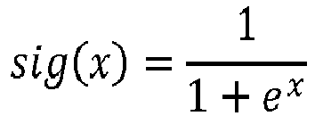
neural network 11 is ideally trained under test conditions. A series of measurements obtained under various test conditions is employed to train theneural network 11. - The
neural network 11 can, by way of non-limiting example, be trained by a supervised training algorithm such as backpropagation. It is also envisaged thatneural network 11 is or has been trained using an evolutionary algorithm such as a genetic algorithm. The skilled artisan can combine training algorithms. A genetic algorithm can, by way of example, be employed to find a coarse estimate of the weights of the connections ofneural network 11. A backpropagation algorithm is then employed to further improve on the performance of thenetwork 11. - After training the configuration of
neural network 11 and/or the weights of the connections ofneural network 11 are saved in a memory. The memory preferably is a non-volatile memory. The configuration of theneural network 11 and/or the weights of the connections of theneural network 11 define a procedure of estimating power intake Q̇in,est. The procedure of estimating power intake Q̇in,est preferably is a procedure of estimating cooling power and/or heating power. The procedure is advantageously applied to asite 2. The procedure can also be applied to abuilding 2. The procedure is advantageously applied to a zone within asite 2 or within abuilding 2. The procedure is ideally applied to a space such as a space within asite 2 or within abuilding 2. The procedure can also be applied to a room such as a room within asite 2 or within abuilding 2. - In practise, the neural network comprises an input layer as outlined above. A first dense layer connects to the input layer. The first dense layer has 182 biased neurons. Each of these neurons has a rectified linear unit (relu) activation function:

- The first dense layer provides a plurality of connections to the previous layer. The number of connections to the previous layer is commensurate with the neurons of the input layer and with the neurons of the first dense layer. A second dense layer connects to the first dense layer. The second dense layer has 182 biased neurons. Each of these neurons has a rectified linear unit (relu) activation function:

- The second dense layer provides a plurality of connections to the previous layer. The number of connections to the previous layer is commensurate with the neurons of the first dense layer and with the neurons of the second dense layer. A third dense layer connects to the second dense layer. The third dense layer has 182 biased neurons. Each of these neurons has a rectified linear unit (relu) activation function:

- The third dense layer provides a plurality of connections to the previous layer. The number of connections to the previous layer is commensurate with the neurons of the second dense layer and with the neurons of the third dense layer. A fourth dense layer connects to the third dense layer. The fourth dense layer has 182 biased neurons. Each of these neurons has a rectified linear unit (relu) activation function:

- The fourth dense layer provides a plurality of connections to the previous layer. The number of connections to the previous layer is commensurate with the neurons of the third dense layer and with the neurons of the fourth dense layer. A fifth dense layer connects to the fourth dense layer. The fifth dense layer has a single biased output neuron. The output neuron has a linear activation function:

- The fifth dense layer provides a plurality of connections to the previous layer. The number of connections to the previous layer is commensurate with the number of neurons of the fourth dense layer. The number of connections to the previous layer is also commensurate with the single neuron of the fifth dense layer.
- Activation functions in the form of rectified linear unit functions mitigate issues due to vanishing gradients. Consequently, the calibrated network and/or the
neural network 11 may employ single precision floating point numbers rather than double precision floating point numbers as weights. The calibrated network and/or theneural network 11 will require less memory. - The
neural network 11 is or has been trained using backpropagation. To that end, a data set is split into a training data set and a test data set. The sets contain data indicative of values provided to the input neurons of the network and indicative of the output neuron of the network. The below table provides examples of such data:setpoint temperature site temperature Tsite / valve position intake of power Q̇in building temperature Tbuilding / zone temperature Tzone / space temperature Tspace / room temperature Troom 292.15 Kelvin 292.02 Kelvin 28.5 % 26.0 W 292.15 Kelvin 291.99 Kelvin 37.1 % 119 W 292.15 Kelvin 291.98 Kelvin 43.4 % 313 W 292.15 Kelvin 291.97 Kelvin 48.4 % 460 W 292.15 Kelvin 291.97 Kelvin 52.6 % 568 W - The trained
neural network 11 can be employed to control a system for heating and/or ventilation and/or air-conditioning 1 at thesite 2. The trainedneural network 11 can also be employed to control a system for heating and/or ventilation 1 and/or air-conditioning at thebuilding 2. The trainedneural network 11 can still be employed to control a system for heating and/or ventilation and/or air-conditioning 1 within a zone. The zone can be a zone of a site or of abuilding 2. The trainedneural network 11 can also be employed to control a system for heating and/or ventilation and/or air-conditioning 1 within a space. The space can be a space of a site or of abuilding 2. The trainedneural network 11 can still be employed to control a system for heating and/or ventilation and/or air-conditioning 1 within a room. The room can be a room of a site or of abuilding 2. - The trained
neural network 11 can also be employed by a thermostat such as a smart thermostat. The thermostat can comprise a display and a processor. The processor of the thermostat estimates power intake Q̇in,est via theneural network 11. Preferably, the processor estimates cooling power and/or heating power Q̇in,est via theneural network 11. The processor produces a graphics signal from the estimate and sends the estimate to the display. The display of the thermostat shows the estimate of power intake Q̇in,est to a user and/or to an operator. The display of the thermostat advantageously shows the estimate of cooling power and/or heating power Q̇in,est to a user and/or to an operator. Preferably, the display of the thermostat shows the estimate to a user and/or to an operator via a graphical user interface. - The trained
neural network 11 can also be employed by asystem controller 3. Thesystem controller 3 can comprise a display and a processor. The processor of thesystem controller 3 estimates power intake Q̇in,est via theneural network 11. Preferably, the processor estimates cooling power and/or heating power Q̇in,est via theneural network 11. The processor produces a graphics signal from the estimate and sends the estimate to the display. The display of thesystem controller 3 shows the estimate of power intake Q̇in,est to a user and/or to an operator. The display of thesystem controller 3 advantageously shows the estimate of cooling power and/or heating power Q̇in,est to a user and/or to an operator. Preferably, the display of thesystem controller 3 shows the estimate to a user and/or to an operator via a graphical user interface. - A grid operator can rely on one or more estimates produced by the
neural network 11. The grid operator can, by way of non-limiting example, receive one or more estimates of power intake Q̇in,est at thesite 2. More specifically, the grid operator can receive one or more estimates of cooling power and/or of heating power at thesite 2. The grid operator can then produce one or more demand response signals based on the received one or more estimates. The grid operator sends these one or more demand response signals back to thesite 2. Power can then be curtailed at thesite 2 in consequence of the one or more demand response signal. - The grid operator can, by way of another non-limiting example, receive one or more estimates of power intake Q̇in,est at a
building 2. More specifically, the grid operator can receive one or more estimates of cooling power and/or of heating power at thebuilding 2. The grid operator can then produce one or more demand response signals based on the received one or more estimates. The grid operator sends these one or more demand response signals back to thebuilding 2. Power can then be curtailed at thebuilding 2 in consequence of the one or more demand response signal. - The
neural network 26 as shown inFIG 4 comprises input neurons 27 - 30. Preferably, afirst input neuron 27 corresponds to or is associated with a setpoint temperature. The setpoint temperature can, by way of non-limiting example, be a setpoint temperature of asite 2 and/or of abuilding 2. The setpoint temperature can, by way of another non-limiting example, also be a setpoint temperature of a zone and/or of a space and/or of a room. In an embodiment, asecond input neuron 28 corresponds to or is associated with a temperature Tsite at thesite 2. In another embodiment, thesecond input neuron 28 corresponds to or is associated with a temperature Tbuilding within thebuilding 2. In still another embodiment, thesecond input neuron 28 corresponds to or is associated with a temperature Tzone within a zone. In yet another embodiment, thesecond input neuron 28 corresponds to or is associated with a temperature Tspace within a space. It is also envisaged that thesecond input neuron 28 corresponds to or is associated with a temperature Troom within a room. Preferably, athird input neuron 29 corresponds to or is associated with a control signal indicative of a valve position. More specifically, athird input neuron 29 can correspond to or be associated with a control signal indicative of a valve stroke. Ideally, athird input neuron 29 corresponds to or is associated with a valve position. More specifically, thethird input neuron 29 can correspond to or be associated with a valve stroke. Afourth input neuron 30 corresponds to or is associated with outside temperature Tout. - Any input to the
neural network 26 is ideally normalised. Theneural network 26 also comprises anoutput neuron 41. Theoutput neuron 41 corresponds to or is associated with an estimated intake of power Q̇in,est. The estimated intake of power Q̇in,est advantageously corresponds to an estimated cooling power and/or an estimated heating power. The estimated intake of power Q̇in,est ideally is an estimated cooling power and/or an estimated heating power. - The
neural network 26 also comprises one or morehidden layers layer neural network 26 comprises twolayers 
neural network 26 is ideally trained under test conditions. A series of measurements obtained under various test conditions is employed to train theneural network 26. - The
neural network 26 can, by way of non-limiting example, be trained by a supervised training algorithm such as backpropagation. It is also envisaged thatneural network 26 is or has been trained using an evolutionary algorithm such as a genetic algorithm. The skilled artisan can combine training algorithms. A genetic algorithm can, by way of example, be employed to find a coarse estimate of the weights of the connections ofneural network 26. A backpropagation algorithm is then employed to further improve on the performance of thenetwork 26. - After training the configuration of
neural network 26 and/or the weights of the connections ofneural network 26 are saved in a memory. The memory preferably is a non-volatile memory. The configuration of theneural network 26 and/or the weights of the connections of theneural network 26 define a procedure of estimating power intake Q̇in,est. The procedure of estimating power intake Q̇in,est preferably is a procedure of estimating cooling power and/or heating power. The procedure is advantageously applied to asite 2. The procedure can also be applied to abuilding 2. The procedure is advantageously applied to a zone within asite 2 or within abuilding 2. The procedure is ideally applied to a space such as a space within asite 2 or within abuilding 2. The procedure can also be applied to a room such as a room within asite 2 or within abuilding 2. - In practise, the neural network comprises an input layer as outlined above. A first dense layer connects to the input layer. The first dense layer has 182 biased neurons. Each of these neurons has a rectified linear unit (relu) activation function:

- The first dense layer provides a plurality of connections to the previous layer. The number of connections to the previous layer is commensurate with the neurons of the input layer and with the neurons of the first dense layer. A second dense layer connects to the first dense layer. The second dense layer has 182 biased neurons. Each of these neurons has a rectified linear unit (relu) activation function:

- The second dense layer provides a plurality of connections to the previous layer. The number of connections to the previous layer is commensurate with the neurons of the first dense layer and with the neurons of the second dense layer. A third dense layer connects to the second dense layer. The third dense layer has 182 biased neurons. Each of these neurons has a rectified linear unit (relu) activation function:

- The third dense layer provides a plurality of connections to the previous layer. The number of connections to the previous layer is commensurate with the neurons of the second dense layer and with the neurons of the third dense layer. A fourth dense layer connects to the third dense layer. The fourth dense layer has 182 biased neurons. Each of these neurons has a rectified linear unit (relu) activation function:

- The fourth dense layer provides a plurality of connections to the previous layer. The number of connections to the previous layer is commensurate with the neurons of the third dense layer and with the neurons of the fourth dense layer. A fifth dense layer connects to the fourth dense layer. The fifth dense layer has a single biased output neuron. The output neuron has a linear activation function:

- The fifth dense layer provides a plurality of connections to the previous layer. The number of connections to the previous layer is commensurate with the number of neurons of the fourth dense layer. The number of connections to the previous layer is also commensurate with the single neuron of the fifth dense layer.
- Activation functions in the form of rectified linear unit functions mitigate issues due to vanishing gradients. Consequently, the calibrated network and/or the
neural network 26 may employ single precision floating point numbers rather than double precision floating point numbers as weights. The calibrated network and/or theneural network 26 will require less memory. - The
neural network 26 is or has been trained using backpropagation. To that end, a data set is split into a training data set and a test data set. The sets contain data indicative of values provided to the input neurons of the network and indicative of the output neuron of the network. The below table provides examples of such data:setpoint temperature site temperature Tsite / valve position outside temperature Tout intake of power Q̇in building temperature Tbuildingl zone temperature Tzone / space temperature Tspace / room temperature Troom 292.15 Kelvin 292.02 Kelvin 28.5 % 279.45 Kelvin 26.0 W 292.15 Kelvin 291.99 Kelvin 37.1 % 277.51 Kelvin 119 W 292.15 Kelvin 291.98 Kelvin 43.4 % 278.69 Kelvin 313 W 292.15 Kelvin 291.97 Kelvin 48.4 % 276.33 Kelvin 460 W 292.15 Kelvin 291.97 Kelvin 52.6 % 271.85 Kelvin 568 W - The trained
neural network 26 can be employed to control a system for heating and/or ventilation and/or air-cond5itioning 1 at thesite 2. The trainedneural network 26 can also be employed to control a system for heating and/or ventilation 1 and/or air-conditioning at thebuilding 2. The trainedneural network 26 can still be employed to control a system for heating and/or ventilation and/or air-conditioning 1 within a zone. The zone can be a zone of a site or of abuilding 2. The trainedneural network 26 can also be employed to control a system for heating and/or ventilation and/or air-conditioning 1 within a space. The space can be a space of a site or of abuilding 2. The trainedneural network 26 can still be employed to control a system for heating and/or ventilation and/or air-conditioning 1 within a room. The room can be a room of a site or of abuilding 2. - The trained
neural network 26 can also be employed by a thermostat such as a smart thermostat. The thermostat can comprise a display and a processor. The processor of the thermostat estimates power intake Q̇in,est via theneural network 26. Preferably, the processor estimates cooling power and/or heating power Q̇in,est via theneural network 26. The processor produces a graphics signal from the estimate and sends the estimate to the display. The display of the thermostat shows the estimate of power intake Q̇in,est to a user and/or to an operator. The display of the thermostat advantageously shows the estimate of cooling power and/or heating power Q̇in,est to a user and/or to an operator. Preferably, the display of the thermostat shows the estimate to a user and/or to an operator via a graphical user interface. - The trained
neural network 26 can also be employed by asystem controller 3. Thesystem controller 3 can comprise a display and a processor. The processor of thesystem controller 3 estimates power intake Q̇in,est via theneural network 26. Preferably, the processor estimates cooling power and/or heating power Q̇in,est via theneural network 26. The processor produces a graphics signal from the estimate and sends the estimate to the display. The display of thesystem controller 3 shows the estimate of power intake Q̇in,est to a user and/or to an operator. The display of thesystem controller 3 advantageously shows the estimate of cooling power and/or heating power Q̇in,est to a user and/or to an operator. - Preferably, the display of the
system controller 3 shows the estimate to a user and/or to an operator via a graphical user interface. - A grid operator can rely on one or more estimates produced by the
neural network 26. The grid operator can, by way of non-limiting example, receive one or more estimates of power intake Q̇in,est at thesite 2. More specifically, the grid operator can receive one or more estimates of cooling power and/or of heating power at thesite 2. The grid operator can then produce one or more demand response signals based on the received one or more estimates. The grid operator sends these one or more demand response signals back to thesite 2. Power can then be curtailed at thesite 2 in consequence of the one or more demand response signal. - The grid operator can, by way of another non-limiting example, receive one or more estimates of power intake Q̇in,est at a
building 2. More specifically, the grid operator can receive one or more estimates of cooling power and/or of heating power at thebuilding 2. The grid operator can then produce one or more demand response signals based on the received one or more estimates. The grid operator sends these one or more demand response signals back to thebuilding 2. Power can then be curtailed at thebuilding 2 in consequence of the one or more demand response signal. - Any steps of a method according to the present disclosure can be embodied in hardware and/or in a software module executed by a processor. Any steps of such a method can also be embodied in a software module executed by a processor inside a container using operating system level virtualisation. Any steps of such a method can still be embodied in a cloud computing arrangement. It is envisaged that any steps of a method according to the present disclosure is implemented in a combination of the above embodiments. The software may include a firmware and/or a hardware driver run by the operating system and/or an application program. Thus, the disclosure also relates to a computer program product for performing the operations presented herein. If implemented in software, the functions described may be stored as one or more instructions on a computer-readable medium. Storage media that can be used include, by way of non-limiting examples, random access memory (RAM) and/or read only memory (ROM) and/or flash memory. Storage media can, by way of non-limiting examples, also include EPROM memory and/or EEPROM memory and/or registers and/or a hard disk and/or a removable disk. Further storage media can, by way of non-limiting examples, include other optical disks and/or any available media that can be accessed by a computer. Storage media can still, by way of non-limiting example, include any other IT equipment and appliance.
- As described in detail herein, the present disclosure deals with a method of estimating a heat transfer Q̇in,est via one or more thermal energy exchangers (4 - 8), the method comprising the steps of:
- acquiring a signal indicative of a setpoint temperature;
- acquiring a signal indicative of an inside temperature at a site (2);
- acquiring one or more signals indicative of positions of valves of the one or more thermal energy exchangers (4 - 8);
- producing a value of setpoint temperature from the signal indicative of the setpoint temperature;
- producing a value of inside temperature Tsite at the site (2) from the signal indicative of inside temperature;
- producing a value of position from the one or more signals indicative of positions of the valves;
- providing a calibrated model (11; 26) with the value of setpoint temperature and with the value of inside temperature Tsite at the site (2) and with the value of position; and
- using the calibrated model (11; 26) to estimate the heat transfer Q̇in,est via the one or more thermal energy exchangers (4 - 8).
- According to an aspect of the present disclosure, the heat transfer Q̇in,est comprises a cooling power and/or a heating power. According to a special aspect of the present disclosure, the heat transfer Q̇in,est is a cooling power and/or a heating power.
- In an embodiment, the site (2) is a building (2). Consequently, the value of inside temperature Tsite at the site (2) is a value of inside temperature Tbuilding in the building (2). In another embodiment, the site (2) is a zone of a building (2). Consequently, the value of inside temperature Tsite at the site (2) is a value of inside temperature Tzone in the zone of the building (2). According to still another embodiment, the site (2) is a space of a building (2). Consequently, the value of inside temperature Tsite at the site (2) is a value of inside temperature Tspace in the space of the building (2). According to yet another embodiment, the site (2) is a room of a building (2). Consequently, the value of inside temperature Tsite at the site (2) is a value of inside temperature Troom in the room of the building (2).
- The method of estimating a heat transfer Q̇in,est via one or more thermal energy exchangers (4 - 8) advantageously is a method of estimating a heat transfer Q̇in,est via one or more thermal energy exchangers (4 - 8) of a site (2). The method of estimating a heat transfer Q̇in,est via one or more thermal energy exchangers (4 - 8) preferably is a method of estimating a heat transfer Q̇in,est via one or more thermal energy exchangers (4 - 8) of a building (2). The method of estimating a heat transfer Q̇in,est via one or more thermal energy exchangers (4 - 8) ideally is a method of estimating a heat transfer Q̇in,est via one or more thermal energy exchangers (4 - 8) of a zone of a building (2). The method of estimating a heat transfer Q̇in,est via one or more thermal energy exchangers (4 - 8) can also be a method of estimating a heat transfer Q̇in,est via one or more thermal energy exchangers (4-8) of a space of a building (2). The method of estimating a heat transfer Q̇in,est via one or more thermal energy exchangers (4 - 8) can still be a method of estimating a heat transfer Q̇in,est via one or more thermal energy exchangers (4 - 8) of a room of a building (2).
- The instant disclosure also deals with any of the aforementioned methods of estimating a heat transfer Q̇in,est , the method comprising the step of:
acquiring a signal indicative of a setpoint temperature for the site (2). - The present disclosure further deals with any of the aforementioned methods of estimating a heat transfer Q̇in,est , the method comprising the step of:
acquiring a signal indicative of a setpoint temperature of the site (2). - The instant disclosure still deals with any of the aforementioned methods of estimating a heat transfer Q̇in,est , the method comprising the step of:
acquiring a signal indicative of a setpoint temperature for the building (2). - The present disclosure still further deals with any of the aforementioned methods of estimating a heat transfer Q̇in,est , the method comprising the step of:
acquiring a signal indicative of a setpoint temperature of the building (2). - The instant disclosure yet further deals with any of the aforementioned methods of estimating a heat transfer Q̇in,est, the method comprising the step of:
acquiring a signal indicative of a setpoint temperature for the zone of the building (2). - The present disclosure also deals with any of the aforementioned methods of estimating a heat transfer Q̇in,est , the method comprising the step of:
acquiring a signal indicative of a setpoint temperature of the zone of the building (2). - The instant disclosure still deals with any of the aforementioned methods of estimating a heat transfer Q̇in,est , the method comprising the step of:
acquiring a signal indicative of a setpoint temperature for the space of the building (2). - The present disclosure further deals with any of the aforementioned methods of estimating a heat transfer Q̇in,est , the method comprising the step of:
acquiring a signal indicative of a setpoint temperature of the space of the building (2). - The instant disclosure still with any of the aforementioned methods of estimating a heat transfer Q̇in,est , the method comprising the step of:
acquiring a signal indicative of a setpoint temperature for the room of the building (2). - The present disclosure still further deals with any of the aforementioned methods of estimating a heat transfer Q̇in,est , the method comprising the step of:
acquiring a signal indicative of a setpoint temperature of the room of the building (2). - It is envisaged that the calibrated model (11; 26) is or has been trained using a plurality of training data sets, each training data set comprising a value of setpoint temperature and a value of inside temperature Tsite at the site (2) and a value of position and a value of heat transfer Q̇in. It is also envisaged that the calibrated model (11; 26) is or has been trained using a plurality of training data sets, each training data set comprising a training value of setpoint temperature and a training value of inside temperature Ṫsite at the site (2) and a training value of position and a training value of heat transfer Q̇in. A heat meter can, by way of non-limiting example, be used to estimate and/or to determine the (training) value of heat transfer Q̇in.
- It is envisaged that the calibrated model (11; 26) is or has been tested using a plurality of test data sets, each test data set comprising a value of setpoint temperature and a value of inside temperature Tsite at the site (2) and a value of position and a value of heat transfer Q̇in. It is also envisaged that the calibrated model (11; 26) is or has been tested using a plurality of test data sets, each test data set comprising a test value of setpoint temperature and a test value of inside temperature Tsite at the site (2) and a test value of position and a test value of heat transfer Q̇in. A heat meter can, by way of non-limiting example, be used to estimate and/or to determine the (test) value of heat transfer Q̇in.
- It is envisaged that the calibrated model (11; 26) comprises a trained model. It is still envisaged that the calibrated model (11; 26) is a trained model.
- It is envisaged that the trained model (11; 26) is or has been trained using a plurality of training data sets, each training data set comprising a value of setpoint temperature and a value of inside temperature Tsite at the site (2) and a value of position and a value of heat transfer Q̇in. It is also envisaged that the trained model (11; 26) is or has been trained using a plurality of training data sets, each training data set comprising a training value of setpoint temperature and a training value of inside temperature Tsite at the site (2) and a training value of position and a training value of heat transfer Q̇in. A heat meter can, by way of non-limiting example, be used to estimate and/or to determine the (training) value of heat transfer Q̇in.
- It is envisaged that the trained model (11; 26) is or has been tested using a plurality of test data sets, each test data set comprising a value of setpoint temperature and a value of inside temperature Tsite at the site (2) and a value of position and a value of heat transfer Q̇in. It is also envisaged that the trained model (11; 26) is or has been tested using a plurality of test data sets, each test data set comprising a test value of setpoint temperature and a test value of inside temperature Tsite at the site (2) and a test value of position and a test value of heat transfer Q̇in. A heat meter can, by way of non-limiting example, be used to estimate and/or to determine the (test) value of heat transfer Q̇in.
- The instant disclosure deals with any of the methods described above, the method comprising the step of:
using the calibrated model (11; 26) to estimate the heat transfer Q̇in,est via the one or more thermal energy exchangers (4 - 8) based on the value of setpoint temperature and based on the value of inside temperature Tsite at the site (2) and based on the value of position. - In an embodiment, the calibrated model (11; 26) uses one or more rectified linear unit functions to estimate the heat transfer Q̇in,est via the one or more thermal energy exchangers (4 - 8). Rectified linear unit functions mitigate issues due to vanishing gradients. Consequently, the model (11; 26) may perform its calculations using single precision variables rather than double precision variables as weights. The calibrated model (11; 26) then needs less memory.
- The instant disclosure still deals with any method of the methods described above, the method comprising the steps of:
- using the calibrated model (11; 26) to normalise the value of setpoint temperature;
- using the calibrated model (11; 26) to normalise the value of inside temperature Tsite at the site (2);
- using the calibrated model (11; 26) to normalise the value of position; and
- using the calibrated model (11; 26) to estimate the heat transfer Q̇in,est via the one or more thermal energy exchangers (4 - 8) based on the normalised value of setpoint temperature and based on the normalised value of inside temperature at the site (2) and based on the normalised value of position.
- A calibrated model (11; 26) working with normalised input values generally provides more accurate estimates of heat transfer Q̇in,est.
- The present disclosure still deals with any method of the methods described above, the method comprising the steps of:
- producing one or more individual values by producing an individual value from each signal indicative of a position of a valve; and
- producing the value of position by determining a mean of the one or more individual values.
- The present disclosure also deals with any of the methods described above, the method comprising the steps of:
- producing one or more individual values by producing an individual value from each signal indicative of a position of a valve; and
- producing the value of position by determining an arithmetic mean of the one or more individual values.
- In an embodiment, the arithmetic mean is a weighted arithmetic mean.
- The instant disclosure still deals with any of the methods described above, the method comprising the steps of:
- producing one or more individual values by producing an individual value from each signal indicative of a position of a valve; and
- producing the value of position by determining a geometric mean of the one or more individual values.
- The present disclosure still further deals with any of the methods described above, the method comprising the steps of:
- producing one or more individual values by producing an individual value from each signal indicative of a position of a valve; and
- producing the value of position by calculating an arithmetic mean of the one or more individual values.
- In an embodiment, the arithmetic mean is a weighted arithmetic mean.
- The instant disclosure yet further deals with any of the methods described above, the method comprising the steps of:
- producing one or more individual values by producing an individual value from each signal indicative of a position of a valve; and
- producing the value of position by calculating a geometric mean of the one or more individual values.
- The present disclosure still deals with any method of the methods described above, the method comprising the step of:
using the calibrated model (11) to estimate the heat transfer Q̇in,est via the one or more thermal energy exchangers (4 - 8) exclusively as a function of the value of setpoint temperature and of the value of inside temperature Tsite at the site (2) and of the value of position. - By limiting the number of input values of the calibrated model (11), the estimates apply to a plethora of sites (2). For example, not all sites (2) comprise outside temperature sensors. That is, estimates of heat transfer Q̇in,est via the one or more thermal energy exchangers (4 - 8) can also be provided for sites (2) having no outside temperature sensors.
- The instant disclosure still deals with any method of the methods described above and involving normalised input values, the method comprising the step of:
using the calibrated model (11) to estimate the heat transfer Q̇in,est via the one or more thermal energy exchangers (4 - 8) exclusively as a function of the normalised value of setpoint temperature and of the normalised value of inside temperature at the site (2) and of the normalised value of position. - The present disclosure still deals with any method of the methods described above and involving an exclusive estimate of heat transfer Q̇in,est , the method comprising the steps of:
- acquiring a signal indicative of an outside temperature outside the site (2);
- producing a value of outside temperature Tout from the signal indicative of outside temperature;
- providing the calibrated model (26) with the value of setpoint temperature and with the value of inside temperature Tsite at the site (2) and with the value of position and with the value of outside temperature Tout ; and
- using the calibrated model (26) to estimate the heat transfer Q̇in,est via the one or more thermal energy exchangers (4 - 8) based on the value of setpoint temperature and based on the value of inside temperature Tsite at the site (2) and based on the value of position and based on the value of outside temperature Tout.
- The instant disclosure still deals with any method of the methods described above and involving a value of outside temperature Tout , the method comprising the step of:
acquiring the signal indicative of the outside temperature outside the site (2) by reading the signal indicative of outside temperature from a sensor outside the site (2). - According to an aspect of the present disclosure, the sensor outside the site (2) comprises a temperature sensor. According to a special aspect of the present disclosure, the sensor outside the site (2) is a temperature sensor. According to an aspect of the instant disclosure, the sensor outside the site (2) comprises a thermocouple. According to a special aspect of the instant disclosure, the sensor outside the site (2) is a thermocouple. A thermocouple can allow reuse of an existing or legacy thermocouple of an outside unit such as an outside manufacturing plant. According to an aspect of the instant disclosure, the sensor outside the site (2) comprises a thermistor. According to a special aspect of the instant disclosure, the sensor outside the site (2) is a thermistor. A thermistor can allow reuse of an existing or legacy thermistor of an outside unit such as an outside fan coil unit. According to an aspect of the present disclosure, the sensor outside the site (2) comprises a fibre optic sensor. According to a special aspect of the present disclosure, the sensor outside the site (2) is a fibre optic sensor. Fibre optic sensors provide benefits in hazardous environments.
- The instant disclosure still deals with any method of the methods described above and involving a value of outside temperature T out and not involving a temperature sensor, the method comprising the step of:
acquiring the signal indicative of the outside temperature outside the site (2) by connecting to a computer network and by receiving from the network a data package comprising the signal indicative of the outside temperature and by extracting the signal indicative of the outside temperature from the data package. - The present disclosure also deals with any of the methods described above involving an outside temperature, the method comprising the step of:
acquiring the signal indicative of the outside temperature outside the site (2) by connecting to a network of interconnected computers and by receiving from the network a data package comprising the signal indicative of the outside temperature and by extracting the signal indicative of the outside temperature from the data package. - The system can dispense with an outside temperature sensor if a signal indicative outside temperature is provided by an internet service provider.
- The present disclosure still deals with any method of the methods described above and involving a value of outside temperature T out, the method comprising the steps of:
- using the calibrated model (26) to normalise the value of setpoint temperature;
- using the calibrated model (26) to normalise the value of inside temperature Tsite at the site (2);
- using the calibrated model (26) to normalise the value of position;
- using the calibrated model (26) to normalise the value of outside temperature T out; and
- using the calibrated model (26) to estimate the heat transfer Q̇in,est via the one or more thermal energy exchangers (4 - 8) based on the normalised value of setpoint temperature and based on the normalised value of inside temperature at the site (2) and based on the normalised value of position and based on the normalised value of outside temperature.
- A calibrated model (26) working with normalised input values generally provides more accurate estimates of heat transfer Q̇in,est.
- The instant disclosure still deals with any method of the methods described above and involving a value of outside temperature T out, the method comprising the step of:
using the calibrated model (26) to estimate the heat transfer Q̇in,est via the one or more thermal energy exchangers (4 - 8) exclusively as a function of the value of setpoint temperature and of the value of inside temperature Tsite at the site (2) and of the value of position and of the value of outside temperature T out . - By limiting the number of input values of the calibrated model (26), the estimates apply to a greater number of sites (2). For example, information about the residential or industrial or commercial purpose of a site (2) is not always available. That is, estimates of heat transfer Q̇in,est via the one or more thermal energy exchangers (4 - 8) can also be provided absent any knowledge of the purpose of the site (2).
- The present disclosure still deals with any method of the methods described above and involving a normalised value of outside temperature T out, the method comprising the step of:
using the calibrated model (26) to estimate the heat transfer Q̇in,est via the one or more thermal energy exchangers (4 - 8) exclusively as a function of the normalised value of setpoint temperature and of the normalised value of inside temperature at the site (2) and of the normalised value of position and of the normalised value of outside temperature. - The instant disclosure still deals with any method of the methods described above, the method comprising the steps of:
- comparing the estimated heat transfer Q̇in,est to an upper threshold; and
- if the estimated heat transfer Q̇in,est is larger than the upper threshold:
- operating an electric switch to curtail power to a system for heating and/or ventilation and/or air-conditioning (1).
- The present disclosure still deals with any method of the methods described above and involving an electric switch, wherein the electric switch connects the system for heating and/or ventilation and/or air-conditioning (1) to a power grid, the method comprising the step of:
- if the estimated heat transfer Q̇in,est is larger than the upper threshold:
- disconnecting the system for heating and/or ventilation and/or air-conditioning (1) from the power grid by operating the electric switch.
- Curtailment of power otherwise delivered to a system for heating and/or ventilation and/or air-conditioning (1) protects the power grid from excessive demand. Any adverse influences of excessive demand caused by the system for heating and/or ventilation and/or air-conditioning (1) on the stability of the grid are mitigated thereby.
- The instant disclosure still deals with a device comprising a first interface for acquiring a signal indicative of a setpoint temperature, a second interface for acquiring a signal indicative of an inside temperature at a site (2), a third interface for acquiring one or more signals indicative of positions of valves of one or more thermal energy exchangers (4 - 8), a memory and a processor in operative communication with the memory, with the first interface, with the second interface, and with the third interface, the processor being configured to:
- read a calibrated model (11; 26) from the memory; and
- perform any of the methods as described above.
- The present disclosure also deals with a device comprising a first interface for acquiring a signal indicative of a setpoint temperature, a second interface for acquiring a signal indicative of an inside temperature at a site (2), a third interface for acquiring one or more signals indicative of positions of valves of one or more thermal energy exchangers (4 - 8), a memory and a processor in operative communication with the memory, with the first interface, with the second interface, and with the third interface, the processor being configured to:
- read the calibrated model (11) from the memory; and
- perform any of the methods of estimating a heat transfer Q̇in,est as described above while not involving an outside temperature and not involving an electric switch to curtail power.
- The instant disclosure still deals with a device comprising a first interface for acquiring a signal indicative of a setpoint temperature, a second interface for acquiring a signal indicative of an inside temperature at a site (2), a third interface for acquiring one or more signals indicative of positions of valves of one or more thermal energy exchangers (4 - 8), a fourth interface for acquiring a signal indicative of an outside temperature outside the site (2), a memory and a processor in operative communication with the memory, with the first interface, with the second interface, with the third interface, and with the fourth interface, the processor being configured to:
- read the calibrated model (26) from the memory; and
- perform any of the methods as described above involving an outside temperature while not involving an electric switch to curtail power.
- The present disclosure still further deals with a device comprising a first interface for acquiring a signal indicative of a setpoint temperature, a second interface for acquiring a signal indicative of an inside temperature at a site (2), a third interface for acquiring one or more signals indicative of positions of valves of one or more thermal energy exchangers (4-8), a fifth interface for operating an electric switch, a memory and a processor in operative communication with the memory, with the first interface, with the second interface, with the third interface, and with the fifth interface, the processor being configured to:
- read the calibrated model (11) from the memory; and
- perform any method of the methods of the present disclosure, the method involving operating an electric switch to curtail power while not involving an outside temperature.
- The instant disclosure yet further deals with a device comprising a first interface for acquiring a signal indicative of a setpoint temperature, a second interface for acquiring a signal indicative of an inside temperature at a site (2), a third interface for acquiring one or more signals indicative of positions of valves of one or more thermal energy exchangers (4 - 8), a fourth interface for acquiring a signal indicative of an outside temperature outside the site (2), a fifth interface for operating an electric switch, a memory and a processor in operative communication with the memory, with the first interface, with the second interface, with the third interface, with the fourth interface, and with the fifth interface, the processor being configured to:
- read a calibrated model (11; 26) from the memory; and
- perform any method of the methods of the present disclosure, the method preferably involving operating an electric switch to curtail power.
- The devices of the instant disclosure preferably perform their methods using the calibrated models (11; 26) as read from the memories.
- The present disclosure also pertains to any of the devices of the present disclosure, wherein the memory has a capacity of one mebibyte or less. This means that the calibrated model (11, 26) can be stored in a memory having a capacity of one mebibyte or less. The system thus relies on modest computational resources to estimate the heat transfer Q̇in,est via the one or more thermal energy exchangers (4 - 8).
- The first, second, third, fourth, and fifth interfaces need not be mutually different. For example, the same interface may read an inside temperature and read an outside temperature.
- The instant disclosure also pertains to a computer program comprising a set of instructions that when executed by one or more processors cause any of the devices as described above to perform any of the methods as described above.
- The present disclosure also deals with a computer program comprising a set of instructions that when executed by the processor of a device of the present disclosure cause the device to perform a method according to the present disclosure.
- The instant disclosure still further deals with a computer program product comprising a set of instructions that when executed by the processor of a device of the instant disclosure cause the device to perform a method according to the instant disclosure.
- The instant disclosure also deals with a computer-readable medium having stored thereon any of the computer programs of the instant disclosure.
- The present disclosure also deals with a computer-readable medium having stored thereon any of the computer program products of the present disclosure.
- The instant disclosure also pertains to any computer-readable medium of the computer-readable media of the instant disclosure, wherein the computer-readable medium has a capacity of one mebibyte or less. This means that the instructions for estimating heat transfer Q̇in,est can be stored on a computer-readable medium having a capacity of one mebibyte or less. The system thus relies on modest computational resources to estimate the heat transfer Q̇in,est via the one or more thermal energy exchangers (4 - 8).
- It should be understood that the foregoing relates only to certain embodiments of the disclosure. Numerous changes can be made therein without departing from the scope of the disclosure as defined by the following claims. It should also be understood that the disclosure is not restricted to the illustrated embodiments and that various modifications can be made within the scope of the claims.
-
- 1 system for heating and/or ventilation and/or air-conditioning
- 2 site such as a building
- 3 system controller
- 4 - 8 terminal units such as thermal energy exchangers
- 9 arrow indicative of power intake
- 10 arrow indicative of power loss
- 11 neural network
- 12 - 14 input nodes
- 15 hidden layer
- 16 - 19 nodes
- 20 hidden layer
- 21 - 24 nodes
- 25 output node
- 26 neural network
- 27 - 30 input nodes
- 31 hidden layer
- 32 - 35 nodes
- 36 hidden layer
- 37 - 40 nodes
- 41output node
Claims (15)
- A method of estimating a heat transfer Q̇in,est via one or more thermal energy exchangers (4 - 8), the method comprising the steps of:acquiring a signal indicative of a setpoint temperature;acquiring a signal indicative of an inside temperature at a site (2);acquiring one or more signals indicative of positions of valves of the one or more thermal energy exchangers (4 - 8);producing a value of setpoint temperature from the signal indicative of the setpoint temperature;producing a value of inside temperature Tsite at the site (2) from the signal indicative of inside temperature;producing a value of position from the one or more signals indicative of positions of the valves;providing a calibrated model (11; 26) with the value of setpoint temperature and with the value of inside temperature Tsite at the site (2) and with the value of position; andusing the calibrated model (11; 26) to estimate the heat transfer Q̇in,est via the one or more thermal energy exchangers (4 - 8).
- The method according to claim 1, the method comprising the steps of:using the calibrated model (11; 26) to normalise the value of setpoint temperature;using the calibrated model (11; 26) to normalise the value of inside temperature Tsite at the site (2);using the calibrated model (11; 26) to normalise the value of position; andusing the calibrated model (11; 26) to estimate the heat transfer Q̇in,est via the one or more thermal energy exchangers (4 - 8) based on the normalised value of setpoint temperature and based on the normalised value of inside temperature at the site (2) and based on the normalised value of position.
- The method according to any of the claims 1 to 2, the method comprising the steps of:producing one or more individual values by producing an individual value from each signal indicative of a position of a valve; andproducing the value of position by determining a mean of the one or more individual values.
- The method according to claim 2 or according to claims 2 and 3, the method comprising the step of:
using the calibrated model (11) to estimate the heat transfer Q̇in,est via the one or more thermal energy exchangers (4 - 8) exclusively as a function of the normalised value of setpoint temperature and of the normalised value of inside temperature at the site (2) and of the normalised value of position. - The method according to any of the claims 1 to 3, the method comprising the steps of:acquiring a signal indicative of an outside temperature outside the site (2);producing a value of outside temperature Tout from the signal indicative of outside temperature;providing the calibrated model (26) with the value of setpoint temperature and with the value of inside temperature Tsite at the site (2) and with the value of position and with the value of outside temperature Tout ; andusing the calibrated model (26) to estimate the heat transfer Q̇in,est via the one or more thermal energy exchangers (4 - 8) based on the value of setpoint temperature and based on the value of inside temperature Tsite at the site (2) and based on the value of position and based on the value of outside temperature Tout.
- The method according to claim 5, the method comprising the step of:
acquiring the signal indicative of the outside temperature outside the site (2) by reading the signal indicative of outside temperature from a sensor outside the site (2). - The method according to claim 5, the method comprising the step of:
acquiring the signal indicative of the outside temperature outside the site (2) by connecting to a computer network and by receiving from the network a data package comprising the signal indicative of the outside temperature and by extracting the signal indicative of the outside temperature from the data package. - The method according to any of the claims 5 to 6, the method comprising the steps of:using the calibrated model (26) to normalise the value of setpoint temperature;using the calibrated model (26) to normalise the value of inside temperature Tsite at the site (2);using the calibrated model (26) to normalise the value of position;using the calibrated model (26) to normalise the value of outside temperature T out;
andusing the calibrated model (26) to estimate the heat transfer Q̇in,est via the one or more thermal energy exchangers (4 - 8) based on the normalised value of setpoint temperature and based on the normalised value of inside temperature at the site (2) and based on the normalised value of position and based on the normalised value of outside temperature. - The method according to any of the claims 5 to 7, the method comprising the step of:using the calibrated model (26) to estimate the heat transfer Q̇in,est via the one or more thermal energy exchangers (4 - 8) exclusively as a function of the value of setpoint temperature and of the value of inside temperature Tsite at the site (2) and of the value of position and of the value of outside temperature T out .
- The method according to claim 8, the method comprising the step of:using the calibrated model (26) to estimate the heat transfer Q̇in,est via the one or more thermal energy exchangers (4 - 8) exclusively as a function of the normalised value of setpoint temperature and of the normalised value of inside temperature at the site (2) and of the normalised value of position and of the normalised value of outside temperature.
- The method according to any of the claims 1 to 10, the method comprising the steps of:comparing the estimated heat transfer Q̇in,est to an upper threshold; andif the estimated heat transfer Q̇in,est is larger than the upper threshold:
operating an electric switch to curtail power to a system for heating and/or ventilation and/or air-conditioning (1). - The method according to claim 11, wherein the electric switch connects the system for heating and/or ventilation and/or air-conditioning (1) to a power grid, the method comprising the step of:
if the estimated heat transfer Q̇in,est is larger than the upper threshold:
disconnecting the system for heating and/or ventilation and/or air-conditioning (1) from the power grid by operating the electric switch. - A device comprising a first interface for acquiring a signal indicative of a setpoint temperature, a second interface for acquiring a signal indicative of an inside temperature at a site (2), a third interface for acquiring one or more signals indicative of positions of valves of one or more thermal energy exchangers (4 - 8), a memory and a processor in operative communication with the memory, with the first interface, with the second interface, and with the third interface, the processor being configured to:read a calibrated model (11; 26) from the memory; andperform any of the methods according to any of the claims 1 to 12.
- A computer program comprising a set of instructions that when executed by one or more processors cause the device according to claim 13 to perform any of the methods according to any of the claims 1 to 12.
- A computer-readable medium having stored thereon the computer program of claim 14.
Priority Applications (4)
| Application Number | Priority Date | Filing Date | Title |
|---|---|---|---|
| FIEP22156770.4T FI4227754T3 (en) | 2022-02-15 | 2022-02-15 | Estimates of cooling or heating power |
| EP22156770.4A EP4227754B1 (en) | 2022-02-15 | 2022-02-15 | Estimates of cooling or heating power |
| DK22156770.4T DK4227754T3 (en) | 2022-02-15 | 2022-02-15 | Estimates of cooling or heating effect |
| US18/168,885 US20230258347A1 (en) | 2022-02-15 | 2023-02-14 | Estimates of Cooling or Heating Power |
Applications Claiming Priority (1)
| Application Number | Priority Date | Filing Date | Title |
|---|---|---|---|
| EP22156770.4A EP4227754B1 (en) | 2022-02-15 | 2022-02-15 | Estimates of cooling or heating power |
Publications (2)
| Publication Number | Publication Date |
|---|---|
| EP4227754A1 true EP4227754A1 (en) | 2023-08-16 |
| EP4227754B1 EP4227754B1 (en) | 2024-01-31 |
Family
ID=80684905
Family Applications (1)
| Application Number | Title | Priority Date | Filing Date |
|---|---|---|---|
| EP22156770.4A Active EP4227754B1 (en) | 2022-02-15 | 2022-02-15 | Estimates of cooling or heating power |
Country Status (4)
| Country | Link |
|---|---|
| US (1) | US20230258347A1 (en) |
| EP (1) | EP4227754B1 (en) |
| DK (1) | DK4227754T3 (en) |
| FI (1) | FI4227754T3 (en) |
Citations (4)
| Publication number | Priority date | Publication date | Assignee | Title |
|---|---|---|---|---|
| WO2015061271A1 (en) | 2013-10-22 | 2015-04-30 | University Of Florida Research Foundation, Inc. | Low-frequency ancillary power grid services |
| CN108039710A (en) * | 2017-11-13 | 2018-05-15 | 国网辽宁省电力有限公司 | A kind of power grid that air conditioner load based on step response participates in dispatching method a few days ago |
| WO2020048761A1 (en) * | 2018-09-06 | 2020-03-12 | Electricite De France | Method and system for controlling and regulating a system for heating premises |
| US20210285671A1 (en) * | 2017-04-25 | 2021-09-16 | Johnson Controls Technology Company | Predictive building control system with discomfort threshold adjustment |
-
2022
- 2022-02-15 EP EP22156770.4A patent/EP4227754B1/en active Active
- 2022-02-15 FI FIEP22156770.4T patent/FI4227754T3/en active
- 2022-02-15 DK DK22156770.4T patent/DK4227754T3/en active
-
2023
- 2023-02-14 US US18/168,885 patent/US20230258347A1/en not_active Abandoned
Patent Citations (4)
| Publication number | Priority date | Publication date | Assignee | Title |
|---|---|---|---|---|
| WO2015061271A1 (en) | 2013-10-22 | 2015-04-30 | University Of Florida Research Foundation, Inc. | Low-frequency ancillary power grid services |
| US20210285671A1 (en) * | 2017-04-25 | 2021-09-16 | Johnson Controls Technology Company | Predictive building control system with discomfort threshold adjustment |
| CN108039710A (en) * | 2017-11-13 | 2018-05-15 | 国网辽宁省电力有限公司 | A kind of power grid that air conditioner load based on step response participates in dispatching method a few days ago |
| WO2020048761A1 (en) * | 2018-09-06 | 2020-03-12 | Electricite De France | Method and system for controlling and regulating a system for heating premises |
Also Published As
| Publication number | Publication date |
|---|---|
| US20230258347A1 (en) | 2023-08-17 |
| EP4227754B1 (en) | 2024-01-31 |
| DK4227754T3 (en) | 2024-04-02 |
| FI4227754T3 (en) | 2024-04-24 |
Similar Documents
| Publication | Publication Date | Title |
|---|---|---|
| US12305868B2 (en) | Space conditioning control and monitoring method and system | |
| EP2866117B1 (en) | Distributed adaptive and predictive heating control system and method | |
| EP3082010A1 (en) | A system for dynamically balancing a heat load and a method thereof | |
| US20160146497A1 (en) | Maintaining an attribute of a building | |
| US12061005B2 (en) | Direct policy optimization for meeting room comfort control and energy management | |
| EP3115703B1 (en) | Control of heating, ventilation, air conditioning | |
| EP2868991B1 (en) | Heat recovery plant control device, heat recovery plant system comprising such a control device, and heat recovery plant control method | |
| EP3765797B1 (en) | Condensation reduction in water heaters | |
| EP3650761B1 (en) | Control of heating, ventilation, air-conditioning | |
| CN115875809A (en) | Energy-saving method and device for heat exchange equipment of machine room and computer readable storage medium | |
| US12601517B2 (en) | Energy consumption estimator for building climate conditioning systems | |
| WO2022185110A1 (en) | Method and control system of a fluid system | |
| US20230258347A1 (en) | Estimates of Cooling or Heating Power | |
| Łokczewska et al. | On the influence of solar insolation and increase of outdoor temperature on energy savings obtained in heating system with forecast control | |
| US11708988B2 (en) | Control of heat exchange | |
| EP4086724A1 (en) | Control of cooling and/or of heating | |
| Roehrenbeck et al. | Assisting renewable energy integration by price based load shifting using heat pumps with thermal storage | |
| Sala et al. | Occupancy forecasting for the reduction of HVAC energy consumption in smart buildings | |
| EP3800411B1 (en) | Optimum operation of a heat exchanger | |
| EP3242182B1 (en) | Method for carrying out outside temperature-related control and corresponding server. | |
| EP3076090B1 (en) | Control of heating, ventilation, air conditioning |
Legal Events
| Date | Code | Title | Description |
|---|---|---|---|
| STAA | Information on the status of an ep patent application or granted ep patent |
Free format text: STATUS: EXAMINATION IS IN PROGRESS |
|
| PUAI | Public reference made under article 153(3) epc to a published international application that has entered the european phase |
Free format text: ORIGINAL CODE: 0009012 |
|
| 17P | Request for examination filed |
Effective date: 20220804 |
|
| AK | Designated contracting states |
Kind code of ref document: A1 Designated state(s): AL AT BE BG CH CY CZ DE DK EE ES FI FR GB GR HR HU IE IS IT LI LT LU LV MC MK MT NL NO PL PT RO RS SE SI SK SM TR |
|
| GRAP | Despatch of communication of intention to grant a patent |
Free format text: ORIGINAL CODE: EPIDOSNIGR1 |
|
| STAA | Information on the status of an ep patent application or granted ep patent |
Free format text: STATUS: GRANT OF PATENT IS INTENDED |
|
| INTG | Intention to grant announced |
Effective date: 20231025 |
|
| GRAS | Grant fee paid |
Free format text: ORIGINAL CODE: EPIDOSNIGR3 |
|
| GRAA | (expected) grant |
Free format text: ORIGINAL CODE: 0009210 |
|
| STAA | Information on the status of an ep patent application or granted ep patent |
Free format text: STATUS: THE PATENT HAS BEEN GRANTED |
|
| AK | Designated contracting states |
Kind code of ref document: B1 Designated state(s): AL AT BE BG CH CY CZ DE DK EE ES FI FR GB GR HR HU IE IS IT LI LT LU LV MC MK MT NL NO PL PT RO RS SE SI SK SM TR |
|
| REG | Reference to a national code |
Ref country code: GB Ref legal event code: FG4D Ref country code: CH Ref legal event code: EP |
|
| REG | Reference to a national code |
Ref country code: DE Ref legal event code: R096 Ref document number: 602022001712 Country of ref document: DE |
|
| REG | Reference to a national code |
Ref country code: IE Ref legal event code: FG4D |
|
| P01 | Opt-out of the competence of the unified patent court (upc) registered |
Effective date: 20240207 |
|
| REG | Reference to a national code |
Ref country code: DK Ref legal event code: T3 Effective date: 20240326 |
|
| REG | Reference to a national code |
Ref country code: FI Ref legal event code: FGE |
|
| REG | Reference to a national code |
Ref country code: SE Ref legal event code: TRGR |
|
| REG | Reference to a national code |
Ref country code: LT Ref legal event code: MG9D |
|
| REG | Reference to a national code |
Ref country code: NL Ref legal event code: FP |
|
| PG25 | Lapsed in a contracting state [announced via postgrant information from national office to epo] |
Ref country code: IS Free format text: LAPSE BECAUSE OF FAILURE TO SUBMIT A TRANSLATION OF THE DESCRIPTION OR TO PAY THE FEE WITHIN THE PRESCRIBED TIME-LIMIT Effective date: 20240531 |
|
| PG25 | Lapsed in a contracting state [announced via postgrant information from national office to epo] |
Ref country code: LT Free format text: LAPSE BECAUSE OF FAILURE TO SUBMIT A TRANSLATION OF THE DESCRIPTION OR TO PAY THE FEE WITHIN THE PRESCRIBED TIME-LIMIT Effective date: 20240131 |
|
| PG25 | Lapsed in a contracting state [announced via postgrant information from national office to epo] |
Ref country code: GR Free format text: LAPSE BECAUSE OF FAILURE TO SUBMIT A TRANSLATION OF THE DESCRIPTION OR TO PAY THE FEE WITHIN THE PRESCRIBED TIME-LIMIT Effective date: 20240501 |
|
| PG25 | Lapsed in a contracting state [announced via postgrant information from national office to epo] |
Ref country code: HR Free format text: LAPSE BECAUSE OF FAILURE TO SUBMIT A TRANSLATION OF THE DESCRIPTION OR TO PAY THE FEE WITHIN THE PRESCRIBED TIME-LIMIT Effective date: 20240131 Ref country code: RS Free format text: LAPSE BECAUSE OF FAILURE TO SUBMIT A TRANSLATION OF THE DESCRIPTION OR TO PAY THE FEE WITHIN THE PRESCRIBED TIME-LIMIT Effective date: 20240430 |
|
| PG25 | Lapsed in a contracting state [announced via postgrant information from national office to epo] |
Ref country code: ES Free format text: LAPSE BECAUSE OF FAILURE TO SUBMIT A TRANSLATION OF THE DESCRIPTION OR TO PAY THE FEE WITHIN THE PRESCRIBED TIME-LIMIT Effective date: 20240131 |
|
| PG25 | Lapsed in a contracting state [announced via postgrant information from national office to epo] |
Ref country code: RS Free format text: LAPSE BECAUSE OF FAILURE TO SUBMIT A TRANSLATION OF THE DESCRIPTION OR TO PAY THE FEE WITHIN THE PRESCRIBED TIME-LIMIT Effective date: 20240430 Ref country code: NO Free format text: LAPSE BECAUSE OF FAILURE TO SUBMIT A TRANSLATION OF THE DESCRIPTION OR TO PAY THE FEE WITHIN THE PRESCRIBED TIME-LIMIT Effective date: 20240430 Ref country code: LT Free format text: LAPSE BECAUSE OF FAILURE TO SUBMIT A TRANSLATION OF THE DESCRIPTION OR TO PAY THE FEE WITHIN THE PRESCRIBED TIME-LIMIT Effective date: 20240131 Ref country code: IS Free format text: LAPSE BECAUSE OF FAILURE TO SUBMIT A TRANSLATION OF THE DESCRIPTION OR TO PAY THE FEE WITHIN THE PRESCRIBED TIME-LIMIT Effective date: 20240531 Ref country code: HR Free format text: LAPSE BECAUSE OF FAILURE TO SUBMIT A TRANSLATION OF THE DESCRIPTION OR TO PAY THE FEE WITHIN THE PRESCRIBED TIME-LIMIT Effective date: 20240131 Ref country code: GR Free format text: LAPSE BECAUSE OF FAILURE TO SUBMIT A TRANSLATION OF THE DESCRIPTION OR TO PAY THE FEE WITHIN THE PRESCRIBED TIME-LIMIT Effective date: 20240501 Ref country code: ES Free format text: LAPSE BECAUSE OF FAILURE TO SUBMIT A TRANSLATION OF THE DESCRIPTION OR TO PAY THE FEE WITHIN THE PRESCRIBED TIME-LIMIT Effective date: 20240131 Ref country code: BG Free format text: LAPSE BECAUSE OF FAILURE TO SUBMIT A TRANSLATION OF THE DESCRIPTION OR TO PAY THE FEE WITHIN THE PRESCRIBED TIME-LIMIT Effective date: 20240131 |
|
| PG25 | Lapsed in a contracting state [announced via postgrant information from national office to epo] |
Ref country code: PT Free format text: LAPSE BECAUSE OF FAILURE TO SUBMIT A TRANSLATION OF THE DESCRIPTION OR TO PAY THE FEE WITHIN THE PRESCRIBED TIME-LIMIT Effective date: 20240531 Ref country code: PL Free format text: LAPSE BECAUSE OF FAILURE TO SUBMIT A TRANSLATION OF THE DESCRIPTION OR TO PAY THE FEE WITHIN THE PRESCRIBED TIME-LIMIT Effective date: 20240131 |
|
| PG25 | Lapsed in a contracting state [announced via postgrant information from national office to epo] |
Ref country code: PT Free format text: LAPSE BECAUSE OF FAILURE TO SUBMIT A TRANSLATION OF THE DESCRIPTION OR TO PAY THE FEE WITHIN THE PRESCRIBED TIME-LIMIT Effective date: 20240531 Ref country code: PL Free format text: LAPSE BECAUSE OF FAILURE TO SUBMIT A TRANSLATION OF THE DESCRIPTION OR TO PAY THE FEE WITHIN THE PRESCRIBED TIME-LIMIT Effective date: 20240131 Ref country code: LV Free format text: LAPSE BECAUSE OF FAILURE TO SUBMIT A TRANSLATION OF THE DESCRIPTION OR TO PAY THE FEE WITHIN THE PRESCRIBED TIME-LIMIT Effective date: 20240131 |
|
| PG25 | Lapsed in a contracting state [announced via postgrant information from national office to epo] |
Ref country code: SM Free format text: LAPSE BECAUSE OF FAILURE TO SUBMIT A TRANSLATION OF THE DESCRIPTION OR TO PAY THE FEE WITHIN THE PRESCRIBED TIME-LIMIT Effective date: 20240131 |
|
| PG25 | Lapsed in a contracting state [announced via postgrant information from national office to epo] |
Ref country code: LU Free format text: LAPSE BECAUSE OF NON-PAYMENT OF DUE FEES Effective date: 20240215 |
|
| PG25 | Lapsed in a contracting state [announced via postgrant information from national office to epo] |
Ref country code: EE Free format text: LAPSE BECAUSE OF FAILURE TO SUBMIT A TRANSLATION OF THE DESCRIPTION OR TO PAY THE FEE WITHIN THE PRESCRIBED TIME-LIMIT Effective date: 20240131 Ref country code: CZ Free format text: LAPSE BECAUSE OF FAILURE TO SUBMIT A TRANSLATION OF THE DESCRIPTION OR TO PAY THE FEE WITHIN THE PRESCRIBED TIME-LIMIT Effective date: 20240131 |
|
| PG25 | Lapsed in a contracting state [announced via postgrant information from national office to epo] |
Ref country code: SK Free format text: LAPSE BECAUSE OF FAILURE TO SUBMIT A TRANSLATION OF THE DESCRIPTION OR TO PAY THE FEE WITHIN THE PRESCRIBED TIME-LIMIT Effective date: 20240131 |
|
| PG25 | Lapsed in a contracting state [announced via postgrant information from national office to epo] |
Ref country code: SM Free format text: LAPSE BECAUSE OF FAILURE TO SUBMIT A TRANSLATION OF THE DESCRIPTION OR TO PAY THE FEE WITHIN THE PRESCRIBED TIME-LIMIT Effective date: 20240131 Ref country code: SK Free format text: LAPSE BECAUSE OF FAILURE TO SUBMIT A TRANSLATION OF THE DESCRIPTION OR TO PAY THE FEE WITHIN THE PRESCRIBED TIME-LIMIT Effective date: 20240131 Ref country code: RO Free format text: LAPSE BECAUSE OF FAILURE TO SUBMIT A TRANSLATION OF THE DESCRIPTION OR TO PAY THE FEE WITHIN THE PRESCRIBED TIME-LIMIT Effective date: 20240131 Ref country code: LU Free format text: LAPSE BECAUSE OF NON-PAYMENT OF DUE FEES Effective date: 20240215 Ref country code: EE Free format text: LAPSE BECAUSE OF FAILURE TO SUBMIT A TRANSLATION OF THE DESCRIPTION OR TO PAY THE FEE WITHIN THE PRESCRIBED TIME-LIMIT Effective date: 20240131 Ref country code: CZ Free format text: LAPSE BECAUSE OF FAILURE TO SUBMIT A TRANSLATION OF THE DESCRIPTION OR TO PAY THE FEE WITHIN THE PRESCRIBED TIME-LIMIT Effective date: 20240131 |
|
| REG | Reference to a national code |
Ref country code: DE Ref legal event code: R097 Ref document number: 602022001712 Country of ref document: DE |
|
| PG25 | Lapsed in a contracting state [announced via postgrant information from national office to epo] |
Ref country code: MC Free format text: LAPSE BECAUSE OF FAILURE TO SUBMIT A TRANSLATION OF THE DESCRIPTION OR TO PAY THE FEE WITHIN THE PRESCRIBED TIME-LIMIT Effective date: 20240131 |
|
| PG25 | Lapsed in a contracting state [announced via postgrant information from national office to epo] |
Ref country code: MC Free format text: LAPSE BECAUSE OF FAILURE TO SUBMIT A TRANSLATION OF THE DESCRIPTION OR TO PAY THE FEE WITHIN THE PRESCRIBED TIME-LIMIT Effective date: 20240131 |
|
| PLBE | No opposition filed within time limit |
Free format text: ORIGINAL CODE: 0009261 |
|
| STAA | Information on the status of an ep patent application or granted ep patent |
Free format text: STATUS: NO OPPOSITION FILED WITHIN TIME LIMIT |
|
| REG | Reference to a national code |
Ref country code: BE Ref legal event code: MM Effective date: 20240229 |
|
| 26N | No opposition filed |
Effective date: 20241101 |
|
| PG25 | Lapsed in a contracting state [announced via postgrant information from national office to epo] |
Ref country code: BE Free format text: LAPSE BECAUSE OF NON-PAYMENT OF DUE FEES Effective date: 20240229 |
|
| PG25 | Lapsed in a contracting state [announced via postgrant information from national office to epo] |
Ref country code: FR Free format text: LAPSE BECAUSE OF NON-PAYMENT OF DUE FEES Effective date: 20240331 |
|
| PG25 | Lapsed in a contracting state [announced via postgrant information from national office to epo] |
Ref country code: IE Free format text: LAPSE BECAUSE OF NON-PAYMENT OF DUE FEES Effective date: 20240215 |
|
| PG25 | Lapsed in a contracting state [announced via postgrant information from national office to epo] |
Ref country code: IE Free format text: LAPSE BECAUSE OF NON-PAYMENT OF DUE FEES Effective date: 20240215 Ref country code: FR Free format text: LAPSE BECAUSE OF NON-PAYMENT OF DUE FEES Effective date: 20240331 Ref country code: BE Free format text: LAPSE BECAUSE OF NON-PAYMENT OF DUE FEES Effective date: 20240229 |
|
| PGFP | Annual fee paid to national office [announced via postgrant information from national office to epo] |
Ref country code: NL Payment date: 20250210 Year of fee payment: 4 |
|
| PGFP | Annual fee paid to national office [announced via postgrant information from national office to epo] |
Ref country code: DK Payment date: 20250224 Year of fee payment: 4 Ref country code: FI Payment date: 20250220 Year of fee payment: 4 |
|
| PGFP | Annual fee paid to national office [announced via postgrant information from national office to epo] |
Ref country code: SE Payment date: 20250206 Year of fee payment: 4 |
|
| PG25 | Lapsed in a contracting state [announced via postgrant information from national office to epo] |
Ref country code: SI Free format text: LAPSE BECAUSE OF FAILURE TO SUBMIT A TRANSLATION OF THE DESCRIPTION OR TO PAY THE FEE WITHIN THE PRESCRIBED TIME-LIMIT Effective date: 20240131 |
|
| PGFP | Annual fee paid to national office [announced via postgrant information from national office to epo] |
Ref country code: IT Payment date: 20250228 Year of fee payment: 4 |
|
| PGFP | Annual fee paid to national office [announced via postgrant information from national office to epo] |
Ref country code: DE Payment date: 20250417 Year of fee payment: 4 |
|
| PGFP | Annual fee paid to national office [announced via postgrant information from national office to epo] |
Ref country code: CH Payment date: 20250512 Year of fee payment: 4 |
|
| PG25 | Lapsed in a contracting state [announced via postgrant information from national office to epo] |
Ref country code: CY Free format text: LAPSE BECAUSE OF FAILURE TO SUBMIT A TRANSLATION OF THE DESCRIPTION OR TO PAY THE FEE WITHIN THE PRESCRIBED TIME-LIMIT; INVALID AB INITIO Effective date: 20220215 |
|
| PG25 | Lapsed in a contracting state [announced via postgrant information from national office to epo] |
Ref country code: TR Free format text: LAPSE BECAUSE OF FAILURE TO SUBMIT A TRANSLATION OF THE DESCRIPTION OR TO PAY THE FEE WITHIN THE PRESCRIBED TIME-LIMIT Effective date: 20240131 |
|
| REG | Reference to a national code |
Ref country code: AT Ref legal event code: UEP Ref document number: 1654304 Country of ref document: AT Kind code of ref document: T Effective date: 20240131 |
|
| PGFP | Annual fee paid to national office [announced via postgrant information from national office to epo] |
Ref country code: GB Payment date: 20260310 Year of fee payment: 5 |
|
| PGFP | Annual fee paid to national office [announced via postgrant information from national office to epo] |
Ref country code: AT Payment date: 20260301 Year of fee payment: 5 |