EP4227724A1 - Microscope parameter controller, microscope arrangement and method for controlling microscope parameters - Google Patents
Microscope parameter controller, microscope arrangement and method for controlling microscope parameters Download PDFInfo
- Publication number
- EP4227724A1 EP4227724A1 EP22156635.9A EP22156635A EP4227724A1 EP 4227724 A1 EP4227724 A1 EP 4227724A1 EP 22156635 A EP22156635 A EP 22156635A EP 4227724 A1 EP4227724 A1 EP 4227724A1
- Authority
- EP
- European Patent Office
- Prior art keywords
- microscope
- parameters
- user
- sample
- parameter controller
- Prior art date
- Legal status (The legal status is an assumption and is not a legal conclusion. Google has not performed a legal analysis and makes no representation as to the accuracy of the status listed.)
- Pending
Links
- 238000000034 method Methods 0.000 title claims abstract description 37
- 238000003384 imaging method Methods 0.000 claims abstract description 55
- 239000000523 sample Substances 0.000 claims description 151
- 238000011534 incubation Methods 0.000 claims description 83
- CURLTUGMZLYLDI-UHFFFAOYSA-N Carbon dioxide Chemical compound O=C=O CURLTUGMZLYLDI-UHFFFAOYSA-N 0.000 claims description 20
- 229910002092 carbon dioxide Inorganic materials 0.000 claims description 15
- 239000001569 carbon dioxide Substances 0.000 claims description 15
- 238000004590 computer program Methods 0.000 claims description 15
- 239000013068 control sample Substances 0.000 claims description 4
- 238000005286 illumination Methods 0.000 description 8
- 238000004624 confocal microscopy Methods 0.000 description 4
- 238000000799 fluorescence microscopy Methods 0.000 description 4
- 238000004891 communication Methods 0.000 description 3
- 230000007613 environmental effect Effects 0.000 description 3
- QVGXLLKOCUKJST-UHFFFAOYSA-N atomic oxygen Chemical compound [O] QVGXLLKOCUKJST-UHFFFAOYSA-N 0.000 description 2
- 230000005284 excitation Effects 0.000 description 2
- 230000002349 favourable effect Effects 0.000 description 2
- 238000007654 immersion Methods 0.000 description 2
- 230000003993 interaction Effects 0.000 description 2
- 229910052760 oxygen Inorganic materials 0.000 description 2
- 239000001301 oxygen Substances 0.000 description 2
- 238000012545 processing Methods 0.000 description 2
- 230000000630 rising effect Effects 0.000 description 2
- XLYOFNOQVPJJNP-UHFFFAOYSA-N water Substances O XLYOFNOQVPJJNP-UHFFFAOYSA-N 0.000 description 2
- 241000252212 Danio rerio Species 0.000 description 1
- 206010021143 Hypoxia Diseases 0.000 description 1
- 238000004061 bleaching Methods 0.000 description 1
- 238000010276 construction Methods 0.000 description 1
- 230000007812 deficiency Effects 0.000 description 1
- 230000001419 dependent effect Effects 0.000 description 1
- 238000002474 experimental method Methods 0.000 description 1
- 239000007789 gas Substances 0.000 description 1
- 230000007954 hypoxia Effects 0.000 description 1
- 238000012544 monitoring process Methods 0.000 description 1
- 230000000306 recurrent effect Effects 0.000 description 1
- 238000012546 transfer Methods 0.000 description 1
Images


Classifications
-
- G—PHYSICS
- G02—OPTICS
- G02B—OPTICAL ELEMENTS, SYSTEMS OR APPARATUS
- G02B21/00—Microscopes
- G02B21/36—Microscopes arranged for photographic purposes or projection purposes or digital imaging or video purposes including associated control and data processing arrangements
- G02B21/368—Microscopes arranged for photographic purposes or projection purposes or digital imaging or video purposes including associated control and data processing arrangements details of associated display arrangements, e.g. mounting of LCD monitor
-
- G—PHYSICS
- G02—OPTICS
- G02B—OPTICAL ELEMENTS, SYSTEMS OR APPARATUS
- G02B21/00—Microscopes
- G02B21/36—Microscopes arranged for photographic purposes or projection purposes or digital imaging or video purposes including associated control and data processing arrangements
- G02B21/365—Control or image processing arrangements for digital or video microscopes
-
- G—PHYSICS
- G01—MEASURING; TESTING
- G01N—INVESTIGATING OR ANALYSING MATERIALS BY DETERMINING THEIR CHEMICAL OR PHYSICAL PROPERTIES
- G01N21/00—Investigating or analysing materials by the use of optical means, i.e. using sub-millimetre waves, infrared, visible or ultraviolet light
- G01N21/84—Systems specially adapted for particular applications
-
- C—CHEMISTRY; METALLURGY
- C12—BIOCHEMISTRY; BEER; SPIRITS; WINE; VINEGAR; MICROBIOLOGY; ENZYMOLOGY; MUTATION OR GENETIC ENGINEERING
- C12M—APPARATUS FOR ENZYMOLOGY OR MICROBIOLOGY; APPARATUS FOR CULTURING MICROORGANISMS FOR PRODUCING BIOMASS, FOR GROWING CELLS OR FOR OBTAINING FERMENTATION OR METABOLIC PRODUCTS, i.e. BIOREACTORS OR FERMENTERS
- C12M41/00—Means for regulation, monitoring, measurement or control, e.g. flow regulation
- C12M41/12—Means for regulation, monitoring, measurement or control, e.g. flow regulation of temperature
- C12M41/14—Incubators; Climatic chambers
-
- C—CHEMISTRY; METALLURGY
- C12—BIOCHEMISTRY; BEER; SPIRITS; WINE; VINEGAR; MICROBIOLOGY; ENZYMOLOGY; MUTATION OR GENETIC ENGINEERING
- C12M—APPARATUS FOR ENZYMOLOGY OR MICROBIOLOGY; APPARATUS FOR CULTURING MICROORGANISMS FOR PRODUCING BIOMASS, FOR GROWING CELLS OR FOR OBTAINING FERMENTATION OR METABOLIC PRODUCTS, i.e. BIOREACTORS OR FERMENTERS
- C12M41/00—Means for regulation, monitoring, measurement or control, e.g. flow regulation
- C12M41/48—Automatic or computerized control
-
- G—PHYSICS
- G01—MEASURING; TESTING
- G01N—INVESTIGATING OR ANALYSING MATERIALS BY DETERMINING THEIR CHEMICAL OR PHYSICAL PROPERTIES
- G01N1/00—Sampling; Preparing specimens for investigation
- G01N1/28—Preparing specimens for investigation including physical details of (bio-)chemical methods covered elsewhere, e.g. G01N33/50, C12Q
- G01N1/2806—Means for preparing replicas of specimens, e.g. for microscopal analysis
-
- G—PHYSICS
- G02—OPTICS
- G02B—OPTICAL ELEMENTS, SYSTEMS OR APPARATUS
- G02B21/00—Microscopes
- G02B21/0004—Microscopes specially adapted for specific applications
-
- G—PHYSICS
- G02—OPTICS
- G02B—OPTICAL ELEMENTS, SYSTEMS OR APPARATUS
- G02B21/00—Microscopes
- G02B21/34—Microscope slides, e.g. mounting specimens on microscope slides
-
- G—PHYSICS
- G06—COMPUTING; CALCULATING OR COUNTING
- G06F—ELECTRIC DIGITAL DATA PROCESSING
- G06F3/00—Input arrangements for transferring data to be processed into a form capable of being handled by the computer; Output arrangements for transferring data from processing unit to output unit, e.g. interface arrangements
- G06F3/01—Input arrangements or combined input and output arrangements for interaction between user and computer
- G06F3/048—Interaction techniques based on graphical user interfaces [GUI]
- G06F3/0484—Interaction techniques based on graphical user interfaces [GUI] for the control of specific functions or operations, e.g. selecting or manipulating an object, an image or a displayed text element, setting a parameter value or selecting a range
- G06F3/04847—Interaction techniques to control parameter settings, e.g. interaction with sliders or dials
-
- C—CHEMISTRY; METALLURGY
- C12—BIOCHEMISTRY; BEER; SPIRITS; WINE; VINEGAR; MICROBIOLOGY; ENZYMOLOGY; MUTATION OR GENETIC ENGINEERING
- C12M—APPARATUS FOR ENZYMOLOGY OR MICROBIOLOGY; APPARATUS FOR CULTURING MICROORGANISMS FOR PRODUCING BIOMASS, FOR GROWING CELLS OR FOR OBTAINING FERMENTATION OR METABOLIC PRODUCTS, i.e. BIOREACTORS OR FERMENTERS
- C12M41/00—Means for regulation, monitoring, measurement or control, e.g. flow regulation
- C12M41/30—Means for regulation, monitoring, measurement or control, e.g. flow regulation of concentration
- C12M41/36—Means for regulation, monitoring, measurement or control, e.g. flow regulation of concentration of biomass, e.g. colony counters or by turbidity measurements
-
- G—PHYSICS
- G01—MEASURING; TESTING
- G01N—INVESTIGATING OR ANALYSING MATERIALS BY DETERMINING THEIR CHEMICAL OR PHYSICAL PROPERTIES
- G01N21/00—Investigating or analysing materials by the use of optical means, i.e. using sub-millimetre waves, infrared, visible or ultraviolet light
- G01N21/62—Systems in which the material investigated is excited whereby it emits light or causes a change in wavelength of the incident light
- G01N21/63—Systems in which the material investigated is excited whereby it emits light or causes a change in wavelength of the incident light optically excited
- G01N21/64—Fluorescence; Phosphorescence
- G01N21/645—Specially adapted constructive features of fluorimeters
- G01N21/6456—Spatial resolved fluorescence measurements; Imaging
- G01N21/6458—Fluorescence microscopy
-
- G—PHYSICS
- G02—OPTICS
- G02B—OPTICAL ELEMENTS, SYSTEMS OR APPARATUS
- G02B21/00—Microscopes
- G02B21/16—Microscopes adapted for ultraviolet illumination ; Fluorescence microscopes
Definitions
- the present invention relates to a microscope parameter controller for controlling microscope parameters, and to a microscope arrangement including such a microscope parameter controller, and to a method for controlling microscope parameters, more particularly, to the field of controlling microscope parameters for handling, maintaining and/or imaging a sample before and/or during microscopic examination.
- incubators can be used for generating an incubation atmosphere or microclimate adapted to the sample to be examined.
- Microscopic examination of a sample, particularly a living sample typically involves handling the sample, maintaining/preserving the sample during and before examination and/or imaging the sample.
- Incubators can be distinguished in stage top incubators, on the one hand, and cage incubators, on the other hand.
- Cage incubators are, typically, mounted to a standard microscope and comprise a large climatic chamber covering the main parts of the microscope, such as the objective revolver, the microscope stage including the sample carrier and an illumination condenser, such that a large volume needs to be incubated.
- a stage top incubator provides a small volume to be incubated as the stage top incubator only encloses the sample itself and is placed onto the microscope stage.
- a cage incubator entails relatively high energy and gas consumption to maintain the required incubation atmosphere
- a stage top incubator provides a small closed incubated space including connected supply conduits for supplying the desired incubation atmosphere.
- a microscope parameter controller for controlling microscope parameters, and a computer program for performing such a method according to the independent claims are provided.
- Embodiments are the subject matter of the dependent claims and of the description as follows.
- Embodiments of the invention relate to a microscope parameter controller for controlling microscope parameters for handling, maintaining and/or imaging a sample, said microscope parameter controller being configured to determine at least one predefined setting of microscope parameters from one or more of user-defined user settings of microscope parameters.
- “Handling” a sample comprises e.g. placing a sample onto a microscope stage of a microscope, removing the sample from the stage, and/or manipulating the sample during or before examination.
- "Maintaining” a sample comprises maintaining or preserving a sample before and/or during examination, particularly during imaging of the sample by means of the microscope and its accessories like a sample atmosphere incubator.
- "Imaging” a sample comprises illuminating the sample and imaging the sample by means of imaging optics of the microscope. Possible imaging methods comprise e.g. widefield, lightsheet and confocal microscopy including fluorescence microscopy.
- microscope parameters for handling, maintaining and/or imaging a sample comprise, especially in case of an incubated sample, sample incubation atmosphere parameters and microscope imaging parameters.
- Such parameters are, for instance, the temperature at the sample and/or of the incubation atmosphere, the relative humidity and a CO 2 and/or N 2 content of the incubation atmosphere, the incubation mode, like cage or stage top incubation or integrated sample chamber incubation as explained below, the kind of sample carrier, like Petri dish, multiwell plate, etc.
- the imaging mode like widefield, lightsheet or confocal microscopy, and in case of fluorescence microscopy, excitation wavelengths and emission or observation wavelengths.
- Further microscope parameters may be associated with illumination intensity, magnification of microscope objective and any other parameters influencing imaging, maintaining or manipulation of a sample.
- Determining at least one predefined setting of microscope parameters from one or more of user-defined user settings of microscope parameters may generally comprise registering/remembering all or at least a part of user-defined user settings of microscope parameters, which user-defined user settings may be microscope parameter settings previously input by a user and/or otherwise used by a user.
- a microscope parameter setting input and/or otherwise used by a user comprises microscope parameters, which are input by a user and/or selected and/or accepted from a number of predefined microscope parameters and/or accepted microscope parameters from factory defaults (recommendations) such as e.g. certain temperature settings for certain specific samples types.
- Such a registering may be performed by storing the microscope parameter settings as input or otherwise used by a user in a memory/storage e.g.
- the microscope parameter controller is a learning system, which adapts to a user, either user-specific or in relation to a plurality of users, such that e.g. the most frequently used user setting or e.g. the two most frequently used user settings are stored while other rarely or only once used user settings are discarded.
- a probability indication may be used for designating a user setting as the most, second most etc. frequently used user setting.
- the microscope parameter controller is further configured to process said one or more user-defined user settings as will be explained in further detail below, to determine at least one predefined setting of microscope parameters, i.e. at least one microscope parameter setting defined by the microscope parameter controller, which microscope parameter setting thus constitutes, from a user perspective, a predefined microscope parameter setting.
- This one or more predefined microscope parameter setting may be suggested to a user at a next time of using the microscope and/or may be used to immediately start a microscope operation at a next time of using the microscope, as will be explained below.
- the microscope parameter controller is further configured to select one of the at least one predefined setting of microscope parameters for starting a microscope operation applying the selected predefined setting of microscope parameters.
- the microscope parameter controller automatically starts operation of the microscope with a selected predefined microscope parameter setting (e.g. fulfilling minimal requirements of microscope operation or adapting the microscope and its accessories to the needs of a specific sample type or organism) in order to more quickly achieve the operating status for examining and/or for maintaining a sample.
- a user may be allowed to change the selected predefined setting.
- the microscope parameter controller is further configured to receive a user selection of one of the at least one predefined setting of microscope parameters for a microscope operation applying the user-selected predefined setting of microscope parameters.
- a user-selected predefined setting of microscope parameters can also be regarded a user-defined user setting of microscope parameters and registered accordingly, e.g. regarding a frequency of use.
- the microscope parameter controller is further configured to determine at least one predefined setting of microscopic parameters user-specifically for one or more users of a microscope. This increase safety of operation and enables user-specific traceability of use.
- the at least one predefined setting of microscope parameters is determined in dependence of the current user of the microscope.
- the one or more predefined settings of microscope parameters are user-specifically proposed to a user.
- the at least one predefined setting of microscope parameters is determined as at least one of: one or more of the previous user settings; the most frequently used user setting; the second, third or n th , n>3, most frequently used user setting; and a setting comprising one or more mean values of one or more respective microscope parameters of previous user settings.
- the microscope parameter controller is configured to control sample incubation atmosphere parameters of a sample incubation atmosphere provided for handling, maintaining and/or imaging of an incubated sample.
- the microscope parameter controller can be regarded a "sample incubation atmosphere parameter controller".
- the sample incubation atmosphere parameters comprise at least one of a temperature, a carbon dioxide concentration, a humidity content of the sample incubation atmosphere, and a kind of sample carrier used for carrying the sample.
- the microscope parameter controller is configured to render a graphical user interface providing at least one symbol configured to display the at least one predefined setting of microscope parameters and/or providing at least one widget configured to receive a user input for setting at least one microscope parameter.
- buttons including radio buttons, check boxes, toggle switches, toggle buttons, split buttons, cycle buttons
- sliders including list boxes, spinners, drop-down lists
- menus including context menus and pie menus
- menu bars including ribbons
- combo boxes icons, tree views, grid views, elements configured for navigation such as links, tabs and scrollbars
- elements for textual input such as text and combo boxes
- elements for output of information such as labels, tool tips, help balloons, status bars, progress bars and information bars
- containers such as (modal) windows, dialog boxes, palettes, frames and canvas elements.
- the present invention also relates to a microscope arrangement comprising a microscope and the microscope parameter controller according to embodiments of the present invention for controlling microscope parameters of the microscope.
- the microscope comprises a sample incubation system for providing a sample incubation atmosphere for handling, maintaining and/or imaging of an incubated sample, wherein the microscope parameter controller is configured to control sample incubation atmosphere parameters of a sample incubation atmosphere, and wherein the microscope parameter controller is preferably further configured for controlling other microscope parameters e.g. for a microscope imaging operation.
- the present invention also relates to a method for controlling microscope parameters for handling, maintaining and/or imaging a sample by means of a microscope, said method comprising the step of determining at least one predefined setting of microscope parameters from one or more user-defined user settings of microscope parameters.
- said method comprises the further step of selecting one of the at least one predefined setting of microscope parameters for starting a microscope operation applying the selected predefined setting of microscope parameters (e.g. based on type of organism analysed).
- the method comprises the further step of offering a user of the microscope to choose one of the at least one predefined setting of microscope parameters for a microscope operation applying the user-selected predefined setting of microscope parameters.
- a user-selected predefined setting of microscope parameters can also be regarded a user-defined user setting of microscope parameters.
- the microscope parameters are or comprise sample incubation atmosphere parameters, as already discussed above, of a sample incubation atmosphere provided for handling, maintaining and/or imaging of an incubated sample.
- the invention also relates to a computer program with a program code for performing the method according to embodiments of the invention as described above, when the computer program is run on a processor, particularly on a microscope parameter controller according to embodiments of the present invention as described above.
- FIG. 1 An embodiment of a microscope parameter controller is shown in Figure 1 and denoted by 140.
- the microscope parameter controller 140 is represented by a PC 146, and renders a user interface 148; the user interface 148 comprises, e.g., a display or display screen for displaying a graphical user interface 142 (which will be further described in the figures below), and a keyboard and a computer mouse for providing user interaction.
- the microscope parameter controller 140 is configured to control microscope parameters for handling, maintaining and/or imaging a sample 120. "Handling" a sample 120 comprises placing a sample 120 onto a microscope stage 116 of a microscope 100 as shown in Figure 1 , removing the sample 120 from the stage 116, and manipulating the sample 120 during examination.
- "Maintaining" a sample 120 comprises maintaining or preserving a sample 120 before and/or during examination, particularly during imaging of the sample 120 by means of the microscope 100.
- examination of living cells for instance, require maintaining a quite tight window of sample incubation atmosphere parameters as well as of other parameters like illumination intensity in order to avoid damaging/bleaching of the sample.
- Imaging a sample comprises illuminating the sample 120 and imaging the sample by means of imaging optics. Possible imaging methods comprise e.g. widefield, lightsheet and confocal microscopy including fluorescence microscopy.
- Microscope parameters for handling, maintaining and/or imaging a sample thus particularly comprise, in case of an incubated sample, sample incubation atmosphere parameters and microscope imaging parameters.
- Such parameters are, for instance, the temperature at the sample and/or of the incubation atmosphere, the relative humidity and a CO 2 and/or N 2 content of the incubation atmosphere, the incubation mode, like cage or stage top incubation or integrated sample chamber incubation as explained below, the kind of sample carrier, like Petri dish, multiwell plate, etc.
- the imaging mode like widefield, lightsheet or confocal microscopy, and in case of fluorescence microscopy, excitation wavelengths and emission or observation wavelengths.
- Further microscope parameters may be associated with illumination intensity, magnification of microscope objective and any other parameters influencing imaging of a sample.
- the microscope parameter controller 140 is configured to receive user input setting microscope parameters for handling, maintaining and/or imaging the sample 120.
- "Determining at least one predefined setting of microscope parameters from one or more of user-defined user settings of microscope parameters” may generally comprise registering/remembering all or at least a part of user-defined user settings of microscope parameters, which user-defined user settings may be microscope parameter settings previously input by a user and/or otherwise used by a user, e.g. by selecting a predefined microscope parameter setting as suggested by the system.
- Such a registering may be performed by storing the microscope parameter settings as input or otherwise used by a user in a cache, buffer or other memory/storage e.g.
- the microscope parameter controller is a learning system, which adapts to a user (or to the users) such that e.g. the most frequently used user setting or e.g. the two most frequently used user settings are stored while other rarely or only once used user settings are discarded.
- a probability indication may be used for designating a user setting as the most, second most etc. frequently used user setting.
- the microscope parameter controller 140 is further configured to determine at least one predefined setting of microscope parameters from one or more of the tracked user-defined user settings as will be explained further below.
- the controller 140 may include one or more processors.
- the processor(s) can be of any type and can be provided in any number and at any position and in any component of the microscope 100.
- the term processor(s) may refer to any type of computational circuit, such as, but not limited to, a microprocessor, a microcontroller, a complex instruction set computing (CISC) microprocessor, a reduced instruction set computing (RISC) microprocessor, a very long instruction word (VLIW) microprocessor, a graphics processor, a digital signal processor (DSP), a multiple core processor, a field programmable gate array unit (FPGA).
- CISC complex instruction set computing
- RISC reduced instruction set computing
- VLIW very long instruction word
- DSP digital signal processor
- FPGA field programmable gate array unit
- processing circuits may be included in the controller 140 may be a custom circuit, an application-specific integrated circuit (ASIC), or the like, such as, for example, one or more circuits (such as a communication circuit) for use in wireless devices like mobile telephones, tablet computers, laptop computers, two-way radios, and similar electronic systems.
- ASIC application-specific integrated circuit
- the memory/storage of the controller 140 may comprise one or more memory elements suitable to the particular application, such as a main memory in the form of random access memory (RAM), one or more hard drives, and/or one or more drives that handle removable media such as compact disks (CD), flash memory cards, digital video disk (DVD), and the like.
- RAM random access memory
- CD compact disks
- DVD digital video disk
- microscope parameter controller 140 Before discussing the way of determining at least one predefined setting of microscope parameters by the microscope parameter controller 140 in more detail, the embodiment of microscope 100 shown in Figure 1 is now described in more detail.
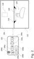
- FIG. 1 schematically illustrates, in a perspective view, a microscope arrangement 160 comprising a microscope 100 for microscopic examination of a sample 120, and a microscope parameter controller 140 according to an embodiment of the invention.
- Microscope 100 comprises a sample incubation system 110.
- the controller 140 represented by PC 146 is connected with the user interface 148 such that a user may control microscope operation through user interface 148 via microscope parameter controller 140 which is connected to microscope 100.
- the functionality of the PC 146 can also be performed by one or more processors as described above, and/or the controller 140 can be integrated into the microscope housing 102 and thus be part of the microscope 100.
- the user interface 148 can, for example, also comprise a touchscreen for receiving user input.
- Sample 120 can be placed onto microscope stage 116.
- Microscope housing 102 encloses an illumination optics 118, the microscope stage 116 and an imaging optics 124.
- An integrated sample chamber 106 is located within the microscope housing 102 and formed by a separated housing section 104 within said microscope housing 102.
- the housing 102 comprises a hinged lid 109, which provides, in its opened state, direct access to the microscope stage 116 for placing, removing and/or manipulating the sample 120 in the sample chamber 106.
- the embodiment shown in Figure 1 is an inverse transmitted-light microscope 100 where the transmitted-light illumination optics 118 is arranged within the housing section 104, while the imaging optics 124 is located below the microscope stage 116 in another housing section, forming an imaging optics chamber 122.
- the imaging optics 124 typically includes a microscope objective and an image detector as the main components.
- the image detector usually comprises a camera, which generates microscopic images, which are typically displayed on a display screen, like the display screen of user interface 148 or on a separate part of this display or on another display (not shown). It is noted again that embodiments of the present invention may also refer to other types of microscopes like upright microscopes, incident-light microscopes, confocal microscopes, widefield microscopes etc.
- microscope 100 further comprises a sample incubation system 110.
- sample incubation system 110 is connected to the backside of microscope housing 102.
- the housing section 104 comprises an opening 114 (in this embodiment two openings 114) for receiving a conduit 108, through which incubation atmosphere can be introduced into the sample chamber 106.
- environmental conditions in the sample chamber 106 can be controlled by the sample incubation system 110 connected to the sample chamber 106 ("sample chamber incubation").
- Incubation atmosphere can be introduced through at least one of the conduits 114 into the sample chamber 106. Depending on an existing leakage of the sample chamber 106, a part of the incubation atmosphere is allowed to escape the sample chamber 106. On the other hand, a part of the incubation atmosphere can also be withdrawn from the sample chamber 106 e.g. via another one of conduits 114.
- Suitable incubation atmospheres comprise, e.g., air with a predefined content of H 2 O (water or water vapour, relative humidity) and a predefined content of CO 2 (carbon dioxide). It may also be desirable to conduct hypoxia experiments with a deficiency of oxygen in the atmosphere.
- H 2 O water or water vapour, relative humidity
- CO 2 carbon dioxide
- incubation atmosphere parameters like temperature, humidity, carbon dioxide concentration, oxygen concentration, and other parameters like fan speed, and possibly further microscope parameters relating to imaging of a sample as explained above
- target setpoints for at least a part of said parameters can be set by a user of the microscope 100, other parameters may be predefined or even fixedly predetermined.
- sensors in or at at least one of the conduits 108, the sample chamber 106 and/or the microscope stage 116 close to the sample 120.
- an atmosphere control for the imaging optics chamber 122 may be provided. Such an atmosphere control may also be operated by the microscope parameter controller 140.
- microscope parameter controller 140 is configured to control the operation of the sample incubation system 110.
- the microscope parameter controller is connected to a sample incubation controller 112, which is controlled by microscope parameter controller 140 and provided for implementing and monitoring/checking the sample incubation atmosphere parameters as set by the microscope parameter controller 140.
- an atmosphere regulation module 113 which includes the above-mentioned sensors for detecting actual values of incubation atmosphere parameters and/or for receiving such sensor signals.
- Atmosphere regulation module 113 is connected to the sample incubation controller 112 of the sample incubation system 110. In that way, a feedback control can be implemented to set a group of sample incubation atmosphere parameters to the desired setpoints.
- the sample incubation controller 112 can be part of or integrated into microscope parameter controller 140.
- stage top incubation may be realised by a stage top sample chamber 156 as indicated by dashed lines.
- a connection to an opening 114 and/or a conduit 108 can also be established in order to provide the respective incubation atmosphere into the smaller stage top sample chamber 156.
- the user can select which incubation mode to use, in this embodiment, either sample chamber incubation or stage top incubation.
- Figure 2 schematically illustrates the interrelation between the microscope parameter controller 140, namely the graphical user interface 142, and the sample 120 to be examined by the microscope 100 of Figure 1 .
- the embodiment of a graphical user interface 142 according to Figure 2 relates to a subset of possible microscope parameters as explained in detail above. Without loss of generality, in the following, mainly sample incubation atmosphere parameters are discussed. This discussion is valid for any other microscope parameters as mentioned above in an analogous manner.
- Graphical user interface 142 of the microscope parameter controller 140 displays various symbols 244a, 244b, and 244c for parameters, which are, at least in part, adjustable by corresponding widgets 246a, 246b, and 246c.
- 244a is a symbol for the temperature of the sample or of the sample incubation atmosphere
- 244b is a symbol for the relative humidity of the incubation atmosphere
- 244c is a symbol for the carbon dioxide (CO 2 ) concentration in the sample chamber 106.
- Said parameters may be set either by a user or may be predefined by the microscope parameter controller 140, optionally including the option of a user altering a predefined parameter.
- widgets are provided for receiving a user input for setting/adjusting the parameters, particularly for setting target setpoints for said parameters.
- Widget 246a receives a user input for rising or lowering a target setpoint for the temperature, for instance, via clicking on respective soft buttons.
- Widget 246b shows a (predefined) value of relative humidity, which value may be altered by user input as explained further below.
- Widget 246c provides the user the possibility of rising or lowering the target setpoint for the CO 2 concentration via clicking on respective soft buttons of widget 246c.
- the relative humidity may be automatically set by the microscope parameter controller 140 and the corresponding target setpoint may only be displayed for information purposes to a user via widget 246b.
- the graphical user interface 142 further displays a coloured symbol 244d, representing a (virtual) lamp. Such lamp may switch from red to green when the sample examination can start, for example, when all the target setpoints are reached or when at least a number of parameters have reached their target setpoints or when at least a predefined percentage (threshold) of a target setpoint has been reached. Examples will be explained in more detail further below.
- FIG. 2 illustrates the sample chamber 106 and the imaging optics chamber 122 in a very schematic way.
- illumination optics 118, the microscope stage 116, the sample 120, and the imaging optics 124 are shown.
- the imaging optics 124 by means of example, comprises a motorized (immersion) objective on a turret.
- stage top incubation of stage top chamber 156 or incubation of the imaging optics chamber 122 see also the explanations given above in connection with Figure 1 ).
- target setpoints of sample incubation atmosphere parameters namely temperature, CO 2 concentration and optionally relative humidity can be input by a user.
- the microscope parameter controller 140 with the support of the sample incubation controller 112 controls the sample incubation system 110 to generate and maintain the desired incubation atmosphere inside the sample chamber 106 as explained above in connection with Figure 1 .
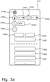
- Figure 3 schematically shows another embodiment of a graphical user interface 142 of a microscope parameter controller 140 configured for receiving user input ( Figure 3a ), said microscope parameter controller 140 being configured to track one or more user settings of microscope parameters and to determine at least one predefined setting of microscope parameters from one or more of the tracked user settings as shown in Figure 3b .
- Figure 3a shows an embodiment of a graphical user interface 142 comprising symbols 244a, 244b, 244c, and 244d and corresponding widgets 246a, 246b, and 246c as already described in connection with Figure 2 .
- the target setpoint of the temperature is set to 37° C
- the target setpoint of the CO 2 concentration is set to 5%
- the predefined target setpoint of relative humidity is 62%.
- this target setpoint can be changed by widget 346f, for example in order to reduce humidity.
- the user can select sample chamber incubation by widget 346d or stage top incubation by widget 346e.
- Symbol 344e signals whether sensor calibration is still ongoing or completed.
- widgets may be provided in graphical user interface 142 configured to receive user settings of other microscope parameters. For example, a user may select the kind of sample carrier by widget 346g, the kind of microscopic imaging mode by widget 346h, the fluorescence channel for observing a sample image by widget 346i, etc.
- the microscope parameter controller 140 of this embodiment is configured to register a user setting of microscope parameters represented by widgets 246a to 246c, and 346d to 346i. Such a registering may comprise storing the user setting of microscope parameters in a memory designated to this purpose of the microscope parameter controller 140, and keeping it e.g. together with a suitable time and/or probability indication, as explained above, even if the respective user has completed sample examination and, possibly, turned off the microscope parameter controller 140.
- the microscope parameter controller is further configured to determine at least one predefined setting of microscope parameters from the user-defined user setting(s) such that the graphical user interface 142 of the microscope parameter controller 140 may display such a predefined setting according to Figure 3b .
- the graphical user interface 142 provides a symbol 348 displaying the predefined setting of microscope parameters, which is, in this example, the very setting of Figure 3a relating to one or more, preferably all of widgets 246a to 246c, and 346d to 346i.
- the predefined setting of microscope parameters as represented by symbol 348 is provided to the user at the next usage of microscope 100 for sample examination.
- a widget 349 is provided for enabling the user to switch back to all settings shown in Figure 3a by e.g. clicking on widget 349.
- the microscope parameter controller 140 is further configured to select the predefined setting of microscope parameters as represented by widget 348 for starting a microscope operation applying the selected predefined setting of microscope parameters.
- the microscope parameter controller 140 automatically starts microscope 100 with microscope parameters as defined in Figure 3a in order to more quickly achieve the operating status for examining a sample, which is signalled by symbol 244d.
- a user may wish to change the predefined setting by selecting widget 349.
- displaying the predefined setting of microscope parameters in the form of symbol 348 to a user saves the user from again defining setpoints of microscope parameters as illustrated in Figure 3a . This saves considerable time for any user, particularly for an unexperienced user.
- a further timesaving is achieved by automatically starting the system immediately applying the predefined setting of microscope parameters.
- Another advantage of this embodiment of the invention is that a user can define the sample incubation atmosphere parameters together with other microscope imaging parameters by means of a single graphical user interface 142 combining the corresponding symbols and widgets.
- Embodiments of the present invention thus, in a particular example, allow a user to examine zebrafish in Petri dishes at 28°C and a predetermined humidity and CO 2 concentration initially in transmitted light (corresponding to a first predefined microscope parameter setting), and subsequently in confocal fluorescence microscope imaging (corresponding to a second predefined microscope parameter setting) using a microscope being able to provide the corresponding imaging modes, since the microscope parameter controller 140 is able of self-learning these two predominantly used microscope parameter settings.
- Figure 4 schematically shows an embodiment of a graphical user interface 142 at three different times of usage.
- Figure 4a shows the graphical user interface 142 at a first time of usage of microscope 100
- Figure 4b shows the graphical user interface 142 at another/second time of usage of microscope 100
- Figure 4c shows the graphical user interface 142 at a third time of usage.
- the graphical user interface 142 of Figures 4a and 4b essentially corresponds to the one shown in Figure 3a .
- Figure 3a discusses to the discussion of Figure 3a regarding symbols and widgets of the graphical user interface 142 of Figures 4a and 4b .
- the user at the first usage, has set the temperature to a setpoint of 28° C, the humidity to the standard value of 62% and the CO 2 concentration to 1% by operating widgets 246a to 246c accordingly. He/she has further selected a Petri dish as sample carrier.
- the user has adjusted the setting of the first usage, particularly by not accepting the predefined (previous) setting of microscope parameters and by inputting a different setting, namely a temperature setpoint of 30° C, a relative humidity of still 62%, and a CO 2 concentration of now 0%. Further, the user has selected a multiwell plate as sample carrier.
- the microscope parameter controller 140 registers the user settings as shown in Figure 4a and 4b , i.e. stores the relevant set of parameters, optionally including a time and/or probability indication for further use at another time of usage of microscope 100.
- the microscope parameter controller 140 determines at least one predefined setting of microscope parameters from the registered user settings at the first and the second time of usage. In this embodiment, both previous user-defined user settings are determined as the two predefined settings of microscope parameters, which are offered to the user at the third usage of the system.
- the two predefined settings of microscope parameters may also correspond to the two most frequently used user-defined parameter settings.
- Symbol 448a illustrates relevant parameters of the first predefined setting corresponding to the setting as shown in Figure 4a .
- Symbol 448b shows relevant parameters of the second predefined setting corresponding to the user setting as shown in Figure 4b .
- the microscope parameter controller 140 is further configured by means of widgets 449a and 449b to receive a user selection of one of the two predefined settings of microscope parameters for a microscope operation at the third usage by applying the selected predefined setting of microscope parameters to the operation of microscope 100.
- widget 449a the user may select the parameter setting of Figure 4a
- widget 449b the user may select the parameter setting of Figure 4b .
- another widget 449c is provided for returning to a menu where all parameter settings may be changed in order to create a third predefined parameter setting.
- a user identity may not be required for the embodiment according to Figures 4a to 4c . It may be as well that two different users input the parameter settings according to Figures 4a and 4b , while one of these users or even another third user is prompted to select or to change predefined settings as shown in Figure 4c .
- the microscope parameter controller 140 may be used to register user-defined user settings of microscopic parameters user-specifically for one or more users of the microscope 100.
- the user-specific tracking may be performed by the microscope parameter controller 140 by using, for instance, a user ID, which the user uses when logging on to the computer/PC 146 as shown in Figure 1 .
- a user ID may also be recognised through near-field communication (NFC) by communicating with a user's ID tag or smartphone etc.
- operation of microscope 100 may be set up to user-specifically determine one or more predefined settings of microscope parameters in dependence of the respective user of the microscope 100.
- the at least one predefined setting of microscopic parameters is determined as the previous user setting ( Figure 3 ) or as the previous and the penultimate user settings ( Figure 4 ).
- the microscope parameter controller 140 may determine a predefined setting of microscope parameters as the most frequently used user setting (through a number of users or regarding a specific user).
- the microscope parameter controller may determine the at least one predefined setting of microscope parameters as the second, third or, more generally, n th , n>3, most frequently used user setting. Especially if all users are taken into account, it may make sense to determine the three most frequently used user settings as the predefined parameter settings displayed on the graphical user interface 142.
- the predefined setting of microscope parameters (or one of the predefined settings of microscope parameters) comprises mean values of one or more respective microscope parameters of previous user settings. An automated system start using such a predefined parameter setting can save time to reach the desired setpoints.
- Figure 5 shows relevant parts of graphical user interfaces 142 displaying predefined settings of microscope parameters.
- Figure 5a shows symbol 548a representing a predefined setting of microscope parameters as personal settings of a first user. This personal setting may be the most frequent setting of this user or simply the previous setting by this user.
- Figure 5b shows symbols 548b and 548c representing two different predefined settings of microscope parameters as an example of personal settings by another second user.
- the predefined parameter settings may include a most frequent user setting and/or a previous user setting. It is noted that other possibilities of determining a predefined parameter setting were discussed above.
- Figure 5c shows symbols 548d, 548e, and 548f representing three different predefined parameter settings as an example of all user frequent settings.
- the respective predefined parameter settings may represent the three most frequently used user settings throughout the users. Other possibilities of determining predefined parameter settings have been discussed above.
- Some or all of the method steps may be executed by (or using) a hardware apparatus, like for example, a processor, a microprocessor, a programmable computer or an electronic circuit. In some embodiments, some one or more of the most important method steps may be executed by such an apparatus.
- embodiments of the invention can be implemented in hardware or in software.
- the implementation can be performed using a non-transitory storage medium such as a digital storage medium, for example a floppy disc, a DVD, a Blu-Ray, a CD, a ROM, a PROM, and EPROM, an EEPROM or a FLASH memory, having electronically readable control signals stored thereon, which cooperate (or are capable of cooperating) with a programmable computer system such that the respective method is performed. Therefore, the digital storage medium may be computer readable.
- Some embodiments according to the invention comprise a data carrier having electronically readable control signals, which are capable of cooperating with a programmable computer system, such that one of the methods described herein is performed.
- embodiments of the present invention can be implemented as a computer program product with a program code, the program code being operative for performing one of the methods when the computer program product runs on a computer.
- the program code may, for example, be stored on a machine readable carrier.
- inventions comprise the computer program for performing one of the methods described herein, stored on a machine readable carrier.
- an embodiment of the present invention is, therefore, a computer program having a program code for performing one of the methods described herein, when the computer program runs on a computer.
- a further embodiment of the present invention is, therefore, a storage medium (or a data carrier, or a computer-readable medium) comprising, stored thereon, the computer program for performing one of the methods described herein when it is performed by a processor.
- the data carrier, the digital storage medium or the recorded medium are typically tangible and/or non-transitionary.
- a further embodiment of the present invention is an apparatus as described herein comprising a processor and the storage medium.
- a further embodiment of the invention is, therefore, a data stream or a sequence of signals representing the computer program for performing one of the methods described herein.
- the data stream or the sequence of signals may, for example, be configured to be transferred via a data communication connection, for example, via the internet
- a further embodiment comprises a processing means, for example, a computer or a programmable logic device, configured to, or adapted to, perform one of the methods described herein.
- a processing means for example, a computer or a programmable logic device, configured to, or adapted to, perform one of the methods described herein.
- a further embodiment comprises a computer having installed thereon the computer program for performing one of the methods described herein.
- a further embodiment according to the invention comprises an apparatus or a system configured to transfer (for example, electronically or optically) a computer program for performing one of the methods described herein to a receiver.
- the receiver may, for example, be a computer, a mobile device, a memory device or the like.
- the apparatus or system may e.g. comprise a file server for transferring the computer program to the receiver.
- a programmable logic device for example, a field programmable gate array
- a field programmable gate array may cooperate with a microprocessor in order to perform one of the methods described herein.
- the methods are preferably performed by any hardware apparatus.
Abstract
Description
- The present invention relates to a microscope parameter controller for controlling microscope parameters, and to a microscope arrangement including such a microscope parameter controller, and to a method for controlling microscope parameters, more particularly, to the field of controlling microscope parameters for handling, maintaining and/or imaging a sample before and/or during microscopic examination.
- Especially in the field of microscopic examination of living samples like cells, it is of great interest to keep the sample as long as possible under favourable and stress-free environmental conditions. To this end, incubators can be used for generating an incubation atmosphere or microclimate adapted to the sample to be examined. Microscopic examination of a sample, particularly a living sample, typically involves handling the sample, maintaining/preserving the sample during and before examination and/or imaging the sample.
- Incubators can be distinguished in stage top incubators, on the one hand, and cage incubators, on the other hand. Cage incubators are, typically, mounted to a standard microscope and comprise a large climatic chamber covering the main parts of the microscope, such as the objective revolver, the microscope stage including the sample carrier and an illumination condenser, such that a large volume needs to be incubated. On the other hand, a stage top incubator provides a small volume to be incubated as the stage top incubator only encloses the sample itself and is placed onto the microscope stage. While a cage incubator entails relatively high energy and gas consumption to maintain the required incubation atmosphere, a stage top incubator provides a small closed incubated space including connected supply conduits for supplying the desired incubation atmosphere.
- When examining a sample, particularly using such a microscope and incubator, various microscope parameters have to be set automatically and/or by a user in order to be able to properly handle and maintain a sample before and during examination and to choose a suited imaging mode for imaging the sample. To this end, the user needs to have a good understanding of the sample properties, on the one hand, and of the technical parameters of the microscope including the incubator.
- In view of the situation described above, there is a need for an improved control of microscope parameters for handling, maintaining and/or imaging a sample before and during examination by a microscope. According to embodiments of the invention, a microscope parameter controller, a microscope arrangement including such a microscope controller, a method for controlling microscope parameters, and a computer program for performing such a method according to the independent claims are provided. Embodiments are the subject matter of the dependent claims and of the description as follows.
- Embodiments of the invention relate to a microscope parameter controller for controlling microscope parameters for handling, maintaining and/or imaging a sample, said microscope parameter controller being configured to determine at least one predefined setting of microscope parameters from one or more of user-defined user settings of microscope parameters.
- "Handling" a sample comprises e.g. placing a sample onto a microscope stage of a microscope, removing the sample from the stage, and/or manipulating the sample during or before examination. "Maintaining" a sample comprises maintaining or preserving a sample before and/or during examination, particularly during imaging of the sample by means of the microscope and its accessories like a sample atmosphere incubator. "Imaging" a sample comprises illuminating the sample and imaging the sample by means of imaging optics of the microscope. Possible imaging methods comprise e.g. widefield, lightsheet and confocal microscopy including fluorescence microscopy.
- "Microscope parameters for handling, maintaining and/or imaging a sample" comprise, especially in case of an incubated sample, sample incubation atmosphere parameters and microscope imaging parameters. Such parameters are, for instance, the temperature at the sample and/or of the incubation atmosphere, the relative humidity and a CO2 and/or N2 content of the incubation atmosphere, the incubation mode, like cage or stage top incubation or integrated sample chamber incubation as explained below, the kind of sample carrier, like Petri dish, multiwell plate, etc. Further, the imaging mode, like widefield, lightsheet or confocal microscopy, and in case of fluorescence microscopy, excitation wavelengths and emission or observation wavelengths. Further microscope parameters may be associated with illumination intensity, magnification of microscope objective and any other parameters influencing imaging, maintaining or manipulation of a sample.
- "Determining at least one predefined setting of microscope parameters from one or more of user-defined user settings of microscope parameters" may generally comprise registering/remembering all or at least a part of user-defined user settings of microscope parameters, which user-defined user settings may be microscope parameter settings previously input by a user and/or otherwise used by a user. A microscope parameter setting input and/or otherwise used by a user comprises microscope parameters, which are input by a user and/or selected and/or accepted from a number of predefined microscope parameters and/or accepted microscope parameters from factory defaults (recommendations) such as e.g. certain temperature settings for certain specific samples types. Such a registering may be performed by storing the microscope parameter settings as input or otherwise used by a user in a memory/storage e.g. together with a time indication of the time of input/use of the respective user setting, and, optionally, together with a user identification (ID). The time indication may comprise a clock time and/or a sequence indication like "previous", "penultimate" etc. or "first", "second", "third" etc. usage of input/used user setting. It is noted that it is not necessary to store each and every user-defined user setting input or used by a user. In an embodiment, the microscope parameter controller is a learning system, which adapts to a user, either user-specific or in relation to a plurality of users, such that e.g. the most frequently used user setting or e.g. the two most frequently used user settings are stored while other rarely or only once used user settings are discarded. Thus, alternatively or additionally to a time indication, a probability indication may be used for designating a user setting as the most, second most etc. frequently used user setting. In a simple embodiment, only the most frequently used user setting is stored. The microscope parameter controller is further configured to process said one or more user-defined user settings as will be explained in further detail below, to determine at least one predefined setting of microscope parameters, i.e. at least one microscope parameter setting defined by the microscope parameter controller, which microscope parameter setting thus constitutes, from a user perspective, a predefined microscope parameter setting. This one or more predefined microscope parameter setting may be suggested to a user at a next time of using the microscope and/or may be used to immediately start a microscope operation at a next time of using the microscope, as will be explained below.
- In an embodiment, the microscope parameter controller is further configured to select one of the at least one predefined setting of microscope parameters for starting a microscope operation applying the selected predefined setting of microscope parameters. In other words, the microscope parameter controller automatically starts operation of the microscope with a selected predefined microscope parameter setting (e.g. fulfilling minimal requirements of microscope operation or adapting the microscope and its accessories to the needs of a specific sample type or organism) in order to more quickly achieve the operating status for examining and/or for maintaining a sample. Still, while the system already starts operation in order to reach the selected predefined setting of microscope parameters, a user may be allowed to change the selected predefined setting.
- In an embodiment, the microscope parameter controller is further configured to receive a user selection of one of the at least one predefined setting of microscope parameters for a microscope operation applying the user-selected predefined setting of microscope parameters. As explained above, such a user-selected predefined setting of microscope parameters can also be regarded a user-defined user setting of microscope parameters and registered accordingly, e.g. regarding a frequency of use.
- In an embodiment, the microscope parameter controller is further configured to determine at least one predefined setting of microscopic parameters user-specifically for one or more users of a microscope. This increase safety of operation and enables user-specific traceability of use.
- In an embodiment, the at least one predefined setting of microscope parameters is determined in dependence of the current user of the microscope. In other words, the one or more predefined settings of microscope parameters are user-specifically proposed to a user.
- In an embodiment, the at least one predefined setting of microscope parameters is determined as at least one of: one or more of the previous user settings; the most frequently used user setting; the second, third or nth, n>3, most frequently used user setting; and a setting comprising one or more mean values of one or more respective microscope parameters of previous user settings. This saves considerable time in defining a microscope parameter setting, especially in case of recurrent identical or similar settings.
- In an embodiment, the microscope parameter controller is configured to control sample incubation atmosphere parameters of a sample incubation atmosphere provided for handling, maintaining and/or imaging of an incubated sample. In this embodiment, the microscope parameter controller can be regarded a "sample incubation atmosphere parameter controller". This and the following embodiments and their advantages will be described in further detail below.
- In an embodiment, the sample incubation atmosphere parameters comprise at least one of a temperature, a carbon dioxide concentration, a humidity content of the sample incubation atmosphere, and a kind of sample carrier used for carrying the sample.
- In an embodiment, the microscope parameter controller is configured to render a graphical user interface providing at least one symbol configured to display the at least one predefined setting of microscope parameters and/or providing at least one widget configured to receive a user input for setting at least one microscope parameter.
- The term "widget" shall, in the understanding used herein, refer to any element of interaction rendered as a part of a graphical user interface including, but not limited to, elements configured for selection and for the display of elements or collections such as buttons (including radio buttons, check boxes, toggle switches, toggle buttons, split buttons, cycle buttons), sliders, list boxes, spinners, drop-down lists, menus (including context menus and pie menus), menu bars, tool bars (including ribbons), combo boxes, icons, tree views, grid views, elements configured for navigation such as links, tabs and scrollbars, elements for textual input such as text and combo boxes, elements for output of information such as labels, tool tips, help balloons, status bars, progress bars and information bars, and containers such as (modal) windows, dialog boxes, palettes, frames and canvas elements.
- The present invention also relates to a microscope arrangement comprising a microscope and the microscope parameter controller according to embodiments of the present invention for controlling microscope parameters of the microscope.
- In an embodiment, the microscope comprises a sample incubation system for providing a sample incubation atmosphere for handling, maintaining and/or imaging of an incubated sample, wherein the microscope parameter controller is configured to control sample incubation atmosphere parameters of a sample incubation atmosphere, and wherein the microscope parameter controller is preferably further configured for controlling other microscope parameters e.g. for a microscope imaging operation.
- The present invention also relates to a method for controlling microscope parameters for handling, maintaining and/or imaging a sample by means of a microscope, said method comprising the step of determining at least one predefined setting of microscope parameters from one or more user-defined user settings of microscope parameters.
- In an embodiment, said method comprises the further step of selecting one of the at least one predefined setting of microscope parameters for starting a microscope operation applying the selected predefined setting of microscope parameters (e.g. based on type of organism analysed).
- In another embodiment, the method comprises the further step of offering a user of the microscope to choose one of the at least one predefined setting of microscope parameters for a microscope operation applying the user-selected predefined setting of microscope parameters. Such a user-selected predefined setting of microscope parameters can also be regarded a user-defined user setting of microscope parameters.
- In an embodiment, the microscope parameters are or comprise sample incubation atmosphere parameters, as already discussed above, of a sample incubation atmosphere provided for handling, maintaining and/or imaging of an incubated sample.
- The invention also relates to a computer program with a program code for performing the method according to embodiments of the invention as described above, when the computer program is run on a processor, particularly on a microscope parameter controller according to embodiments of the present invention as described above.
- Short description of the figures
- Figure 1
- schematically shows a microscope having a sample incubation system and a microscope parameter controller;
- Figure 2
- illustrates a graphical user interface of the microscope parameter controller and its interrelation with a sample examined by the microscope;
- Figure 3
- shows an embodiment of a graphical user interface of a microscope parameter controller for receiving user input for defining a user setting of microscope parameters (
Figure 3a ), and an embodiment of a corresponding graphical user interface displaying a predefined microscope parameter setting (Figure 3b ); - Figure 4
- illustrates a graphical user interface of a microscope parameter controller configured to receive user input for defining user settings of microscope parameters at a first usage (
Figure 4a ), at a second usage (Figure 4b ), and the corresponding graphical user interface displaying predefined settings of microscope parameters at a third usage (Figure 4c ); and - Figure 5
- illustrates a part of a graphical user interface displaying a predefined setting of microscope parameters from a first user (
Figure 5a ), from a second user (Figure 5b ), and for all users (Figure 5c ). - In the following, the figures will be described comprehensively, same reference signs relating to same or at least functionally same elements. The figures and their description are to be understood as illustrating, without loss of generality, examples of a microscope parameter controller, a microscope, and a method for controlling microscope parameters according to the present invention.
- An embodiment of a microscope parameter controller is shown in
Figure 1 and denoted by 140. In this embodiment, themicroscope parameter controller 140 is represented by aPC 146, and renders auser interface 148; theuser interface 148 comprises, e.g., a display or display screen for displaying a graphical user interface 142 (which will be further described in the figures below), and a keyboard and a computer mouse for providing user interaction. Themicroscope parameter controller 140 is configured to control microscope parameters for handling, maintaining and/or imaging asample 120. "Handling" asample 120 comprises placing asample 120 onto amicroscope stage 116 of amicroscope 100 as shown inFigure 1 , removing thesample 120 from thestage 116, and manipulating thesample 120 during examination. "Maintaining" asample 120 comprises maintaining or preserving asample 120 before and/or during examination, particularly during imaging of thesample 120 by means of themicroscope 100. As already mentioned at the outset, examination of living cells, for instance, require maintaining a quite tight window of sample incubation atmosphere parameters as well as of other parameters like illumination intensity in order to avoid damaging/bleaching of the sample. "Imaging" a sample comprises illuminating thesample 120 and imaging the sample by means of imaging optics. Possible imaging methods comprise e.g. widefield, lightsheet and confocal microscopy including fluorescence microscopy. - "Microscope parameters for handling, maintaining and/or imaging a sample" thus particularly comprise, in case of an incubated sample, sample incubation atmosphere parameters and microscope imaging parameters. Such parameters are, for instance, the temperature at the sample and/or of the incubation atmosphere, the relative humidity and a CO2 and/or N2 content of the incubation atmosphere, the incubation mode, like cage or stage top incubation or integrated sample chamber incubation as explained below, the kind of sample carrier, like Petri dish, multiwell plate, etc. Further, the imaging mode, like widefield, lightsheet or confocal microscopy, and in case of fluorescence microscopy, excitation wavelengths and emission or observation wavelengths. Further microscope parameters may be associated with illumination intensity, magnification of microscope objective and any other parameters influencing imaging of a sample.
- Through its
user interface 148, themicroscope parameter controller 140 is configured to receive user input setting microscope parameters for handling, maintaining and/or imaging thesample 120. "Determining at least one predefined setting of microscope parameters from one or more of user-defined user settings of microscope parameters" may generally comprise registering/remembering all or at least a part of user-defined user settings of microscope parameters, which user-defined user settings may be microscope parameter settings previously input by a user and/or otherwise used by a user, e.g. by selecting a predefined microscope parameter setting as suggested by the system. Such a registering may be performed by storing the microscope parameter settings as input or otherwise used by a user in a cache, buffer or other memory/storage e.g. together with a time indication of the time of input/use of the respective user setting, and, optionally, together with a user identification (ID). The time indication may comprise a clock time and/or a sequence indication like "previous", "penultimate" etc. or "first", "second", "third" etc. input/used user setting. It is noted that it is not necessary to store each and every user setting input or used by a user. In an embodiment, the microscope parameter controller is a learning system, which adapts to a user (or to the users) such that e.g. the most frequently used user setting or e.g. the two most frequently used user settings are stored while other rarely or only once used user settings are discarded. Thus, alternatively or additionally to a time indication, a probability indication may be used for designating a user setting as the most, second most etc. frequently used user setting. In a simple embodiment, only the most frequently used user setting is stored. Themicroscope parameter controller 140 is further configured to determine at least one predefined setting of microscope parameters from one or more of the tracked user-defined user settings as will be explained further below. - The
controller 140 may include one or more processors. The processor(s) can be of any type and can be provided in any number and at any position and in any component of themicroscope 100. As used herein, the term processor(s) may refer to any type of computational circuit, such as, but not limited to, a microprocessor, a microcontroller, a complex instruction set computing (CISC) microprocessor, a reduced instruction set computing (RISC) microprocessor, a very long instruction word (VLIW) microprocessor, a graphics processor, a digital signal processor (DSP), a multiple core processor, a field programmable gate array unit (FPGA). Other types of processing circuits that may be included in thecontroller 140 may be a custom circuit, an application-specific integrated circuit (ASIC), or the like, such as, for example, one or more circuits (such as a communication circuit) for use in wireless devices like mobile telephones, tablet computers, laptop computers, two-way radios, and similar electronic systems. - The memory/storage of the
controller 140 may comprise one or more memory elements suitable to the particular application, such as a main memory in the form of random access memory (RAM), one or more hard drives, and/or one or more drives that handle removable media such as compact disks (CD), flash memory cards, digital video disk (DVD), and the like. - Before discussing the way of determining at least one predefined setting of microscope parameters by the
microscope parameter controller 140 in more detail, the embodiment ofmicroscope 100 shown inFigure 1 is now described in more detail. -
Figure 1 schematically illustrates, in a perspective view, amicroscope arrangement 160 comprising amicroscope 100 for microscopic examination of asample 120, and amicroscope parameter controller 140 according to an embodiment of the invention.Microscope 100 comprises asample incubation system 110. Thecontroller 140 represented byPC 146 is connected with theuser interface 148 such that a user may control microscope operation throughuser interface 148 viamicroscope parameter controller 140 which is connected tomicroscope 100. Note that the functionality of thePC 146 can also be performed by one or more processors as described above, and/or thecontroller 140 can be integrated into themicroscope housing 102 and thus be part of themicroscope 100. Theuser interface 148 can, for example, also comprise a touchscreen for receiving user input. -
Sample 120 can be placed ontomicroscope stage 116.Microscope housing 102 encloses anillumination optics 118, themicroscope stage 116 and animaging optics 124. Anintegrated sample chamber 106 is located within themicroscope housing 102 and formed by a separatedhousing section 104 within saidmicroscope housing 102. Thehousing 102 comprises a hingedlid 109, which provides, in its opened state, direct access to themicroscope stage 116 for placing, removing and/or manipulating thesample 120 in thesample chamber 106. - The embodiment shown in
Figure 1 is an inverse transmitted-light microscope 100 where the transmitted-light illumination optics 118 is arranged within thehousing section 104, while theimaging optics 124 is located below themicroscope stage 116 in another housing section, forming animaging optics chamber 122. Theimaging optics 124 typically includes a microscope objective and an image detector as the main components. The image detector usually comprises a camera, which generates microscopic images, which are typically displayed on a display screen, like the display screen ofuser interface 148 or on a separate part of this display or on another display (not shown). It is noted again that embodiments of the present invention may also refer to other types of microscopes like upright microscopes, incident-light microscopes, confocal microscopes, widefield microscopes etc. - The construction of the
microscope housing section 104 allows - after closing the lid 109 - to form adedicated sample chamber 106, which constitutes a closed space, which can be incubated such thatsample 120, like living cells, can be kept under favourable and stress-free environmental conditions. To this end,microscope 100 further comprises asample incubation system 110. In the embodiment shown inFigure 1 ,sample incubation system 110 is connected to the backside ofmicroscope housing 102. Thehousing section 104 comprises an opening 114 (in this embodiment two openings 114) for receiving aconduit 108, through which incubation atmosphere can be introduced into thesample chamber 106. Thus, environmental conditions in thesample chamber 106 can be controlled by thesample incubation system 110 connected to the sample chamber 106 ("sample chamber incubation"). Incubation atmosphere can be introduced through at least one of theconduits 114 into thesample chamber 106. Depending on an existing leakage of thesample chamber 106, a part of the incubation atmosphere is allowed to escape thesample chamber 106. On the other hand, a part of the incubation atmosphere can also be withdrawn from thesample chamber 106 e.g. via another one ofconduits 114. - Suitable incubation atmospheres comprise, e.g., air with a predefined content of H2O (water or water vapour, relative humidity) and a predefined content of CO2 (carbon dioxide). It may also be desirable to conduct hypoxia experiments with a deficiency of oxygen in the atmosphere. For further details about specific parameters and suitable or preferred ranges of sample incubation atmosphere parameters, please refer to the description of the following figures.
- Note that controlling the relevant parameters (incubation atmosphere parameters like temperature, humidity, carbon dioxide concentration, oxygen concentration, and other parameters like fan speed, and possibly further microscope parameters relating to imaging of a sample as explained above), in this embodiment, will be performed in an automated manner by means of the
microscope parameter controller 140. To this end, target setpoints for at least a part of said parameters can be set by a user of themicroscope 100, other parameters may be predefined or even fixedly predetermined. In order to control said incubation atmosphere parameters, it is preferred to arrange sensors in or at at least one of theconduits 108, thesample chamber 106 and/or themicroscope stage 116 close to thesample 120. - For increasing the lifespan of the
imaging optics 124, and, particularly, in case of using immersion objectives, an atmosphere control for theimaging optics chamber 122 may be provided. Such an atmosphere control may also be operated by themicroscope parameter controller 140. - As already explained above,
microscope parameter controller 140 is configured to control the operation of thesample incubation system 110. To this end, in this embodiment, the microscope parameter controller is connected to asample incubation controller 112, which is controlled bymicroscope parameter controller 140 and provided for implementing and monitoring/checking the sample incubation atmosphere parameters as set by themicroscope parameter controller 140. At the backside of thehousing section 104, there is anatmosphere regulation module 113, which includes the above-mentioned sensors for detecting actual values of incubation atmosphere parameters and/or for receiving such sensor signals.Atmosphere regulation module 113 is connected to thesample incubation controller 112 of thesample incubation system 110. In that way, a feedback control can be implemented to set a group of sample incubation atmosphere parameters to the desired setpoints. It is noted that, in other embodiments, thesample incubation controller 112 can be part of or integrated intomicroscope parameter controller 140. - Apart from the above-described sample chamber incubation, another incubation mode, namely a stage top incubation may be realised by a stage
top sample chamber 156 as indicated by dashed lines. A connection to anopening 114 and/or aconduit 108 can also be established in order to provide the respective incubation atmosphere into the smaller stagetop sample chamber 156. As explained further below, the user can select which incubation mode to use, in this embodiment, either sample chamber incubation or stage top incubation. -
Figure 2 schematically illustrates the interrelation between themicroscope parameter controller 140, namely thegraphical user interface 142, and thesample 120 to be examined by themicroscope 100 ofFigure 1 . The embodiment of agraphical user interface 142 according toFigure 2 relates to a subset of possible microscope parameters as explained in detail above. Without loss of generality, in the following, mainly sample incubation atmosphere parameters are discussed. This discussion is valid for any other microscope parameters as mentioned above in an analogous manner. -
Graphical user interface 142 of themicroscope parameter controller 140 displaysvarious symbols widgets sample chamber 106. Said parameters may be set either by a user or may be predefined by themicroscope parameter controller 140, optionally including the option of a user altering a predefined parameter. In the embodiment shown inFigure 2 , widgets are provided for receiving a user input for setting/adjusting the parameters, particularly for setting target setpoints for said parameters. Note that other means of receiving a user input for setting/adjusting parameters are possible.Widget 246a receives a user input for rising or lowering a target setpoint for the temperature, for instance, via clicking on respective soft buttons.Widget 246b shows a (predefined) value of relative humidity, which value may be altered by user input as explained further below.Widget 246c provides the user the possibility of rising or lowering the target setpoint for the CO2 concentration via clicking on respective soft buttons ofwidget 246c. It is noted that it is not necessary for all incubation atmosphere parameters to be changeable by a user; for instance, the relative humidity may be automatically set by themicroscope parameter controller 140 and the corresponding target setpoint may only be displayed for information purposes to a user viawidget 246b. Thegraphical user interface 142 further displays acoloured symbol 244d, representing a (virtual) lamp. Such lamp may switch from red to green when the sample examination can start, for example, when all the target setpoints are reached or when at least a number of parameters have reached their target setpoints or when at least a predefined percentage (threshold) of a target setpoint has been reached. Examples will be explained in more detail further below. - The right side of
Figure 2 illustrates thesample chamber 106 and theimaging optics chamber 122 in a very schematic way. In particular,illumination optics 118, themicroscope stage 116, thesample 120, and theimaging optics 124 are shown. Note that theimaging optics 124, by means of example, comprises a motorized (immersion) objective on a turret. In this and the following embodiments, only a sample chamber incubation ofsample chamber 106 is discussed. The discussion is also valid for other incubation modes, like stage top incubation of stagetop chamber 156 or incubation of the imaging optics chamber 122 (see also the explanations given above in connection withFigure 1 ). - By user input via
widgets microscope parameter controller 140 with the support of thesample incubation controller 112 controls thesample incubation system 110 to generate and maintain the desired incubation atmosphere inside thesample chamber 106 as explained above in connection withFigure 1 . -
Figure 3 schematically shows another embodiment of agraphical user interface 142 of amicroscope parameter controller 140 configured for receiving user input (Figure 3a ), saidmicroscope parameter controller 140 being configured to track one or more user settings of microscope parameters and to determine at least one predefined setting of microscope parameters from one or more of the tracked user settings as shown inFigure 3b . -
Figure 3a shows an embodiment of agraphical user interface 142 comprisingsymbols corresponding widgets Figure 2 . By user input, the target setpoint of the temperature is set to 37° C, the target setpoint of the CO2 concentration is set to 5% and the predefined target setpoint of relative humidity is 62%. In this embodiment, this target setpoint can be changed bywidget 346f, for example in order to reduce humidity. Further, the user can select sample chamber incubation bywidget 346d or stage top incubation bywidget 346e.Symbol 344e signals whether sensor calibration is still ongoing or completed. - Other widgets may be provided in
graphical user interface 142 configured to receive user settings of other microscope parameters. For example, a user may select the kind of sample carrier bywidget 346g, the kind of microscopic imaging mode bywidget 346h, the fluorescence channel for observing a sample image bywidget 346i, etc. - The
microscope parameter controller 140 of this embodiment is configured to register a user setting of microscope parameters represented bywidgets 246a to 246c, and 346d to 346i. Such a registering may comprise storing the user setting of microscope parameters in a memory designated to this purpose of themicroscope parameter controller 140, and keeping it e.g. together with a suitable time and/or probability indication, as explained above, even if the respective user has completed sample examination and, possibly, turned off themicroscope parameter controller 140. The microscope parameter controller is further configured to determine at least one predefined setting of microscope parameters from the user-defined user setting(s) such that thegraphical user interface 142 of themicroscope parameter controller 140 may display such a predefined setting according toFigure 3b . - As shown in
Figure 3b , thegraphical user interface 142 provides asymbol 348 displaying the predefined setting of microscope parameters, which is, in this example, the very setting ofFigure 3a relating to one or more, preferably all ofwidgets 246a to 246c, and 346d to 346i. The predefined setting of microscope parameters as represented bysymbol 348 is provided to the user at the next usage ofmicroscope 100 for sample examination. For user flexibility, awidget 349 is provided for enabling the user to switch back to all settings shown inFigure 3a by e.g. clicking onwidget 349. - In an embodiment, the
microscope parameter controller 140 is further configured to select the predefined setting of microscope parameters as represented bywidget 348 for starting a microscope operation applying the selected predefined setting of microscope parameters. In other words, themicroscope parameter controller 140 automatically startsmicroscope 100 with microscope parameters as defined inFigure 3a in order to more quickly achieve the operating status for examining a sample, which is signalled bysymbol 244d. Still, while the system already starts operation in order to reach the predefined setting of microscope parameters, a user may wish to change the predefined setting by selectingwidget 349. - The inventors found that a specific user, and sometimes even a plurality of users using the
same microscope 100, typically chooses the same or at least essentially the same microscope parameters, at least when examining the same kind of sample. Thus, displaying the predefined setting of microscope parameters in the form ofsymbol 348 to a user saves the user from again defining setpoints of microscope parameters as illustrated inFigure 3a . This saves considerable time for any user, particularly for an unexperienced user. A further timesaving is achieved by automatically starting the system immediately applying the predefined setting of microscope parameters. Another advantage of this embodiment of the invention is that a user can define the sample incubation atmosphere parameters together with other microscope imaging parameters by means of a singlegraphical user interface 142 combining the corresponding symbols and widgets. - Embodiments of the present invention thus, in a particular example, allow a user to examine zebrafish in Petri dishes at 28°C and a predetermined humidity and CO2 concentration initially in transmitted light (corresponding to a first predefined microscope parameter setting), and subsequently in confocal fluorescence microscope imaging (corresponding to a second predefined microscope parameter setting) using a microscope being able to provide the corresponding imaging modes, since the
microscope parameter controller 140 is able of self-learning these two predominantly used microscope parameter settings. -
Figure 4 schematically shows an embodiment of agraphical user interface 142 at three different times of usage.Figure 4a shows thegraphical user interface 142 at a first time of usage ofmicroscope 100,Figure 4b shows thegraphical user interface 142 at another/second time of usage ofmicroscope 100, andFigure 4c shows thegraphical user interface 142 at a third time of usage. Thegraphical user interface 142 ofFigures 4a and4b essentially corresponds to the one shown inFigure 3a . Thus, reference is made to the discussion ofFigure 3a regarding symbols and widgets of thegraphical user interface 142 ofFigures 4a and4b . As can be seen fromFigure 4a , the user, at the first usage, has set the temperature to a setpoint of 28° C, the humidity to the standard value of 62% and the CO2 concentration to 1% by operatingwidgets 246a to 246c accordingly. He/she has further selected a Petri dish as sample carrier. At the second usage, as shown inFigure 4b , the user has adjusted the setting of the first usage, particularly by not accepting the predefined (previous) setting of microscope parameters and by inputting a different setting, namely a temperature setpoint of 30° C, a relative humidity of still 62%, and a CO2 concentration of now 0%. Further, the user has selected a multiwell plate as sample carrier. Themicroscope parameter controller 140 registers the user settings as shown inFigure 4a and4b , i.e. stores the relevant set of parameters, optionally including a time and/or probability indication for further use at another time of usage ofmicroscope 100. - This situation is illustrated by
Figure 4c . Themicroscope parameter controller 140 determines at least one predefined setting of microscope parameters from the registered user settings at the first and the second time of usage. In this embodiment, both previous user-defined user settings are determined as the two predefined settings of microscope parameters, which are offered to the user at the third usage of the system. The two predefined settings of microscope parameters may also correspond to the two most frequently used user-defined parameter settings.Symbol 448a illustrates relevant parameters of the first predefined setting corresponding to the setting as shown inFigure 4a .Symbol 448b shows relevant parameters of the second predefined setting corresponding to the user setting as shown inFigure 4b . Themicroscope parameter controller 140 is further configured by means ofwidgets microscope 100. By selectingwidget 449a, the user may select the parameter setting ofFigure 4a , by selectingwidget 449b, the user may select the parameter setting ofFigure 4b . Further, anotherwidget 449c is provided for returning to a menu where all parameter settings may be changed in order to create a third predefined parameter setting. - It is noted that a user identity may not be required for the embodiment according to
Figures 4a to 4c . It may be as well that two different users input the parameter settings according toFigures 4a and4b , while one of these users or even another third user is prompted to select or to change predefined settings as shown inFigure 4c . - In an embodiment, it is, however, possible to register user-defined user settings of microscopic parameters user-specifically for one or more users of the
microscope 100. The user-specific tracking may be performed by themicroscope parameter controller 140 by using, for instance, a user ID, which the user uses when logging on to the computer/PC 146 as shown inFigure 1 . A user ID may also be recognised through near-field communication (NFC) by communicating with a user's ID tag or smartphone etc. In this embodiment, operation ofmicroscope 100 may be set up to user-specifically determine one or more predefined settings of microscope parameters in dependence of the respective user of themicroscope 100. - In the embodiments of
Figures 3 and4 , the at least one predefined setting of microscopic parameters is determined as the previous user setting (Figure 3 ) or as the previous and the penultimate user settings (Figure 4 ). On the other hand, themicroscope parameter controller 140 may determine a predefined setting of microscope parameters as the most frequently used user setting (through a number of users or regarding a specific user). Alternatively or additionally, the microscope parameter controller may determine the at least one predefined setting of microscope parameters as the second, third or, more generally, nth, n>3, most frequently used user setting. Especially if all users are taken into account, it may make sense to determine the three most frequently used user settings as the predefined parameter settings displayed on thegraphical user interface 142. In another embodiment, the predefined setting of microscope parameters (or one of the predefined settings of microscope parameters) comprises mean values of one or more respective microscope parameters of previous user settings. An automated system start using such a predefined parameter setting can save time to reach the desired setpoints. -
Figure 5 shows relevant parts ofgraphical user interfaces 142 displaying predefined settings of microscope parameters.Figure 5a showssymbol 548a representing a predefined setting of microscope parameters as personal settings of a first user. This personal setting may be the most frequent setting of this user or simply the previous setting by this user.Figure 5b showssymbols -
Figure 5c showssymbols - As used herein the term "and/or" includes any and all combinations of one or more of the associated listed items and may be abbreviated as "/".
- Although some aspects have been described in the context of an apparatus, it is clear that these aspects also represent a description of the corresponding method. Analogously, aspects described in the context of a method step also represent a description of a corresponding feature of a corresponding apparatus.
- Some or all of the method steps may be executed by (or using) a hardware apparatus, like for example, a processor, a microprocessor, a programmable computer or an electronic circuit. In some embodiments, some one or more of the most important method steps may be executed by such an apparatus.
- Depending on certain implementation requirements, embodiments of the invention can be implemented in hardware or in software. The implementation can be performed using a non-transitory storage medium such as a digital storage medium, for example a floppy disc, a DVD, a Blu-Ray, a CD, a ROM, a PROM, and EPROM, an EEPROM or a FLASH memory, having electronically readable control signals stored thereon, which cooperate (or are capable of cooperating) with a programmable computer system such that the respective method is performed. Therefore, the digital storage medium may be computer readable.
- Some embodiments according to the invention comprise a data carrier having electronically readable control signals, which are capable of cooperating with a programmable computer system, such that one of the methods described herein is performed.
- Generally, embodiments of the present invention can be implemented as a computer program product with a program code, the program code being operative for performing one of the methods when the computer program product runs on a computer. The program code may, for example, be stored on a machine readable carrier.
- Other embodiments comprise the computer program for performing one of the methods described herein, stored on a machine readable carrier.
- In other words, an embodiment of the present invention is, therefore, a computer program having a program code for performing one of the methods described herein, when the computer program runs on a computer.
- A further embodiment of the present invention is, therefore, a storage medium (or a data carrier, or a computer-readable medium) comprising, stored thereon, the computer program for performing one of the methods described herein when it is performed by a processor. The data carrier, the digital storage medium or the recorded medium are typically tangible and/or non-transitionary. A further embodiment of the present invention is an apparatus as described herein comprising a processor and the storage medium.
- A further embodiment of the invention is, therefore, a data stream or a sequence of signals representing the computer program for performing one of the methods described herein. The data stream or the sequence of signals may, for example, be configured to be transferred via a data communication connection, for example, via the internet
- A further embodiment comprises a processing means, for example, a computer or a programmable logic device, configured to, or adapted to, perform one of the methods described herein.
- A further embodiment comprises a computer having installed thereon the computer program for performing one of the methods described herein.
- A further embodiment according to the invention comprises an apparatus or a system configured to transfer (for example, electronically or optically) a computer program for performing one of the methods described herein to a receiver. The receiver may, for example, be a computer, a mobile device, a memory device or the like. The apparatus or system may e.g. comprise a file server for transferring the computer program to the receiver.
- In some embodiments, a programmable logic device (for example, a field programmable gate array) may be used to perform some or all of the functionalities of the methods described herein. In some embodiments, a field programmable gate array may cooperate with a microprocessor in order to perform one of the methods described herein. Generally, the methods are preferably performed by any hardware apparatus.
-
- 100
- microscope
- 102
- microscope housing
- 104
- separated housing section
- 106
- sample chamber
- 108
- conduit
- 109
- lid
- 110
- sample incubation system
- 112
- sample incubation controller
- 113
- atmosphere regulation module
- 114
- opening
- 116
- microscope stage
- 118
- illumination optics
- 120
- sample
- 122
- imaging optics chamber
- 124
- imaging optics
- 140
- microscope parameter controller
- 142
- graphical user interface
- 146
- PC
- 148
- user interface
- 156
- stage top chamber
- 160
- microscope arrangement
- 244 a, b, c, d
- symbol
- 246 a, b, c
- widget
- 344 e
- symbol
- 346 d-i
- widget
- 348
- symbol
- 448 a, b
- symbol
- 449 a, b, c
- widget
- 548 a-f
- symbol
Claims (15)
- A microscope parameter controller (140) for controlling microscope parameters for handling, maintaining and/or imaging a sample (120), said microscope parameter controller (140) being configured to determine at least one predefined setting of microscope parameters from one or more of user-defined user settings of microscope parameters.
- The microscope parameter controller (140) according to claim 1, wherein the microscope parameter controller (140) is further configured to select one of the at least one predefined setting of microscope parameters for starting a microscope operation applying the selected predefined setting of microscope parameters.
- The microscope parameter controller (140) according to claim 1 or 2, wherein the microscope parameter controller (140) is further configured to receive a user selection of one of the at least one predefined setting of microscope parameters for a microscope operation applying the user-selected predefined setting of microscope parameters.
- The microscope parameter controller (140) according to any one of the preceding claims, wherein the microscope parameter controller (140) is further configured to determine at least one predefined setting of microscope parameters user-specifically for one or more users of a microscope (100).
- The microscope parameter controller (140) according to any one of the preceding claims, wherein the at least one predefined setting of microscope parameters is determined as at least one of:the previous user setting or previous user settings;the most frequently used user setting;the second, third or nth, n>3, most frequently used user setting; anda setting comprising mean values of one or more respective microscope parameters of previous user settings.
- The microscope parameter controller (140) according to any one of the preceding claims, wherein the microscope parameter controller (140) is configured to control sample incubation atmosphere parameters of a sample incubation atmosphere provided for handling, maintaining and/or imaging of an incubated sample (120).
- The microscope parameter controller (140) according to claim 6, wherein the sample incubation atmosphere parameters comprise at least one of a temperature, a carbon dioxide concentration, a humidity content of the sample incubation atmosphere, and a kind of sample carrier used for carrying the sample (120).
- The microscope parameter controller (140) according to any one of the preceding claims, wherein the microscope parameter controller (140) is configured to render a graphical user interface (142) providing at least one symbol (348, 448a-b, 548a-f) configured to display the at least one predefined setting of microscope parameters and/or providing at least one widget (246a-c, 346d-j, 349, 449 a-c) configured to receive a user input for setting one or more microscope parameters.
- A microscope arrangement (160) comprising a microscope (100) and the microscope parameter controller (140) of any one of the preceding claims for controlling microscope parameters of the microscope (100).
- The microscope arrangement (160) according to claim 9, wherein the microscope (100) comprises a sample incubation system (110) for providing a sample incubation atmosphere for handling, maintaining and/or imaging of an incubated sample (120), wherein the microscope parameter controller (140) is configured to control sample incubation atmosphere parameters of the sample incubation atmosphere, and wherein the microscope parameter controller (140) is preferably further configured for controlling a microscope imaging operation.
- A method for controlling microscope parameters for handling, maintaining and/or imaging a sample (120) by means of a microscope (100), said method comprising the step of
determining at least one predefined setting of microscope parameters from one or more user defined user settings of microscope parameters. - The method for controlling microscope parameters of claim 11, said method comprising the further step of
selecting one of the at least one predefined setting of microscope parameters for starting a microscope operation applying the selected predefined setting of microscope parameters. - The method for controlling microscope parameters of claim 11 or 12, said method comprising the further step of
offering a user of the microscope (100) to choose one of the at least one predefined setting of microscope parameters for a microscope operation applying the user-selected predefined setting of microscope parameters. - The method for controlling microscope parameters of any one of claims 11 to 13, the microscope parameters being or comprising sample incubation atmosphere parameters of a sample incubation atmosphere provided for handling, maintaining and/or imaging of an incubated sample (120).
- Computer program with a program code for performing the method according to any one of claims 11 to 14, when the computer program is run on a processor, particularly on a microscope parameter controller (140) according to any one of claims 1 to 8.
Priority Applications (4)
| Application Number | Priority Date | Filing Date | Title |
|---|---|---|---|
| EP22156635.9A EP4227724A1 (en) | 2022-02-14 | 2022-02-14 | Microscope parameter controller, microscope arrangement and method for controlling microscope parameters |
| US18/165,403 US20230258921A1 (en) | 2022-02-14 | 2023-02-07 | Microscope parameter controller, microscope arrangement and method for controlling microscope parameters |
| JP2023019781A JP2023118109A (en) | 2022-02-14 | 2023-02-13 | Microscope parameter controller, microscope device, and method of controlling microscope parameters |
| CN202310159139.XA CN116594165A (en) | 2022-02-14 | 2023-02-14 | Microscope parameter controller, microscope arrangement and method for controlling microscope parameters |
Applications Claiming Priority (1)
| Application Number | Priority Date | Filing Date | Title |
|---|---|---|---|
| EP22156635.9A EP4227724A1 (en) | 2022-02-14 | 2022-02-14 | Microscope parameter controller, microscope arrangement and method for controlling microscope parameters |
Publications (1)
| Publication Number | Publication Date |
|---|---|
| EP4227724A1 true EP4227724A1 (en) | 2023-08-16 |
Family
ID=80682532
Family Applications (1)
| Application Number | Title | Priority Date | Filing Date |
|---|---|---|---|
| EP22156635.9A Pending EP4227724A1 (en) | 2022-02-14 | 2022-02-14 | Microscope parameter controller, microscope arrangement and method for controlling microscope parameters |
Country Status (4)
| Country | Link |
|---|---|
| US (1) | US20230258921A1 (en) |
| EP (1) | EP4227724A1 (en) |
| JP (1) | JP2023118109A (en) |
| CN (1) | CN116594165A (en) |
Citations (4)
| Publication number | Priority date | Publication date | Assignee | Title |
|---|---|---|---|---|
| US20120300194A1 (en) * | 2007-02-13 | 2012-11-29 | Bti Holdings, Inc. | Universal multidetection system for microplates |
| EP2910993A1 (en) * | 2010-08-20 | 2015-08-26 | Sakura Finetek U.S.A., Inc. | Digital microscope |
| US20180023149A1 (en) * | 2015-02-17 | 2018-01-25 | Genea Ip Holdings Pty Limited | Method and apparatus for dynamically culturing a biological sample |
| US20190170996A1 (en) * | 2013-05-14 | 2019-06-06 | Life Technologies Corporation | Systems and methods for sample image capture using integrated control |
-
2022
- 2022-02-14 EP EP22156635.9A patent/EP4227724A1/en active Pending
-
2023
- 2023-02-07 US US18/165,403 patent/US20230258921A1/en active Pending
- 2023-02-13 JP JP2023019781A patent/JP2023118109A/en active Pending
- 2023-02-14 CN CN202310159139.XA patent/CN116594165A/en active Pending
Patent Citations (4)
| Publication number | Priority date | Publication date | Assignee | Title |
|---|---|---|---|---|
| US20120300194A1 (en) * | 2007-02-13 | 2012-11-29 | Bti Holdings, Inc. | Universal multidetection system for microplates |
| EP2910993A1 (en) * | 2010-08-20 | 2015-08-26 | Sakura Finetek U.S.A., Inc. | Digital microscope |
| US20190170996A1 (en) * | 2013-05-14 | 2019-06-06 | Life Technologies Corporation | Systems and methods for sample image capture using integrated control |
| US20180023149A1 (en) * | 2015-02-17 | 2018-01-25 | Genea Ip Holdings Pty Limited | Method and apparatus for dynamically culturing a biological sample |
Also Published As
| Publication number | Publication date |
|---|---|
| JP2023118109A (en) | 2023-08-24 |
| US20230258921A1 (en) | 2023-08-17 |
| CN116594165A (en) | 2023-08-15 |
Similar Documents
| Publication | Publication Date | Title |
|---|---|---|
| EP2202291B1 (en) | Culture apparatus, culture information management method, and program | |
| US8588504B2 (en) | Technique for determining the state of a cell aggregation image processing program and image processing device using the technique, and method for producing a cell aggregation | |
| US8606809B2 (en) | Program recording medium, computer, and culture state analyzing method | |
| JP4873885B2 (en) | Culture microscope and computer program for controlling culture microscope | |
| US11884913B2 (en) | Instrument resource scheduling | |
| JPWO2007145091A1 (en) | Cell culture equipment | |
| WO2009119329A1 (en) | Method for analyzing image for cell observation, image processing program, and image processing device | |
| JP2008241699A (en) | Incubator, and schedule management method and program | |
| JP2012002949A (en) | Observation device | |
| EP4227724A1 (en) | Microscope parameter controller, microscope arrangement and method for controlling microscope parameters | |
| WO2020001650A1 (en) | Sample test method and sample analysis apparatus | |
| JP2009229276A (en) | Method for analyzing image for cell observation, image processing program and image processor | |
| EP4092468A1 (en) | Controlling system and examination system for microscopic examination of a sample and corresponding methods | |
| US11681136B2 (en) | Microscope control method and microscope | |
| EP4027182A1 (en) | Lightsheet fluorescence microscopy for a plurality of samples | |
| JP2021179433A (en) | Sample preparation device, microscopic examination device and method of preparing sample for microscopic examination | |
| JP2010220511A (en) | Culture observation apparatus and information management method | |
| KR101340611B1 (en) | Multi-measuri ngㆍrecording device for measuring and recording various measures | |
| US20240093138A1 (en) | Instrument resource scheduling | |
| EP4080264A1 (en) | Microscope | |
| JPH1138084A (en) | Ic test handler | |
| JP2009027948A (en) | Culture device | |
| WO2021059488A1 (en) | Information processing device, information processing method, information processing program, and information processing system | |
| TWM623029U (en) | Device for controlling raman spectrometer | |
| CN117908718A (en) | Bin information processing method and system for biological sample analysis equipment |
Legal Events
| Date | Code | Title | Description |
|---|---|---|---|
| PUAI | Public reference made under article 153(3) epc to a published international application that has entered the european phase |
Free format text: ORIGINAL CODE: 0009012 |
|
| STAA | Information on the status of an ep patent application or granted ep patent |
Free format text: STATUS: THE APPLICATION HAS BEEN PUBLISHED |
|
| AK | Designated contracting states |
Kind code of ref document: A1 Designated state(s): AL AT BE BG CH CY CZ DE DK EE ES FI FR GB GR HR HU IE IS IT LI LT LU LV MC MK MT NL NO PL PT RO RS SE SI SK SM TR |
|
| P01 | Opt-out of the competence of the unified patent court (upc) registered |
Effective date: 20231221 |
|
| STAA | Information on the status of an ep patent application or granted ep patent |
Free format text: STATUS: REQUEST FOR EXAMINATION WAS MADE |
|
| 17P | Request for examination filed |
Effective date: 20240215 |
|
| RBV | Designated contracting states (corrected) |
Designated state(s): AL AT BE BG CH CY CZ DE DK EE ES FI FR GB GR HR HU IE IS IT LI LT LU LV MC MK MT NL NO PL PT RO RS SE SI SK SM TR |