EP4227698A1 - Charging/discharging jig for measuring battery cell impedance - Google Patents
Charging/discharging jig for measuring battery cell impedance Download PDFInfo
- Publication number
- EP4227698A1 EP4227698A1 EP22870192.6A EP22870192A EP4227698A1 EP 4227698 A1 EP4227698 A1 EP 4227698A1 EP 22870192 A EP22870192 A EP 22870192A EP 4227698 A1 EP4227698 A1 EP 4227698A1
- Authority
- EP
- European Patent Office
- Prior art keywords
- battery cell
- jig
- bus bar
- charging
- impedance
- Prior art date
- Legal status (The legal status is an assumption and is not a legal conclusion. Google has not performed a legal analysis and makes no representation as to the accuracy of the status listed.)
- Pending
Links
Images



Classifications
-
- G—PHYSICS
- G01—MEASURING; TESTING
- G01R—MEASURING ELECTRIC VARIABLES; MEASURING MAGNETIC VARIABLES
- G01R31/00—Arrangements for testing electric properties; Arrangements for locating electric faults; Arrangements for electrical testing characterised by what is being tested not provided for elsewhere
- G01R31/36—Arrangements for testing, measuring or monitoring the electrical condition of accumulators or electric batteries, e.g. capacity or state of charge [SoC]
- G01R31/3644—Constructional arrangements
-
- G—PHYSICS
- G01—MEASURING; TESTING
- G01R—MEASURING ELECTRIC VARIABLES; MEASURING MAGNETIC VARIABLES
- G01R31/00—Arrangements for testing electric properties; Arrangements for locating electric faults; Arrangements for electrical testing characterised by what is being tested not provided for elsewhere
- G01R31/36—Arrangements for testing, measuring or monitoring the electrical condition of accumulators or electric batteries, e.g. capacity or state of charge [SoC]
- G01R31/385—Arrangements for measuring battery or accumulator variables
- G01R31/3865—Arrangements for measuring battery or accumulator variables related to manufacture, e.g. testing after manufacture
-
- G—PHYSICS
- G01—MEASURING; TESTING
- G01R—MEASURING ELECTRIC VARIABLES; MEASURING MAGNETIC VARIABLES
- G01R31/00—Arrangements for testing electric properties; Arrangements for locating electric faults; Arrangements for electrical testing characterised by what is being tested not provided for elsewhere
- G01R31/36—Arrangements for testing, measuring or monitoring the electrical condition of accumulators or electric batteries, e.g. capacity or state of charge [SoC]
- G01R31/389—Measuring internal impedance, internal conductance or related variables
-
- H—ELECTRICITY
- H01—ELECTRIC ELEMENTS
- H01M—PROCESSES OR MEANS, e.g. BATTERIES, FOR THE DIRECT CONVERSION OF CHEMICAL ENERGY INTO ELECTRICAL ENERGY
- H01M10/00—Secondary cells; Manufacture thereof
- H01M10/42—Methods or arrangements for servicing or maintenance of secondary cells or secondary half-cells
- H01M10/4285—Testing apparatus
-
- H—ELECTRICITY
- H01—ELECTRIC ELEMENTS
- H01M—PROCESSES OR MEANS, e.g. BATTERIES, FOR THE DIRECT CONVERSION OF CHEMICAL ENERGY INTO ELECTRICAL ENERGY
- H01M10/00—Secondary cells; Manufacture thereof
- H01M10/42—Methods or arrangements for servicing or maintenance of secondary cells or secondary half-cells
- H01M10/44—Methods for charging or discharging
-
- H—ELECTRICITY
- H01—ELECTRIC ELEMENTS
- H01M—PROCESSES OR MEANS, e.g. BATTERIES, FOR THE DIRECT CONVERSION OF CHEMICAL ENERGY INTO ELECTRICAL ENERGY
- H01M10/00—Secondary cells; Manufacture thereof
- H01M10/42—Methods or arrangements for servicing or maintenance of secondary cells or secondary half-cells
- H01M10/48—Accumulators combined with arrangements for measuring, testing or indicating the condition of cells, e.g. the level or density of the electrolyte
-
- H—ELECTRICITY
- H01—ELECTRIC ELEMENTS
- H01M—PROCESSES OR MEANS, e.g. BATTERIES, FOR THE DIRECT CONVERSION OF CHEMICAL ENERGY INTO ELECTRICAL ENERGY
- H01M10/00—Secondary cells; Manufacture thereof
- H01M10/42—Methods or arrangements for servicing or maintenance of secondary cells or secondary half-cells
- H01M10/48—Accumulators combined with arrangements for measuring, testing or indicating the condition of cells, e.g. the level or density of the electrolyte
- H01M10/482—Accumulators combined with arrangements for measuring, testing or indicating the condition of cells, e.g. the level or density of the electrolyte for several batteries or cells simultaneously or sequentially
-
- H—ELECTRICITY
- H01—ELECTRIC ELEMENTS
- H01M—PROCESSES OR MEANS, e.g. BATTERIES, FOR THE DIRECT CONVERSION OF CHEMICAL ENERGY INTO ELECTRICAL ENERGY
- H01M50/00—Constructional details or processes of manufacture of the non-active parts of electrochemical cells other than fuel cells, e.g. hybrid cells
- H01M50/50—Current conducting connections for cells or batteries
- H01M50/569—Constructional details of current conducting connections for detecting conditions inside cells or batteries, e.g. details of voltage sensing terminals
-
- H—ELECTRICITY
- H02—GENERATION; CONVERSION OR DISTRIBUTION OF ELECTRIC POWER
- H02J—ELECTRIC POWER NETWORKS; CIRCUIT ARRANGEMENTS OR SYSTEMS FOR SUPPLYING OR DISTRIBUTING ELECTRIC POWER; SYSTEMS FOR STORING ELECTRIC ENERGY
- H02J7/00—Circuit arrangements for charging or discharging batteries or for supplying loads from batteries
- H02J7/80—Circuit arrangements for charging or discharging batteries or for supplying loads from batteries including monitoring or indicating arrangements
-
- G—PHYSICS
- G01—MEASURING; TESTING
- G01R—MEASURING ELECTRIC VARIABLES; MEASURING MAGNETIC VARIABLES
- G01R1/00—Details of instruments or arrangements of the types included in groups G01R5/00 - G01R13/00 and G01R31/00
- G01R1/02—General constructional details
- G01R1/04—Housings; Supporting members; Arrangements of terminals
- G01R1/0408—Test fixtures or contact fields; Connectors or connecting adaptors; Test clips; Test sockets
-
- Y—GENERAL TAGGING OF NEW TECHNOLOGICAL DEVELOPMENTS; GENERAL TAGGING OF CROSS-SECTIONAL TECHNOLOGIES SPANNING OVER SEVERAL SECTIONS OF THE IPC; TECHNICAL SUBJECTS COVERED BY FORMER USPC CROSS-REFERENCE ART COLLECTIONS [XRACs] AND DIGESTS
- Y02—TECHNOLOGIES OR APPLICATIONS FOR MITIGATION OR ADAPTATION AGAINST CLIMATE CHANGE
- Y02E—REDUCTION OF GREENHOUSE GAS [GHG] EMISSIONS, RELATED TO ENERGY GENERATION, TRANSMISSION OR DISTRIBUTION
- Y02E60/00—Enabling technologies; Technologies with a potential or indirect contribution to GHG emissions mitigation
- Y02E60/10—Energy storage using batteries
Definitions
- the present invention relates to a charging and discharging jig for impedance measurement of a battery cell.
- secondary batteries capable of charging and discharging have been widely used as energy sources of wireless mobile devices.
- secondary batteries have attracted attention as an energy source of an electric vehicle, a hybrid electric vehicle, etc., which are proposed as a solution to air pollution of existing gasoline vehicles and diesel vehicles using fossil fuel. Therefore, the types of applications using secondary batteries are currently becoming much more diverse due to the advantages of secondary batteries, and secondary batteries are expected to be applied to many fields and products in the future.
- Such secondary batteries may be classified into lithium ion batteries, lithium ion polymer batteries, lithium polymer batteries, etc., depending on the composition of the electrolyte and the electrode, and among them, the use of lithium-ion polymer batteries that are less likely to leak electrolyte and are easy to manufacture is increasing.
- secondary batteries are classified depending on the shape of a battery case into cylindrical batteries and prismatic batteries in which an electrode assembly is embedded in a cylindrical or prismatic metal can, and pouch-type batteries in which the electrode assembly is embedded in a pouch-type case of an aluminum laminate sheet.
- the electrode assembly embedded in the battery case is composed of a positive electrode, a negative electrode, and a separator interposed between the positive electrode and the negative electrode, and is a power generating element capable of charging and discharging.
- the electrode assembly is classified into a jelly-roll type wound with a separator interposed between a positive electrode and a negative electrode which are long sheet-shaped and are coated with active materials, or a stack type in which a plurality of positive electrodes and negative electrodes of a predetermined size are sequentially stacked with separators interposed therebetween.
- the measurement results of impedance of a battery cell vary depending on the length change or movement of a measuring conducting line (wire).
- a measuring conducting line In the case of a cylindrical battery with a short length and a large impedance value, the influence of a wire is relatively less, but in the case of a medium- or large-sized pouch-type battery with a long length and a small impedance value, the measured impedance value has a large deviation according to the length or movement of a wire.
- the impedance of such a battery cell can be measured by installing a battery cell in a charging and discharging jig that can be displaced in a longitudinal direction of the battery cell.
- the impedance is measured by installing leads each having different polarities of a battery cell on charging and discharging bus bars installed on both sides of a charging and discharging jig, and connecting wires to the charging and discharging bus bars.
- the impedance of a battery cell was measured by installing a battery cell and a charging and discharging jig for impedance measurement in which the battery cell is installed in a temperature chamber, and connecting an impedance measuring device (for example, an EIS measuring device) and the charging and discharging jig with a conducting line from the outside. Since the impedance measuring device and the charging and discharging jig occupy a large volume, there has been difficulty installing the impedance measuring device and the charging and discharging jig in the temperature chamber. Thus, when the impedance measuring device is installed outside the temperature chamber, the length of the conducting line connecting the battery cell and the impedance measuring device naturally increases.
- an impedance measuring device for example, an EIS measuring device
- the impedance component (inductance) according to the length of the conducting line increases, which acts as noise in the impedance measurement of the battery cell, making it difficult to accurately measure the impedance of the battery cell.
- the conducting line is extended outside the battery cell at length, a magnetic field caused by the current flowing through the battery cell and a magnetic field caused by the conducting line cannot be offset, and therefore an impedance disturbance effect due to the noise caused by this magnetic field inevitably occurs. This problem is more serious in the case of a medium- or large-sized pouch type battery having a long battery cell length and a small impedance value.
- the present invention is directed to providing a charging and discharging jig for impedance measurement of a battery cell in which a conducting line for impedance measurement can be formed short and the conducting line can be installed to extend in parallel with the battery cell while facing the battery cell.
- a charging and discharging jig for impedance measurement of a battery cell of the present invention for solving the above problems includes: a jig body on which a battery cell is mounted in a longitudinal direction; a first bus bar and a second bus bar installed on both sides of the jig body and to which lead parts of both ends of the battery cell are each coupled; an impedance measuring board installed in the jig body; and a conducting line for impedance measurement connecting the first bus bar, the impedance measuring board, and the second bus bar to constitute an impedance measuring circuit, and a part of the conducting line for impedance measurement has a part facing a wide surface of the battery cell and extending in the longitudinal direction of the battery cell.
- the conducting line for impedance measurement may include a signal line configured to apply an AC signal to the battery cell and a sensing line configured to measure a voltage of the battery cell.
- first bus bar and the second bus bar may each be constituted as an upper bus bar and a lower bus bar, and the conducting line for impedance measurement may be connected to the upper bus bar or the lower bus bar.
- the upper bus bars of the first bus bar and the second bus bar may each be separated into two bus bars, and the signal line and the sensing line may be connected to each of the separated bus bars.
- the impedance measuring board may include an AC signal source and an ammeter connected to the signal line, and a voltmeter connected to the sensing line.
- the impedance measuring board may be installed on a lower part of the jig body, and the conducting line for impedance measurement may constitutes a loop connecting the first bus bar, the impedance measuring board, and the second bus bar, and a part of the conducting line constituting the loop may extend in the longitudinal direction of the battery cell along a bottom surface of the jig body.
- the charging and discharging jig may further include pedestals installed on both lower sides of the jig body, and the impedance measuring board may be installed on the pedestal or the lower part of the jig body adjacent to the pedestals.
- the charging and discharging jig may further include pedestals installed on both lower sides of the jig body, and the impedance measuring board may be installed on a measuring board support coupled to the pedestals.
- a conducting line support member configured to support the conducting line for impedance measurement extending in the longitudinal direction of the battery cell along the bottom surface of the jig body may be installed on the bottom surface of the jig body.
- fixing jigs configured to fix both sides of a conducting line extending in the longitudinal direction of the battery cell along the bottom surface of the jig body may be installed on both sides of the bottom surface of the jig body.
- the impedance measuring board may be installed in the middle of the bottom surface of the jig body, and the part of the conducting line constituting the loop may be drawn out to both sides of the impedance measuring board and extend toward each of the first bus bar and the second bus bar.
- the jig body may include a fixed block and a movable block slidably coupled to the fixed block, the first bus bar may be installed on one side of the fixed block, and the second bus bar may be installed on one side of the movable block.
- the movable block may be slidably coupled to an upper surface of the fixed block.
- guide slits may be formed on both sides in a width direction of one of the fixed block and the movable block, and sliding support members inserted into the guide slits may be installed in the other of the fixed block and the movable block.
- each of the sliding support members may have a body part inserted into the guide slit and screwed to the fixed block or the movable block, and a head part having a width greater than that of the guide slit.
- the present invention by reducing the length of a conducting line for impedance measurement, the influence of an inductance according to the length of a wire can be minimized, thereby reducing the noise of impedance measurement.
- a conducting line for impedance measurement has a structure that can be installed to face a wide surface of a battery cell and extend in a longitudinal direction of the battery cell, the impedance of the battery cell can be more accurately measured by offsetting a magnetic field caused by the battery cell and a magnetic field caused by the conducting line.
- the present invention provides a charging and discharging jig for impedance measurement of a battery cell 10 in which a conducting line L for impedance measurement can be formed short and the conducting line can be installed to extend in parallel with the battery cell 10 while facing the battery cell 10.
- FIG. 1 is a schematic diagram illustrating a difference between impedance measuring mechanisms by a conventional impedance measuring device and an impedance measuring board 400 of the present invention.
- a battery cell and a charging and discharging jig for impedance measurement are installed in a temperature chamber, and an impedance measuring device (e.g., EIS measuring device) and a charging and discharging device are installed outside the temperature chamber to charge and discharge the battery cell and measure the impedance of the battery cell at the same time.
- an impedance measuring device e.g., EIS measuring device
- a charging and discharging device are installed outside the temperature chamber to charge and discharge the battery cell and measure the impedance of the battery cell at the same time.
- the impedance measuring device and the charging and discharging device occupy a significant volume, the impedance measuring device and the charging and discharging device cannot be installed in the temperature chamber due to the size limitation of the space of the temperature chamber. For this reason, the configuration of the conducting line for impedance measurement during charging and discharging of the conventional battery cell had to be as shown in FIG. 1(a) . Referring to FIG.
- a conducting line when measuring the impedance of a battery cell, constitutes a loop shape connecting both leads of the battery cell and an impedance measuring device that is not shown.
- the loop of the conducting line connected to the battery cell lead becomes longer as shown in FIG. 1(a) . Accordingly, the length of the conducting line increases and an inductance component of the conducting line increases, which acts as noise when measuring the impedance of the battery cell.
- the conducting line is in the form of a long extension, whenever the wire is connected to the battery cell, there is a problem that the arrangement of the wire slightly changes and the impedance measurement result changes accordingly.
- a magnetic field is generated by the current flowing along the battery cell. An impedance value of the battery cell may be disturbed by this magnetic field.
- the conducting line for impedance measurement when the conducting line for impedance measurement is disposed adjacent to the battery cell, the length of the conducting line is shortened, and thus the influence of an inductance can be significantly reduced.
- the conducting line for impedance measurement faces a wide surface of the battery cell and extends in parallel to the longitudinal direction of the battery cell. In this case, as shown in FIG. 1(b) , because the directions of the current flowing along the battery cell and the current flowing along the conducting line are opposite, the directions of the magnetic fields caused by the currents are also opposite. That is, as shown in FIG.
- the magnetic fields of the battery cell and the conducting line may be offset from each other.
- the impedance of the battery cell may be more accurately measured without being disturbed by the magnetic fields.
- the present invention significantly shortens the length of a conducting line for impedance measurement connected to a battery cell by directly installing an impedance measuring board in a charging and discharging jig for impedance measurement of the battery cell, and excludes the influence of a magnetic field by extending the conducting line as shown in FIG. 1(b) .
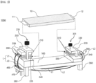
- FIG. 2 shows a first exemplary embodiment of a charging and discharging jig 1000 for impedance measurement of a battery cell 10 of the present invention.
- a charging and discharging jig for impedance measurement of the battery cell 10 of the present invention includes: a jig body 100 on which the battery cell 10 is mounted in a longitudinal direction; a first bus bar 200 and a second bus bar 300 installed on both sides of the jig body 100 and to which lead parts 11 and 12 of both ends of the battery cell 10 are each coupled; an impedance measuring board 400 installed in the jig body 100; and a conducting line L for impedance measurement connecting the first bus bar 200, the impedance measuring board 400, and the second bus bar 300 to constitute an impedance measuring circuit, and a part of the conducting line L for impedance measurement has a part facing a wide surface of the battery cell and extending in the longitudinal direction of the battery cell 10.
- the battery cell 10 is installed in the jig body 100 in the longitudinal direction, that is, so that electrode leads at both ends are disposed on both sides of the jig body 100.
- the jig body 100 is in the form of a fixed jig whose length does not change.
- the jig body 100 may be constituted in the form of a variable jig of which the length can be adjusted in the longitudinal direction in accordance with the length of the battery cell.
- the battery cell 10 is positioned on the jig body 100, and the first and second bus bars on both sides of the charging and discharging jig are connected to the lead parts 11 and 12 of the battery cell 10.
- the first and second bus bars are both connected to the impedance measuring board 400 through the conducting line L for impedance measurement.
- the impedance measuring board 400 of the present invention corresponds to the conventional impedance measuring device, and is constituted in the form of a small substrate required for impedance measurement by greatly simplifying the detailed configuration of a complex impedance measuring device. Therefore, by being made as a small substrate, the impedance measuring board can be easily introduced into a temperature chamber when measuring the impedance in the temperature chamber.
- the impedance measuring board is installed in the jig body. As a result, the length of the conducting line for impedance measurement constituted through the leads of both ends of the battery cell and the impedance measuring board is greatly shortened. That is, since an impedance measuring unit is installed in the charging and discharging jig, there is no need to extend the conducting line at length to the outside as in the conventional art.
- the impedance measuring board 400 of the present invention includes an AC signal source S configured to transmit an AC signal to the battery cell 10, a voltmeter V configured to measure a voltage difference between both ends of the battery cell 10, and an ammeter A configured to measure a current.
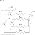
- FIG. 3 illustrates a circuit for sensing voltages applied to both ends of the lead parts 11 and 12 of the battery cell 10 by a four-terminal method.
- the conducting line L connected to the AC signal source S and the voltmeter V is connected to both ends of the battery cell 10.
- the conducting line L for impedance measurement is composed of a signal line L1 configured to apply an AC signal to the battery cell and a sensing line L2 configured to measure a voltage of the battery cell.
- the signal line L1 and the sensing line L2 are connected to the battery cell.
- the battery cell 10 contains a predetermined impedance component, a potential difference (voltage) is generated at both ends of the lead parts 11 and 12 of the battery cell 10 by the application of the AC current.
- the current moving through the conducting line L is measured by the ammeter A, and the voltage difference between both ends of the battery cell 10 may be measured by the voltmeter V.
- the impedance of the battery cell 10 may be measured through the measured values of the ammeter A and the voltmeter V.
- the ammeter A and the voltmeter V provided in the impedance measuring board 400 are connected to an external computing device or display device, so that the current and voltage may be visually expressed.
- the computing device may calculate the impedance of the battery cell 10 by dividing the voltage value by the AC current value, and the calculated impedance value may be displayed on the display device.
- the first bus bar 200 and the second bus bar 300 coupled to the lead parts 11 and 12 of the battery cell 10 and the impedance measuring board 400 are connected by the signal line L1 and the sensing line L2.
- the signal line L1 and the sensing line L2 may be coupled to the first and second bus bars by a coupling member C or the like, respectively.
- the coupling member C may be a screw member for coupling the signal line and the sensing line to the bus bar, but is not limited thereto.
- the signal line L1 is connected to the AC signal source S and the ammeter A of the impedance measuring board 400, and the sensing line L2 is connected to the voltmeter V of the impedance measuring board 400.
- the AC signal source S and the ammeter A of the impedance measuring board 400 are connected to the second bus bar 300 by the signal line L1, and the voltmeter V is connected to the second bus bar 300 by the sensing line L2.
- the conducting line L for impedance measurement of the present invention preferably constitutes a loop connecting the first bus bar 200, the impedance measuring board 400, and the second bus bar 300. Referring to FIG. 2 , it can be seen that the conducting line L extends from the first bus bar 200 to the second bus bar 300 across the impedance measuring board 400, and a part of the conducting line L (signal line: L1 and sensing line: L2) constituting the loop extends in the longitudinal direction of the battery cell 10 along the bottom surface of the jig body 100.
- the charging and discharging jig of the present invention includes the first bus bar 200 and the second bus bar 300 coupled to the lead parts 11 and 12 at both ends of the battery cell 10.
- the first and second bus bars are inserted into and positioned in bus bar coupling frames 230 and 330 in which installation holes are formed so that the bus bars may be inserted thereinto.
- the first and second bus bars are composed of upper bus bars 210 and 310 and lower bus bars 220 and 320 located below the upper bus bars 210 and 310, respectively, and the conducting line L for impedance measurement is connected to the upper bus bars 210 and 310 or the lower bus bars 220 and 320.
- the conducting line L for impedance measurement is connected to the upper bus bars 210 and 310
- the lower bus bars 220 and 320 are separately connected to a charging and discharging device configured to charge and discharge the battery cell 10 by the conducting line L.
- the upper bus bars 210 and 310 or the lower bus bars 220 and 320 of the first bus bar 200 and the second bus bar 300 may each be separated into two bus bars. More preferably, among the upper bus bars 210 and 310 and the lower bus bars 220 and 320, the bus bars connected to the conducting line L for impedance measurement may be separated into two bus bars again. As described above, since the present invention measures the impedance using the four-terminal method, the upper bus bar or the lower bus bar is divided into two pieces so that a plurality of conducting lines may be connected to each of the separated bus bars.
- the upper bus bars 210 and 310 of the first bus bar 200 and the second bus bar 300 are each separated into two bus bars, and the signal line L1 and the sensing line L2 are connected to each of the separated bus bars.
- insulators 250 and 350 are installed between the upper bus bars 210 and 310 and the bus bar coupling frames 230 and 330, and the insulators 250 and 350 are coupled to upper parts of the upper bus bars.
- Adjustment screw parts 231 and 331 on the bus bar coupling frames 230 and 330 are screw-coupled to the insulators 250 and 350 through the bus bar coupling frames 230 and 330. Therefore, when the adjustment screw parts 231 and 331 are rotated, the insulators 250 and 350 and the upper bus bars 210 and 310 are lifted up and down, and accordingly, the lead parts 11 and 12 of the battery cell 10 may be easily inserted and removed between the upper bus bars 210 and 310 and the lower bus bars 220 and 320.
- bus bar coupling frames 230 and 330 configured to fix the first and second bus bars and the insulators 250 and 350 are fixed to both sides of the jig body 100, and at this time, bus bar support members 240 and 340 may be further interposed as needed between the bus bar coupling frames 230 and 330 and the jig body 100 for adjusting the height of the bus bars and supporting the bus bar coupling frames 230 and 330.
- the jig body 100 of the present invention may further include pedestals 260 and 360 installed on both lower sides thereof.
- the pedestals 260 and 360 are coupled to the jig body 100 and serve to stably support the jig body 100.
- the impedance measuring board 400 is installed close to the jig body 100, so that the length of the conducting line L may be reduced as much as possible.
- the impedance measuring board 400 may be installed on the upper part of the jig body 100 or on the lower part of the jig body as shown in FIG. 2 .
- the impedance measuring board 400 is installed on the pedestals 260 and 360 or on the lower part of the jig body 100 adjacent to the pedestals 260 and 360.
- the impedance measuring board 400 may be screwed to the pedestals 260 and 360 or to the lower part of the jig body 100, or may be adhesively coupled.
- the present invention is not limited thereto, and it may be installed at a desired location using any means that can fix the impedance measuring board 400.
- the impedance measuring board 400 may be installed on a support 410 for the impedance measuring board 400 that can support the impedance measuring board 400, and at this time, the support 410 for the impedance measuring board 400 may be preferably coupled to the pedestals 260 and 360 included on both sides of the lower part of the jig body 100.
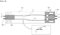
- FIG. 4 is a bottom view of the charging and discharging jig for impedance measurement of FIG. 2 .
- a support member 500 for the conducting line L configured to support a wire extending in the longitudinal direction of the battery cell 10 along the bottom surface of the jig body 100 may be installed on the bottom surface of the jig body 100 of the present invention.
- the support member 500 for the conducting line L is perforated from one side to the other side, and the conducting line L is hung through the perforation. At this time, the size of the perforation should be greater than the thickness of the conducting line L, and the movement of the conducting line L in the longitudinal direction of the battery cell 10 should not be disturbed by the support member 500 for the conducting line L.
- the conducting line L is reliably supported by the charging and discharging jig by the conducting line support member 500 to prevent a change in tension of the conducting line. That is, since the conducting line is stably supported by the conducting line support member and thus the length of the conducting line does not change, the accuracy of impedance measurement can be improved.
- FIG. 5 is a bottom view of a charging and discharging jig for impedance measurement of a battery cell according to another exemplary embodiment of the present invention.
- a fixing jig 600 configured to fix both sides of the conducting line L extending in the longitudinal direction of the battery cell 10 along the bottom surface of the jig body 100 may be installed.
- the fixing jig 600 includes a shape in which the conductive line L can be inserted, and the conductive line L inserted into the fixing jig 600 is limited in movement and fixed, unlike the support member.
- Impedance measurement may be easily performed by installing the fixing jig 600 at a position where the conducting line L is to be fixed, and fixing the conducting line L to the bottom of the jig body 100 by inserting the conducting line L into the fixing jig 600.
- the accuracy of impedance measurement is improved as the conducting line is fixedly coupled to the charging and discharging jig without floating by the conducting line support member 500 and the fixing jig.
- FIG. 6 is a bottom view of a charging and discharging jig for impedance measurement of a battery cell according to still another exemplary embodiment of the present invention.
- the impedance measuring board 400 is installed in the middle of the bottom surface of the jig body 100.
- the impedance measuring board 400 since the impedance measuring board 400 is installed in the jig body 100, the length of the conducting line for impedance measurement is shortened as described above.
- the impedance measuring board 400 may be installed on an upper part, a side part, and a lower part of the jig body.
- it when installed on the upper part of the jig body 100, it may be an obstacle to installation of the battery cell on the jig, so that it is preferable to install the impedance measuring board on the side part or the lower part of the jig body.
- the bus bars are installed on both sides of the jig body, it may be better to install the impedance measuring board on the lower part of the jig body in consideration of bus bar installation space.
- the impedance measuring board When the impedance measuring board is installed on the lower part the jig body 100, it may be installed on one of both sides of the jig body 100 as shown in FIG. 2 .
- FIG. 6 it is also possible to install the impedance measuring board in the middle of the bottom surface of the jig body 100. The important thing is to measure the impedance while shortening the length of the conducting line for impedance measurement by coupling the impedance measuring board on a line in which the conducting line for impedance measurement extends.
- the impedance measuring board 400 As the impedance measuring board 400 is installed in the middle of the jig body 100, a part of the conducting line L constituting the loop is drawn out to both sides of the impedance measuring board 400 and extends toward each of the first bus bar 200 and the second bus bar 300. At this time, even if the conducting line L is drawn out to both sides of the impedance measuring board 400, a magnetic field offsetting effect can be maintained because the conducting line L is still in a position where it faces the wide surface of the battery cell 10.
- FIG. 7 is a perspective view of a charging and discharging jig for impedance measurement of a battery cell according to another exemplary embodiment of the present invention.
- This exemplary embodiment is in the form of a variable jig in which the charging and discharging jig for impedance measurement may be displaced in the longitudinal direction.
- a jig body 100 includes a fixed block 110 and a movable block 120 slidably coupled to the fixed block 110, a first bus bar 200 is installed on one side of the fixed block 110, and a second bus bar 300 is installed on one side of the movable block 120.
- the jig body 100 of the present invention can be variably deformed to measure an impedance in accordance with the length of the battery cell 10.
- the jig body 100 includes the fixed block 110 and the movable block 120 sliding in the longitudinal direction of the battery cell 10 with respect to the fixed block 110.
- a conducting line L extending along the bottom surface of the jig body 100 should be installed assuming that the fixed block 110 and the movable block 120 are as far away as possible so that the jig body 100 can be freely deformed.
- the movable block 120 may be slidably coupled to any one of the bottom surface and the upper surface of the fixed block 110.
- an impedance measuring board 400 be installed on the bottom surface of the block located lower than the other block.
- the impedance measuring board 400 is installed on the lower surface of the fixed block 110 located relatively lower. Coupling by sliding of the movable block 120 and the fixed block 110 may be performed by coupling guide slits 140 and sliding support members 130.
- the guide slits 140 may be formed on both sides in a width direction of one of the fixed block 110 and the movable block 120, and the sliding support members 130 inserted into the guide slits may be installed on the other of the fixed block 110 and the movable block 120.
- the sliding support members 130 slide along the guide slits 140
- the movable block 120 may slide along the fixed block 110.
- the guide slits 140 may be installed in any one of the fixed block 110 and the movable block 120.
- the guide slits 140 are formed on both sides of the movable block 120 in the width direction
- the sliding support members 130 are formed on both sides of the fixed block 110 in the width direction.
- Each of the sliding support members 130 may have a body part inserted into the guide slit 140 and screwed to the fixed block 110 or screwed to the movable block 120, and a head part having a width greater than that of the guide slit. Since the head part has a width greater than that of the guide slit 140, separation of the sliding support member 130 from the guide slit 140 may be prevented, and thus separation of the movable block 120 from the fixed block 110 may be prevented. In addition, since the body part of the sliding support member 130 has a screw thread and is screw-coupled to the fixed block 110 or the movable block 120, the movable block 120 may be fixed to the fixed block 110 by adjusting the degree of the screw coupling.
- the head part presses edges of both sides of the guide slit 140 so that the movable block 120 may be fixed to the fixed block 110.
- FIG. 8 is a bottom view of the charging and discharging jig for impedance measurement of FIG. 7 .
- FIG. 8 shows an exemplary embodiment in which a support member 500 for the conducting line L is applied to the charging and discharging jig for impedance measurement of the battery cell 10 of the second exemplary embodiment.
- the conducting line L of the present invention should deviate as little as possible from the wide surface range of the battery cell 10.
- the support member 500 for the conducting line L is installed at an appropriate position when the movable block 120 slides on the fixed block 110 and the deformation of the conducting line L increases, thereby minimizing the deformation of the conducting line L.
- the conducting line can be maintained in the jig without sagging by installing the support member 500 in the middle and on one side of the jig, and installing the impedance measuring board on the other side to connect the conducting line.
- the conducting line may inevitably sag downward, but since the conducting line is supported by the plurality of support members 500, the degree of sagging can be reduced.
- the magnetic field caused by the current flowing in the battery cell may be offset by the magnetic field caused by the conducting line.
Landscapes
- Engineering & Computer Science (AREA)
- Manufacturing & Machinery (AREA)
- Chemical & Material Sciences (AREA)
- Chemical Kinetics & Catalysis (AREA)
- Electrochemistry (AREA)
- General Chemical & Material Sciences (AREA)
- Physics & Mathematics (AREA)
- General Physics & Mathematics (AREA)
- Power Engineering (AREA)
- Secondary Cells (AREA)
- Measurement Of Resistance Or Impedance (AREA)
Abstract
Description
- The present invention relates to a charging and discharging jig for impedance measurement of a battery cell.
- This application claims the benefit of priority based on
Korean Patent Application No. 10-2021-0124886, filed on September 17, 2021 - Recently, secondary batteries capable of charging and discharging have been widely used as energy sources of wireless mobile devices. In addition, secondary batteries have attracted attention as an energy source of an electric vehicle, a hybrid electric vehicle, etc., which are proposed as a solution to air pollution of existing gasoline vehicles and diesel vehicles using fossil fuel. Therefore, the types of applications using secondary batteries are currently becoming much more diverse due to the advantages of secondary batteries, and secondary batteries are expected to be applied to many fields and products in the future.
- Such secondary batteries may be classified into lithium ion batteries, lithium ion polymer batteries, lithium polymer batteries, etc., depending on the composition of the electrolyte and the electrode, and among them, the use of lithium-ion polymer batteries that are less likely to leak electrolyte and are easy to manufacture is increasing. In general, secondary batteries are classified depending on the shape of a battery case into cylindrical batteries and prismatic batteries in which an electrode assembly is embedded in a cylindrical or prismatic metal can, and pouch-type batteries in which the electrode assembly is embedded in a pouch-type case of an aluminum laminate sheet. The electrode assembly embedded in the battery case is composed of a positive electrode, a negative electrode, and a separator interposed between the positive electrode and the negative electrode, and is a power generating element capable of charging and discharging. The electrode assembly is classified into a jelly-roll type wound with a separator interposed between a positive electrode and a negative electrode which are long sheet-shaped and are coated with active materials, or a stack type in which a plurality of positive electrodes and negative electrodes of a predetermined size are sequentially stacked with separators interposed therebetween.
- In order to inspect the safety and performance of such secondary batteries, various tests may be performed. Among them, a method of evaluating the safety and performance of a battery by measuring the impedance of the battery cell is being relied upon more and more. By measuring the impedance of the battery cell in this way, main factors such as life, capacity, and charge state can be estimated.
- The measurement results of impedance of a battery cell vary depending on the length change or movement of a measuring conducting line (wire). In the case of a cylindrical battery with a short length and a large impedance value, the influence of a wire is relatively less, but in the case of a medium- or large-sized pouch-type battery with a long length and a small impedance value, the measured impedance value has a large deviation according to the length or movement of a wire. The impedance of such a battery cell can be measured by installing a battery cell in a charging and discharging jig that can be displaced in a longitudinal direction of the battery cell.
- Specifically, the impedance is measured by installing leads each having different polarities of a battery cell on charging and discharging bus bars installed on both sides of a charging and discharging jig, and connecting wires to the charging and discharging bus bars.
- Conventionally, the impedance of a battery cell was measured by installing a battery cell and a charging and discharging jig for impedance measurement in which the battery cell is installed in a temperature chamber, and connecting an impedance measuring device (for example, an EIS measuring device) and the charging and discharging jig with a conducting line from the outside. Since the impedance measuring device and the charging and discharging jig occupy a large volume, there has been difficulty installing the impedance measuring device and the charging and discharging jig in the temperature chamber. Thus, when the impedance measuring device is installed outside the temperature chamber, the length of the conducting line connecting the battery cell and the impedance measuring device naturally increases. Thus, as the length of the conducting line increases, the impedance component (inductance) according to the length of the conducting line increases, which acts as noise in the impedance measurement of the battery cell, making it difficult to accurately measure the impedance of the battery cell. Moreover, when the conducting line is extended outside the battery cell at length, a magnetic field caused by the current flowing through the battery cell and a magnetic field caused by the conducting line cannot be offset, and therefore an impedance disturbance effect due to the noise caused by this magnetic field inevitably occurs. This problem is more serious in the case of a medium- or large-sized pouch type battery having a long battery cell length and a small impedance value.
- Hence, there is a need to develop a device capable of more accurately measuring the impedance of a battery cell by reducing the effect of a magnetic field caused by the current of the battery cell and a conducting line while reducing the length of the conducting line for impedance measurement.
-
Korean Registered Patent Publication No. 10-1359902 - The present invention is directed to providing a charging and discharging jig for impedance measurement of a battery cell in which a conducting line for impedance measurement can be formed short and the conducting line can be installed to extend in parallel with the battery cell while facing the battery cell.
- A charging and discharging jig for impedance measurement of a battery cell of the present invention for solving the above problems includes: a jig body on which a battery cell is mounted in a longitudinal direction; a first bus bar and a second bus bar installed on both sides of the jig body and to which lead parts of both ends of the battery cell are each coupled; an impedance measuring board installed in the jig body; and a conducting line for impedance measurement connecting the first bus bar, the impedance measuring board, and the second bus bar to constitute an impedance measuring circuit, and a part of the conducting line for impedance measurement has a part facing a wide surface of the battery cell and extending in the longitudinal direction of the battery cell.
- The conducting line for impedance measurement may include a signal line configured to apply an AC signal to the battery cell and a sensing line configured to measure a voltage of the battery cell.
- For example, the first bus bar and the second bus bar may each be constituted as an upper bus bar and a lower bus bar, and the conducting line for impedance measurement may be connected to the upper bus bar or the lower bus bar.
- As a specific example, the upper bus bars of the first bus bar and the second bus bar may each be separated into two bus bars, and the signal line and the sensing line may be connected to each of the separated bus bars.
- As an example, the impedance measuring board may include an AC signal source and an ammeter connected to the signal line, and a voltmeter connected to the sensing line.
- Specifically, the impedance measuring board may be installed on a lower part of the jig body, and the conducting line for impedance measurement may constitutes a loop connecting the first bus bar, the impedance measuring board, and the second bus bar, and a part of the conducting line constituting the loop may extend in the longitudinal direction of the battery cell along a bottom surface of the jig body.
- As another example, the charging and discharging jig may further include pedestals installed on both lower sides of the jig body, and the impedance measuring board may be installed on the pedestal or the lower part of the jig body adjacent to the pedestals.
- As another example, the charging and discharging jig may further include pedestals installed on both lower sides of the jig body, and the impedance measuring board may be installed on a measuring board support coupled to the pedestals.
- As another example, a conducting line support member configured to support the conducting line for impedance measurement extending in the longitudinal direction of the battery cell along the bottom surface of the jig body may be installed on the bottom surface of the jig body.
- As another example, fixing jigs configured to fix both sides of a conducting line extending in the longitudinal direction of the battery cell along the bottom surface of the jig body may be installed on both sides of the bottom surface of the jig body.
- As an example, the impedance measuring board may be installed in the middle of the bottom surface of the jig body, and the part of the conducting line constituting the loop may be drawn out to both sides of the impedance measuring board and extend toward each of the first bus bar and the second bus bar.
- As another exemplary embodiment of the present invention, the jig body may include a fixed block and a movable block slidably coupled to the fixed block, the first bus bar may be installed on one side of the fixed block, and the second bus bar may be installed on one side of the movable block.
- As an example, the movable block may be slidably coupled to an upper surface of the fixed block.
- As a specific example, guide slits may be formed on both sides in a width direction of one of the fixed block and the movable block, and sliding support members inserted into the guide slits may be installed in the other of the fixed block and the movable block.
- More specifically, each of the sliding support members may have a body part inserted into the guide slit and screwed to the fixed block or the movable block, and a head part having a width greater than that of the guide slit.
- According to the present invention, by reducing the length of a conducting line for impedance measurement, the influence of an inductance according to the length of a wire can be minimized, thereby reducing the noise of impedance measurement.
- In addition, since a conducting line for impedance measurement has a structure that can be installed to face a wide surface of a battery cell and extend in a longitudinal direction of the battery cell, the impedance of the battery cell can be more accurately measured by offsetting a magnetic field caused by the battery cell and a magnetic field caused by the conducting line.
-
-
FIG. 1 is a schematic diagram illustrating a difference between impedance measuring mechanisms by a conventional impedance measuring device and a charging and discharging jig for impedance measurement of the present invention. -
FIG. 2 is a perspective view of a charging and discharging jig for impedance measurement of a battery cell according to one exemplary embodiment of the present invention. -
FIG. 3 is a schematic diagram illustrating a connection relationship between a conducting line for impedance measurement and an impedance measuring board and an impedance measuring circuit constituted by the conducting line and the measuring board according to the present invention. -
FIG. 4 is a bottom view of the charging and discharging jig for impedance measurement ofFIG. 2 . -
FIG. 5 is a bottom view of a charging and discharging jig for impedance measurement of a battery cell according to another exemplary embodiment of the present invention. -
FIG. 6 is a bottom view of a charging and discharging jig for impedance measurement of a battery cell according to still another exemplary embodiment of the present invention. -
FIG. 7 is a perspective view of a charging and discharging jig for impedance measurement of a battery cell according to another exemplary embodiment of the present invention. -
FIG. 8 is a bottom view of the charging and discharging jig for impedance measurement ofFIG. 7 . - Hereinafter, the detailed configuration of the present invention will be described in detail with reference to the accompanying drawings and various exemplary embodiments. The exemplary embodiments described below are illustratively shown to help with understanding of the present invention, the accompanying drawings may not be illustrated on an actual scale but sizes of some components may be exaggerated in order to help with understanding of the present invention.
- In the present invention, since various modifications may be made and various forms may be applied, specific exemplary embodiments are illustrated in the drawings and described in detail in the text. However, this is not intended to limit the present invention to the specific disclosed forms, which should be understood to include all modifications, equivalents and substitutes included in the spirit and scope of the present invention.
- As described above, the present invention provides a charging and discharging jig for impedance measurement of a
battery cell 10 in which a conducting line L for impedance measurement can be formed short and the conducting line can be installed to extend in parallel with thebattery cell 10 while facing thebattery cell 10. -
FIG. 1 is a schematic diagram illustrating a difference between impedance measuring mechanisms by a conventional impedance measuring device and animpedance measuring board 400 of the present invention. - Conventionally, a battery cell and a charging and discharging jig for impedance measurement are installed in a temperature chamber, and an impedance measuring device (e.g., EIS measuring device) and a charging and discharging device are installed outside the temperature chamber to charge and discharge the battery cell and measure the impedance of the battery cell at the same time. Since the impedance measuring device and the charging and discharging device occupy a significant volume, the impedance measuring device and the charging and discharging device cannot be installed in the temperature chamber due to the size limitation of the space of the temperature chamber. For this reason, the configuration of the conducting line for impedance measurement during charging and discharging of the conventional battery cell had to be as shown in
FIG. 1(a) . Referring toFIG. 1 , when measuring the impedance of a battery cell, a conducting line constitutes a loop shape connecting both leads of the battery cell and an impedance measuring device that is not shown. In this case, as described above, when the impedance measuring device is installed outside the temperature chamber, the loop of the conducting line connected to the battery cell lead becomes longer as shown inFIG. 1(a) . Accordingly, the length of the conducting line increases and an inductance component of the conducting line increases, which acts as noise when measuring the impedance of the battery cell. In addition, since the conducting line is in the form of a long extension, whenever the wire is connected to the battery cell, there is a problem that the arrangement of the wire slightly changes and the impedance measurement result changes accordingly. In addition, in the case ofFIG. 1(a) , a magnetic field is generated by the current flowing along the battery cell. An impedance value of the battery cell may be disturbed by this magnetic field. - On the other hand, as shown in
FIG. 1(b) , when the conducting line for impedance measurement is disposed adjacent to the battery cell, the length of the conducting line is shortened, and thus the influence of an inductance can be significantly reduced. In addition, inFIG. 1(b) , the conducting line for impedance measurement faces a wide surface of the battery cell and extends in parallel to the longitudinal direction of the battery cell. In this case, as shown inFIG. 1(b) , because the directions of the current flowing along the battery cell and the current flowing along the conducting line are opposite, the directions of the magnetic fields caused by the currents are also opposite. That is, as shown inFIG. 1(b) , when the conducting line (circuit) for impedance measurement can be constituted, the magnetic fields of the battery cell and the conducting line may be offset from each other. In this case, the impedance of the battery cell may be more accurately measured without being disturbed by the magnetic fields. - The present invention significantly shortens the length of a conducting line for impedance measurement connected to a battery cell by directly installing an impedance measuring board in a charging and discharging jig for impedance measurement of the battery cell, and excludes the influence of a magnetic field by extending the conducting line as shown in
FIG. 1(b) . - Specific details regarding a charging and discharging jig for impedance measurement of a
battery cell 10 of the present invention will be described with reference to exemplary embodiments and drawings. -
FIG. 2 shows a first exemplary embodiment of a charging and dischargingjig 1000 for impedance measurement of abattery cell 10 of the present invention. - Referring to
FIG. 2 , a charging and discharging jig for impedance measurement of thebattery cell 10 of the present invention includes: ajig body 100 on which thebattery cell 10 is mounted in a longitudinal direction; afirst bus bar 200 and asecond bus bar 300 installed on both sides of thejig body 100 and to which leadparts battery cell 10 are each coupled; animpedance measuring board 400 installed in thejig body 100; and a conducting line L for impedance measurement connecting thefirst bus bar 200, theimpedance measuring board 400, and thesecond bus bar 300 to constitute an impedance measuring circuit, and a part of the conducting line L for impedance measurement has a part facing a wide surface of the battery cell and extending in the longitudinal direction of thebattery cell 10. - The
battery cell 10 is installed in thejig body 100 in the longitudinal direction, that is, so that electrode leads at both ends are disposed on both sides of thejig body 100. InFIG. 2 , thejig body 100 is in the form of a fixed jig whose length does not change. However, as will be described below, thejig body 100 may be constituted in the form of a variable jig of which the length can be adjusted in the longitudinal direction in accordance with the length of the battery cell. - First, in order to measure the impedance of the
battery cell 10, thebattery cell 10 is positioned on thejig body 100, and the first and second bus bars on both sides of the charging and discharging jig are connected to thelead parts battery cell 10. The first and second bus bars are both connected to theimpedance measuring board 400 through the conducting line L for impedance measurement. - The
impedance measuring board 400 of the present invention corresponds to the conventional impedance measuring device, and is constituted in the form of a small substrate required for impedance measurement by greatly simplifying the detailed configuration of a complex impedance measuring device. Therefore, by being made as a small substrate, the impedance measuring board can be easily introduced into a temperature chamber when measuring the impedance in the temperature chamber. In particular, in the present invention, the impedance measuring board is installed in the jig body. As a result, the length of the conducting line for impedance measurement constituted through the leads of both ends of the battery cell and the impedance measuring board is greatly shortened. That is, since an impedance measuring unit is installed in the charging and discharging jig, there is no need to extend the conducting line at length to the outside as in the conventional art. - Specifically, the
impedance measuring board 400 of the present invention includes an AC signal source S configured to transmit an AC signal to thebattery cell 10, a voltmeter V configured to measure a voltage difference between both ends of thebattery cell 10, and an ammeter A configured to measure a current. -
FIG. 3 illustrates a circuit for sensing voltages applied to both ends of thelead parts battery cell 10 by a four-terminal method. Referring to this, it can be seen that the conducting line L connected to the AC signal source S and the voltmeter V is connected to both ends of thebattery cell 10. The conducting line L for impedance measurement is composed of a signal line L1 configured to apply an AC signal to the battery cell and a sensing line L2 configured to measure a voltage of the battery cell. InFIG. 3 , the signal line L1 and the sensing line L2 are connected to the battery cell. By applying an AC signal from the AC signal source S, an AC current is applied to thebattery cell 10 through the signal line L1. Since thebattery cell 10 contains a predetermined impedance component, a potential difference (voltage) is generated at both ends of thelead parts battery cell 10 by the application of the AC current. At this time, the current moving through the conducting line L is measured by the ammeter A, and the voltage difference between both ends of thebattery cell 10 may be measured by the voltmeter V. The impedance of thebattery cell 10 may be measured through the measured values of the ammeter A and the voltmeter V. The ammeter A and the voltmeter V provided in theimpedance measuring board 400 are connected to an external computing device or display device, so that the current and voltage may be visually expressed. The computing device may calculate the impedance of thebattery cell 10 by dividing the voltage value by the AC current value, and the calculated impedance value may be displayed on the display device. - Referring back to
FIG. 2 , it can be seen that thefirst bus bar 200 and thesecond bus bar 300 coupled to thelead parts battery cell 10 and theimpedance measuring board 400 are connected by the signal line L1 and the sensing line L2. The signal line L1 and the sensing line L2 may be coupled to the first and second bus bars by a coupling member C or the like, respectively. The coupling member C may be a screw member for coupling the signal line and the sensing line to the bus bar, but is not limited thereto. The signal line L1 is connected to the AC signal source S and the ammeter A of theimpedance measuring board 400, and the sensing line L2 is connected to the voltmeter V of theimpedance measuring board 400. The AC signal source S and the ammeter A of theimpedance measuring board 400 are connected to thesecond bus bar 300 by the signal line L1, and the voltmeter V is connected to thesecond bus bar 300 by the sensing line L2. - The conducting line L for impedance measurement of the present invention preferably constitutes a loop connecting the
first bus bar 200, theimpedance measuring board 400, and thesecond bus bar 300. Referring toFIG. 2 , it can be seen that the conducting line L extends from thefirst bus bar 200 to thesecond bus bar 300 across theimpedance measuring board 400, and a part of the conducting line L (signal line: L1 and sensing line: L2) constituting the loop extends in the longitudinal direction of thebattery cell 10 along the bottom surface of thejig body 100. - Meanwhile, the charging and discharging jig of the present invention includes the
first bus bar 200 and thesecond bus bar 300 coupled to thelead parts battery cell 10. Referring toFIG. 2 , the first and second bus bars are inserted into and positioned in bus bar coupling frames 230 and 330 in which installation holes are formed so that the bus bars may be inserted thereinto. - The first and second bus bars are composed of upper bus bars 210 and 310 and
lower bus bars lower bus bars lower bus bars battery cell 10 by the conducting line L. - The upper bus bars 210 and 310 or the
lower bus bars first bus bar 200 and thesecond bus bar 300 may each be separated into two bus bars. More preferably, among the upper bus bars 210 and 310 and thelower bus bars - In the exemplary embodiment of
FIG. 2 , the upper bus bars 210 and 310 of thefirst bus bar 200 and thesecond bus bar 300 are each separated into two bus bars, and the signal line L1 and the sensing line L2 are connected to each of the separated bus bars. - Meanwhile,
insulators insulators Adjustment screw parts insulators adjustment screw parts insulators lead parts battery cell 10 may be easily inserted and removed between the upper bus bars 210 and 310 and thelower bus bars - The bus bar coupling frames 230 and 330 configured to fix the first and second bus bars and the
insulators jig body 100, and at this time, busbar support members jig body 100 for adjusting the height of the bus bars and supporting the bus bar coupling frames 230 and 330. - The
jig body 100 of the present invention may further includepedestals pedestals jig body 100 and serve to stably support thejig body 100. - Another characteristic point of the present invention is that the
impedance measuring board 400 is installed close to thejig body 100, so that the length of the conducting line L may be reduced as much as possible. Theimpedance measuring board 400 may be installed on the upper part of thejig body 100 or on the lower part of the jig body as shown inFIG. 2 . According to one exemplary embodiment, theimpedance measuring board 400 is installed on thepedestals jig body 100 adjacent to thepedestals impedance measuring board 400 may be screwed to thepedestals jig body 100, or may be adhesively coupled. However, the present invention is not limited thereto, and it may be installed at a desired location using any means that can fix theimpedance measuring board 400. According to another exemplary embodiment, theimpedance measuring board 400 may be installed on asupport 410 for theimpedance measuring board 400 that can support theimpedance measuring board 400, and at this time, thesupport 410 for theimpedance measuring board 400 may be preferably coupled to thepedestals jig body 100. -
FIG. 4 is a bottom view of the charging and discharging jig for impedance measurement ofFIG. 2 . - As shown in
FIG. 4 , asupport member 500 for the conducting line L configured to support a wire extending in the longitudinal direction of thebattery cell 10 along the bottom surface of thejig body 100 may be installed on the bottom surface of thejig body 100 of the present invention. Thesupport member 500 for the conducting line L is perforated from one side to the other side, and the conducting line L is hung through the perforation. At this time, the size of the perforation should be greater than the thickness of the conducting line L, and the movement of the conducting line L in the longitudinal direction of thebattery cell 10 should not be disturbed by thesupport member 500 for the conducting line L. The conducting line L is reliably supported by the charging and discharging jig by the conductingline support member 500 to prevent a change in tension of the conducting line. That is, since the conducting line is stably supported by the conducting line support member and thus the length of the conducting line does not change, the accuracy of impedance measurement can be improved. -
FIG. 5 is a bottom view of a charging and discharging jig for impedance measurement of a battery cell according to another exemplary embodiment of the present invention. - On the bottom surface of the
jig body 100 of the present invention, as shown inFIG. 5 , a fixingjig 600 configured to fix both sides of the conducting line L extending in the longitudinal direction of thebattery cell 10 along the bottom surface of thejig body 100 may be installed. The fixingjig 600 includes a shape in which the conductive line L can be inserted, and the conductive line L inserted into the fixingjig 600 is limited in movement and fixed, unlike the support member. Impedance measurement may be easily performed by installing the fixingjig 600 at a position where the conducting line L is to be fixed, and fixing the conducting line L to the bottom of thejig body 100 by inserting the conducting line L into the fixingjig 600. The accuracy of impedance measurement is improved as the conducting line is fixedly coupled to the charging and discharging jig without floating by the conductingline support member 500 and the fixing jig. -
FIG. 6 is a bottom view of a charging and discharging jig for impedance measurement of a battery cell according to still another exemplary embodiment of the present invention. - In this exemplary embodiment, the
impedance measuring board 400 is installed in the middle of the bottom surface of thejig body 100. In the present invention, since theimpedance measuring board 400 is installed in thejig body 100, the length of the conducting line for impedance measurement is shortened as described above. In this case, theimpedance measuring board 400 may be installed on an upper part, a side part, and a lower part of the jig body. However, when installed on the upper part of thejig body 100, it may be an obstacle to installation of the battery cell on the jig, so that it is preferable to install the impedance measuring board on the side part or the lower part of the jig body. In addition, since the bus bars are installed on both sides of the jig body, it may be better to install the impedance measuring board on the lower part of the jig body in consideration of bus bar installation space. When the impedance measuring board is installed on the lower part thejig body 100, it may be installed on one of both sides of thejig body 100 as shown inFIG. 2 . In addition, as shown inFIG. 6 , it is also possible to install the impedance measuring board in the middle of the bottom surface of thejig body 100. The important thing is to measure the impedance while shortening the length of the conducting line for impedance measurement by coupling the impedance measuring board on a line in which the conducting line for impedance measurement extends. - As the
impedance measuring board 400 is installed in the middle of thejig body 100, a part of the conducting line L constituting the loop is drawn out to both sides of theimpedance measuring board 400 and extends toward each of thefirst bus bar 200 and thesecond bus bar 300. At this time, even if the conducting line L is drawn out to both sides of theimpedance measuring board 400, a magnetic field offsetting effect can be maintained because the conducting line L is still in a position where it faces the wide surface of thebattery cell 10. -
FIG. 7 is a perspective view of a charging and discharging jig for impedance measurement of a battery cell according to another exemplary embodiment of the present invention. - This exemplary embodiment is in the form of a variable jig in which the charging and discharging jig for impedance measurement may be displaced in the longitudinal direction. By changing the length of the jig, there is an advantage that the jig length can be adjusted to match different types of battery cells.
- Referring to
FIG. 7 , ajig body 100 includes a fixedblock 110 and amovable block 120 slidably coupled to the fixedblock 110, afirst bus bar 200 is installed on one side of the fixedblock 110, and asecond bus bar 300 is installed on one side of themovable block 120. - According to the second exemplary embodiment, the
jig body 100 of the present invention can be variably deformed to measure an impedance in accordance with the length of thebattery cell 10. Specifically, thejig body 100 includes the fixedblock 110 and themovable block 120 sliding in the longitudinal direction of thebattery cell 10 with respect to the fixedblock 110. Among the conducting lines L used at this time, a conducting line L extending along the bottom surface of thejig body 100 should be installed assuming that the fixedblock 110 and themovable block 120 are as far away as possible so that thejig body 100 can be freely deformed. Themovable block 120 may be slidably coupled to any one of the bottom surface and the upper surface of the fixedblock 110. However, in this case, between two blocks, it is preferable that animpedance measuring board 400 be installed on the bottom surface of the block located lower than the other block. When themovable block 120 is slidably coupled to the upper surface of the fixedblock 110 as shown inFIG. 7 , theimpedance measuring board 400 is installed on the lower surface of the fixedblock 110 located relatively lower. Coupling by sliding of themovable block 120 and the fixedblock 110 may be performed by coupling guide slits 140 and slidingsupport members 130. For example, the guide slits 140 may be formed on both sides in a width direction of one of the fixedblock 110 and themovable block 120, and the slidingsupport members 130 inserted into the guide slits may be installed on the other of the fixedblock 110 and themovable block 120. As the slidingsupport members 130 slide along the guide slits 140, themovable block 120 may slide along the fixedblock 110. At this time, the guide slits 140 may be installed in any one of the fixedblock 110 and themovable block 120. In the exemplary embodiment ofFIG. 7 , the guide slits 140 are formed on both sides of themovable block 120 in the width direction, and the slidingsupport members 130 are formed on both sides of the fixedblock 110 in the width direction. Each of the slidingsupport members 130 may have a body part inserted into the guide slit 140 and screwed to the fixedblock 110 or screwed to themovable block 120, and a head part having a width greater than that of the guide slit. Since the head part has a width greater than that of the guide slit 140, separation of the slidingsupport member 130 from the guide slit 140 may be prevented, and thus separation of themovable block 120 from the fixedblock 110 may be prevented. In addition, since the body part of the slidingsupport member 130 has a screw thread and is screw-coupled to the fixedblock 110 or themovable block 120, themovable block 120 may be fixed to the fixedblock 110 by adjusting the degree of the screw coupling. That is, after the movement of themovable block 120 is completed, when the slidingsupport member 130 is further rotated to move the head part downward, the head part presses edges of both sides of the guide slit 140 so that themovable block 120 may be fixed to the fixedblock 110. -
FIG. 8 is a bottom view of the charging and discharging jig for impedance measurement ofFIG. 7 . -
FIG. 8 shows an exemplary embodiment in which asupport member 500 for the conducting line L is applied to the charging and discharging jig for impedance measurement of thebattery cell 10 of the second exemplary embodiment. In order to maintain the effect of offsetting the magnetic field generated in thebattery cell 10, the conducting line L of the present invention should deviate as little as possible from the wide surface range of thebattery cell 10. Thesupport member 500 for the conducting line L is installed at an appropriate position when themovable block 120 slides on the fixedblock 110 and the deformation of the conducting line L increases, thereby minimizing the deformation of the conducting line L. However, it is necessary to avoid the installation of thesupport member 500 for the conducting line L on a sliding path so that the sliding of themovable block 120 is not disturbed by thesupport member 500 for the conducting line L. As shown inFIG. 8 , the conducting line can be maintained in the jig without sagging by installing thesupport member 500 in the middle and on one side of the jig, and installing the impedance measuring board on the other side to connect the conducting line. In addition, when the movable block moves, the conducting line may inevitably sag downward, but since the conducting line is supported by the plurality ofsupport members 500, the degree of sagging can be reduced. Also in this exemplary embodiment, since a part of the conducting line extends in the longitudinal direction of the battery cell, as shown inFIG. 1(b) , the magnetic field caused by the current flowing in the battery cell may be offset by the magnetic field caused by the conducting line. - The present invention has been described above in more detail through drawings and exemplary embodiments. However, since the configurations described in the drawings or exemplary embodiments, etc. described in the present specification are only one exemplary embodiment of the present invention and do not represent all the technical ideas of the present invention, it should be understood that there may be various equivalents and variations that can replace them at the time of filing of the application.
[Description of Reference Numerals] 10, Z: battery cell 11, 12: lead parts L: conducting line 100: jig body L1: signal line 110: fixed block L2: sensing line 120: movable block A: ammeter 130: sliding support member V: voltmeter 140: guide slit S: AC signal source 200: first bus bar Rwire: conducting line resistance 300: second bus bar 210, 310: upper bus bars C: coupling member 220, 320: lower bus bars 230, 330: bus bar coupling frames 231, 331: adjustment screw parts 240, 340: bus bar support members 250, 350: insulators 260, 360: pedestals 400: impedance measuring board 410: support for the impedance measuring board 500: support member for the conducting line 600: fixing jig
Claims (15)
- A charging and discharging jig for impedance measurement of a battery cell, the charging and discharging jig comprising:a jig body on which a battery cell is mounted in a longitudinal direction;a first bus bar and a second bus bar installed on both sides of the jig body and to which lead parts of both ends of the battery cell are each coupled;an impedance measuring board installed in the jig body; anda conducting line for impedance measurement connecting the first bus bar, the impedance measuring board, and the second bus bar to constitute an impedance measuring circuit,wherein a part of the conducting line for impedance measurement has a part facing a wide surface of the battery cell and extending in the longitudinal direction of the battery cell.
- The charging and discharging jig of claim 1, wherein the conducting line for impedance measurement includes a signal line configured to apply an AC signal to the battery cell, and a sensing line configured to measure a voltage of the battery cell.
- The charging and discharging jig of claim 2, wherein the first bus bar and the second bus bar are each constituted as an upper bus bar and a lower bus bar, and the conducting line for impedance measurement is connected to the upper bus bar or the lower bus bar.
- The charging and discharging jig of claim 3, wherein the upper bus bars of the first bus bar and the second bus bar are each separated into two bus bars, and the signal line and the sensing line are connected to each of the separated bus bars.
- The charging and discharging jig of claim 2, wherein the impedance measuring board includes an AC signal source and an ammeter connected to the signal line, and a voltmeter connected to the sensing line.
- The charging and discharging jig of claim 1, wherein the impedance measuring board is installed on a lower part of the jig body,the conducting line for impedance measurement constitutes a loop connecting the first bus bar, the impedance measuring board, and the second bus bar, anda part of the conducting line constituting the loop extends in the longitudinal direction of the battery cell along a bottom surface of the jig body.
- The charging and discharging jig of claim 6, further comprising pedestals installed on both lower sides of the jig body, wherein the impedance measuring board is installed on the pedestals or the lower part of the jig body adjacent to the pedestals.
- The charging and discharging jig of claim 6, further comprising pedestals installed on both lower sides of the jig body, wherein the impedance measuring board is installed on a measuring board support coupled to the pedestals.
- The charging and discharging jig of claim 6, wherein a conducting line support member configured to support the conducting line for impedance measurement extending in the longitudinal direction of the battery cell along the bottom surface of the jig body is installed on the bottom surface of the jig body.
- The charging and discharging jig of claim 6, wherein fixing jigs configured to fix both sides of a conducting line extending in the longitudinal direction of the battery cell along the bottom surface of the jig body are installed on both sides of the bottom surface of the jig body.
- The charging and discharging jig of claim 6, wherein the impedance measuring board is installed in the middle of the bottom surface of the jig body, and
the part of the conducting line constituting the loop is drawn out to both sides of the impedance measuring board and extends toward each of the first bus bar and the second bus bar. - The charging and discharging jig of claim 1, wherein the jig body includes a fixed block and a movable block slidably coupled to the fixed block, and
the first bus bar is installed on one side of the fixed block and the second bus bar is installed on one side of the movable block. - The charging and discharging jig of claim 12, wherein the movable block is slidably coupled to an upper surface of the fixed block.
- The charging and discharging jig of claim 13, wherein guide slits are formed on both sides in a width direction of one of the fixed block and the movable block, and
sliding support members inserted into the guide slits are installed on the other of the fixed block and the movable block. - The charging and discharging jig of claim 14, wherein each of the sliding support members has a body part inserted into the guide slit and screwed to the fixed block or the movable block, and a head part having a width greater than that of the guide slit.
Applications Claiming Priority (2)
| Application Number | Priority Date | Filing Date | Title |
|---|---|---|---|
| KR1020210124886A KR102788140B1 (en) | 2021-09-17 | 2021-09-17 | Jig for measuring impedance of a battery cell |
| PCT/KR2022/013320 WO2023043107A1 (en) | 2021-09-17 | 2022-09-06 | Charging/discharging jig for measuring battery cell impedance |
Publications (2)
| Publication Number | Publication Date |
|---|---|
| EP4227698A1 true EP4227698A1 (en) | 2023-08-16 |
| EP4227698A4 EP4227698A4 (en) | 2024-05-01 |
Family
ID=85603125
Family Applications (1)
| Application Number | Title | Priority Date | Filing Date |
|---|---|---|---|
| EP22870192.6A Pending EP4227698A4 (en) | 2021-09-17 | 2022-09-06 | Charging/discharging jig for measuring battery cell impedance |
Country Status (5)
| Country | Link |
|---|---|
| US (1) | US12320859B2 (en) |
| EP (1) | EP4227698A4 (en) |
| KR (1) | KR102788140B1 (en) |
| CN (1) | CN116529618B (en) |
| WO (1) | WO2023043107A1 (en) |
Cited By (1)
| Publication number | Priority date | Publication date | Assignee | Title |
|---|---|---|---|---|
| EP4194869A4 (en) * | 2021-08-20 | 2024-08-14 | LG Energy Solution, Ltd. | CHARGE/DISCHARGE TEMPLATE FOR MEASURING BATTERY CELL IMPEDANCE |
Families Citing this family (4)
| Publication number | Priority date | Publication date | Assignee | Title |
|---|---|---|---|---|
| KR20250079993A (en) * | 2023-11-27 | 2025-06-05 | 모나 주식회사 | Eis measurement-based ai diagnosis system and its operation method |
| KR20250104384A (en) * | 2023-12-29 | 2025-07-08 | 주식회사 엘지에너지솔루션 | Secondary battery fixing jig, Secondary battery charging/discharging device and method of using the Same |
| KR20250145341A (en) * | 2024-03-28 | 2025-10-13 | 삼성에스디아이 주식회사 | Jig measuring charaterstic of battery cell for rechargeable battery and appararus including the same |
| KR102911321B1 (en) * | 2024-11-07 | 2026-01-12 | 주식회사 메가터치 | Jig for charging and discharging tests of secondary battery |
Family Cites Families (21)
| Publication number | Priority date | Publication date | Assignee | Title |
|---|---|---|---|---|
| KR20020017367A (en) | 2000-08-30 | 2002-03-07 | 김선영 | control system for internet phone |
| KR20060087163A (en) | 2005-01-28 | 2006-08-02 | (주)갑진 | Noise elimination structure of battery charge / discharge and monitoring device |
| KR101089090B1 (en) * | 2006-12-30 | 2011-12-06 | 주식회사 엘지화학 | Fixture for measuring insulation resistance of battery |
| KR101058388B1 (en) * | 2007-02-08 | 2011-08-22 | 주식회사 엘지화학 | Secondary Battery Inspection Device |
| CN201207060Y (en) * | 2008-05-21 | 2009-03-11 | 深圳市比克电池有限公司 | General resistance detecting clamp for cylinder battery |
| JP5521944B2 (en) | 2010-09-27 | 2014-06-18 | トヨタ自動車株式会社 | Battery evaluation jig and battery evaluation method |
| KR101359902B1 (en) | 2011-01-31 | 2014-02-07 | 주식회사 엘지화학 | Jig for Charging and Discharging of Battery Cell |
| JP5605344B2 (en) | 2011-10-14 | 2014-10-15 | トヨタ自動車株式会社 | Battery evaluation jig and battery evaluation method |
| KR101447435B1 (en) | 2013-05-14 | 2014-10-08 | (주)에이치엔티 | Battery jig busbar and busbar surface treatment method |
| KR101534515B1 (en) * | 2013-05-14 | 2015-07-07 | (주)에이치엔티 | Two-way battery jig |
| KR101509206B1 (en) | 2013-07-23 | 2015-04-10 | (주)이티에이치 | Secondary battery charge and discharge jig with improved grippre exchange structure |
| JP6176391B2 (en) * | 2014-03-28 | 2017-08-09 | 日産自動車株式会社 | Method of connecting laminated battery, separator and internal resistance measuring device |
| KR102089644B1 (en) * | 2015-12-22 | 2020-03-16 | 주식회사 엘지화학 | Charging and discharging zig system for secondary battery |
| KR102749310B1 (en) * | 2018-08-08 | 2025-01-02 | 주식회사 민테크 | Apparatus for battery diagnosis |
| EP3693030A1 (en) | 2019-02-07 | 2020-08-12 | P+F Products + Features GmbH | Method for preparing biological tissue for surgical implantation |
| CN210222219U (en) * | 2019-05-10 | 2020-03-31 | 武汉交通职业学院 | Internal resistance detection device for power battery module |
| JP7364434B2 (en) * | 2019-11-14 | 2023-10-18 | 日置電機株式会社 | Zero adjustment correction method and impedance measurement method |
| KR102146945B1 (en) | 2020-03-27 | 2020-08-21 | 주식회사 와이에이치티 | Inspection system for inspecting secondary battery cell |
| CN111781525B (en) | 2020-07-02 | 2021-02-02 | 上海快卜新能源科技有限公司 | Electric automobile battery safety detection system based on charging station is examined in storage |
| CN213780321U (en) | 2020-10-10 | 2021-07-23 | 惠州欣耀精密部件有限公司 | Battery impedance test equipment |
| KR102734371B1 (en) | 2021-08-20 | 2024-11-27 | 주식회사 엘지에너지솔루션 | Jig for measuring impedance of a battery cell |
-
2021
- 2021-09-17 KR KR1020210124886A patent/KR102788140B1/en active Active
-
2022
- 2022-09-06 CN CN202280007483.0A patent/CN116529618B/en active Active
- 2022-09-06 WO PCT/KR2022/013320 patent/WO2023043107A1/en not_active Ceased
- 2022-09-06 EP EP22870192.6A patent/EP4227698A4/en active Pending
- 2022-09-06 US US18/037,315 patent/US12320859B2/en active Active
Cited By (2)
| Publication number | Priority date | Publication date | Assignee | Title |
|---|---|---|---|---|
| EP4194869A4 (en) * | 2021-08-20 | 2024-08-14 | LG Energy Solution, Ltd. | CHARGE/DISCHARGE TEMPLATE FOR MEASURING BATTERY CELL IMPEDANCE |
| US12287371B2 (en) | 2021-08-20 | 2025-04-29 | Lg Energy Solution Ltd. | Charging and discharging jig for measuring impedance of battery cell |
Also Published As
| Publication number | Publication date |
|---|---|
| KR102788140B1 (en) | 2025-03-31 |
| US12320859B2 (en) | 2025-06-03 |
| EP4227698A4 (en) | 2024-05-01 |
| KR20230041362A (en) | 2023-03-24 |
| US20240077545A1 (en) | 2024-03-07 |
| CN116529618B (en) | 2025-10-03 |
| CN116529618A (en) | 2023-08-01 |
| WO2023043107A1 (en) | 2023-03-23 |
Similar Documents
| Publication | Publication Date | Title |
|---|---|---|
| EP4227698A1 (en) | Charging/discharging jig for measuring battery cell impedance | |
| JP5430745B2 (en) | Voltage balancing device for battery cells | |
| EP4026651B1 (en) | Welding quality inspection device | |
| US11221371B2 (en) | Power storage device inspecting method and power storage device manufacturing method | |
| US12287371B2 (en) | Charging and discharging jig for measuring impedance of battery cell | |
| EP4258454A1 (en) | Electrochemical apparatus and electronic device | |
| CN113640676A (en) | Method and system for testing self-discharge of battery cell | |
| KR20170052989A (en) | Battery module, battery pack comprising the battery module and vehicle comprising the battery pack | |
| EP4628910A1 (en) | Characteristic measuring jig of battery cell for rechargeable battery and measuring apparatus including the same | |
| JP6674636B2 (en) | Battery module | |
| KR101778673B1 (en) | A Inspection Device for Battery Packs with Various Length and Thickness | |
| KR20230120467A (en) | Dummy module for welding test | |
| KR20220052093A (en) | System for measuring internal pressure of pouch-type battery cell, and method for measuring internal pressure of battery cell using the same | |
| EP4358213A1 (en) | Battery cell pressing jig | |
| KR20180016842A (en) | Device for Clamping Battery Cell Comprising Zig Having Recess Portion | |
| CN104659401A (en) | Electric Storage Device And Electric Storage Device Module | |
| US20250306117A1 (en) | Characteristic measuring jig of battery cell for rechargeable battery and apparatus including the same | |
| US20250093419A1 (en) | Jig for secondary battery cell test | |
| KR20210154423A (en) | Electrode assembly including an auxiliary tab, a secondary battery comprising the same and a battery evaluation method | |
| EP4395116A1 (en) | Active balancer | |
| US20250132435A1 (en) | Case, battery module comprising case, and manufacturing method of case | |
| KR20250100912A (en) | Cell performance measurement device | |
| EP4721877A1 (en) | Slot die alignment apparatus | |
| KR20250104384A (en) | Secondary battery fixing jig, Secondary battery charging/discharging device and method of using the Same | |
| CN118231820A (en) | Soft package battery with reference electrode and testing method thereof |
Legal Events
| Date | Code | Title | Description |
|---|---|---|---|
| STAA | Information on the status of an ep patent application or granted ep patent |
Free format text: STATUS: THE INTERNATIONAL PUBLICATION HAS BEEN MADE |
|
| PUAI | Public reference made under article 153(3) epc to a published international application that has entered the european phase |
Free format text: ORIGINAL CODE: 0009012 |
|
| STAA | Information on the status of an ep patent application or granted ep patent |
Free format text: STATUS: REQUEST FOR EXAMINATION WAS MADE |
|
| 17P | Request for examination filed |
Effective date: 20230510 |
|
| AK | Designated contracting states |
Kind code of ref document: A1 Designated state(s): AL AT BE BG CH CY CZ DE DK EE ES FI FR GB GR HR HU IE IS IT LI LT LU LV MC MK MT NL NO PL PT RO RS SE SI SK SM TR |
|
| A4 | Supplementary search report drawn up and despatched |
Effective date: 20240328 |
|
| RIC1 | Information provided on ipc code assigned before grant |
Ipc: H01M 10/48 20060101ALI20240322BHEP Ipc: G01R 31/3842 20190101ALI20240322BHEP Ipc: G01R 31/36 20200101ALI20240322BHEP Ipc: G01R 31/385 20190101ALI20240322BHEP Ipc: G01R 31/389 20190101AFI20240322BHEP |
|
| DAV | Request for validation of the european patent (deleted) | ||
| DAX | Request for extension of the european patent (deleted) | ||
| STAA | Information on the status of an ep patent application or granted ep patent |
Free format text: STATUS: EXAMINATION IS IN PROGRESS |
|
| 17Q | First examination report despatched |
Effective date: 20250514 |