EP4227617A1 - Refrigeration unit - Google Patents
Refrigeration unit Download PDFInfo
- Publication number
- EP4227617A1 EP4227617A1 EP23152554.4A EP23152554A EP4227617A1 EP 4227617 A1 EP4227617 A1 EP 4227617A1 EP 23152554 A EP23152554 A EP 23152554A EP 4227617 A1 EP4227617 A1 EP 4227617A1
- Authority
- EP
- European Patent Office
- Prior art keywords
- cabinet
- liner
- refrigeration unit
- wrapper
- door
- Prior art date
- Legal status (The legal status is an assumption and is not a legal conclusion. Google has not performed a legal analysis and makes no representation as to the accuracy of the status listed.)
- Withdrawn
Links
Images



Classifications
-
- F—MECHANICAL ENGINEERING; LIGHTING; HEATING; WEAPONS; BLASTING
- F25—REFRIGERATION OR COOLING; COMBINED HEATING AND REFRIGERATION SYSTEMS; HEAT PUMP SYSTEMS; MANUFACTURE OR STORAGE OF ICE; LIQUEFACTION SOLIDIFICATION OF GASES
- F25D—REFRIGERATORS; COLD ROOMS; ICE-BOXES; COOLING OR FREEZING APPARATUS NOT OTHERWISE PROVIDED FOR
- F25D23/00—General constructional features
- F25D23/06—Walls
- F25D23/062—Walls defining a cabinet
-
- F—MECHANICAL ENGINEERING; LIGHTING; HEATING; WEAPONS; BLASTING
- F25—REFRIGERATION OR COOLING; COMBINED HEATING AND REFRIGERATION SYSTEMS; HEAT PUMP SYSTEMS; MANUFACTURE OR STORAGE OF ICE; LIQUEFACTION SOLIDIFICATION OF GASES
- F25D—REFRIGERATORS; COLD ROOMS; ICE-BOXES; COOLING OR FREEZING APPARATUS NOT OTHERWISE PROVIDED FOR
- F25D23/00—General constructional features
- F25D23/06—Walls
- F25D23/062—Walls defining a cabinet
- F25D23/063—Walls defining a cabinet formed by an assembly of panels
-
- F—MECHANICAL ENGINEERING; LIGHTING; HEATING; WEAPONS; BLASTING
- F25—REFRIGERATION OR COOLING; COMBINED HEATING AND REFRIGERATION SYSTEMS; HEAT PUMP SYSTEMS; MANUFACTURE OR STORAGE OF ICE; LIQUEFACTION SOLIDIFICATION OF GASES
- F25D—REFRIGERATORS; COLD ROOMS; ICE-BOXES; COOLING OR FREEZING APPARATUS NOT OTHERWISE PROVIDED FOR
- F25D21/00—Defrosting; Preventing frosting; Removing condensed or defrost water
- F25D21/04—Preventing the formation of frost or condensate
-
- F—MECHANICAL ENGINEERING; LIGHTING; HEATING; WEAPONS; BLASTING
- F25—REFRIGERATION OR COOLING; COMBINED HEATING AND REFRIGERATION SYSTEMS; HEAT PUMP SYSTEMS; MANUFACTURE OR STORAGE OF ICE; LIQUEFACTION SOLIDIFICATION OF GASES
- F25D—REFRIGERATORS; COLD ROOMS; ICE-BOXES; COOLING OR FREEZING APPARATUS NOT OTHERWISE PROVIDED FOR
- F25D23/00—General constructional features
- F25D23/06—Walls
- F25D23/065—Details
- F25D23/066—Liners
-
- F—MECHANICAL ENGINEERING; LIGHTING; HEATING; WEAPONS; BLASTING
- F25—REFRIGERATION OR COOLING; COMBINED HEATING AND REFRIGERATION SYSTEMS; HEAT PUMP SYSTEMS; MANUFACTURE OR STORAGE OF ICE; LIQUEFACTION SOLIDIFICATION OF GASES
- F25D—REFRIGERATORS; COLD ROOMS; ICE-BOXES; COOLING OR FREEZING APPARATUS NOT OTHERWISE PROVIDED FOR
- F25D23/00—General constructional features
- F25D23/06—Walls
- F25D23/065—Details
- F25D23/068—Arrangements for circulating fluids through the insulating material
-
- F—MECHANICAL ENGINEERING; LIGHTING; HEATING; WEAPONS; BLASTING
- F25—REFRIGERATION OR COOLING; COMBINED HEATING AND REFRIGERATION SYSTEMS; HEAT PUMP SYSTEMS; MANUFACTURE OR STORAGE OF ICE; LIQUEFACTION SOLIDIFICATION OF GASES
- F25D—REFRIGERATORS; COLD ROOMS; ICE-BOXES; COOLING OR FREEZING APPARATUS NOT OTHERWISE PROVIDED FOR
- F25D23/00—General constructional features
- F25D23/08—Parts formed wholly or mainly of plastics materials
- F25D23/082—Strips
- F25D23/087—Sealing strips
-
- F—MECHANICAL ENGINEERING; LIGHTING; HEATING; WEAPONS; BLASTING
- F25—REFRIGERATION OR COOLING; COMBINED HEATING AND REFRIGERATION SYSTEMS; HEAT PUMP SYSTEMS; MANUFACTURE OR STORAGE OF ICE; LIQUEFACTION SOLIDIFICATION OF GASES
- F25D—REFRIGERATORS; COLD ROOMS; ICE-BOXES; COOLING OR FREEZING APPARATUS NOT OTHERWISE PROVIDED FOR
- F25D2201/00—Insulation
- F25D2201/10—Insulation with respect to heat
- F25D2201/14—Insulation with respect to heat using subatmospheric pressure
Definitions
- the present disclosure generally relates to a refrigeration unit and, more specifically, to a refrigeration unit having a door and a gasket coupled to the door.
- a refrigeration unit includes a cabinet that includes a front perimeter that surrounds an opening to a storage compartment within the cabinet and a door coupled to the cabinet and operable between an open position and a closed position. In the open position of the door, access to the storage compartment is provided. In the closed position of the door, the door conceals the opening to the storage compartment.
- the refrigeration unit also includes at least one gasket coupled to the door and configured to be compressed between the door and the front perimeter of the cabinet in the closed position of the door.
- the refrigeration compartment further includes a heat loop conduit having a first conduit portion that extends around a majority of the opening along the front perimeter of the cabinet and a second conduit portion that extends around the majority of the opening along the front perimeter of the cabinet.
- the terms “upper,” “lower,” “right,” “left,” “rear,” “front,” “vertical,” “horizontal,” and derivatives thereof shall relate to the disclosure as oriented in FIG. 1A .
- the term “front” shall refer to the surface of the element closer to an intended viewer, and the term “rear” shall refer to the surface of the element further from the intended viewer.
- the disclosure may assume various alternative orientations, except where expressly specified to the contrary.
- the specific devices and processes illustrated in the attached drawings and described in the following specification are simply exemplary embodiments of the inventive concepts defined in the appended claims. Hence, specific dimensions and other physical characteristics relating to the embodiments disclosed herein are not to be considered as limiting, unless the claims expressly state otherwise.
- the refrigeration unit 10 includes a cabinet 12 that includes a front perimeter 14 that surrounds an opening 16 to a storage compartment 18 within the cabinet 12.
- a door 20 is coupled to the cabinet 12 and is operable between an open position, wherein access to the storage compartment 18 is provided, and a closed position, wherein the door 20 conceals the opening 16 to the storage compartment 18.
- At least one gasket 22 is coupled to the door 20 and is configured to be compressed between the door 20 and the front perimeter 14 of the cabinet 12 in the closed position of the door 20.
- a heat loop conduit 24 includes a first conduit portion 26 that extends around a majority of the opening 16 along the front perimeter 14 of the cabinet 12 and a second conduit portion 28 that extends around the majority of the opening 16 along the front perimeter 14 of the cabinet 12.
- the refrigeration unit 10 includes a top 30 and a bottom 32 opposite the top 30.
- a front side 34 and a rear side 36 opposite the front side 34 extend between the top 30 and the bottom 32.
- a right side 40 and a left side 38 opposite the right side 40 are disposed between the front and rear sides 34, 36 and extend between the top 30 and the bottom 32.
- the refrigeration unit 10 includes at least one storage compartment 18 in which items are configured to be stored in a temperature-controlled environment.
- the refrigeration unit 10 includes two storage compartments 18 -- a refrigerator compartment 42 and a freezer compartment 44.
- the refrigeration unit 10 further includes at least one door 20.
- the refrigeration unit 10 includes two doors 20 -- a refrigerator compartment door 46 and a freezer compartment door 48.
- the refrigerator and freezer compartment doors 46, 48 are coupled to the refrigeration unit 10 proximate to the front side 34 and are operable between closed and open positions.
- the door 20 conceals the opening 16 to the corresponding storage compartment 18.
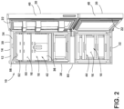
- the open position of the door 20 as illustrated in FIG. 2 , the access to the storage compartment 18 that corresponds with the door 20 is provided.
- a variety of styles of refrigeration units 10 with varying numbers of storage compartments and/or doors are contemplated.
- the refrigerator compartment 42 is positioned nearer than the freezer compartment 44 to the top 30 of the refrigeration unit 10.
- the refrigeration unit 10 is configured as a bottom-freezer refrigeration unit.
- the refrigeration unit 10 includes the cabinet 12.
- the cabinet 12 defines the storage compartment 18 of the refrigeration unit 10.
- the cabinet 12 includes the front perimeter 14.
- the front perimeter 14 can surround the opening 16 to the storage compartment 18 of the refrigeration unit 10.
- the front perimeter 14 of the cabinet 12 defines the opening 16 to the storage compartment 18.
- the cabinet 12 includes an outer wrapper 50 and an inner liner 52.
- the outer wrapper 50 and the inner liner 52 define a cabinet interior 54.
- the cabinet interior 54 is filled at least partially with insulation, such that the refrigeration unit 10 is insulated.
- the cabinet 12 can be insulated via a variety of materials and/or methods.
- the cabinet 12 may include foam insulation, in various embodiments.
- the outer wrapper 50 and the inner liner 52 of the cabinet 12 can cooperate to form the front perimeter 14 of the refrigeration unit 10, as illustrated in FIGS. 3-5 , as described further herein.
- the inner liner 52 includes a first liner side 56 and a second liner side 58 that is opposite the first liner side 56.
- a portion of the first liner side 56 at least partially defines the storage compartment 18 of the refrigeration unit 10.
- a portion of the first liner side 56 of the inner liner 52 defines the storage compartment 18 of the refrigeration unit 10. It is contemplated that one or more other components of the refrigeration unit 10 can define the storage compartment 18 of the refrigeration unit 10 together with the portion of the inner liner 52.
- the inner liner 52 includes a first liner portion 60 and a second liner portion 62. In the embodiments illustrated in FIGS.
- the first liner portion 60 forms the front perimeter 14 of the cabinet 12 together with the outer wrapper 50.
- the first liner side 56 of the first liner portion 60 forms an exterior surface of the front perimeter 14 of the cabinet 12 together with the outer wrapper 50, as described further herein.
- the second liner portion 62 extends from the first liner portion 60 into the cabinet interior 54. In the embodiments illustrated in FIGS. 3-5 , the second liner portion 62 extends from the first liner portion 60 to a terminus 64 that is upward of the first liner portion 60.
- the second liner portion 62 includes a first step portion 66 and a second step portion 68.
- the first step portion 66 is further than the first liner portion 60 of the inner liner 52 from the opening 16 to the storage compartment 18, and the second step portion 68 is further than the first step portion 66 from the opening 16 to the storage compartment 18.
- the first liner side 56 of the first step portion 66 is a first distance from the front perimeter 14 of the cabinet 12
- the first liner side 56 of the second step portion 68 is a second distance from the front perimeter 14 of the cabinet 12, wherein the second distance is greater than the first distance.
- the first liner side 56 of the first step portion 66 can be substantially parallel to the first liner side 56 of the second step portion 68.
- the first liner side 56 of the first step portion 66 is substantially parallel to the first liner side 56 of the second step portion 68
- the first liner side 56 of both the first and second step portions 66, 68 are substantially parallel to the first liner side 56 of the first liner portion 60.
- a portion of the inner liner 52 defines the storage compartment 18 within the cabinet 12, and a portion of the inner liner 52 forms at least a portion of the front perimeter 14 of the cabinet 12.
- the portion of the inner liner 52 that defines the at least a portion of the front perimeter 14 and the portion of the inner liner 52 that defines the storage compartment 18 are coupled to each other at a corner 70.
- the corner 70 defines the opening 16 to the storage compartment 18.
- the portion of the inner liner 52 that defines the storage compartment 18 extends rearward (i.e., generally toward the rear side 36 of the refrigeration unit 10) and storage compartment-outboard from the corner 70 of the inner liner 52 to form a diverter portion 72.
- the diverter portion 72 extends upward and rearward from the corner 70 of the inner liner 52, such that the opening 16 defined by the corner 70 is generally narrower than a parallel space positioned within the storage compartment 18, rearward of the opening 16.
- this is represented by the portion of the inner liner 52 that constitutes a ceiling 74 of the storage compartment 18 being further upward than the corner 70 of the inner liner 52.
- the front perimeter 14 of the cabinet 12 can include a first shelf portion 76 and a second shelf portion 78.
- the second shelf portion 78 is nearer than the first shelf portion 76 to the rear side 36 of the refrigeration unit 10.
- the second shelf portion 78 of the front perimeter 14 is generally recessed relative to the first shelf portion 76 of the front perimeter 14.
- the first shelf portion 76 and the second shelf portion 78 are generally parallel to each other.
- the outer wrapper 50 of the cabinet 12 includes a first wrapper side 80 and a second wrapper side 82 that is opposite the first wrapper side 80.
- the outer wrapper 50 can include a first wrapper portion 84 and a second wrapper portion 86.
- the first wrapper side 80 of the first wrapper portion 84 can form the front perimeter 14 of the cabinet 12 together with the first liner portion 60 of the inner liner 52.
- the second wrapper portion 86 extends from the first wrapper portion 84 into the cabinet interior 54.
- the second wrapper portion 86 includes a retainer 88 that couples the outer wrapper 50 to the inner liner 52. In the embodiments illustrated in FIGS.
- the second wrapper portion 86 of the outer wrapper 50 comprises a retainer 88 that includes a first elongated section 90 that extends from the first wrapper portion 84 to an arcuate section 92 of the retainer 88, a second elongated section 94 that extends outward from the arcuate section 92, and a tang 96 that extends outward from the second elongated section 94 to a retainer terminus 98. It is contemplated that the second wrapper portion 86 of the outer wrapper 50 may form a variety of types of retainers, in various implementations.
- the first wrapper side 80 of the second wrapper portion 86 contacts the first and/or second liner sides 56, 58 of the second liner portion 62.
- the first wrapper side 80 of the first elongated section 90 contacts the first liner side 56 of the second liner portion 62
- the first wrapper side 80 of the second elongated section 94 contacts the second liner side 58 of the second liner portion 62.
- the first wrapper side 80 of the first elongated section 90 of the retainer 88 of the second wrapper portion 86 contactingly extends along the first liner side 56 of the first step portion 66 of the inner liner 52. Further, the first wrapper side 80 of the second elongated section 94 of the retainer 88 of the second wrapper portion 86 contactingly extends along the second liner side 58 of the second step portion 68 of the second liner portion 62 of the inner liner 52.
- the refrigeration unit 10 includes a heat loop conduit 24.
- the heat loop conduit 24 may refer to at least one of a Yoder loop conduit and a pre-condenser loop conduit.
- the heat loop conduit 24 is disposed within the cabinet interior 54 and extends along the front perimeter 14 of the cabinet 12.
- the heat loop conduit 24 can extend around a majority of the opening 16 to the storage compartment 18 along the front perimeter 14 of the cabinet 12. In some implementations, the heat loop conduit 24 extends entirely around the opening 16 to the storage compartment 18 along the front perimeter 14.
- the heat loop conduit 24 may be configured to emit heat which is transferred through the front perimeter 14 of the cabinet 12 to the at least one gasket 22 coupled to the door 20 of the refrigeration unit 10 in the closed position of the door 20 to prevent condensation from freezing on the gasket 22, as described further herein.
- the heat loop conduit 24 includes the first conduit portion 26 and the second conduit portion 28.
- the first and second conduit portions 26, 28 may be adjacent sections of the heat loop conduit 24.
- the first conduit portion 26 and/or the second conduit portion 28 extends around a majority of the opening 16 along the front perimeter 14 of the cabinet 12.
- the heat loop conduit 24 includes the first conduit portion 26 that extends around the opening 16 to the storage compartment 18 along the front perimeter 14 of the cabinet 12, and the second conduit portion 28 that extends around the majority of the opening 16 along the front perimeter 14 of the cabinet 12. It is contemplated that the first and/or second conduit portions 26, 28 may extend entirely around the opening 16 along the front perimeter 14 of the cabinet 12, in some implementations.
- the first and second conduit portions 26, 28 are disposed within the cabinet interior 54, proximate to the front perimeter 14 of the cabinet 12.
- the first conduit portion 26 can extend between the first liner side 56 of the second liner portion 62 and the front perimeter 14 of the cabinet 12.
- the first conduit portion 26 is positioned between the second step portion 68 of the inner liner 52 and the first elongated section 90 of the retainer 88 of the outer wrapper 50.
- the second conduit portion 28 is positioned upward of the first conduit portion 26 within the space defined by the first elongated section 90, the arcuate section 92, and the second elongated section 94 of the retainer 88.
- the refrigeration unit 10 may include a retention clip 100.
- the retention clip 100 may be disposed within the cabinet interior 54 and may be coupled to the first and second conduit portions 26, 28 of the heat loop conduit 24.
- the retention clip 100 extends along the first wrapper side 80 of the arcuate section 92 of the retainer 88, around a majority of the circumference of the second conduit portion 28, along the first wrapper side 80 of the first elongated section 90 of the retainer 88, and around a majority of the circumference of the first conduit portion 26.
- the retention clip 100 may maintain the first and second conduit portions 26, 28 in position relative to each other and/or relative to other components of the refrigeration unit 10.
- At least one gasket 22 is coupled to the door 20 of the refrigeration unit 10.
- the at least one gasket 22 is configured to be compressed between the door 20 and the front perimeter 14 of the cabinet 12 in the closed position of the door 20. Compression of the at least one gasket 22 between the door 20 and the front perimeter 14 of the cabinet 12 is configured to form a seal between the door 20 and the cabinet 12, such that air is generally prevented from entering and exiting the storage compartment 18 via the opening 16 concealed by the door 20 in the closed position. Sealing the opening 16 to the storage compartment 18 in this manner may aid in maintaining the temperature-controlled environment within the storage compartment 18 of the refrigeration unit 10.
- the at least one gasket 22 can be compressed between the door 20 and the first and/or second shelf portions 76, 78 of the front perimeter 14 of the cabinet 12, in some implementations.
- the at least one gasket 22 is compressed between the door 20 and the first shelf portion 76 of the front perimeter 14.
- the at least one gasket 22 includes a plurality of gaskets 22.
- first and second gaskets 22A, 22B are coupled to the door 20.
- the first gasket 22A is configured to be compressed between the door 20 and the first shelf portion 76 of the front perimeter 14 in the closed position of the door 20
- the second gasket 22B is configured to be compressed between the door 20 and the second shelf portion 78 of the front perimeter 14 of the cabinet 12 in the closed position of the door 20.
- the refrigeration unit 10 includes the heat loop conduit 24 having the first and second conduit portions 26, 28, the first and second conduit portions 26, 28 extend within the cabinet interior 54 along the front perimeter 14 of the cabinet 12.
- the first and second conduit portions 26, 28 emit heat that warms the at least one gasket 22 that is compressed between the door 20 and front perimeter 14 of the cabinet 12, such that condensation does not freeze on the gasket 22.
- the door 20 is a vacuum insulated door 20
- the inner liner 52 includes the diverter portion 72.
- the diverter portion 72 of the inner liner 52 is configured to divert air circulating within the storage compartment 18 away from the at least one gasket 22 that is compressed between the front perimeter 14 of the cabinet 12 and the door 20 in the closed position of the door 20.
- FIGS. 1C and 5 an exemplary embodiment of the refrigeration unit 10, wherein the first and second gaskets 22A, 22B are coupled to the door 20, is illustrated.
- the second gasket 22B generally prevents air from within the storage compartment 18 from flowing to the first gasket 22A in the closed position of the door 20. As such, condensation is generally prevented from accumulating and freezing on the first gasket 22A during operation of the refrigeration unit 10.
- a refrigeration unit includes a cabinet that includes a front perimeter that surrounds an opening to a storage compartment within the cabinet and a door coupled to the cabinet and operable between an open position and a closed position. In the open position of the door, access to the storage compartment is provided. In the closed position of the door, the door conceals the opening to the storage compartment.
- the refrigeration unit also includes at least one gasket coupled to the door and configured to be compressed between the door and the front perimeter of the cabinet in the closed position of the door.
- the refrigeration compartment further includes a heat loop conduit having a first conduit portion that extends around a majority of the opening along the front perimeter of the cabinet and a second conduit portion that extends around the majority of the opening along the front perimeter of the cabinet.
- the cabinet includes an outer wrapper and an inner liner coupled to the outer wrapper.
- the inner liner and outer wrapper cooperate to form the front perimeter and define a cabinet interior.
- the first and second conduit portions are positioned within the cabinet interior.
- the inner liner includes a first liner side and a second liner side opposite the first liner side. A portion of the first liner side defines the storage compartment.
- the inner liner includes a first liner portion that forms the front perimeter of the cabinet together with the outer wrapper and a second liner portion that extends from the first liner portion into the cabinet interior.
- the first conduit portion extends between the first liner side of the second liner portion and the front perimeter of the cabinet.
- the outer wrapper includes a first wrapper side and a second wrapper side opposite the first wrapper side.
- the outer wrapper includes a first wrapper portion and a second wrapper portion.
- the first wrapper side of the first wrapper portion forms the front perimeter of the cabinet together with the first liner portion.
- the second wrapper portion extends from the first wrapper portion into the cabinet interior. The first wrapper side of the second wrapper portion contacts the first and second liner sides of the second liner portion.
- a retention clip is coupled to the first conduit portion, the second conduit portion, and the first wrapper side of the second wrapper portion.
- the second liner portion includes a first step portion that is further than the first liner portion from the opening to the storage compartment.
- the first liner side of the first step portion is a first distance from the front perimeter of the cabinet.
- the second liner portion also includes a second step portion that is further than the first step portion from the opening to the storage compartment.
- the first liner side of the second step portion is a second distance from the front perimeter of the cabinet. Further, the second distance is greater than the first distance.
- the first liner side of the first liner portion is substantially parallel to the first liner side of the first step portion and the first liner side of the second step portion.
- the first conduit portion extends between the second step portion and the front perimeter of the cabinet.
- the outer wrapper contacts the second liner side of the second step portion and the first liner side of the first step portion.
- the door is a vacuum insulated door.
- the cabinet is a foam insulated cabinet.
- a refrigeration unit includes a cabinet which includes an outer wrapper and an inner liner coupled to the outer wrapper.
- the inner liner defines a storage compartment within the cabinet and forms at least a portion of a front perimeter of the cabinet.
- the portion of the inner liner that defines the at least a portion of the front perimeter and the portion of the inner liner that defines the storage compartment are coupled to each other at a corner that defines an opening to the storage compartment.
- the portion of the inner liner that defines the storage compartment extends rearward and storage compartment-outboard from the corner of the inner liner to form a diverter portion.
- the refrigeration unit also includes a door coupled to the cabinet and operable between an open position and a closed position. In the open position of the door, access to the storage compartment is provided.
- the refrigeration unit further includes at least one gasket coupled to the door and configured to be compressed between the door and the front perimeter of the cabinet in the closed position of the door.
- the diverter portion of the inner liner is configured to divert air from the storage compartment away from the at least one gasket.
- the front perimeter includes a first shelf portion and a second shelf portion.
- the second shelf portion is nearer than the first shelf portion to a rear side of the cabinet and the at least one gasket is configured to be compressed between the door and the first shelf portion of the front perimeter.
- a heat loop conduit is disposed within a cabinet interior and extends along the front perimeter of the cabinet.
- the door is a vacuum insulated door.
- the cabinet is a foam insulated cabinet.
- a refrigeration unit includes a cabinet that includes a front perimeter that surrounds an opening to a storage compartment within the cabinet.
- the front perimeter includes a first shelf portion and a second shelf portion that defines the opening to the storage compartment and is nearer than the first shelf portion to a rear side of the cabinet.
- the refrigeration unit also includes a door coupled to the cabinet and operable between an open position and a closed position. In the open position of the door, access to the storage compartment is provided. In the closed position of the door, the door conceals the opening to the storage compartment.
- the refrigeration unit further includes a first gasket coupled to the door and configured to be compressed between the door and the first shelf portion of the front perimeter of the cabinet in the closed position of the door, and a second gasket coupled to the door and configured to be compressed between the door and the second shelf portion of the front perimeter of the cabinet in the closed position of the door.
- first and second shelf portions are substantially parallel to each other.
- the term "coupled” in all of its forms, couple, coupling, coupled, etc. generally means the joining of two components (electrical or mechanical) directly or indirectly to one another. Such joining may be stationary in nature or movable in nature. Such joining may be achieved with the two components (electrical or mechanical) and any additional intermediate members being integrally formed as a single unitary body with one another or with the two components. Such joining may be permanent in nature or may be removable or releasable in nature unless otherwise stated.
- elements shown as integrally formed may be constructed of multiple parts or elements shown as multiple parts may be integrally formed, the operation of the interfaces may be reversed or otherwise varied, the length or width of the structures and/or members or connector or other elements of the system may be varied, the nature or number of adjustment positions provided between the elements may be varied.
- the elements and/or assemblies of the system may be constructed from any of a wide variety of materials that provide sufficient strength or durability, in any of a wide variety of colors, textures, and combinations. Accordingly, all such modifications are intended to be included within the scope of the present innovations. Other substitutions, modifications, changes, and omissions may be made in the design, operating conditions, and arrangement of the desired and other exemplary embodiments without departing from the spirit of the present innovations.
Landscapes
- Engineering & Computer Science (AREA)
- Chemical & Material Sciences (AREA)
- Combustion & Propulsion (AREA)
- Physics & Mathematics (AREA)
- Mechanical Engineering (AREA)
- Thermal Sciences (AREA)
- General Engineering & Computer Science (AREA)
- Refrigerator Housings (AREA)
Abstract
Description
- The present disclosure generally relates to a refrigeration unit and, more specifically, to a refrigeration unit having a door and a gasket coupled to the door.
- According to an aspect of the present disclosure, a refrigeration unit includes a cabinet that includes a front perimeter that surrounds an opening to a storage compartment within the cabinet and a door coupled to the cabinet and operable between an open position and a closed position. In the open position of the door, access to the storage compartment is provided. In the closed position of the door, the door conceals the opening to the storage compartment. The refrigeration unit also includes at least one gasket coupled to the door and configured to be compressed between the door and the front perimeter of the cabinet in the closed position of the door. The refrigeration compartment further includes a heat loop conduit having a first conduit portion that extends around a majority of the opening along the front perimeter of the cabinet and a second conduit portion that extends around the majority of the opening along the front perimeter of the cabinet.
- These and other features, advantages, and objects of the present disclosure will be further understood and appreciated by those skilled in the art by reference to the following specification, claims, and appended drawings.
- In the drawings:
-
FIG. 1A is a front elevational view of a refrigeration unit, illustrating a heat loop conduit in phantom; -
FIG. 1B is a front elevational view of a refrigeration unit; -
FIG. 1C is a front elevational view of a refrigeration unit; -
FIG. 2 is a front elevational view of a refrigeration unit illustrating a door of the refrigeration unit in an open position and a storage compartment within the refrigeration unit; -
FIG. 3 is a cross-sectional view of a portion of the refrigeration unit ofFIG. 1A taken at line III-III showing a heat loop conduit proximate to a gasket coupled to a door of the refrigeration unit; -
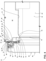
FIG. 4 is a cross-sectional view of a portion of the refrigeration unit ofFIG. 1B taken at line IV-IV showing an inner liner that includes a diverter portion; and -
FIG. 5 is a cross-sectional view of a portion of the refrigeration unit ofFIG. 1C taken at line V-V showing a door and first and second gaskets coupled to the door and compressed between the door and a cabinet of the refrigeration unit. - The components in the figures are not necessarily to scale, emphasis instead being placed upon illustrating the principles described herein.
- The present illustrated embodiments reside primarily in combinations of apparatus components related to a refrigeration unit. Accordingly, the apparatus components have been represented, where appropriate, by conventional symbols in the drawings, showing only those specific details that are pertinent to understanding the embodiments of the present disclosure so as not to obscure the disclosure with details that will be readily apparent to those of ordinary skill in the art having the benefit of the description herein. Further, like numerals in the description and drawings represent like elements.
- For purposes of description herein, the terms "upper," "lower," "right," "left," "rear," "front," "vertical," "horizontal," and derivatives thereof shall relate to the disclosure as oriented in
FIG. 1A . Unless stated otherwise, the term "front" shall refer to the surface of the element closer to an intended viewer, and the term "rear" shall refer to the surface of the element further from the intended viewer. However, it is to be understood that the disclosure may assume various alternative orientations, except where expressly specified to the contrary. It is also to be understood that the specific devices and processes illustrated in the attached drawings and described in the following specification are simply exemplary embodiments of the inventive concepts defined in the appended claims. Hence, specific dimensions and other physical characteristics relating to the embodiments disclosed herein are not to be considered as limiting, unless the claims expressly state otherwise. - The terms "including," "comprises," "comprising," or any other variation thereof, are intended to cover a non-exclusive inclusion, such that a process, method, article, or apparatus that comprises a list of elements does not include only those elements but may include other elements not expressly listed or inherent to such process, method, article, or apparatus. An element proceeded by "comprises a ... " does not, without more constraints, preclude the existence of additional identical elements in the process, method, article, or apparatus that comprises the element.
- Referring now to
FIGS. 1A-5 ,reference 10 generally designates a refrigeration unit. Therefrigeration unit 10 includes acabinet 12 that includes afront perimeter 14 that surrounds anopening 16 to astorage compartment 18 within thecabinet 12. Adoor 20 is coupled to thecabinet 12 and is operable between an open position, wherein access to thestorage compartment 18 is provided, and a closed position, wherein thedoor 20 conceals theopening 16 to thestorage compartment 18. At least onegasket 22 is coupled to thedoor 20 and is configured to be compressed between thedoor 20 and thefront perimeter 14 of thecabinet 12 in the closed position of thedoor 20. Aheat loop conduit 24 includes afirst conduit portion 26 that extends around a majority of the opening 16 along thefront perimeter 14 of thecabinet 12 and asecond conduit portion 28 that extends around the majority of the opening 16 along thefront perimeter 14 of thecabinet 12. - Referring now to
FIGS. 1A-2 , therefrigeration unit 10 includes atop 30 and abottom 32 opposite thetop 30. Afront side 34 and arear side 36 opposite thefront side 34 extend between thetop 30 and thebottom 32. Aright side 40 and aleft side 38 opposite theright side 40 are disposed between the front andrear sides top 30 and thebottom 32. Therefrigeration unit 10 includes at least onestorage compartment 18 in which items are configured to be stored in a temperature-controlled environment. In the embodiments illustrated inFIGS. 1A-2 , therefrigeration unit 10 includes twostorage compartments 18 -- arefrigerator compartment 42 and afreezer compartment 44. Therefrigeration unit 10 further includes at least onedoor 20. In the embodiments illustrated inFIGS. 1A-2 , therefrigeration unit 10 includes twodoors 20 -- arefrigerator compartment door 46 and afreezer compartment door 48. The refrigerator andfreezer compartment doors refrigeration unit 10 proximate to thefront side 34 and are operable between closed and open positions. In the closed position (illustrated inFIGS. 1A-1C ), thedoor 20 conceals the opening 16 to thecorresponding storage compartment 18. In the open position of thedoor 20, as illustrated inFIG. 2 , the access to thestorage compartment 18 that corresponds with thedoor 20 is provided. A variety of styles ofrefrigeration units 10 with varying numbers of storage compartments and/or doors are contemplated. With reference toFIGS. 1A-2 , therefrigerator compartment 42 is positioned nearer than thefreezer compartment 44 to thetop 30 of therefrigeration unit 10. As such, therefrigeration unit 10 is configured as a bottom-freezer refrigeration unit. - Referring now to
FIGS. 2-5 , therefrigeration unit 10 includes thecabinet 12. Thecabinet 12 defines thestorage compartment 18 of therefrigeration unit 10. As illustrated inFIG. 2 , thecabinet 12 includes thefront perimeter 14. Thefront perimeter 14 can surround theopening 16 to thestorage compartment 18 of therefrigeration unit 10. In various implementations, thefront perimeter 14 of thecabinet 12 defines theopening 16 to thestorage compartment 18. - Referring still to
FIGS. 2-5 , thecabinet 12 includes anouter wrapper 50 and aninner liner 52. Theouter wrapper 50 and theinner liner 52 define acabinet interior 54. In various implementations, thecabinet interior 54 is filled at least partially with insulation, such that therefrigeration unit 10 is insulated. Thecabinet 12 can be insulated via a variety of materials and/or methods. For example, thecabinet 12 may include foam insulation, in various embodiments. Theouter wrapper 50 and theinner liner 52 of thecabinet 12 can cooperate to form thefront perimeter 14 of therefrigeration unit 10, as illustrated inFIGS. 3-5 , as described further herein. - Referring now to
FIGS. 3-5 , theinner liner 52 includes afirst liner side 56 and asecond liner side 58 that is opposite thefirst liner side 56. In various embodiments, a portion of thefirst liner side 56 at least partially defines thestorage compartment 18 of therefrigeration unit 10. As illustrated inFIGS. 3-5 , a portion of thefirst liner side 56 of theinner liner 52 defines thestorage compartment 18 of therefrigeration unit 10. It is contemplated that one or more other components of therefrigeration unit 10 can define thestorage compartment 18 of therefrigeration unit 10 together with the portion of theinner liner 52. Theinner liner 52 includes afirst liner portion 60 and asecond liner portion 62. In the embodiments illustrated inFIGS. 3-5 , thefirst liner portion 60 forms thefront perimeter 14 of thecabinet 12 together with theouter wrapper 50. For example, as illustrated inFIG. 3 , thefirst liner side 56 of thefirst liner portion 60 forms an exterior surface of thefront perimeter 14 of thecabinet 12 together with theouter wrapper 50, as described further herein. Thesecond liner portion 62 extends from thefirst liner portion 60 into thecabinet interior 54. In the embodiments illustrated inFIGS. 3-5 , thesecond liner portion 62 extends from thefirst liner portion 60 to aterminus 64 that is upward of thefirst liner portion 60. - Referring now to
FIG. 3 , in some implementations, thesecond liner portion 62 includes afirst step portion 66 and asecond step portion 68. Thefirst step portion 66 is further than thefirst liner portion 60 of theinner liner 52 from theopening 16 to thestorage compartment 18, and thesecond step portion 68 is further than thefirst step portion 66 from theopening 16 to thestorage compartment 18. In various implementations, thefirst liner side 56 of thefirst step portion 66 is a first distance from thefront perimeter 14 of thecabinet 12, and thefirst liner side 56 of thesecond step portion 68 is a second distance from thefront perimeter 14 of thecabinet 12, wherein the second distance is greater than the first distance. Thefirst liner side 56 of thefirst step portion 66 can be substantially parallel to thefirst liner side 56 of thesecond step portion 68. For example, in the embodiment illustrated inFIG. 3 , thefirst liner side 56 of thefirst step portion 66 is substantially parallel to thefirst liner side 56 of thesecond step portion 68, and thefirst liner side 56 of both the first andsecond step portions first liner side 56 of thefirst liner portion 60. - Referring now to
FIG. 4 , in various embodiments, a portion of theinner liner 52 defines thestorage compartment 18 within thecabinet 12, and a portion of theinner liner 52 forms at least a portion of thefront perimeter 14 of thecabinet 12. As illustrated inFIG. 4 , the portion of theinner liner 52 that defines the at least a portion of thefront perimeter 14 and the portion of theinner liner 52 that defines thestorage compartment 18 are coupled to each other at acorner 70. Thecorner 70 defines theopening 16 to thestorage compartment 18. In the embodiment illustrated inFIG. 4 , the portion of theinner liner 52 that defines thestorage compartment 18 extends rearward (i.e., generally toward therear side 36 of the refrigeration unit 10) and storage compartment-outboard from thecorner 70 of theinner liner 52 to form adiverter portion 72. As shown inFIG. 4 , thediverter portion 72 extends upward and rearward from thecorner 70 of theinner liner 52, such that theopening 16 defined by thecorner 70 is generally narrower than a parallel space positioned within thestorage compartment 18, rearward of theopening 16. InFIG. 4 , this is represented by the portion of theinner liner 52 that constitutes aceiling 74 of thestorage compartment 18 being further upward than thecorner 70 of theinner liner 52. - Referring now to
FIGS. 4 and5 , thefront perimeter 14 of thecabinet 12 can include afirst shelf portion 76 and asecond shelf portion 78. In various implementations, thesecond shelf portion 78 is nearer than thefirst shelf portion 76 to therear side 36 of therefrigeration unit 10. For example, as illustrated inFIGS. 4 and5 , thesecond shelf portion 78 of thefront perimeter 14 is generally recessed relative to thefirst shelf portion 76 of thefront perimeter 14. Further, in the illustrated embodiments, thefirst shelf portion 76 and thesecond shelf portion 78 are generally parallel to each other. - Referring now to
FIGS. 2-5 , theouter wrapper 50 of thecabinet 12 includes afirst wrapper side 80 and asecond wrapper side 82 that is opposite thefirst wrapper side 80. As illustrated inFIGS. 3-5 , theouter wrapper 50 can include afirst wrapper portion 84 and asecond wrapper portion 86. Thefirst wrapper side 80 of thefirst wrapper portion 84 can form thefront perimeter 14 of thecabinet 12 together with thefirst liner portion 60 of theinner liner 52. Thesecond wrapper portion 86 extends from thefirst wrapper portion 84 into thecabinet interior 54. In various implementations, thesecond wrapper portion 86 includes aretainer 88 that couples theouter wrapper 50 to theinner liner 52. In the embodiments illustrated inFIGS. 3-5 , thesecond wrapper portion 86 of theouter wrapper 50 comprises aretainer 88 that includes a firstelongated section 90 that extends from thefirst wrapper portion 84 to anarcuate section 92 of theretainer 88, a secondelongated section 94 that extends outward from thearcuate section 92, and atang 96 that extends outward from the secondelongated section 94 to aretainer terminus 98. It is contemplated that thesecond wrapper portion 86 of theouter wrapper 50 may form a variety of types of retainers, in various implementations. - Referring now to
FIGS. 3-5 , in some implementations, thefirst wrapper side 80 of thesecond wrapper portion 86 contacts the first and/or second liner sides 56, 58 of thesecond liner portion 62. For example, as illustrated inFIGS. 4 and5 , thefirst wrapper side 80 of the firstelongated section 90 contacts thefirst liner side 56 of thesecond liner portion 62, and thefirst wrapper side 80 of the secondelongated section 94 contacts thesecond liner side 58 of thesecond liner portion 62. In the embodiment illustrated inFIG. 3 , thefirst wrapper side 80 of the firstelongated section 90 of theretainer 88 of thesecond wrapper portion 86 contactingly extends along thefirst liner side 56 of thefirst step portion 66 of theinner liner 52. Further, thefirst wrapper side 80 of the secondelongated section 94 of theretainer 88 of thesecond wrapper portion 86 contactingly extends along thesecond liner side 58 of thesecond step portion 68 of thesecond liner portion 62 of theinner liner 52. - Referring now to
FIGS. 1A and3-5 , therefrigeration unit 10 includes aheat loop conduit 24. As used herein, theheat loop conduit 24 may refer to at least one of a Yoder loop conduit and a pre-condenser loop conduit. Theheat loop conduit 24 is disposed within thecabinet interior 54 and extends along thefront perimeter 14 of thecabinet 12. Theheat loop conduit 24 can extend around a majority of theopening 16 to thestorage compartment 18 along thefront perimeter 14 of thecabinet 12. In some implementations, theheat loop conduit 24 extends entirely around theopening 16 to thestorage compartment 18 along thefront perimeter 14. In operation of therefrigeration unit 10, theheat loop conduit 24 may be configured to emit heat which is transferred through thefront perimeter 14 of thecabinet 12 to the at least onegasket 22 coupled to thedoor 20 of therefrigeration unit 10 in the closed position of thedoor 20 to prevent condensation from freezing on thegasket 22, as described further herein. - Referring now to
FIGS. 1A and3 , in some implementations, theheat loop conduit 24 includes thefirst conduit portion 26 and thesecond conduit portion 28. The first andsecond conduit portions heat loop conduit 24. In various implementations, thefirst conduit portion 26 and/or thesecond conduit portion 28 extends around a majority of theopening 16 along thefront perimeter 14 of thecabinet 12. For example, as illustrated inFIG. 1A , theheat loop conduit 24 includes thefirst conduit portion 26 that extends around theopening 16 to thestorage compartment 18 along thefront perimeter 14 of thecabinet 12, and thesecond conduit portion 28 that extends around the majority of theopening 16 along thefront perimeter 14 of thecabinet 12. It is contemplated that the first and/orsecond conduit portions opening 16 along thefront perimeter 14 of thecabinet 12, in some implementations. - As illustrated in
FIG. 3 , the first andsecond conduit portions cabinet interior 54, proximate to thefront perimeter 14 of thecabinet 12. Thefirst conduit portion 26 can extend between thefirst liner side 56 of thesecond liner portion 62 and thefront perimeter 14 of thecabinet 12. For example, in the embodiment illustrated inFIG. 3 , thefirst conduit portion 26 is positioned between thesecond step portion 68 of theinner liner 52 and the firstelongated section 90 of theretainer 88 of theouter wrapper 50. Further, thesecond conduit portion 28 is positioned upward of thefirst conduit portion 26 within the space defined by the firstelongated section 90, thearcuate section 92, and the secondelongated section 94 of theretainer 88. - Referring still to
FIG. 3 , therefrigeration unit 10 may include aretention clip 100. Theretention clip 100 may be disposed within thecabinet interior 54 and may be coupled to the first andsecond conduit portions heat loop conduit 24. In the embodiment illustrated inFIG. 3 , theretention clip 100 extends along thefirst wrapper side 80 of thearcuate section 92 of theretainer 88, around a majority of the circumference of thesecond conduit portion 28, along thefirst wrapper side 80 of the firstelongated section 90 of theretainer 88, and around a majority of the circumference of thefirst conduit portion 26. Theretention clip 100 may maintain the first andsecond conduit portions refrigeration unit 10. - Referring now to
FIGS. 3-5 , at least onegasket 22 is coupled to thedoor 20 of therefrigeration unit 10. The at least onegasket 22 is configured to be compressed between thedoor 20 and thefront perimeter 14 of thecabinet 12 in the closed position of thedoor 20. Compression of the at least onegasket 22 between thedoor 20 and thefront perimeter 14 of thecabinet 12 is configured to form a seal between thedoor 20 and thecabinet 12, such that air is generally prevented from entering and exiting thestorage compartment 18 via theopening 16 concealed by thedoor 20 in the closed position. Sealing theopening 16 to thestorage compartment 18 in this manner may aid in maintaining the temperature-controlled environment within thestorage compartment 18 of therefrigeration unit 10. - The at least one
gasket 22 can be compressed between thedoor 20 and the first and/orsecond shelf portions front perimeter 14 of thecabinet 12, in some implementations. For example, as illustrated inFIG. 4 , the at least onegasket 22 is compressed between thedoor 20 and thefirst shelf portion 76 of thefront perimeter 14. In some implementations, the at least onegasket 22 includes a plurality ofgaskets 22. For example, in the embodiment illustrated inFIG. 5 , first andsecond gaskets door 20. In the illustrated embodiment, thefirst gasket 22A is configured to be compressed between thedoor 20 and thefirst shelf portion 76 of thefront perimeter 14 in the closed position of thedoor 20, and thesecond gasket 22B is configured to be compressed between thedoor 20 and thesecond shelf portion 78 of thefront perimeter 14 of thecabinet 12 in the closed position of thedoor 20. - Referring now to
FIGS. 1A and3 , in operation of an exemplary embodiment of therefrigeration unit 10, wherein therefrigeration unit 10 includes theheat loop conduit 24 having the first andsecond conduit portions second conduit portions cabinet interior 54 along thefront perimeter 14 of thecabinet 12. The first andsecond conduit portions gasket 22 that is compressed between thedoor 20 andfront perimeter 14 of thecabinet 12, such that condensation does not freeze on thegasket 22. - Referring now to
FIGS. 1B and4 , an exemplary embodiment of therefrigeration unit 10 is illustrated, wherein thedoor 20 is a vacuum insulateddoor 20, and theinner liner 52 includes thediverter portion 72. Thediverter portion 72 of theinner liner 52 is configured to divert air circulating within thestorage compartment 18 away from the at least onegasket 22 that is compressed between thefront perimeter 14 of thecabinet 12 and thedoor 20 in the closed position of thedoor 20. - Referring now to
FIGS. 1C and5 , an exemplary embodiment of therefrigeration unit 10, wherein the first andsecond gaskets door 20, is illustrated. In operation of the exemplary embodiment, thesecond gasket 22B generally prevents air from within thestorage compartment 18 from flowing to thefirst gasket 22A in the closed position of thedoor 20. As such, condensation is generally prevented from accumulating and freezing on thefirst gasket 22A during operation of therefrigeration unit 10. - According to one aspect of the present disclosure, a refrigeration unit includes a cabinet that includes a front perimeter that surrounds an opening to a storage compartment within the cabinet and a door coupled to the cabinet and operable between an open position and a closed position. In the open position of the door, access to the storage compartment is provided. In the closed position of the door, the door conceals the opening to the storage compartment. The refrigeration unit also includes at least one gasket coupled to the door and configured to be compressed between the door and the front perimeter of the cabinet in the closed position of the door. The refrigeration compartment further includes a heat loop conduit having a first conduit portion that extends around a majority of the opening along the front perimeter of the cabinet and a second conduit portion that extends around the majority of the opening along the front perimeter of the cabinet.
- According to another aspect, the cabinet includes an outer wrapper and an inner liner coupled to the outer wrapper. The inner liner and outer wrapper cooperate to form the front perimeter and define a cabinet interior. The first and second conduit portions are positioned within the cabinet interior.
- According to another aspect, the inner liner includes a first liner side and a second liner side opposite the first liner side. A portion of the first liner side defines the storage compartment.
- According to another aspect, the inner liner includes a first liner portion that forms the front perimeter of the cabinet together with the outer wrapper and a second liner portion that extends from the first liner portion into the cabinet interior. The first conduit portion extends between the first liner side of the second liner portion and the front perimeter of the cabinet.
- According to another aspect, the outer wrapper includes a first wrapper side and a second wrapper side opposite the first wrapper side.
- According to another aspect, the outer wrapper includes a first wrapper portion and a second wrapper portion. The first wrapper side of the first wrapper portion forms the front perimeter of the cabinet together with the first liner portion. The second wrapper portion extends from the first wrapper portion into the cabinet interior. The first wrapper side of the second wrapper portion contacts the first and second liner sides of the second liner portion.
- According to another aspect, a retention clip is coupled to the first conduit portion, the second conduit portion, and the first wrapper side of the second wrapper portion.
- According to another aspect, the second liner portion includes a first step portion that is further than the first liner portion from the opening to the storage compartment. The first liner side of the first step portion is a first distance from the front perimeter of the cabinet. The second liner portion also includes a second step portion that is further than the first step portion from the opening to the storage compartment. The first liner side of the second step portion is a second distance from the front perimeter of the cabinet. Further, the second distance is greater than the first distance.
- According to another aspect, the first liner side of the first liner portion is substantially parallel to the first liner side of the first step portion and the first liner side of the second step portion.
- According to another aspect, the first conduit portion extends between the second step portion and the front perimeter of the cabinet.
- According to another aspect, the outer wrapper contacts the second liner side of the second step portion and the first liner side of the first step portion.
- According to another aspect, the door is a vacuum insulated door.
- According to yet another aspect, the cabinet is a foam insulated cabinet.
- According to another aspect, a refrigeration unit includes a cabinet which includes an outer wrapper and an inner liner coupled to the outer wrapper. The inner liner defines a storage compartment within the cabinet and forms at least a portion of a front perimeter of the cabinet. The portion of the inner liner that defines the at least a portion of the front perimeter and the portion of the inner liner that defines the storage compartment are coupled to each other at a corner that defines an opening to the storage compartment. The portion of the inner liner that defines the storage compartment extends rearward and storage compartment-outboard from the corner of the inner liner to form a diverter portion. The refrigeration unit also includes a door coupled to the cabinet and operable between an open position and a closed position. In the open position of the door, access to the storage compartment is provided. In the closed position of the door, the door conceals the opening to the storage compartment. The refrigeration unit further includes at least one gasket coupled to the door and configured to be compressed between the door and the front perimeter of the cabinet in the closed position of the door. The diverter portion of the inner liner is configured to divert air from the storage compartment away from the at least one gasket.
- According to another aspect, the front perimeter includes a first shelf portion and a second shelf portion. The second shelf portion is nearer than the first shelf portion to a rear side of the cabinet and the at least one gasket is configured to be compressed between the door and the first shelf portion of the front perimeter.
- According to another aspect, a heat loop conduit is disposed within a cabinet interior and extends along the front perimeter of the cabinet.
- According to another aspect, the door is a vacuum insulated door.
- According to yet another aspect, the cabinet is a foam insulated cabinet.
- According to another aspect, a refrigeration unit includes a cabinet that includes a front perimeter that surrounds an opening to a storage compartment within the cabinet. The front perimeter includes a first shelf portion and a second shelf portion that defines the opening to the storage compartment and is nearer than the first shelf portion to a rear side of the cabinet. The refrigeration unit also includes a door coupled to the cabinet and operable between an open position and a closed position. In the open position of the door, access to the storage compartment is provided. In the closed position of the door, the door conceals the opening to the storage compartment. The refrigeration unit further includes a first gasket coupled to the door and configured to be compressed between the door and the first shelf portion of the front perimeter of the cabinet in the closed position of the door, and a second gasket coupled to the door and configured to be compressed between the door and the second shelf portion of the front perimeter of the cabinet in the closed position of the door.
- According to another aspect, the first and second shelf portions are substantially parallel to each other.
- It will be understood by one having ordinary skill in the art that construction of the described disclosure and other components is not limited to any specific material. Other exemplary embodiments of the disclosure disclosed herein may be formed from a wide variety of materials, unless described otherwise herein.
- For purposes of this disclosure, the term "coupled" (in all of its forms, couple, coupling, coupled, etc.) generally means the joining of two components (electrical or mechanical) directly or indirectly to one another. Such joining may be stationary in nature or movable in nature. Such joining may be achieved with the two components (electrical or mechanical) and any additional intermediate members being integrally formed as a single unitary body with one another or with the two components. Such joining may be permanent in nature or may be removable or releasable in nature unless otherwise stated.
- It is also important to note that the construction and arrangement of the elements of the disclosure as shown in the exemplary embodiments is illustrative only. Although only a few embodiments of the present innovations have been described in detail in this disclosure, those skilled in the art who review this disclosure will readily appreciate that many modifications are possible (e.g., variations in sizes, dimensions, structures, shapes and proportions of the various elements, values of parameters, mounting arrangements, use of materials, colors, orientations, etc.) without materially departing from the novel teachings and advantages of the subject matter recited. For example, elements shown as integrally formed may be constructed of multiple parts or elements shown as multiple parts may be integrally formed, the operation of the interfaces may be reversed or otherwise varied, the length or width of the structures and/or members or connector or other elements of the system may be varied, the nature or number of adjustment positions provided between the elements may be varied. It should be noted that the elements and/or assemblies of the system may be constructed from any of a wide variety of materials that provide sufficient strength or durability, in any of a wide variety of colors, textures, and combinations. Accordingly, all such modifications are intended to be included within the scope of the present innovations. Other substitutions, modifications, changes, and omissions may be made in the design, operating conditions, and arrangement of the desired and other exemplary embodiments without departing from the spirit of the present innovations.
- It will be understood that any described processes or steps within described processes may be combined with other disclosed processes or steps to form structures within the scope of the present disclosure. The exemplary structures and processes disclosed herein are for illustrative purposes and are not to be construed as limiting.
Claims (15)
- A refrigeration unit (10), comprising:a cabinet (12) that includes a front perimeter (14) that surrounds an opening (16) to a storage compartment (18) within the cabinet (12);a door (20) coupled to the cabinet (12) and operable between an open position, wherein access to the storage compartment (18) is provided, and a closed position, wherein the door (20) conceals the opening (16) to the storage compartment (18);at least one gasket (22) coupled to the door (20) and configured to be compressed between the door (20) and the front perimeter (14) of the cabinet (12) in the closed position of the door (20); anda heat loop conduit (24) having a first conduit portion (26) that extends around a majority of the opening (16) along the front perimeter (14) of the cabinet (12) and a second conduit portion (28) that extends around the majority of the opening (16) along the front perimeter (14) of the cabinet (12).
- The refrigeration unit (10) of claim 1, wherein the cabinet (12) comprises:an outer wrapper (50); andan inner liner (52) coupled to the outer wrapper (50), wherein the inner liner (52) and outer wrapper (50) cooperate to form the front perimeter (14) and define a cabinet interior (54), wherein the first and second conduit portions (26, 28) are positioned within the cabinet interior (54).
- The refrigeration unit (10) of claim 2, wherein the inner liner (52) defines the storage compartment (18) within the cabinet (12), wherein a portion of the inner liner (52) that defines the front perimeter (14) and a portion of the inner liner (52) that defines the storage compartment (18) are coupled to each other at a corner (70) that defines the opening (16) to the storage compartment (18), and wherein the portion of the inner liner (52) that defines the storage compartment (18) extends rearward and storage compartment-outboard from the corner (70) of the inner liner (52) to form a diverter portion (72).
- The refrigeration unit (10) of claim 3, wherein the diverter portion (72) of the inner liner (52) is configured to divert air from the storage compartment (18) away from the at least one gasket (22).
- The refrigeration unit (10) of claim 2, wherein the inner liner (52) comprises:a first liner side (56); anda second liner side (58) opposite the first liner side (56), wherein a portion of the first liner side (56) defines the storage compartment (18).
- The refrigeration unit (10) of claim 5, wherein the inner liner (52) comprises:a first liner portion (60) that forms the front perimeter (14) of the cabinet (12) together with the outer wrapper (50); anda second liner portion (62) that extends from the first liner portion (60) into the cabinet interior (54), wherein the first conduit portion (26) extends between the first liner side (56) of the second liner portion (62) and the front perimeter (14) of the cabinet (12).
- The refrigeration unit (10) of claim 6, wherein the outer wrapper (50) comprises:a first wrapper side (80); anda second wrapper side (82) opposite the first wrapper side (80).
- The refrigeration unit (10) of claim 7, wherein the outer wrapper (50) comprises:a first wrapper portion (84), wherein the first wrapper side (80) of the first wrapper portion (84) forms the front perimeter (14) of the cabinet (12) together with the first liner portion (60); anda second wrapper portion (86) that extends from the first wrapper portion (84) into the cabinet interior (54), wherein the first wrapper side (80) of the second wrapper portion (86) contacts the first and second liner sides (56, 58) of the second liner portion (62).
- The refrigeration unit (10) of claim 8, further comprising:
a retention clip (100) that is coupled to the first conduit portion (26), the second conduit portion (28), and the first wrapper side (80) of the second wrapper portion (86). - The refrigeration unit (10) of any one of claims 6-9, wherein the second liner portion (62) comprises:a first step portion (66) that is further than the first liner portion (60) from the opening (16) to the storage compartment (18), wherein the first liner side (56) of the first step portion (66) is a first distance from the front perimeter (14) of the cabinet (12); anda second step portion (68) that is further than the first step portion (66) from the opening (16) to the storage compartment (18), wherein the first liner side (56) of the second step portion (68) is a second distance from the front perimeter (14) of the cabinet (12), wherein the second distance is greater than the first distance.
- The refrigeration unit (10) of claim 10, wherein the first liner side (56) of the first liner portion (60) is substantially parallel to the first liner side (56) of the first step portion (66) and the first liner side (56) of the second step portion (68).
- The refrigeration unit (10) of either of claim 10 or 11, wherein the first conduit portion (26) extends between the second step portion (68) and the front perimeter (14) of the cabinet (12).
- The refrigeration unit (10) of any one of claims 10-12, wherein the outer wrapper (50) contacts the second liner side (58) of the second step portion (68) and the first liner side (56) of the first step portion (66).
- The refrigeration unit (10) of any one of claims 1-13, wherein the door (20) is a vacuum insulated door (20).
- The refrigeration unit (10) of any one of claims 1-14, wherein the cabinet (12) is a foam insulated cabinet (12).
Applications Claiming Priority (1)
| Application Number | Priority Date | Filing Date | Title |
|---|---|---|---|
| US17/668,728 US11859895B2 (en) | 2022-02-10 | 2022-02-10 | Refrigeration unit |
Publications (1)
| Publication Number | Publication Date |
|---|---|
| EP4227617A1 true EP4227617A1 (en) | 2023-08-16 |
Family
ID=85018032
Family Applications (1)
| Application Number | Title | Priority Date | Filing Date |
|---|---|---|---|
| EP23152554.4A Withdrawn EP4227617A1 (en) | 2022-02-10 | 2023-01-19 | Refrigeration unit |
Country Status (2)
| Country | Link |
|---|---|
| US (1) | US11859895B2 (en) |
| EP (1) | EP4227617A1 (en) |
Families Citing this family (3)
| Publication number | Priority date | Publication date | Assignee | Title |
|---|---|---|---|---|
| WO2024145594A2 (en) * | 2022-12-30 | 2024-07-04 | True Manufacturing Co., Inc. | Gasket for refrigerated cabinet |
| EP4643065A2 (en) * | 2022-12-30 | 2025-11-05 | True Manufacturing Co., Inc. | Refrigerated cabinet |
| US20250341359A1 (en) * | 2024-05-03 | 2025-11-06 | Whirlpool Corporation | Trim breaker profile for a vacuum insulated structure |
Citations (4)
| Publication number | Priority date | Publication date | Assignee | Title |
|---|---|---|---|---|
| US2135091A (en) * | 1936-01-22 | 1938-11-01 | Gen Motors Corp | Refrigerating apparatus |
| CN108027194A (en) * | 2015-10-15 | 2018-05-11 | 三星电子株式会社 | Refrigerator |
| US20180299060A1 (en) * | 2015-10-19 | 2018-10-18 | Samsung Electromics Co., Ltd. | Refrigerator and manufacturing method therefor |
| US20200103161A1 (en) * | 2017-03-30 | 2020-04-02 | Samsung Electronics Co., Ltd. | Refrigerator |
Family Cites Families (16)
| Publication number | Priority date | Publication date | Assignee | Title |
|---|---|---|---|---|
| US1980005A (en) * | 1930-02-12 | 1934-11-06 | Seeger Refrigerator Co | Refrigerator closure |
| US2247949A (en) * | 1936-09-24 | 1941-07-01 | Andrew A Kucher | Refrigerating apparatus |
| US4114065A (en) * | 1976-12-09 | 1978-09-12 | General Electric Company | Refrigerator cabinet and method of constructing |
| US4891912A (en) | 1987-07-07 | 1990-01-09 | Ardco, Inc. | Refrigerator door assembly with multiple gasket sealing arrangement |
| US5297360A (en) * | 1992-08-20 | 1994-03-29 | General Electric Company | Refrigerator cabinet with combination sealing arrangement |
| KR20000020955A (en) | 1998-09-24 | 2000-04-15 | 구자홍 | Structure for arranging condenser tube of refrigerator |
| KR20030085305A (en) | 2002-04-30 | 2003-11-05 | 엘지전자 주식회사 | Refrigerator door |
| KR100564970B1 (en) * | 2003-11-26 | 2006-03-28 | 엘지전자 주식회사 | Refrigerator sealing structure |
| KR100678663B1 (en) | 2004-10-20 | 2007-02-06 | 삼성전자주식회사 | Refrigerator with cold air leak prevention device |
| KR100761155B1 (en) * | 2006-04-28 | 2007-10-04 | 엘지전자 주식회사 | Kimchi refrigerator inner case |
| KR101622602B1 (en) | 2009-02-24 | 2016-05-20 | 엘지전자 주식회사 | Refrigerator having dewfall preventing member |
| KR20140047360A (en) | 2012-10-12 | 2014-04-22 | 동부대우전자 주식회사 | Refrigerator for preventing coagulation of door gasket |
| JP6905856B2 (en) * | 2017-05-10 | 2021-07-21 | パナソニック株式会社 | refrigerator |
| JPWO2019225690A1 (en) * | 2018-05-25 | 2021-02-12 | Phcホールディングス株式会社 | Sealed structure of cooling device and cooling device |
| US10563905B1 (en) * | 2018-09-13 | 2020-02-18 | Whirlpool Corporation | Ferromagnetic cover for a trim breaker of an appliance cabinet |
| AT522200A1 (en) * | 2019-02-07 | 2020-09-15 | Rep Ip Ag | Transport container |
-
2022
- 2022-02-10 US US17/668,728 patent/US11859895B2/en active Active
-
2023
- 2023-01-19 EP EP23152554.4A patent/EP4227617A1/en not_active Withdrawn
Patent Citations (4)
| Publication number | Priority date | Publication date | Assignee | Title |
|---|---|---|---|---|
| US2135091A (en) * | 1936-01-22 | 1938-11-01 | Gen Motors Corp | Refrigerating apparatus |
| CN108027194A (en) * | 2015-10-15 | 2018-05-11 | 三星电子株式会社 | Refrigerator |
| US20180299060A1 (en) * | 2015-10-19 | 2018-10-18 | Samsung Electromics Co., Ltd. | Refrigerator and manufacturing method therefor |
| US20200103161A1 (en) * | 2017-03-30 | 2020-04-02 | Samsung Electronics Co., Ltd. | Refrigerator |
Also Published As
| Publication number | Publication date |
|---|---|
| US11859895B2 (en) | 2024-01-02 |
| US20230251026A1 (en) | 2023-08-10 |
Similar Documents
| Publication | Publication Date | Title |
|---|---|---|
| US11859895B2 (en) | Refrigeration unit | |
| US6428130B1 (en) | Refrigerator mullion | |
| US11662136B2 (en) | Appliance hinge assembly | |
| EP2719979A1 (en) | Refrigerator for preventing dewing on door gasket | |
| US20180259244A1 (en) | Refrigerator | |
| US11732954B2 (en) | Refrigeration appliance cabinet assembly | |
| CN113623929A (en) | Appliance door gasket assembly | |
| US20230314065A1 (en) | Appliance trim breaker | |
| US20250044016A1 (en) | Support system for a vacuum insulated panel | |
| JP2008075934A (en) | refrigerator | |
| US20130293081A1 (en) | Cabinet gasket for refrigerator | |
| US12442590B2 (en) | Refrigeration appliance with a refrigerant line and water line extending through common pass-through of a vacuum-insulated structure | |
| US11971210B2 (en) | Appliance encapsulation member | |
| CN100587372C (en) | Low-temperature storage | |
| US12535260B2 (en) | Trimbreaker ladder cover | |
| US20250341359A1 (en) | Trim breaker profile for a vacuum insulated structure | |
| JP6716012B2 (en) | refrigerator | |
| JP7755939B2 (en) | refrigerator | |
| JPH10288455A (en) | Refrigerator with vegetable room | |
| JP6782394B2 (en) | refrigerator | |
| KR100499026B1 (en) | Refrigerator | |
| CN119334032A (en) | Refrigeration equipment with door protrusions to reduce heat transfer at the interface between the door and the cabinet | |
| JP2001033149A (en) | refrigerator | |
| KR200363129Y1 (en) | Lamp gasket in a show case | |
| JP7038274B2 (en) | refrigerator |
Legal Events
| Date | Code | Title | Description |
|---|---|---|---|
| PUAI | Public reference made under article 153(3) epc to a published international application that has entered the european phase |
Free format text: ORIGINAL CODE: 0009012 |
|
| STAA | Information on the status of an ep patent application or granted ep patent |
Free format text: STATUS: THE APPLICATION HAS BEEN PUBLISHED |
|
| AK | Designated contracting states |
Kind code of ref document: A1 Designated state(s): AL AT BE BG CH CY CZ DE DK EE ES FI FR GB GR HR HU IE IS IT LI LT LU LV MC ME MK MT NL NO PL PT RO RS SE SI SK SM TR |
|
| STAA | Information on the status of an ep patent application or granted ep patent |
Free format text: STATUS: REQUEST FOR EXAMINATION WAS MADE |
|
| 17P | Request for examination filed |
Effective date: 20240216 |
|
| RBV | Designated contracting states (corrected) |
Designated state(s): AL AT BE BG CH CY CZ DE DK EE ES FI FR GB GR HR HU IE IS IT LI LT LU LV MC ME MK MT NL NO PL PT RO RS SE SI SK SM TR |
|
| STAA | Information on the status of an ep patent application or granted ep patent |
Free format text: STATUS: THE APPLICATION HAS BEEN WITHDRAWN |
|
| 18W | Application withdrawn |
Effective date: 20250428 |