EP4227545A1 - Stud assembly - Google Patents
Stud assembly Download PDFInfo
- Publication number
- EP4227545A1 EP4227545A1 EP23156015.2A EP23156015A EP4227545A1 EP 4227545 A1 EP4227545 A1 EP 4227545A1 EP 23156015 A EP23156015 A EP 23156015A EP 4227545 A1 EP4227545 A1 EP 4227545A1
- Authority
- EP
- European Patent Office
- Prior art keywords
- stud
- rivet
- cavity
- neck
- sphere
- Prior art date
- Legal status (The legal status is an assumption and is not a legal conclusion. Google has not performed a legal analysis and makes no representation as to the accuracy of the status listed.)
- Granted
Links
Images







Classifications
-
- F—MECHANICAL ENGINEERING; LIGHTING; HEATING; WEAPONS; BLASTING
- F16—ENGINEERING ELEMENTS AND UNITS; GENERAL MEASURES FOR PRODUCING AND MAINTAINING EFFECTIVE FUNCTIONING OF MACHINES OR INSTALLATIONS; THERMAL INSULATION IN GENERAL
- F16B—DEVICES FOR FASTENING OR SECURING CONSTRUCTIONAL ELEMENTS OR MACHINE PARTS TOGETHER, e.g. NAILS, BOLTS, CIRCLIPS, CLAMPS, CLIPS OR WEDGES; JOINTS OR JOINTING
- F16B19/00—Bolts without screw-thread; Pins, including deformable elements; Rivets
- F16B19/04—Rivets; Spigots or the like fastened by riveting
- F16B19/08—Hollow rivets; Multi-part rivets
- F16B19/10—Hollow rivets; Multi-part rivets fastened by expanding mechanically
- F16B19/1027—Multi-part rivets
- F16B19/1036—Blind rivets
- F16B19/1081—Blind rivets fastened by a drive-pin
-
- F—MECHANICAL ENGINEERING; LIGHTING; HEATING; WEAPONS; BLASTING
- F16—ENGINEERING ELEMENTS AND UNITS; GENERAL MEASURES FOR PRODUCING AND MAINTAINING EFFECTIVE FUNCTIONING OF MACHINES OR INSTALLATIONS; THERMAL INSULATION IN GENERAL
- F16B—DEVICES FOR FASTENING OR SECURING CONSTRUCTIONAL ELEMENTS OR MACHINE PARTS TOGETHER, e.g. NAILS, BOLTS, CIRCLIPS, CLAMPS, CLIPS OR WEDGES; JOINTS OR JOINTING
- F16B19/00—Bolts without screw-thread; Pins, including deformable elements; Rivets
- F16B19/04—Rivets; Spigots or the like fastened by riveting
- F16B19/06—Solid rivets made in one piece
-
- H—ELECTRICITY
- H01—ELECTRIC ELEMENTS
- H01R—ELECTRICALLY-CONDUCTIVE CONNECTIONS; STRUCTURAL ASSOCIATIONS OF A PLURALITY OF MUTUALLY-INSULATED ELECTRICAL CONNECTING ELEMENTS; COUPLING DEVICES; CURRENT COLLECTORS
- H01R4/00—Electrically-conductive connections between two or more conductive members in direct contact, i.e. touching one another; Means for effecting or maintaining such contact; Electrically-conductive connections having two or more spaced connecting locations for conductors and using contact members penetrating insulation
- H01R4/28—Clamped connections, spring connections
- H01R4/50—Clamped connections, spring connections utilising a cam, wedge, cone or ball also combined with a screw
-
- F—MECHANICAL ENGINEERING; LIGHTING; HEATING; WEAPONS; BLASTING
- F16—ENGINEERING ELEMENTS AND UNITS; GENERAL MEASURES FOR PRODUCING AND MAINTAINING EFFECTIVE FUNCTIONING OF MACHINES OR INSTALLATIONS; THERMAL INSULATION IN GENERAL
- F16B—DEVICES FOR FASTENING OR SECURING CONSTRUCTIONAL ELEMENTS OR MACHINE PARTS TOGETHER, e.g. NAILS, BOLTS, CIRCLIPS, CLAMPS, CLIPS OR WEDGES; JOINTS OR JOINTING
- F16B37/00—Nuts or like thread-engaging members
- F16B37/04—Devices for fastening nuts to surfaces, e.g. sheets, plates
- F16B37/06—Devices for fastening nuts to surfaces, e.g. sheets, plates by means of welding or riveting
- F16B37/062—Devices for fastening nuts to surfaces, e.g. sheets, plates by means of welding or riveting by means of riveting
- F16B37/064—Devices for fastening nuts to surfaces, e.g. sheets, plates by means of welding or riveting by means of riveting with the use of separate rivets
-
- F—MECHANICAL ENGINEERING; LIGHTING; HEATING; WEAPONS; BLASTING
- F16—ENGINEERING ELEMENTS AND UNITS; GENERAL MEASURES FOR PRODUCING AND MAINTAINING EFFECTIVE FUNCTIONING OF MACHINES OR INSTALLATIONS; THERMAL INSULATION IN GENERAL
- F16B—DEVICES FOR FASTENING OR SECURING CONSTRUCTIONAL ELEMENTS OR MACHINE PARTS TOGETHER, e.g. NAILS, BOLTS, CIRCLIPS, CLAMPS, CLIPS OR WEDGES; JOINTS OR JOINTING
- F16B5/00—Joining sheets or plates, e.g. panels, to one another or to strips or bars parallel to them
- F16B5/04—Joining sheets or plates, e.g. panels, to one another or to strips or bars parallel to them by means of riveting
-
- H—ELECTRICITY
- H01—ELECTRIC ELEMENTS
- H01H—ELECTRIC SWITCHES; RELAYS; SELECTORS; EMERGENCY PROTECTIVE DEVICES
- H01H11/00—Apparatus or processes specially adapted for the manufacture of electric switches
- H01H11/04—Apparatus or processes specially adapted for the manufacture of electric switches of switch contacts
- H01H11/041—Apparatus or processes specially adapted for the manufacture of electric switches of switch contacts by bonding of a contact marking face to a contact body portion
- H01H11/042—Apparatus or processes specially adapted for the manufacture of electric switches of switch contacts by bonding of a contact marking face to a contact body portion by mechanical deformation
-
- H—ELECTRICITY
- H01—ELECTRIC ELEMENTS
- H01R—ELECTRICALLY-CONDUCTIVE CONNECTIONS; STRUCTURAL ASSOCIATIONS OF A PLURALITY OF MUTUALLY-INSULATED ELECTRICAL CONNECTING ELEMENTS; COUPLING DEVICES; CURRENT COLLECTORS
- H01R4/00—Electrically-conductive connections between two or more conductive members in direct contact, i.e. touching one another; Means for effecting or maintaining such contact; Electrically-conductive connections having two or more spaced connecting locations for conductors and using contact members penetrating insulation
- H01R4/58—Electrically-conductive connections between two or more conductive members in direct contact, i.e. touching one another; Means for effecting or maintaining such contact; Electrically-conductive connections having two or more spaced connecting locations for conductors and using contact members penetrating insulation characterised by the form or material of the contacting members
-
- F—MECHANICAL ENGINEERING; LIGHTING; HEATING; WEAPONS; BLASTING
- F16—ENGINEERING ELEMENTS AND UNITS; GENERAL MEASURES FOR PRODUCING AND MAINTAINING EFFECTIVE FUNCTIONING OF MACHINES OR INSTALLATIONS; THERMAL INSULATION IN GENERAL
- F16B—DEVICES FOR FASTENING OR SECURING CONSTRUCTIONAL ELEMENTS OR MACHINE PARTS TOGETHER, e.g. NAILS, BOLTS, CIRCLIPS, CLAMPS, CLIPS OR WEDGES; JOINTS OR JOINTING
- F16B2200/00—Constructional details of connections not covered for in other groups of this subclass
- F16B2200/93—Fastener comprising feature for establishing a good electrical connection, e.g. electrostatic discharge or insulation feature
-
- H—ELECTRICITY
- H01—ELECTRIC ELEMENTS
- H01H—ELECTRIC SWITCHES; RELAYS; SELECTORS; EMERGENCY PROTECTIVE DEVICES
- H01H11/00—Apparatus or processes specially adapted for the manufacture of electric switches
- H01H11/04—Apparatus or processes specially adapted for the manufacture of electric switches of switch contacts
- H01H11/06—Fixing of contacts to carrier ; Fixing of contacts to insulating carrier
- H01H2011/067—Fixing of contacts to carrier ; Fixing of contacts to insulating carrier by deforming, e.g. bending, folding or caulking, part of the contact or terminal which is being mounted
-
- H—ELECTRICITY
- H01—ELECTRIC ELEMENTS
- H01H—ELECTRIC SWITCHES; RELAYS; SELECTORS; EMERGENCY PROTECTIVE DEVICES
- H01H50/00—Details of electromagnetic relays
- H01H50/54—Contact arrangements
Definitions
- Embodiments of the present disclosure relate to devices having electrically conductive studs and, more particularly, to studs supporting high amperage current.
- a variety of electrical devices such as fuse assemblies and switches, use studs to secure the device to another device.
- a battery disconnect switch for example, would include a stud, threaded at one end, to screw the disconnect switch to the battery being protected. One end of the stud is secured by screwing threaded end into a mating cavity of the battery while the other end of the stud is connected to internal circuitry, such as a bus bar, by brazing the stud to the circuitry.
- the studs are part of the current path passing through the electrical device.
- the studs are thus electrical contacts which support the rated amperage of the device.
- the part of the stud that is brazed to the internal circuitry may become disconnected when currents are very high, which limits the current rating of the electrical device containing the stud.
- An exemplary embodiment of a stud assembly in accordance with the present disclosure may include a stud, a sphere, and a rivet.
- the stud has a cylindrical cavity
- the sphere is sized to fit in the cylindrical cavity
- the rivet has a pad and a neck, where the neck is sized to fit in the cylindrical cavity.
- the sphere is inserted into the cylindrical cavity, the neck is partially inserted into the cylindrical cavity, and the pad of the rivet is press-fit until the neck partially deforms against the sphere inside the cylindrical cavity.
- Another exemplary embodiment of a method of assembling a stud assembly in accordance with the present disclosure may include inserting a sphere into a cavity of a stud, where the cavity is cylindrical in shape, inserting a neck of a rivet into the cavity until the neck touches the sphere, and press-fitting the rivet into the cavity until the neck melds with the sphere.
- a stud assembly disclosed herein includes a stud, a rivet, and a sphere.
- the stud has a cylindrical cavity that is sized to receive both the sphere and the rivet.
- the rivet has a neck and a pad, where the neck fits into the cavity and the pad is press-fit into a contact surface of the stud.
- the rivet is bi-metallic, with the neck made of a first metal and the pad made of a second metal.
- the sphere is made of a third metal which is harder than the first and second metals. When press-fit into the cavity, the neck of the rivet deforms against the sphere, causing permanent attachment of the rivet to the stud cavity.
- the stud assembly is assembled without brazing operations and is rated to withstand a current up to 500 Amps or more.
- FIGs. 1A and 1B are representative drawings of a stud assembly 100 for use in an electrical device, according to exemplary embodiments.
- FIG. 1A is a perspective view of the stud assembly 100 in a disassembled state while FIG. 1B is a perspective view of the fully assembled stud assembly.
- the stud assembly 100 is capable of withstanding currents of up to 500 amps or more.
- the stud assembly 100 features a stud 116, a rivet 108, and a sphere 114.
- the sphere 114 is inserted into a cavity 118 of the stud 116, after which the rivet 108 is also inserted into the cavity.
- the rivet 108 is to be press-fit into the stud 116 without additional welding or brazing operations and the sphere 114 facilitates establishing a good electrical connection between the stud 116 and the rivet 108.
- the stud 116 includes a threaded portion 102, a contact surface 104, and a contact 106.
- the threaded portion 102 of the stud 116 is substantially cylindrical, with the threads being sized to be mated with a bolt or screwed into a threaded cylindrical opening.
- the threaded portion 102 surrounds the cylindrical cavity 118.
- the contact surface 104 is orthogonal to the threaded portion 102 and includes the contact 106.
- the contact 106 and cavity 118 are a unitary part of the stud 116.
- the stud 116 including the threaded portion 102 and the contact surface 104, is made of copper, with the threaded portion, the contact surface, the contact 106, and the cavity 118 being made of copper which is also silver-plated.
- the cavity 118 is a blind hole in the contact 106, with suitable depth and diameter for receiving the sphere 114 and the neck 110 of the rivet 108.
- the rivet 108 is a bi-metallic device including a neck 110 made of a first metal and a pad 112 made of a second metal, with the first metal being different from the second metal.
- the neck 110 is orthogonal to the pad 112.
- the neck 110 a copper or copper alloy while the pad 112 is silver.
- the rivet 108 is silver plated, in exemplary embodiments, with the pad 112 of the rivet being 99.98% silver.
- the sphere 114 is made of a material that is harder/less malleable than that of the neck 110. In some embodiments, the sphere 114 is made of stainless steel, which is harder than copper or silver.
- the rivet 108 fits into the cavity 118 of the stud 116 such that the pad 112 is flush against the contact 106.
- the sphere 114 is inserted into the cavity 118 before inserting the rivet 108.
- the rivet 108 is inserted into the cavity 118 by press-fitting, in exemplary embodiments. Once press-fit into the cavity 118 of the stud 116, the rivet 108 is not removable, in exemplary embodiments, and the stud 116 can withstand up to 500 Amps of current without the rivet 108 being disjoined from the stud.
- the sphere 114 helps the rivet 108 to be connected to the inner surface of the stud 116, thus ensuring a good electrical connection therebetween.
- FIG. 2 is a representative drawing of the rivet 108 of the stud assembly 100 of FIGs. 1A and 1B , according to exemplary embodiments.
- a seat 202 is shown at the portion of the neck 110 not connected to the pad 112.
- the seat 202 is bowl-shaped and sized to fit against the sphere 114.
- the seat 202 will fit snugly against the sphere 114.
- the sphere 114 is made of a material that is harder than the neck 110 of the rivet 108, the neck 110 will partially deform around the sphere 114, as illustrated in further detail below.
- FIGs. 3A-3D are representative drawings of the stud assembly 100 of FIGs. 1A and 1B , according to exemplary embodiments.
- the figures illustrate the stud assembly 100 in various stages of construction, with FIG. 3A showing a first stage, FIG. 3B showing a second stage, FIG. 3C showing a third stage, and FIG. 3D showing a fourth stage.
- FIGs. 3A-3D thus provide a step-by-step illustration of how the rivet 108 is mated with the stud 116.
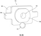
- FIG. 3A is a perspective view of the stud 116, featuring the contact surface 104 while the threaded portion 102 is mostly obscured.
- the contact surface 104 includes the contact 106 and the cavity 118.
- the cavity 118 is a cylindrical structure with a diameter, d 3 , that is slightly larger than 1) the diameter, d 1 , of the neck 110 of the rivet 108 and 2) the diameter, d 2 , of the sphere 114.
- the cavity 118 is thus sized to receive both the sphere 114 and the neck 110 of the rivet 108.
- the walls of the cavity 118 are made from the same material as the contact 106, silver plated copper or copper alloy.
- the sphere 114 is not inserted into the cavity 118.
- FIG. 3B again shows the stud 116, this time with the sphere 114 inserted into the cavity 118.
- the second stage of the stud assembly 100 involves inserting the sphere 114 into the cavity 118.
- the third stage of the stud assembly 100 involves inserting the rivet 108 into the cavity 118.
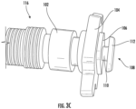
- the neck 110 of the rivet 108 is partially inserted into the cavity 118.
- the pad 112 of the rivet 108 is not yet touching the contact 106 of the stud 116.
- FIG. 3D is also a side perspective view of the stud 116.
- the rivet 108 is fully inserted into the cavity 118, with the neck 110 of the rivet no longer being visible and the pad 112 of the rivet being flush against the contact 106 of the stud 116.
- the rivet 108 is partially inserted into the cavity 118 of the stud 116 until the neck 110 of the rivet touches the sphere 114 (third stage), then the neck partially surrounds the sphere once the rivet is press-fit into the cavity (fourth stage).
- FIG. 4 is a representative drawing of the stud assembly 100, according to exemplary embodiments.
- the side cross-sectional view of the stud 116 shows that the neck 110 of the rivet 108 is deformed against an inside surface 402 of the cavity 118.
- a join region 404 shows where the neck 110 of the rivet 108 mates with the sphere 114. Because the rivet 108 is made of a softer material than the sphere 114, there is some deformation of the neck 110 of the rivet against the sphere 114, in exemplary embodiments. In exemplary embodiments, at the join region 404, the diameter of the rivet 108 expands such that the rivet 108 will not come out of the cavity 118.
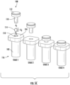
- FIGs. 5A-5C are representative drawings of the stud assembly 100, according to exemplary embodiments. Each figure shows the stud assembly 100 in four stages of construction: FIG. 5A are side cross-sectional views; FIG. 5B are perspective cross-sectional views; and FIG. 5C are perspective views. Reference numbers for each element of the stud assembly 100 are shown in the first stage.
- the threaded portion 102 of the stud 116 is disposed vertically with the contact surface 104 being orthogonal thereto.
- the cavity 118 is a cylindrical opening in the stud 116, centrally disposed through the contact surface 104 and partially into the threaded portion 102.
- the cavity 118 has a tapered end 502 at one end, where the tapered end is the part of the cavity to seat the sphere 114.
- the sphere 114 is positioned over the cavity 118 of the stud 116 and the rivet 108 is positioned over the sphere, as the rivet is meant to be inserted into the cavity after the sphere occupies the cavity.
- the sphere 114 is inserted into the cavity 118 until seated at the tapered end 502 of the cavity.
- the rivet 108 is inserted into the cavity.
- the pad 112 of the rivet 108 is not yet flush against the contact surface 104, as the rivet has been inserted but not yet press-fit into the cavity 118.
- the neck 110 of the rivet 108 is in the cavity 118 with the seat 202 of the rivet ( FIG. 2 ) being disposed over the sphere 114 (stage 3).
- the rivet 108 is press-fit into the cavity 118.
- the pressure of the press-fit operation, as well as the relative softness of the rivet 108 as compared to the sphere 114, causes the neck 110 of the rivet to meld and become partially deformed around the sphere, thus filling any opening of the cavity 118.
- the neck 110 thus fills into available space inside the cavity 118.
- the use of a material for the rivet 108 that is slightly more malleable than that of the sphere 114 enable the neck 110 of the rivet to partially deform over the sphere.
- the neck 110 of the rivet 108 has a first diameter, d 1
- the sphere 114 has a second diameter, d 2
- the cavity 118 has a third diameter, d 3 .
- the diameters, d 1 and d 2 are substantially equal and the diameter, d 3 , is slightly larger than or the same as the diameters, d 1 and d 2 . Stated mathematically, d 1 ⁇ d 2 ⁇ d 3 .
- the rivet 108 is not removable.
- the rivet 108 is thus permanently affixed to the stud 116 without use of additional adhesives such as epoxy or the use of operations such as welding or brazing.
- FIGs. 6A-6B are representative drawings of the stud assembly 100, according to exemplary embodiments.
- FIG. 6A is a side cross-sectional view of the third stage of the stud assembly 100 and
- FIG. 6B is a close-up view of the cavity 118 of the stud 116 during the third stage.
- the rivet 108 is also inserted into the cavity, such that a portion of the neck 110 occupies the cavity.
- the top of the neck 110 is a distance, d 4 , from the contact surface 104.
- the rivet 108 is press-fit into the cavity 118, in exemplary embodiments.
- FIG. 6A is a side cross-sectional view of the third stage of the stud assembly 100
- FIG. 6B is a close-up view of the cavity 118 of the stud 116 during the third stage.
- the sphere 114 is inserted into the cavity 118 and seated at the tapered end 502 and the neck 110 of the rivet 108 is partially inserted into the cavity. Before press-fitting, there is space in the cavity 118 between the sphere 114 and the rivet 108.
- FIGs. 7A and 7B are representative drawings of the stud assembly 100, according to exemplary embodiments.
- FIG. 7A is a side cross-sectional view of the fourth stage of the stud assembly 100 and
- FIG. 7B is a close-up view of the cavity 118 of the stud 116 during the fourth stage.
- the rivet 108 is press-fit into the cavity 118 of the stud 116. This causes the neck 110 of the rivet 108 to deform against the sphere 114.
- FIG. 7A a portion of the sphere 114 is obscured by the neck 110 of the rivet 108.
- the deformation of the neck 110 causes the rivet to cover about half the sphere 114.
- the rivet 108 When surrounding part of the sphere 114, the rivet 108 fills in any gaps of the cavity 118, as shown in FIG. 7B .
- a pressure-induced coupling of the neck 110 of the rivet 108 to the sphere 114 results from the press-fitting, in exemplary embodiments.
- the stud assembly 100 can withstand a high amperage of current.
- Legacy stud assemblies may join the rivet to the stud using brazing operations. Brazing is a process in which metals are joined by melting a filler metal into the joint to create strong permanent bonds. The alloys used for brazing melt at lower temperatures than copper. Brass or silver may be used to ensure that electrical conductivity is maintained between the rivet and the stud. Legacy stud assemblies that employ brazing are not able to receive current higher than about 250 Amps.
- the stud assembly 100 can receive current as high as 500 Amps or more.
- the stud assembly 100 can receive current as high as 2000 Amps for up to ten seconds.
- the maximum transmissible amperage is limited only by the voltage drop between the stud 116 and the rivet 108, which heat up the system.
- the stud assembly 100 withstands high temperatures better than legacy studs that use brazing. Further, the stud assembly 100 is manufactured in less time and at a lower cost than stud assemblies that employ brazing, in some embodiments.
- the stud assembly 100 may be used in circuitry, such as battery disconnect switches, that is rated to receive 500 Amps of current.
Landscapes
- Engineering & Computer Science (AREA)
- General Engineering & Computer Science (AREA)
- Mechanical Engineering (AREA)
- Manufacturing & Machinery (AREA)
- Insertion Pins And Rivets (AREA)
- Pivots And Pivotal Connections (AREA)
Abstract
Description
- Embodiments of the present disclosure relate to devices having electrically conductive studs and, more particularly, to studs supporting high amperage current.
- A variety of electrical devices, such as fuse assemblies and switches, use studs to secure the device to another device. A battery disconnect switch, for example, would include a stud, threaded at one end, to screw the disconnect switch to the battery being protected. One end of the stud is secured by screwing threaded end into a mating cavity of the battery while the other end of the stud is connected to internal circuitry, such as a bus bar, by brazing the stud to the circuitry.
- In some cases, the studs are part of the current path passing through the electrical device. The studs are thus electrical contacts which support the rated amperage of the device. The part of the stud that is brazed to the internal circuitry may become disconnected when currents are very high, which limits the current rating of the electrical device containing the stud.
- It is with respect to these and other considerations that the present improvements may be useful.
- This Summary is provided to introduce a selection of concepts in a simplified form that are further described below in the Detailed Description. This Summary is not intended to identify key or essential features of the claimed subject matter, nor is it intended as an aid in determining the scope of the claimed subject matter.
- An exemplary embodiment of a stud assembly in accordance with the present disclosure may include a stud, a sphere, and a rivet. The stud has a cylindrical cavity, the sphere is sized to fit in the cylindrical cavity, and the rivet has a pad and a neck, where the neck is sized to fit in the cylindrical cavity. The sphere is inserted into the cylindrical cavity, the neck is partially inserted into the cylindrical cavity, and the pad of the rivet is press-fit until the neck partially deforms against the sphere inside the cylindrical cavity.
- Another exemplary embodiment of a method of assembling a stud assembly in accordance with the present disclosure may include inserting a sphere into a cavity of a stud, where the cavity is cylindrical in shape, inserting a neck of a rivet into the cavity until the neck touches the sphere, and press-fitting the rivet into the cavity until the neck melds with the sphere.
-
-
FIGs. 1A-1B are diagrams illustrating a stud assembly, in accordance with exemplary embodiments; -
FIG. 2 is a diagram illustrating a rivet used by the stud assembly ofFIGs. 1A-1B , in accordance with exemplary embodiments; -
FIGs. 3A-3D are diagrams illustrating a method of constructing the stud assembly ofFIGs. 1A-1B , in accordance with exemplary embodiments; -
FIG. 4 is a diagram illustrating the stud assembly ofFIGs. 1A-1B , in accordance with exemplary embodiments; -
FIGs. 5A-5C are diagrams illustrating the steps for constructing the stud assembly ofFIGs. 1A-1B , in accordance with exemplary embodiments; -
FIGs. 6A-6B are diagrams illustrating a stage of constructing the stud assembly ofFIGs. 1A-1B , in accordance with exemplary embodiments; and -
FIGs. 7A-7B are diagrams illustrating a stage of constructing the stud assembly ofFIGs. 1A-1B , in accordance with exemplary embodiments. - A stud assembly disclosed herein includes a stud, a rivet, and a sphere. The stud has a cylindrical cavity that is sized to receive both the sphere and the rivet. The rivet has a neck and a pad, where the neck fits into the cavity and the pad is press-fit into a contact surface of the stud. The rivet is bi-metallic, with the neck made of a first metal and the pad made of a second metal. The sphere is made of a third metal which is harder than the first and second metals. When press-fit into the cavity, the neck of the rivet deforms against the sphere, causing permanent attachment of the rivet to the stud cavity. The stud assembly is assembled without brazing operations and is rated to withstand a current up to 500 Amps or more.
- For the sake of convenience and clarity, terms such as "top", "bottom", "upper", "lower", "vertical", "horizontal", "lateral", "transverse", "radial", "inner", "outer", "left", and "right" may be used herein to describe the relative placement and orientation of the features and components, each with respect to the geometry and orientation of other features and components appearing in the perspective, exploded perspective, and cross-sectional views provided herein. Said terminology is not intended to be limiting and includes the words specifically mentioned, derivatives therein, and words of similar import.
-
FIGs. 1A and 1B are representative drawings of astud assembly 100 for use in an electrical device, according to exemplary embodiments.FIG. 1A is a perspective view of thestud assembly 100 in a disassembled state whileFIG. 1B is a perspective view of the fully assembled stud assembly. In exemplary embodiments, thestud assembly 100 is capable of withstanding currents of up to 500 amps or more. Thestud assembly 100 features astud 116, arivet 108, and asphere 114. In exemplary embodiments, thesphere 114 is inserted into acavity 118 of thestud 116, after which therivet 108 is also inserted into the cavity. As will be shown, therivet 108 is to be press-fit into thestud 116 without additional welding or brazing operations and thesphere 114 facilitates establishing a good electrical connection between thestud 116 and therivet 108. - The
stud 116 includes a threadedportion 102, acontact surface 104, and acontact 106. The threadedportion 102 of thestud 116 is substantially cylindrical, with the threads being sized to be mated with a bolt or screwed into a threaded cylindrical opening. The threadedportion 102 surrounds thecylindrical cavity 118. Thecontact surface 104 is orthogonal to the threadedportion 102 and includes thecontact 106. In exemplary embodiments, thecontact 106 andcavity 118 are a unitary part of thestud 116. In exemplary embodiments, thestud 116, including the threadedportion 102 and thecontact surface 104, is made of copper, with the threaded portion, the contact surface, thecontact 106, and thecavity 118 being made of copper which is also silver-plated. Thecavity 118 is a blind hole in thecontact 106, with suitable depth and diameter for receiving thesphere 114 and theneck 110 of therivet 108. - In exemplary embodiments, the
rivet 108 is a bi-metallic device including aneck 110 made of a first metal and apad 112 made of a second metal, with the first metal being different from the second metal. Theneck 110 is orthogonal to thepad 112. In exemplary embodiments, the neck 110 a copper or copper alloy while thepad 112 is silver. Like thecontact 106, therivet 108 is silver plated, in exemplary embodiments, with thepad 112 of the rivet being 99.98% silver. - In exemplary embodiments, the
sphere 114 is made of a material that is harder/less malleable than that of theneck 110. In some embodiments, thesphere 114 is made of stainless steel, which is harder than copper or silver. - As shown in
FIG. 1B , therivet 108 fits into thecavity 118 of thestud 116 such that thepad 112 is flush against thecontact 106. In exemplary embodiments, thesphere 114 is inserted into thecavity 118 before inserting therivet 108. Further, therivet 108 is inserted into thecavity 118 by press-fitting, in exemplary embodiments. Once press-fit into thecavity 118 of thestud 116, therivet 108 is not removable, in exemplary embodiments, and thestud 116 can withstand up to 500 Amps of current without therivet 108 being disjoined from the stud. As will be shown, thesphere 114 helps therivet 108 to be connected to the inner surface of thestud 116, thus ensuring a good electrical connection therebetween. -
FIG. 2 is a representative drawing of therivet 108 of thestud assembly 100 ofFIGs. 1A and 1B , according to exemplary embodiments. In the perspective view, aseat 202 is shown at the portion of theneck 110 not connected to thepad 112. Theseat 202 is bowl-shaped and sized to fit against thesphere 114. In exemplary embodiments, when therivet 108 is press-fit into thecavity 118 of thestud 116, theseat 202 will fit snugly against thesphere 114. Further, because thesphere 114 is made of a material that is harder than theneck 110 of therivet 108, theneck 110 will partially deform around thesphere 114, as illustrated in further detail below. -
FIGs. 3A-3D are representative drawings of thestud assembly 100 ofFIGs. 1A and 1B , according to exemplary embodiments. The figures illustrate thestud assembly 100 in various stages of construction, withFIG. 3A showing a first stage,FIG. 3B showing a second stage,FIG. 3C showing a third stage, andFIG. 3D showing a fourth stage.FIGs. 3A-3D thus provide a step-by-step illustration of how therivet 108 is mated with thestud 116. -
FIG. 3A , is a perspective view of thestud 116, featuring thecontact surface 104 while the threadedportion 102 is mostly obscured. Thecontact surface 104 includes thecontact 106 and thecavity 118. In exemplary embodiments, thecavity 118 is a cylindrical structure with a diameter, d3, that is slightly larger than 1) the diameter, d1, of theneck 110 of therivet 108 and 2) the diameter, d2 , of thesphere 114. Thecavity 118 is thus sized to receive both thesphere 114 and theneck 110 of therivet 108. In exemplary embodiments, the walls of thecavity 118 are made from the same material as thecontact 106, silver plated copper or copper alloy. At the stage ofFIG. 3A , thesphere 114 is not inserted into thecavity 118. -
FIG. 3B again shows thestud 116, this time with thesphere 114 inserted into thecavity 118. Thus, the second stage of thestud assembly 100 involves inserting thesphere 114 into thecavity 118. The third stage of thestud assembly 100 involves inserting therivet 108 into thecavity 118. In the side perspective view ofFIG. 3C , theneck 110 of therivet 108 is partially inserted into thecavity 118. At the third stage, thepad 112 of therivet 108 is not yet touching thecontact 106 of thestud 116. -
FIG. 3D is also a side perspective view of thestud 116. At the final stage, therivet 108 is fully inserted into thecavity 118, with theneck 110 of the rivet no longer being visible and thepad 112 of the rivet being flush against thecontact 106 of thestud 116. In exemplary embodiments, therivet 108 is partially inserted into thecavity 118 of thestud 116 until theneck 110 of the rivet touches the sphere 114 (third stage), then the neck partially surrounds the sphere once the rivet is press-fit into the cavity (fourth stage). -
FIG. 4 is a representative drawing of thestud assembly 100, according to exemplary embodiments. The side cross-sectional view of thestud 116 shows that theneck 110 of therivet 108 is deformed against aninside surface 402 of thecavity 118. Ajoin region 404 shows where theneck 110 of therivet 108 mates with thesphere 114. Because therivet 108 is made of a softer material than thesphere 114, there is some deformation of theneck 110 of the rivet against thesphere 114, in exemplary embodiments. In exemplary embodiments, at thejoin region 404, the diameter of therivet 108 expands such that therivet 108 will not come out of thecavity 118. -
FIGs. 5A-5C are representative drawings of thestud assembly 100, according to exemplary embodiments. Each figure shows thestud assembly 100 in four stages of construction:FIG. 5A are side cross-sectional views;FIG. 5B are perspective cross-sectional views; andFIG. 5C are perspective views. Reference numbers for each element of thestud assembly 100 are shown in the first stage. The threadedportion 102 of thestud 116 is disposed vertically with thecontact surface 104 being orthogonal thereto. Thecavity 118 is a cylindrical opening in thestud 116, centrally disposed through thecontact surface 104 and partially into the threadedportion 102. In exemplary embodiments, thecavity 118 has atapered end 502 at one end, where the tapered end is the part of the cavity to seat thesphere 114. - At the first stage, the
sphere 114 is positioned over thecavity 118 of thestud 116 and therivet 108 is positioned over the sphere, as the rivet is meant to be inserted into the cavity after the sphere occupies the cavity. At the second stage, thesphere 114 is inserted into thecavity 118 until seated at thetapered end 502 of the cavity. At the third stage, therivet 108 is inserted into the cavity. Thepad 112 of therivet 108 is not yet flush against thecontact surface 104, as the rivet has been inserted but not yet press-fit into thecavity 118. Theneck 110 of therivet 108 is in thecavity 118 with theseat 202 of the rivet (FIG. 2 ) being disposed over the sphere 114 (stage 3). At the fourth stage, therivet 108 is press-fit into thecavity 118. The pressure of the press-fit operation, as well as the relative softness of therivet 108 as compared to thesphere 114, causes theneck 110 of the rivet to meld and become partially deformed around the sphere, thus filling any opening of thecavity 118. As illustrated particularly inFIGs. 5A and5B (stage 4), theneck 110 thus fills into available space inside thecavity 118. The use of a material for therivet 108 that is slightly more malleable than that of thesphere 114 enable theneck 110 of the rivet to partially deform over the sphere. - The
neck 110 of therivet 108 has a first diameter, d1, thesphere 114 has a second diameter, d2 , and thecavity 118 has a third diameter, d3. In exemplary embodiments, the diameters, d1 and d2 are substantially equal and the diameter, d3, is slightly larger than or the same as the diameters, d1 and d2. Stated mathematically, d1 ≅ d2 ≤ d3. These dimensions ensure that both thesphere 114 and theneck 110 of therivet 108 fit inside thecavity 118. - In exemplary embodiments, once the
rivet 108 is press-fit into thestud 116, the rivet is not removable. Therivet 108 is thus permanently affixed to thestud 116 without use of additional adhesives such as epoxy or the use of operations such as welding or brazing. -
FIGs. 6A-6B are representative drawings of thestud assembly 100, according to exemplary embodiments.FIG. 6A is a side cross-sectional view of the third stage of thestud assembly 100 andFIG. 6B is a close-up view of thecavity 118 of thestud 116 during the third stage. As explained above, once thesphere 114 is inserted into thecavity 118, therivet 108 is also inserted into the cavity, such that a portion of theneck 110 occupies the cavity. At the third stage, the top of theneck 110 is a distance, d4 , from thecontact surface 104. Once pressure is applied to thepad 112, therivet 108 is press-fit into thecavity 118, in exemplary embodiments. In the close-up ofFIG. 6B , thesphere 114 is inserted into thecavity 118 and seated at thetapered end 502 and theneck 110 of therivet 108 is partially inserted into the cavity. Before press-fitting, there is space in thecavity 118 between thesphere 114 and therivet 108. -
FIGs. 7A and 7B are representative drawings of thestud assembly 100, according to exemplary embodiments.FIG. 7A is a side cross-sectional view of the fourth stage of thestud assembly 100 andFIG. 7B is a close-up view of thecavity 118 of thestud 116 during the fourth stage. In the fourth stage, therivet 108 is press-fit into thecavity 118 of thestud 116. This causes theneck 110 of therivet 108 to deform against thesphere 114. InFIG. 7A , a portion of thesphere 114 is obscured by theneck 110 of therivet 108. In exemplary embodiments, the deformation of theneck 110 causes the rivet to cover about half thesphere 114. When surrounding part of thesphere 114, therivet 108 fills in any gaps of thecavity 118, as shown inFIG. 7B . Thus, a pressure-induced coupling of theneck 110 of therivet 108 to thesphere 114 results from the press-fitting, in exemplary embodiments. - In contrast to legacy stud assemblies, the
stud assembly 100 can withstand a high amperage of current. Legacy stud assemblies may join the rivet to the stud using brazing operations. Brazing is a process in which metals are joined by melting a filler metal into the joint to create strong permanent bonds. The alloys used for brazing melt at lower temperatures than copper. Brass or silver may be used to ensure that electrical conductivity is maintained between the rivet and the stud. Legacy stud assemblies that employ brazing are not able to receive current higher than about 250 Amps. - The
stud assembly 100, by contrast, can receive current as high as 500 Amps or more. In one embodiment, thestud assembly 100 can receive current as high as 2000 Amps for up to ten seconds. The maximum transmissible amperage is limited only by the voltage drop between thestud 116 and therivet 108, which heat up the system. Thestud assembly 100 withstands high temperatures better than legacy studs that use brazing. Further, thestud assembly 100 is manufactured in less time and at a lower cost than stud assemblies that employ brazing, in some embodiments. In exemplary embodiments, thestud assembly 100 may be used in circuitry, such as battery disconnect switches, that is rated to receive 500 Amps of current. - As used herein, an element or step recited in the singular and proceeded with the word "a" or "an" should be understood as not excluding plural elements or steps, unless such exclusion is explicitly recited. Furthermore, references to "one embodiment" of the present disclosure are not intended to be interpreted as excluding the existence of additional embodiments that also incorporate the recited features.
- While the present disclosure makes reference to certain embodiments, numerous modifications, alterations and changes to the described embodiments are possible without departing from the sphere and scope of the present disclosure, as defined in the appended claim(s). Accordingly, it is intended that the present disclosure not be limited to the described embodiments, but that it has the full scope defined by the language of the following claims, and equivalents thereof.
Claims (15)
- A stud assembly comprising:a stud having a cylindrical cavity formed therein;a sphere to be inserted into the cylindrical cavity; anda rivet comprising a pad and a neck extending orthogonally from the pad, wherein the neck is disposed within the cylindrical cavity and terminates in an end that abuts, and is deformed by, the sphere.
- The stud assembly of claim 1, the stud further comprising a threaded portion, to surround the cylindrical cavity, and a contact surface, wherein the contact surface is orthogonal to the threaded portion and the rivet engages with the contact surface.
- The stud assembly of claim 2, the contact surface further comprising a contact, the contact being part of the contact surface but made of a different material than the contact surface.
- The stud assembly of claims 2 or 3, wherein the contact is made of copper and/or wherein the contact is silver-plated.
- The stud assembly of any of the preceding claims with one or more of the following:• wherein the pad is silver and the neck is copper;• wherein the rivet is not removable once press-fit into the cylindrical cavity of the stud;• wherein the stud can withstand up to 500 Amps of current without the rivet being disjoined from the stud.
- The stud assembly of any of the preceding claims, the rivet further comprising a seat, wherein the pad is disposed at a first end of the neck and the seat is disposed at a second, opposite end of the neck, preferably wherein the seat is bowl-shaped and sized to fit over the sphere.
- The stud assembly of any of the preceding claims, the cylindrical cavity further comprising a tapered end, wherein the sphere is disposed at the tapered end once inserted into the cylindrical cavity.
- The stud assembly of any of the preceding claims, wherein the rivet and the stud are electrically conductive.
- A method of assembling a stud assembly comprising:inserting a sphere into a cavity of a stud, the cavity being cylindrical shaped;inserting a neck of a rivet into the cavity until the neck touches the sphere; andpress-fitting the rivet into the cavity until the neck deforms against the sphere.
- The method of claim 9, the rivet further comprising a pad, wherein the pad does not contact the stud until the rivet is press-fit into the cavity.
- The method of claim 9 or 10, wherein the neck is made of a first metal.
- The method of any of the claims 9-11, wherein the sphere is made of a second metal.
- The method of claim 12, wherein the second metal is harder than the first metal.
- The method of claims 9 or 10, wherein the rivet is bi-metallic, with the neck being made of a first metal and the pad being made of a second metal.
- The method of any of the claims 9-14, wherein the rivet and the stud are electrically conductive and/or wherein the pad is silver and the neck is copper.
Applications Claiming Priority (1)
| Application Number | Priority Date | Filing Date | Title |
|---|---|---|---|
| US17/669,518 US20230258217A1 (en) | 2022-02-11 | 2022-02-11 | Stud assembly |
Publications (2)
| Publication Number | Publication Date |
|---|---|
| EP4227545A1 true EP4227545A1 (en) | 2023-08-16 |
| EP4227545B1 EP4227545B1 (en) | 2025-10-22 |
Family
ID=85225313
Family Applications (1)
| Application Number | Title | Priority Date | Filing Date |
|---|---|---|---|
| EP23156015.2A Active EP4227545B1 (en) | 2022-02-11 | 2023-02-10 | Stud assembly |
Country Status (3)
| Country | Link |
|---|---|
| US (1) | US20230258217A1 (en) |
| EP (1) | EP4227545B1 (en) |
| CN (1) | CN116598800A (en) |
Citations (3)
| Publication number | Priority date | Publication date | Assignee | Title |
|---|---|---|---|---|
| US2234346A (en) * | 1938-03-23 | 1941-03-11 | Clifford E Ives | Circuit breaker |
| FR2680600A3 (en) * | 1991-08-22 | 1993-02-26 | Bosch Gmbh Robert | Contact stud for switching heavy currents |
| US10446351B2 (en) * | 2017-06-06 | 2019-10-15 | Littelfuse, Inc. | Electrical contact assembly |
Family Cites Families (16)
| Publication number | Priority date | Publication date | Assignee | Title |
|---|---|---|---|---|
| GB591183A (en) * | 1944-01-08 | 1947-08-11 | Rene Pointout | Improvements in electric contacts |
| DE1464548A1 (en) * | 1962-04-05 | 1969-03-13 | Engelhard Ind Ltd | Electrical bimetal contacts |
| FR2030944A5 (en) * | 1969-06-07 | 1970-11-13 | Bosch | |
| US4039244A (en) * | 1976-04-09 | 1977-08-02 | Coatings Inc. | Bimetallic electrical connector and method for making the same |
| SU642779A1 (en) * | 1976-08-02 | 1979-01-15 | Научно-исследовательский и экспериментальный институт автомобильного электрооборудования и автоприборов | Electric contact |
| US4442182A (en) * | 1982-05-26 | 1984-04-10 | Teledyne Penn-Union | One-piece, composite electrical connector |
| DE19738180A1 (en) * | 1997-09-02 | 1999-03-04 | Heinrich Hofsaes Gmbh & Co Aut | Metal pin element for connecting furniture parts or for electrical contact pin |
| DE19949524C1 (en) * | 1999-10-14 | 2001-04-05 | Eckmann Hermann Friedrich | Two-part rivet has a ball at the end of a spreader drilling in one part to be forced into the blind drilling of the other part as far as its base to spread the shaft wall of the inserted part for a high tensile rivet bond |
| US7156670B2 (en) * | 2001-01-10 | 2007-01-02 | Newfrey Llc | Electrical capped contact stud and method of fastening an electrical contact |
| JP3362131B1 (en) * | 2001-09-19 | 2003-01-07 | 護 上野 | Security screw, embedded material of screw head, security seat for screw and security screw set |
| KR20070008900A (en) * | 2005-07-12 | 2007-01-18 | 한국생산기술연구원 | Dissimilar bolt |
| FR2916582B1 (en) * | 2007-05-24 | 2009-12-11 | Vis Samar | SCREW, IN PARTICULAR ELECTRIC STARTER TERMINAL, AND METHOD OF MAKING SAME |
| US8334457B2 (en) * | 2009-02-20 | 2012-12-18 | Clean Wave Technologies Inc. | System for power connection |
| MC200158B1 (en) * | 2013-06-11 | 2014-07-09 | Dinegro Stefano | Screw for electrical contacts |
| PL225180B1 (en) * | 2014-03-24 | 2017-02-28 | Gaweł Zakład Produkcji Śrub Spółka Akcyjna | Bolt and method for producing it |
| US11953043B2 (en) * | 2020-04-01 | 2024-04-09 | Hubbell Incorporated | Breakaway threaded fasteners and electrical connectors having such fasteners |
-
2022
- 2022-02-11 US US17/669,518 patent/US20230258217A1/en not_active Abandoned
-
2023
- 2023-02-10 CN CN202310096497.0A patent/CN116598800A/en active Pending
- 2023-02-10 EP EP23156015.2A patent/EP4227545B1/en active Active
Patent Citations (3)
| Publication number | Priority date | Publication date | Assignee | Title |
|---|---|---|---|---|
| US2234346A (en) * | 1938-03-23 | 1941-03-11 | Clifford E Ives | Circuit breaker |
| FR2680600A3 (en) * | 1991-08-22 | 1993-02-26 | Bosch Gmbh Robert | Contact stud for switching heavy currents |
| US10446351B2 (en) * | 2017-06-06 | 2019-10-15 | Littelfuse, Inc. | Electrical contact assembly |
Also Published As
| Publication number | Publication date |
|---|---|
| EP4227545B1 (en) | 2025-10-22 |
| US20230258217A1 (en) | 2023-08-17 |
| CN116598800A (en) | 2023-08-15 |
Similar Documents
| Publication | Publication Date | Title |
|---|---|---|
| JP7214692B2 (en) | Terminal, secondary battery with the same, and manufacturing method thereof | |
| US8075322B2 (en) | Connecting element for electric conductors with a printed circuit board | |
| CN104577408B (en) | The contact socket connected for plug | |
| US5882233A (en) | Pin plug including conductive insert | |
| US4072394A (en) | Electrical contact assembly | |
| EP3382804B1 (en) | Electrical contact element and method of producing a hard-soldered, electrically conductive connection to a mating contact by means of a pressed-in soldering body made from hard solder | |
| CN115411544B (en) | Contact assemblies with friction-fit contact elements and module connectors | |
| EP2876731A1 (en) | Crimp terminal, connection structure, connector, and crimp connection method for crimp terminal | |
| JP2009283458A (en) | Crimp connection structure | |
| US9730326B2 (en) | Electrical contact arrangement for an electric motor and method for producing the same | |
| US20170141487A1 (en) | Method for joining terminal and electric wire and electric wire connection terminal | |
| EP3511971B1 (en) | Multi-part symmetrical fuse assembly | |
| US4548450A (en) | Terminal pin securing arrangement | |
| CN101772850A (en) | Cover assembly for high current capacity energy delivery device | |
| US20180151962A1 (en) | Electric cable connecting terminal and method for connecting together electric cable connecting terminal and electric cable | |
| US11133609B2 (en) | Semiconductor device having terminal pin connected by connecting member and method of manufacturing semiconductor device | |
| JP6988921B2 (en) | Terminal | |
| EP4227545B1 (en) | Stud assembly | |
| US12294192B2 (en) | Two-part electrical power contact for a charging circuit for charging an electric vehicle | |
| JP2024075819A (en) | Blade-type fuse and method for manufacturing the blade-type fuse | |
| JPH05251123A (en) | Pin type terminal and electric connector using the same | |
| EP0373675A1 (en) | Electrical contact terminal | |
| JP2006060181A (en) | Rivet for sealing plate and sealing plate | |
| US11651923B2 (en) | Two-piece fuse endbell with pre-cast/pre-molded alignment slots and optional interface crush ribs | |
| CN214099539U (en) | Wiring structure of static plug unit |
Legal Events
| Date | Code | Title | Description |
|---|---|---|---|
| PUAI | Public reference made under article 153(3) epc to a published international application that has entered the european phase |
Free format text: ORIGINAL CODE: 0009012 |
|
| STAA | Information on the status of an ep patent application or granted ep patent |
Free format text: STATUS: THE APPLICATION HAS BEEN PUBLISHED |
|
| AK | Designated contracting states |
Kind code of ref document: A1 Designated state(s): AL AT BE BG CH CY CZ DE DK EE ES FI FR GB GR HR HU IE IS IT LI LT LU LV MC ME MK MT NL NO PL PT RO RS SE SI SK SM TR |
|
| STAA | Information on the status of an ep patent application or granted ep patent |
Free format text: STATUS: REQUEST FOR EXAMINATION WAS MADE |
|
| 17P | Request for examination filed |
Effective date: 20240212 |
|
| RBV | Designated contracting states (corrected) |
Designated state(s): AL AT BE BG CH CY CZ DE DK EE ES FI FR GB GR HR HU IE IS IT LI LT LU LV MC ME MK MT NL NO PL PT RO RS SE SI SK SM TR |
|
| GRAP | Despatch of communication of intention to grant a patent |
Free format text: ORIGINAL CODE: EPIDOSNIGR1 |
|
| STAA | Information on the status of an ep patent application or granted ep patent |
Free format text: STATUS: GRANT OF PATENT IS INTENDED |
|
| RIC1 | Information provided on ipc code assigned before grant |
Ipc: F16B 5/04 20060101AFI20250627BHEP Ipc: F16B 19/06 20060101ALI20250627BHEP Ipc: F16B 37/06 20060101ALI20250627BHEP Ipc: H01H 11/04 20060101ALI20250627BHEP Ipc: H01H 11/06 20060101ALI20250627BHEP Ipc: H01H 50/54 20060101ALI20250627BHEP Ipc: F16B 1/00 20060101ALN20250627BHEP |
|
| INTG | Intention to grant announced |
Effective date: 20250801 |
|
| GRAS | Grant fee paid |
Free format text: ORIGINAL CODE: EPIDOSNIGR3 |
|
| GRAA | (expected) grant |
Free format text: ORIGINAL CODE: 0009210 |
|
| STAA | Information on the status of an ep patent application or granted ep patent |
Free format text: STATUS: THE PATENT HAS BEEN GRANTED |
|
| P01 | Opt-out of the competence of the unified patent court (upc) registered |
Free format text: CASE NUMBER: UPC_APP_4194_4227545/2025 Effective date: 20250825 |
|
| AK | Designated contracting states |
Kind code of ref document: B1 Designated state(s): AL AT BE BG CH CY CZ DE DK EE ES FI FR GB GR HR HU IE IS IT LI LT LU LV MC ME MK MT NL NO PL PT RO RS SE SI SK SM TR |
|
| REG | Reference to a national code |
Ref country code: CH Ref legal event code: F10 Free format text: ST27 STATUS EVENT CODE: U-0-0-F10-F00 (AS PROVIDED BY THE NATIONAL OFFICE) Effective date: 20251022 Ref country code: GB Ref legal event code: FG4D |
|
| REG | Reference to a national code |
Ref country code: DE Ref legal event code: R096 Ref document number: 602023007635 Country of ref document: DE |
|
| REG | Reference to a national code |
Ref country code: IE Ref legal event code: FG4D |
|
| REG | Reference to a national code |
Ref country code: NL Ref legal event code: MP Effective date: 20251022 |
|
| PG25 | Lapsed in a contracting state [announced via postgrant information from national office to epo] |
Ref country code: NL Free format text: LAPSE BECAUSE OF FAILURE TO SUBMIT A TRANSLATION OF THE DESCRIPTION OR TO PAY THE FEE WITHIN THE PRESCRIBED TIME-LIMIT Effective date: 20251022 |
|
| PG25 | Lapsed in a contracting state [announced via postgrant information from national office to epo] |
Ref country code: ES Free format text: LAPSE BECAUSE OF FAILURE TO SUBMIT A TRANSLATION OF THE DESCRIPTION OR TO PAY THE FEE WITHIN THE PRESCRIBED TIME-LIMIT Effective date: 20251022 |
|
| REG | Reference to a national code |
Ref country code: LT Ref legal event code: MG9D |
|
| PG25 | Lapsed in a contracting state [announced via postgrant information from national office to epo] |
Ref country code: NO Free format text: LAPSE BECAUSE OF FAILURE TO SUBMIT A TRANSLATION OF THE DESCRIPTION OR TO PAY THE FEE WITHIN THE PRESCRIBED TIME-LIMIT Effective date: 20260122 |
|
| PGFP | Annual fee paid to national office [announced via postgrant information from national office to epo] |
Ref country code: DE Payment date: 20251216 Year of fee payment: 4 |
|
| PG25 | Lapsed in a contracting state [announced via postgrant information from national office to epo] |
Ref country code: FI Free format text: LAPSE BECAUSE OF FAILURE TO SUBMIT A TRANSLATION OF THE DESCRIPTION OR TO PAY THE FEE WITHIN THE PRESCRIBED TIME-LIMIT Effective date: 20251022 Ref country code: AT Free format text: LAPSE BECAUSE OF FAILURE TO SUBMIT A TRANSLATION OF THE DESCRIPTION OR TO PAY THE FEE WITHIN THE PRESCRIBED TIME-LIMIT Effective date: 20251022 Ref country code: HR Free format text: LAPSE BECAUSE OF FAILURE TO SUBMIT A TRANSLATION OF THE DESCRIPTION OR TO PAY THE FEE WITHIN THE PRESCRIBED TIME-LIMIT Effective date: 20251022 |
|
| PGFP | Annual fee paid to national office [announced via postgrant information from national office to epo] |
Ref country code: AT Payment date: 20260301 Year of fee payment: 4 |
|
| PGFP | Annual fee paid to national office [announced via postgrant information from national office to epo] |
Ref country code: IT Payment date: 20260228 Year of fee payment: 4 |
|
| REG | Reference to a national code |
Ref country code: AT Ref legal event code: MK05 Ref document number: 1849347 Country of ref document: AT Kind code of ref document: T Effective date: 20251022 |
|
| PG25 | Lapsed in a contracting state [announced via postgrant information from national office to epo] |
Ref country code: RS Free format text: LAPSE BECAUSE OF FAILURE TO SUBMIT A TRANSLATION OF THE DESCRIPTION OR TO PAY THE FEE WITHIN THE PRESCRIBED TIME-LIMIT Effective date: 20260122 |
|
| PG25 | Lapsed in a contracting state [announced via postgrant information from national office to epo] |
Ref country code: IS Free format text: LAPSE BECAUSE OF FAILURE TO SUBMIT A TRANSLATION OF THE DESCRIPTION OR TO PAY THE FEE WITHIN THE PRESCRIBED TIME-LIMIT Effective date: 20260222 |
|
| PG25 | Lapsed in a contracting state [announced via postgrant information from national office to epo] |
Ref country code: PT Free format text: LAPSE BECAUSE OF FAILURE TO SUBMIT A TRANSLATION OF THE DESCRIPTION OR TO PAY THE FEE WITHIN THE PRESCRIBED TIME-LIMIT Effective date: 20260223 |
|
| PG25 | Lapsed in a contracting state [announced via postgrant information from national office to epo] |
Ref country code: PL Free format text: LAPSE BECAUSE OF FAILURE TO SUBMIT A TRANSLATION OF THE DESCRIPTION OR TO PAY THE FEE WITHIN THE PRESCRIBED TIME-LIMIT Effective date: 20251022 |
|
| PG25 | Lapsed in a contracting state [announced via postgrant information from national office to epo] |
Ref country code: LV Free format text: LAPSE BECAUSE OF FAILURE TO SUBMIT A TRANSLATION OF THE DESCRIPTION OR TO PAY THE FEE WITHIN THE PRESCRIBED TIME-LIMIT Effective date: 20251022 |
|
| PG25 | Lapsed in a contracting state [announced via postgrant information from national office to epo] |
Ref country code: BG Free format text: LAPSE BECAUSE OF FAILURE TO SUBMIT A TRANSLATION OF THE DESCRIPTION OR TO PAY THE FEE WITHIN THE PRESCRIBED TIME-LIMIT Effective date: 20251022 |
|
| REG | Reference to a national code |
Ref country code: CH Ref legal event code: W10 Free format text: ST27 STATUS EVENT CODE: U-0-0-W10-W00 (AS PROVIDED BY THE NATIONAL OFFICE) Effective date: 20260507 |