EP4227542A1 - Air control circuit equipped with safety feature - Google Patents
Air control circuit equipped with safety feature Download PDFInfo
- Publication number
- EP4227542A1 EP4227542A1 EP21894414.8A EP21894414A EP4227542A1 EP 4227542 A1 EP4227542 A1 EP 4227542A1 EP 21894414 A EP21894414 A EP 21894414A EP 4227542 A1 EP4227542 A1 EP 4227542A1
- Authority
- EP
- European Patent Office
- Prior art keywords
- air
- pilot
- valve
- line
- electromagnetic
- Prior art date
- Legal status (The legal status is an assumption and is not a legal conclusion. Google has not performed a legal analysis and makes no representation as to the accuracy of the status listed.)
- Pending
Links
Images






Classifications
-
- F—MECHANICAL ENGINEERING; LIGHTING; HEATING; WEAPONS; BLASTING
- F15—FLUID-PRESSURE ACTUATORS; HYDRAULICS OR PNEUMATICS IN GENERAL
- F15B—SYSTEMS ACTING BY MEANS OF FLUIDS IN GENERAL; FLUID-PRESSURE ACTUATORS, e.g. SERVOMOTORS; DETAILS OF FLUID-PRESSURE SYSTEMS, NOT OTHERWISE PROVIDED FOR
- F15B20/00—Safety arrangements for fluid actuator systems; Applications of safety devices in fluid actuator systems; Emergency measures for fluid actuator systems
- F15B20/001—Double valve requiring the use of both hands simultaneously
-
- F—MECHANICAL ENGINEERING; LIGHTING; HEATING; WEAPONS; BLASTING
- F15—FLUID-PRESSURE ACTUATORS; HYDRAULICS OR PNEUMATICS IN GENERAL
- F15B—SYSTEMS ACTING BY MEANS OF FLUIDS IN GENERAL; FLUID-PRESSURE ACTUATORS, e.g. SERVOMOTORS; DETAILS OF FLUID-PRESSURE SYSTEMS, NOT OTHERWISE PROVIDED FOR
- F15B20/00—Safety arrangements for fluid actuator systems; Applications of safety devices in fluid actuator systems; Emergency measures for fluid actuator systems
-
- F—MECHANICAL ENGINEERING; LIGHTING; HEATING; WEAPONS; BLASTING
- F15—FLUID-PRESSURE ACTUATORS; HYDRAULICS OR PNEUMATICS IN GENERAL
- F15B—SYSTEMS ACTING BY MEANS OF FLUIDS IN GENERAL; FLUID-PRESSURE ACTUATORS, e.g. SERVOMOTORS; DETAILS OF FLUID-PRESSURE SYSTEMS, NOT OTHERWISE PROVIDED FOR
- F15B11/00—Servomotor systems without provision for follow-up action; Circuits therefor
- F15B11/06—Servomotor systems without provision for follow-up action; Circuits therefor involving features specific to the use of a compressible medium, e.g. air, steam
-
- F—MECHANICAL ENGINEERING; LIGHTING; HEATING; WEAPONS; BLASTING
- F15—FLUID-PRESSURE ACTUATORS; HYDRAULICS OR PNEUMATICS IN GENERAL
- F15B—SYSTEMS ACTING BY MEANS OF FLUIDS IN GENERAL; FLUID-PRESSURE ACTUATORS, e.g. SERVOMOTORS; DETAILS OF FLUID-PRESSURE SYSTEMS, NOT OTHERWISE PROVIDED FOR
- F15B11/00—Servomotor systems without provision for follow-up action; Circuits therefor
- F15B11/06—Servomotor systems without provision for follow-up action; Circuits therefor involving features specific to the use of a compressible medium, e.g. air, steam
- F15B11/068—Servomotor systems without provision for follow-up action; Circuits therefor involving features specific to the use of a compressible medium, e.g. air, steam with valves for gradually putting pneumatic systems under pressure
-
- F—MECHANICAL ENGINEERING; LIGHTING; HEATING; WEAPONS; BLASTING
- F15—FLUID-PRESSURE ACTUATORS; HYDRAULICS OR PNEUMATICS IN GENERAL
- F15B—SYSTEMS ACTING BY MEANS OF FLUIDS IN GENERAL; FLUID-PRESSURE ACTUATORS, e.g. SERVOMOTORS; DETAILS OF FLUID-PRESSURE SYSTEMS, NOT OTHERWISE PROVIDED FOR
- F15B20/00—Safety arrangements for fluid actuator systems; Applications of safety devices in fluid actuator systems; Emergency measures for fluid actuator systems
- F15B20/008—Valve failure
-
- F—MECHANICAL ENGINEERING; LIGHTING; HEATING; WEAPONS; BLASTING
- F15—FLUID-PRESSURE ACTUATORS; HYDRAULICS OR PNEUMATICS IN GENERAL
- F15B—SYSTEMS ACTING BY MEANS OF FLUIDS IN GENERAL; FLUID-PRESSURE ACTUATORS, e.g. SERVOMOTORS; DETAILS OF FLUID-PRESSURE SYSTEMS, NOT OTHERWISE PROVIDED FOR
- F15B21/00—Common features of fluid actuator systems; Fluid-pressure actuator systems or details thereof, not covered by any other group of this subclass
- F15B21/10—Delay devices or arrangements
-
- G—PHYSICS
- G05—CONTROLLING; REGULATING
- G05D—SYSTEMS FOR CONTROLLING OR REGULATING NON-ELECTRIC VARIABLES
- G05D16/00—Control of fluid pressure
- G05D16/20—Control of fluid pressure characterised by the use of electric means
- G05D16/2006—Control of fluid pressure characterised by the use of electric means with direct action of electric energy on controlling means
- G05D16/2013—Control of fluid pressure characterised by the use of electric means with direct action of electric energy on controlling means using throttling means as controlling means
- G05D16/2024—Control of fluid pressure characterised by the use of electric means with direct action of electric energy on controlling means using throttling means as controlling means the throttling means being a multiple-way valve
-
- G—PHYSICS
- G05—CONTROLLING; REGULATING
- G05D—SYSTEMS FOR CONTROLLING OR REGULATING NON-ELECTRIC VARIABLES
- G05D16/00—Control of fluid pressure
- G05D16/20—Control of fluid pressure characterised by the use of electric means
- G05D16/2006—Control of fluid pressure characterised by the use of electric means with direct action of electric energy on controlling means
- G05D16/2013—Control of fluid pressure characterised by the use of electric means with direct action of electric energy on controlling means using throttling means as controlling means
- G05D16/2026—Control of fluid pressure characterised by the use of electric means with direct action of electric energy on controlling means using throttling means as controlling means with a plurality of throttling means
- G05D16/2033—Control of fluid pressure characterised by the use of electric means with direct action of electric energy on controlling means using throttling means as controlling means with a plurality of throttling means the plurality of throttling means being arranged in series
-
- F—MECHANICAL ENGINEERING; LIGHTING; HEATING; WEAPONS; BLASTING
- F15—FLUID-PRESSURE ACTUATORS; HYDRAULICS OR PNEUMATICS IN GENERAL
- F15B—SYSTEMS ACTING BY MEANS OF FLUIDS IN GENERAL; FLUID-PRESSURE ACTUATORS, e.g. SERVOMOTORS; DETAILS OF FLUID-PRESSURE SYSTEMS, NOT OTHERWISE PROVIDED FOR
- F15B2211/00—Circuits for servomotor systems
- F15B2211/30—Directional control
- F15B2211/305—Directional control characterised by the type of valves
- F15B2211/3056—Assemblies of multiple valves
- F15B2211/30565—Assemblies of multiple valves having multiple valves for a single output member, e.g. for creating higher valve function by use of multiple valves like two 2/2-valves replacing a 5/3-valve
-
- F—MECHANICAL ENGINEERING; LIGHTING; HEATING; WEAPONS; BLASTING
- F15—FLUID-PRESSURE ACTUATORS; HYDRAULICS OR PNEUMATICS IN GENERAL
- F15B—SYSTEMS ACTING BY MEANS OF FLUIDS IN GENERAL; FLUID-PRESSURE ACTUATORS, e.g. SERVOMOTORS; DETAILS OF FLUID-PRESSURE SYSTEMS, NOT OTHERWISE PROVIDED FOR
- F15B2211/00—Circuits for servomotor systems
- F15B2211/30—Directional control
- F15B2211/31—Directional control characterised by the positions of the valve element
- F15B2211/3138—Directional control characterised by the positions of the valve element the positions being discrete
-
- F—MECHANICAL ENGINEERING; LIGHTING; HEATING; WEAPONS; BLASTING
- F15—FLUID-PRESSURE ACTUATORS; HYDRAULICS OR PNEUMATICS IN GENERAL
- F15B—SYSTEMS ACTING BY MEANS OF FLUIDS IN GENERAL; FLUID-PRESSURE ACTUATORS, e.g. SERVOMOTORS; DETAILS OF FLUID-PRESSURE SYSTEMS, NOT OTHERWISE PROVIDED FOR
- F15B2211/00—Circuits for servomotor systems
- F15B2211/30—Directional control
- F15B2211/32—Directional control characterised by the type of actuation
- F15B2211/321—Directional control characterised by the type of actuation mechanically
- F15B2211/322—Directional control characterised by the type of actuation mechanically actuated by biasing means, e.g. spring-actuated
-
- F—MECHANICAL ENGINEERING; LIGHTING; HEATING; WEAPONS; BLASTING
- F15—FLUID-PRESSURE ACTUATORS; HYDRAULICS OR PNEUMATICS IN GENERAL
- F15B—SYSTEMS ACTING BY MEANS OF FLUIDS IN GENERAL; FLUID-PRESSURE ACTUATORS, e.g. SERVOMOTORS; DETAILS OF FLUID-PRESSURE SYSTEMS, NOT OTHERWISE PROVIDED FOR
- F15B2211/00—Circuits for servomotor systems
- F15B2211/30—Directional control
- F15B2211/32—Directional control characterised by the type of actuation
- F15B2211/327—Directional control characterised by the type of actuation electrically or electronically
-
- F—MECHANICAL ENGINEERING; LIGHTING; HEATING; WEAPONS; BLASTING
- F15—FLUID-PRESSURE ACTUATORS; HYDRAULICS OR PNEUMATICS IN GENERAL
- F15B—SYSTEMS ACTING BY MEANS OF FLUIDS IN GENERAL; FLUID-PRESSURE ACTUATORS, e.g. SERVOMOTORS; DETAILS OF FLUID-PRESSURE SYSTEMS, NOT OTHERWISE PROVIDED FOR
- F15B2211/00—Circuits for servomotor systems
- F15B2211/30—Directional control
- F15B2211/32—Directional control characterised by the type of actuation
- F15B2211/329—Directional control characterised by the type of actuation actuated by fluid pressure
-
- F—MECHANICAL ENGINEERING; LIGHTING; HEATING; WEAPONS; BLASTING
- F15—FLUID-PRESSURE ACTUATORS; HYDRAULICS OR PNEUMATICS IN GENERAL
- F15B—SYSTEMS ACTING BY MEANS OF FLUIDS IN GENERAL; FLUID-PRESSURE ACTUATORS, e.g. SERVOMOTORS; DETAILS OF FLUID-PRESSURE SYSTEMS, NOT OTHERWISE PROVIDED FOR
- F15B2211/00—Circuits for servomotor systems
- F15B2211/30—Directional control
- F15B2211/355—Pilot pressure control
-
- F—MECHANICAL ENGINEERING; LIGHTING; HEATING; WEAPONS; BLASTING
- F15—FLUID-PRESSURE ACTUATORS; HYDRAULICS OR PNEUMATICS IN GENERAL
- F15B—SYSTEMS ACTING BY MEANS OF FLUIDS IN GENERAL; FLUID-PRESSURE ACTUATORS, e.g. SERVOMOTORS; DETAILS OF FLUID-PRESSURE SYSTEMS, NOT OTHERWISE PROVIDED FOR
- F15B2211/00—Circuits for servomotor systems
- F15B2211/40—Flow control
- F15B2211/405—Flow control characterised by the type of flow control means or valve
- F15B2211/40515—Flow control characterised by the type of flow control means or valve with variable throttles or orifices
-
- F—MECHANICAL ENGINEERING; LIGHTING; HEATING; WEAPONS; BLASTING
- F15—FLUID-PRESSURE ACTUATORS; HYDRAULICS OR PNEUMATICS IN GENERAL
- F15B—SYSTEMS ACTING BY MEANS OF FLUIDS IN GENERAL; FLUID-PRESSURE ACTUATORS, e.g. SERVOMOTORS; DETAILS OF FLUID-PRESSURE SYSTEMS, NOT OTHERWISE PROVIDED FOR
- F15B2211/00—Circuits for servomotor systems
- F15B2211/40—Flow control
- F15B2211/405—Flow control characterised by the type of flow control means or valve
- F15B2211/40576—Assemblies of multiple valves
- F15B2211/40592—Assemblies of multiple valves with multiple valves in parallel flow paths
-
- F—MECHANICAL ENGINEERING; LIGHTING; HEATING; WEAPONS; BLASTING
- F15—FLUID-PRESSURE ACTUATORS; HYDRAULICS OR PNEUMATICS IN GENERAL
- F15B—SYSTEMS ACTING BY MEANS OF FLUIDS IN GENERAL; FLUID-PRESSURE ACTUATORS, e.g. SERVOMOTORS; DETAILS OF FLUID-PRESSURE SYSTEMS, NOT OTHERWISE PROVIDED FOR
- F15B2211/00—Circuits for servomotor systems
- F15B2211/40—Flow control
- F15B2211/415—Flow control characterised by the connections of the flow control means in the circuit
- F15B2211/41509—Flow control characterised by the connections of the flow control means in the circuit being connected to a pressure source and a directional control valve
-
- F—MECHANICAL ENGINEERING; LIGHTING; HEATING; WEAPONS; BLASTING
- F15—FLUID-PRESSURE ACTUATORS; HYDRAULICS OR PNEUMATICS IN GENERAL
- F15B—SYSTEMS ACTING BY MEANS OF FLUIDS IN GENERAL; FLUID-PRESSURE ACTUATORS, e.g. SERVOMOTORS; DETAILS OF FLUID-PRESSURE SYSTEMS, NOT OTHERWISE PROVIDED FOR
- F15B2211/00—Circuits for servomotor systems
- F15B2211/40—Flow control
- F15B2211/42—Flow control characterised by the type of actuation
- F15B2211/428—Flow control characterised by the type of actuation actuated by fluid pressure
-
- F—MECHANICAL ENGINEERING; LIGHTING; HEATING; WEAPONS; BLASTING
- F15—FLUID-PRESSURE ACTUATORS; HYDRAULICS OR PNEUMATICS IN GENERAL
- F15B—SYSTEMS ACTING BY MEANS OF FLUIDS IN GENERAL; FLUID-PRESSURE ACTUATORS, e.g. SERVOMOTORS; DETAILS OF FLUID-PRESSURE SYSTEMS, NOT OTHERWISE PROVIDED FOR
- F15B2211/00—Circuits for servomotor systems
- F15B2211/50—Pressure control
- F15B2211/515—Pressure control characterised by the connections of the pressure control means in the circuit
- F15B2211/5151—Pressure control characterised by the connections of the pressure control means in the circuit being connected to a pressure source and a directional control valve
-
- F—MECHANICAL ENGINEERING; LIGHTING; HEATING; WEAPONS; BLASTING
- F15—FLUID-PRESSURE ACTUATORS; HYDRAULICS OR PNEUMATICS IN GENERAL
- F15B—SYSTEMS ACTING BY MEANS OF FLUIDS IN GENERAL; FLUID-PRESSURE ACTUATORS, e.g. SERVOMOTORS; DETAILS OF FLUID-PRESSURE SYSTEMS, NOT OTHERWISE PROVIDED FOR
- F15B2211/00—Circuits for servomotor systems
- F15B2211/50—Pressure control
- F15B2211/52—Pressure control characterised by the type of actuation
- F15B2211/528—Pressure control characterised by the type of actuation actuated by fluid pressure
-
- F—MECHANICAL ENGINEERING; LIGHTING; HEATING; WEAPONS; BLASTING
- F15—FLUID-PRESSURE ACTUATORS; HYDRAULICS OR PNEUMATICS IN GENERAL
- F15B—SYSTEMS ACTING BY MEANS OF FLUIDS IN GENERAL; FLUID-PRESSURE ACTUATORS, e.g. SERVOMOTORS; DETAILS OF FLUID-PRESSURE SYSTEMS, NOT OTHERWISE PROVIDED FOR
- F15B2211/00—Circuits for servomotor systems
- F15B2211/60—Circuit components or control therefor
- F15B2211/635—Circuits providing pilot pressure to pilot pressure-controlled fluid circuit elements
- F15B2211/6355—Circuits providing pilot pressure to pilot pressure-controlled fluid circuit elements having valve means
-
- F—MECHANICAL ENGINEERING; LIGHTING; HEATING; WEAPONS; BLASTING
- F15—FLUID-PRESSURE ACTUATORS; HYDRAULICS OR PNEUMATICS IN GENERAL
- F15B—SYSTEMS ACTING BY MEANS OF FLUIDS IN GENERAL; FLUID-PRESSURE ACTUATORS, e.g. SERVOMOTORS; DETAILS OF FLUID-PRESSURE SYSTEMS, NOT OTHERWISE PROVIDED FOR
- F15B2211/00—Circuits for servomotor systems
- F15B2211/60—Circuit components or control therefor
- F15B2211/67—Methods for controlling pilot pressure
-
- F—MECHANICAL ENGINEERING; LIGHTING; HEATING; WEAPONS; BLASTING
- F15—FLUID-PRESSURE ACTUATORS; HYDRAULICS OR PNEUMATICS IN GENERAL
- F15B—SYSTEMS ACTING BY MEANS OF FLUIDS IN GENERAL; FLUID-PRESSURE ACTUATORS, e.g. SERVOMOTORS; DETAILS OF FLUID-PRESSURE SYSTEMS, NOT OTHERWISE PROVIDED FOR
- F15B2211/00—Circuits for servomotor systems
- F15B2211/70—Output members, e.g. hydraulic motors or cylinders or control therefor
- F15B2211/705—Output members, e.g. hydraulic motors or cylinders or control therefor characterised by the type of output members or actuators
- F15B2211/7051—Linear output members
- F15B2211/7052—Single-acting output members
-
- F—MECHANICAL ENGINEERING; LIGHTING; HEATING; WEAPONS; BLASTING
- F15—FLUID-PRESSURE ACTUATORS; HYDRAULICS OR PNEUMATICS IN GENERAL
- F15B—SYSTEMS ACTING BY MEANS OF FLUIDS IN GENERAL; FLUID-PRESSURE ACTUATORS, e.g. SERVOMOTORS; DETAILS OF FLUID-PRESSURE SYSTEMS, NOT OTHERWISE PROVIDED FOR
- F15B2211/00—Circuits for servomotor systems
- F15B2211/80—Other types of control related to particular problems or conditions
- F15B2211/85—Control during special operating conditions
- F15B2211/851—Control during special operating conditions during starting
-
- F—MECHANICAL ENGINEERING; LIGHTING; HEATING; WEAPONS; BLASTING
- F15—FLUID-PRESSURE ACTUATORS; HYDRAULICS OR PNEUMATICS IN GENERAL
- F15B—SYSTEMS ACTING BY MEANS OF FLUIDS IN GENERAL; FLUID-PRESSURE ACTUATORS, e.g. SERVOMOTORS; DETAILS OF FLUID-PRESSURE SYSTEMS, NOT OTHERWISE PROVIDED FOR
- F15B2211/00—Circuits for servomotor systems
- F15B2211/80—Other types of control related to particular problems or conditions
- F15B2211/875—Control measures for coping with failures
- F15B2211/8752—Emergency operation mode, e.g. fail-safe operation mode
-
- F—MECHANICAL ENGINEERING; LIGHTING; HEATING; WEAPONS; BLASTING
- F15—FLUID-PRESSURE ACTUATORS; HYDRAULICS OR PNEUMATICS IN GENERAL
- F15B—SYSTEMS ACTING BY MEANS OF FLUIDS IN GENERAL; FLUID-PRESSURE ACTUATORS, e.g. SERVOMOTORS; DETAILS OF FLUID-PRESSURE SYSTEMS, NOT OTHERWISE PROVIDED FOR
- F15B2211/00—Circuits for servomotor systems
- F15B2211/80—Other types of control related to particular problems or conditions
- F15B2211/875—Control measures for coping with failures
- F15B2211/8755—Emergency shut-down
-
- F—MECHANICAL ENGINEERING; LIGHTING; HEATING; WEAPONS; BLASTING
- F15—FLUID-PRESSURE ACTUATORS; HYDRAULICS OR PNEUMATICS IN GENERAL
- F15B—SYSTEMS ACTING BY MEANS OF FLUIDS IN GENERAL; FLUID-PRESSURE ACTUATORS, e.g. SERVOMOTORS; DETAILS OF FLUID-PRESSURE SYSTEMS, NOT OTHERWISE PROVIDED FOR
- F15B2211/00—Circuits for servomotor systems
- F15B2211/80—Other types of control related to particular problems or conditions
- F15B2211/875—Control measures for coping with failures
- F15B2211/8757—Control measures for coping with failures using redundant components or assemblies
-
- F—MECHANICAL ENGINEERING; LIGHTING; HEATING; WEAPONS; BLASTING
- F15—FLUID-PRESSURE ACTUATORS; HYDRAULICS OR PNEUMATICS IN GENERAL
- F15B—SYSTEMS ACTING BY MEANS OF FLUIDS IN GENERAL; FLUID-PRESSURE ACTUATORS, e.g. SERVOMOTORS; DETAILS OF FLUID-PRESSURE SYSTEMS, NOT OTHERWISE PROVIDED FOR
- F15B2211/00—Circuits for servomotor systems
- F15B2211/80—Other types of control related to particular problems or conditions
- F15B2211/885—Control specific to the type of fluid, e.g. specific to magnetorheological fluid
- F15B2211/8855—Compressible fluids, e.g. specific to pneumatics
Definitions
- the present invention relates to an air control circuit equipped with a safety feature for safely controlling an air device such as an air cylinder.
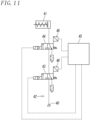
- An air control circuit equipped with a safety feature for safely controlling an air device such as an air cylinder is known as illustrated in, for example, Fig. 11 .
- a known air control circuit includes two 3-port internal-pilot-operated spring-return electromagnetic valves 43 and 44 connected in series in an air line 42 connecting an air source 40 and an air cylinder 41 to each other.
- the air control circuit can surely exhaust residual air in the air cylinder 41, despite when either the electromagnetic valve 43 or 44 suffers a breakdown and fails to operate normally during the operation of the air cylinder 41, by turning off the other electromagnetic valve 44 or 43.
- the above known air control circuit detects that the electromagnetic valve 43 or 44 suffers a breakdown with an electric signal, and has to perform control such as turning off the other electromagnetic valve with a control device 45 such as a sequencer in response to this electric signal.
- the air control circuit needs to use an electromagnetic valve equipped with limit switches 46 that detect operation positions of the electromagnetic valves 43 and 44 and outputs electric signals, and concurrently needs the sequencer and a control program for it.
- the air control circuit thus bears the cost of equipment, and has to ensure a technical expert having thorough knowledge of a safety function and a sequencer program.
- a technical problem of the present invention is to form an air control circuit including a safety function for safely controlling an air device simply with an air circuit without using, for example, an electromagnetic valve including a limit switch or a sequencer.
- an air control circuit includes a main air line in which two external-pilot-operated electromagnetic valves are connected in series, a pilot air line that supplies pilot air to the two electromagnetic valves, and a pilot control line that switches the pilot air line between a supply state to supply the pilot air to the two electromagnetic valves and an exhaust state to exhaust the pilot air from the two electromagnetic valves.
- the two electromagnetic valves in the main air line are two-position valves that have a first position for when turned off and a second position for when turned on.
- the two electromagnetic valves are connected so that, when both of the two electromagnetic valves are in the first position, the electromagnetic valves shut an air source and an air device from each other and exhaust air in the air device through one of the electromagnetic valves, when both of the two electromagnetic valves are in the second position, the electromagnetic valves connect the air source and the air device to each other to supply air from the air source to the air device, and when one of the two electromagnetic valves is in the first position and the other one of the two electromagnetic valves is in the second position, the electromagnetic valves shut the air source and the air device from each other and exhaust air in the air device through the electromagnetic valve in the first position.
- An air operation valve having a first position where the pilot air line is in the supply state and a second position where the pilot air line is in the exhaust state is connected to the pilot air line.
- the pilot control line is connected to the air source or disconnected from the air source by the two electromagnetic valves.
- the pilot control line is disconnected from the air source to hold the air operation valve in the first position where the pilot air line is in the supply state.
- the pilot control line is connected to the air source through the two electromagnetic valves to switch the air operation valve to the second position where the pilot air line is in the exhaust state with control air supplied from the air source.
- the air operation valve desirably includes a detent mechanism that holds the air operation valve in the second position, and a release button that releases holding of the detent mechanism.
- a pilot-operated check valve, a manual relief valve, and the air operation valve may be connected to the pilot control line.
- the pilot-operated check valve When pilot air from the pilot air line operates on the pilot-operated check valve, the pilot-operated check valve may allow a forward flow of the control air flowing through the pilot control line from the air source toward the air operation valve and a reverse flow opposite to the forward flow.
- the pilot-operated check valve When the pilot air does not operate on the pilot-operated check valve, the pilot-operated check valve may block the reverse flow of the control air, and the manual relief valve may switch, with a manual operation, the pilot control line from a conduction state to allow the control air to flow to an open state to exhaust the control air to an outside.
- an air tank may be connected to the pilot control line, and the air tank may store control air supplied from the air source and supply the control air to the air operation valve.
- the two electromagnetic valves may be 5-port valves, and may include one input port, a first output port, a second output port, a first exhaust port, and a second exhaust port.
- the two electromagnetic valves may include a first electromagnetic valve connected to the main air line at a portion closer to the air source and a second electromagnetic valve connected to the main air line at a portion closer to the air device.
- the input port in the first electromagnetic valve may be connected to the air source
- the first output port in the first electromagnetic valve may be connected to the input port in the second electromagnetic valve
- the second output port in the first electromagnetic valve may be connected to the second exhaust port in the second electromagnetic valve
- the first exhaust port and the second exhaust port in the first electromagnetic valve may be open to the outside
- the first output port in the second electromagnetic valve may be connected to the air device
- the second output port in the second electromagnetic valve may be connected to the pilot control line
- the first exhaust port in the second electromagnetic valve may be open to the outside.
- a delay mechanism that delays a start of the air device may be connected to the main air line.
- the delay mechanism desirably includes a switch valve operated by air, and a throttle valve that restricts the flow rate of air.
- a switch valve operated by air When both of the two electromagnetic valves are turned on to connect the air source and the air device to each other, air is desirably allowed to flow to the main air line at a restricted rate through the throttle valve.
- the switch valve When part of air output from the main air line to the air device is fed back to the switch valve, the switch valve is desirably switched to allow air from the air source to flow through the main air line in a free flowing state.
- an air control circuit including a safety function is simply formed from an air circuit without using, for example, an electromagnetic valve including a limit switch or a sequencer.
- This structure is very simple and bears a low cost of equipment, and thus does not need to ensure a technical expert having thorough knowledge of a safety function and a sequencer program.
- Fig. 1 to Fig. 5 illustrate an air control circuit including a safety function according to a first embodiment of the present invention.
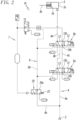
- This air control circuit 1A connects an air source 2 and an air device 3 to each other, and controls the air device 3 by supplying air from the air source 2 to the air device 3, and exhausting air in the air device 3 to the outside, and includes a main air line 4 in which two external-pilot-operated electromagnetic valves 5a and 5b are connected in series, a pilot air line 6 that supplies pilot air to the two electromagnetic valves 5a and 5b, and a pilot control line 7 that switches the pilot air line 6 between a supply state to supply pilot air to the two electromagnetic valves 5a and 5b and an exhaust state to exhaust pilot air from the two electromagnetic valves 5a and 5b.
- the air device 3 is an air cylinder
- the air cylinder 3 is a single-acting air cylinder where a piston 3a and a rod 3b are reciprocated by air supplied into a pressure chamber 3c and a return spring 3d.
- the two electromagnetic valves 5a and 5b have the same structure.
- the electromagnetic valves 5a and 5b are each switched between a first position 12 for when turned off and a second position 13 for when turned on by a return spring 11 and pilot air supplied and exhausted through the on/off operation of a single solenoid 10.
- the electromagnetic valves 5a and 5b can be said to be single-solenoid-operated spring-return two-position valves.
- the electromagnetic valves 5a and 5b are 5-port valves, and each include a single input port 14, two output ports, that is, a first output port 15a and a second output port 15b, and two exhaust ports, that is, a first exhaust port 16a and a second exhaust port 16b.
- the electromagnetic valve 5a is a first electromagnetic valve 5a connected to the main air line 4 at a portion closer to the air source 2
- the other electromagnetic valve 5b is a second electromagnetic valve 5b connected to the main air line 4 at a portion closer to the air cylinder 3.
- the input port 14 in the first electromagnetic valve 5a is connected to the air source 2 through an input line 4a
- the first output port 15a in the first electromagnetic valve 5a is connected to the input port 14 in the second electromagnetic valve 5b through a first relay line 4b
- the second output port 15b in the first electromagnetic valve 5a is connected to the second exhaust port 16b in the second electromagnetic valve 5b through a second relay line 4c
- the first exhaust port 16a and the second exhaust port 16b in the first electromagnetic valve 5a are open to the outside through silencers 17.
- the first output port 15a in the second electromagnetic valve 5b is connected to the pressure chamber 3c in the air cylinder 3 through an output line 4d, the second output port 15b in the second electromagnetic valve 5b is connected to a first end of the pilot control line 7, and the first exhaust port 16a in the second electromagnetic valve 5b is open to the outside through a silencer 17.
- the two electromagnetic valves 5a and 5b connected to the main air line 4 control the air device by being always concurrently turned on or off by a control device not illustrated, and operate in the following manner.
- the air source 2 and the air cylinder 3 are shut from each other, and air in the pressure chamber 3c in the air cylinder 3 is exhausted to the outside through the electromagnetic valve 5b.
- the input line 4a extending from the air source 2 is connected to the second relay line 4c via the first electromagnetic valve 5a, but the second relay line 4c is shut from the second electromagnetic valve 5b.
- the output line 4d that connects the air cylinder 3 and the first output port 15a in the second electromagnetic valve 5b is open to the outside through the first exhaust port 16a in the second electromagnetic valve 5b to exhaust air from the air cylinder 3.
- the piston 3a and the rod 3b in the air cylinder 3 are retracted to the initial positions by the return spring 3d.
- the pilot control line 7 is open to the outside from the input port 14 and the second output port 15b in the second electromagnetic valve 5b through the first relay line 4b, and the first output port 15a and the first exhaust port 16a in the first electromagnetic valve 5a.
- the air source 2 and the air cylinder 3 are connected to each other.
- the input line 4a extending from the air source 2, the first relay line 4b, and the output line 4d are sequentially connected to each other through the first electromagnetic valve 5a and the second electromagnetic valve 5b, and air is supplied from the air source 2 to the pressure chamber 3c in the air cylinder 3.
- the piston 3a and the rod 3b in the air cylinder 3 move forward toward the operation position.
- the pilot control line 7 is open to the outside from the second output port 15b and the second exhaust port 16b in the second electromagnetic valve 5b through the second relay line 4c, and the second output port 15b and the second exhaust port 16b in the first electromagnetic valve 5a.
- the input line 4a extending from the air source 2 is connected to the pilot control line 7 from the first electromagnetic valve 5a through the first relay line 4b and the second electromagnetic valve 5b to supply control air to the pilot control line 7.
- the output line 4d connected to the air cylinder 3 is shut from the air source 2 and is open to the outside through the first output port 15a and the first exhaust port 16a in the second electromagnetic valve 5b.
- air in the air cylinder 3 is exhausted through the second electromagnetic valve 5b, and the air cylinder 3 is returned to the initial position.
- the input line 4a extending from the air source 2 is connected to the pilot control line 7 from the first electromagnetic valve 5a through the second relay line 4c and the second electromagnetic valve 5b, and thus, control air is supplied to the pilot control line 7.
- the output line 4d is shut from the air source 2, and is open to the outside from the second electromagnetic valve 5b through the first relay line 4b, and the first output port 15a and the first exhaust port 16a in the first electromagnetic valve 5a.
- air in the air cylinder 3 is exhausted through the first electromagnetic valve 5a, and the air cylinder 3 is returned to the initial position.
- the pilot air line 6 diverges from the main air line 4 at a portion between the air source 2 and the first electromagnetic valve 5a, and is connected to pilot ports 21 in the first electromagnetic valve 5a and the second electromagnetic valve 5b through an air operation valve 20 connected to the pilot air line 6.
- an input side (a side connected to the air source 2) of the air operation valve 20 is referred to as a primary side
- an output side (a side connected to the electromagnetic valves 5a and 5b) of the air operation valve 20 is referred to as a secondary side.
- a portion from the air source 2 to the air operation valve 20 serves as a primary side line 6a
- a portion from the air operation valve 20 to the two electromagnetic valves 5a and 5b serves as a secondary side line 6b.
- the air operation valve 20 is a 3-port valve switchable between two positions with operations of a return spring 22 and control air supplied through the pilot control line 7. As illustrated in Fig. 1 and Fig. 2 , when the pilot control line 7 is disconnected from the air source 2 and the control air does not operate, the air operation valve 20 is switched by the return spring 22 to a first position 20a to hold the pilot air line 6 in a supply state where the primary side line 6a and the secondary side line 6b are connected to each other. As illustrated in Fig. 3 and Fig.
- the air operation valve 20 is switched by the control air to a second position 20b to shut the secondary side line 6b and the primary side line 6a in the pilot air line 6 from each other, and the secondary side line 6b becomes open to the outside to be in an exhaust state.
- a pilot-operated check valve 23, a manual relief valve 24, and an air tank 25 are sequentially connected in series to the pilot control line 7, from the second electromagnetic valve 5b toward the air operation valve 20, and a pilot lamp 26 that indicates that control air is being supplied to the pilot control line 7 is connected to a display line 7a that diverges from a portion between the manual relief valve 24 and the air tank 25.
- the pilot-operated check valve 23 When pilot air from the pilot air line 6 operates, the pilot-operated check valve 23 allows the pilot control line 7 to conduct in both directions, and when the pilot air does not operate, the pilot-operated check valve 23 allows the pilot control line 7 to conduct simply in one direction. In other words, when the pilot air operates, the pilot-operated check valve 23 allows a forward flow of control air flowing through the pilot control line 7 from the air source 2 toward the air operation valve 20 and a reverse flow of control air flowing from the air operation valve 20 toward the air source 2. When the pilot air does not operate, the pilot-operated check valve 23 simply allows the forward flow of the control air, and blocks the reverse flow.
- the manual relief valve 24 is a 3-port valve switchable between two positions by an operation lever 27 and a return spring 28. As illustrated in Fig. 1 , when the manual relief valve 24 is switched to a first position 24a by the return spring 28, the manual relief valve 24 holds the pilot control line 7 in a conduction state to allow the control air to flow. When the manual relief valve 24 is switched to a second position 24b in Fig. 5 by the operation lever 27, the manual relief valve 24 holds the pilot control line 7 in an open state to exhaust the control air to the outside. When the operation lever 27 is released, the manual relief valve 24 is returned to the first position 24a by the return spring 28.
- the air tank 25 After storing the control air supplied from the air source 2 therein, the air tank 25 supplies the control air to the air operation valve 20 therefrom to stabilize supply of the control air.
- Fig. 1 illustrates a state where the first electromagnetic valve 5a and the second electromagnetic valve 5b are both turned off and located in the first position 12, and the main air line 4 shuts the air source 2 and the air cylinder 3 from each other.
- the air control circuit 1A is returned to the operation state illustrated in Fig. 1 .
- the air cylinder 3 is also returned to the initial position.
- the pilot control line 7 is connected to the air source 2 through the first electromagnetic valve 5a and the second electromagnetic valve 5b, and thus control air is supplied from the air source 2 to the pilot control line 7.
- the control air is stored in the air tank 25 through the pilot-operated check valve 23 and the manual relief valve 24, and then supplied from the air tank 25 to the air operation valve 20 to switch the air operation valve 20 to the second position 20b.
- the primary side line 6a and the secondary side line 6b in the pilot air line 6 are shut from each other, and the secondary side line 6b becomes open to the outside to become an exhaust state.
- pilot air in the first electromagnetic valve 5a and the second electromagnetic valve 5b are exhausted, and thus the first electromagnetic valve 5a and the second electromagnetic valve 5b are disabled from restarting.
- the pilot air in the secondary side line 6b When the pilot air in the secondary side line 6b is exhausted, the pilot air no longer operates on the pilot-operated check valve 23.
- the pilot-operated check valve 23 exerts its original non-return function to prevent the control air from reversely flowing through the pilot control line 7 from the air operation valve 20 toward the air source 2.
- the pilot lamp 26 When the control air is supplied to the pilot control line 7, the pilot lamp 26 is lighted to notify an operator that any of the electromagnetic valves 5a and 5b suffers a breakdown.
- the pilot control line 7 is connected to the air source 2 through the second electromagnetic valve 5b and the first electromagnetic valve 5a, and the control air is supplied to the pilot control line 7.
- the air operation valve 20 exhausts the pilot air in the first electromagnetic valve 5a and the second electromagnetic valve 5b to prevent the first electromagnetic valve 5a and the second electromagnetic valve 5b from restarting.
- the pilot-operated check valve 23 and the pilot lamp 26 also operate in the same manner as in the case described above.
- Such an operation of the air control circuit 1A prevents a risk such as a restart of the electromagnetic valve 5a or 5b during inspection of the breakdown or a sudden start of the air cylinder 3.
- the operation lever 27 in the manual relief valve 24 is manually operated to switch the manual relief valve 24 to the second position 24b.
- the pilot control line 7 is in the open state and the control air in the air tank 25 is exhausted to the outside.
- the air operation valve 20 is switched to the first position 20a by the return spring 22 to make the pilot air line 6 to the supply state.
- the pilot air from the air source 2 is supplied to the first electromagnetic valve 5a and the second electromagnetic valve 5b, and the first electromagnetic valve 5a and the second electromagnetic valve 5b become the restartable state.
- the pilot-operated check valve 23 allows the pilot control line 7 to conduct in both of the forward direction and the reverse direction with the operation of the pilot air.
- the air tank 25 is connected to the pilot control line 7, but this air tank 25 is not necessarily provided.
- Fig. 6 illustrates an example of connection when the manual relief valve 24 formed from a 2-port valve is used.
- the manual relief valve 24 is connected to a relief line 7b that diverges from the pilot control line 7.
- the manual relief valve 24 is normally positioned at the first position 24a and shuts the relief line 7b. However, when the operation lever 27 is operated, the manual relief valve 24 is switched to the second position 24b to release the relief line 7b to the outside through a silencer 18. Thus, the control air in the pilot control line 7 is exhausted to the outside.
- FIG. 7 illustrates an air control circuit according to a second embodiment of the present invention.
- An air control circuit 1B according to the second embodiment differs from the air control circuit 1A according to the first embodiment in that an air operation valve 20 connected to the pilot air line 6 includes a detent mechanism 50 that holds the air operation valve 20 in the second position 20b, and a release button 51 that releases holding of the detent mechanism 50.
- the detent mechanism 50 includes a variable member 50a that changes its position integrally with the air operation valve 20, and a locking member 50b in which the variable member 50a can be locked.
- the air operation valve 20 is switched to the second position 20b by the control air from the pilot control line 7, the variable member 50a is locked in the locking member 50b, and thus the air operation valve 20 is held in the second position 20b.
- the release button 51 When the release button 51 is pushed, the release button 51 releases the locking of the locking member 5b in the variable member 50a, and makes the air operation valve 20 displaceable toward the first position 20a with an urging force of the return spring 22.
- the reason why the detent mechanism 50 is provided is to prevent, in the case where, under the state where one of the electromagnetic valves 5a and 5b suffers a breakdown and fails to be normally switched, the air operation valve 20 is switched to the second position 20b with the operation of the control air supplied from the pilot control line 7, and then the control air fails to operate on the air operation valve 20 because of, for example, insufficient air held in the tank 25, the electromagnetic valves 5a or 5b from becoming a restartable state by returning the air operation valve 20 to the first position 20a with the return spring 22, and changing the pilot air line 6 to a supply state to supply pilot air to the electromagnetic valve 5a or 5b.
- the components and the operation of the air control circuit 1B other than the air operation valve 20 are the same as the components and the operation of the air control circuit 1A according to the first embodiment.
- the same main components in both embodiments are denoted with the same reference signs without being described.
- the release button 51 may be configured to operate while being linked with a push-down operation of the operation lever 27 in the manual relief valve 24.
- FIG. 8 illustrates an air control circuit according to a third embodiment of the present invention.
- An air control circuit 1C according to this third embodiment differs from the air control circuit 1A according to the first embodiment in that a delay mechanism 30 to delay the start of the air cylinder 3 is connected to the main air line 4.
- the delay mechanism 30 includes a switch valve 31 that is switchable between two positions with air and a return spring 32, and a throttle valve 33 that restricts the flow rate of air, and that is connected between the air source 2 and the first electromagnetic valve 5a.
- the switch valve 31 is a 3-port valve, and includes a first port 34 connected to the input line 4a in the main air line 4, a second port 35 connected to a divergence line 4e that diverges from the input line 4a, and a third port 36 connected to the input port 14 in the first electromagnetic valve 5a with a third relay line 4f.
- the switch valve 31 is switched between a first position 31a in Fig. 8 and a second position 31b in Fig. 9 by the return spring 32 and feedback air that is fed back from the output line 4d connecting the second electromagnetic valve 5b and the air cylinder 3 through a feedback line 37.
- the throttle valve 33 is a variable throttle valve that can adjust the cross section of the flow path.
- the air control circuit 1C when the switch valve 31 is in the first position 31a as illustrated in Fig. 8 , the first electromagnetic valve 5a and the second electromagnetic valve 5b are both turned on to be switched to the second position 13 (refer to the main air line 4 in Fig. 2 ), and the air source 2 and the air cylinder 3 are connected through the throttle valve 33, air from the air source 2 is supplied to the air cylinder 3 while having its flow rate restricted through the throttle valve 33. Thus, the air cylinder 3 starts slowly.
- the components and the operation of the air control circuit 1C other than the delay mechanism 30 are the same as the components and the operation of the air control circuit 1A according to the first embodiment. Thus, the same main components between both embodiments are denoted with the same reference signs without being described.
- the switch valve 33 in the delay mechanism 30 is a 3-port valve, a 2-port valve may be used instead.
- the switch valve 31 and the throttle valve 33 are connected in parallel between the input line 4a and the third relay line 4f.
- the switch valve 31 is located in the first position 31a to shut the flow path. Air from the input line 4a thus flows in the third relay line 4f while having its flow rate restricted by the throttle valve 33.
- the switch valve 31 is switched to the second position 31b.
- air from the input line 4a flows to the third relay line 4f at a free flowing state through the switch valve 31.
- the air operation valve 20 may include the detent mechanism 50 and the release button 51 as in the case of the air operation valve 20 in the air control circuit 1B according to the second embodiment.
- the air device 3 may be other than an air cylinder, for example, another pilot electromagnetic valve that controls the air device such as an air cylinder.
- another pilot electromagnetic valve that controls the air device such as an air cylinder.
- the air device 3 can perform control to exhaust the pilot air in the pilot electromagnetic valve and reset the air device in case of emergency.
- each of the air control circuits 1A, 1B, and 1C is simply formed from an air circuit.
- the air control circuit is advantageous in that it has a very simple structure, it bears a low cost of equipment, and it has no need to ensure a technical expert having thorough knowledge of a safety function and a sequencer program.
Landscapes
- Engineering & Computer Science (AREA)
- Physics & Mathematics (AREA)
- Fluid Mechanics (AREA)
- Mechanical Engineering (AREA)
- General Engineering & Computer Science (AREA)
- Chemical & Material Sciences (AREA)
- Analytical Chemistry (AREA)
- General Physics & Mathematics (AREA)
- Automation & Control Theory (AREA)
- Fluid-Pressure Circuits (AREA)
- Safety Devices In Control Systems (AREA)
Abstract
Description
- The present invention relates to an air control circuit equipped with a safety feature for safely controlling an air device such as an air cylinder.
- An air control circuit equipped with a safety feature for safely controlling an air device such as an air cylinder is known as illustrated in, for example,
Fig. 11 . A known air control circuit includes two 3-port internal-pilot-operated spring-return electromagnetic valves 43 and 44 connected in series in an air line 42 connecting an air source 40 and an air cylinder 41 to each other. The air control circuit can surely exhaust residual air in the air cylinder 41, despite when either the electromagnetic valve 43 or 44 suffers a breakdown and fails to operate normally during the operation of the air cylinder 41, by turning off the other electromagnetic valve 44 or 43. - The above known air control circuit detects that the electromagnetic valve 43 or 44 suffers a breakdown with an electric signal, and has to perform control such as turning off the other electromagnetic valve with a control device 45 such as a sequencer in response to this electric signal. Thus, the air control circuit needs to use an electromagnetic valve equipped with limit switches 46 that detect operation positions of the electromagnetic valves 43 and 44 and outputs electric signals, and concurrently needs the sequencer and a control program for it. The air control circuit thus bears the cost of equipment, and has to ensure a technical expert having thorough knowledge of a safety function and a sequencer program.
- A technical problem of the present invention is to form an air control circuit including a safety function for safely controlling an air device simply with an air circuit without using, for example, an electromagnetic valve including a limit switch or a sequencer.
- To solve the above problem, an air control circuit according to the present invention includes a main air line in which two external-pilot-operated electromagnetic valves are connected in series, a pilot air line that supplies pilot air to the two electromagnetic valves, and a pilot control line that switches the pilot air line between a supply state to supply the pilot air to the two electromagnetic valves and an exhaust state to exhaust the pilot air from the two electromagnetic valves.
- The two electromagnetic valves in the main air line are two-position valves that have a first position for when turned off and a second position for when turned on. The two electromagnetic valves are connected so that, when both of the two electromagnetic valves are in the first position, the electromagnetic valves shut an air source and an air device from each other and exhaust air in the air device through one of the electromagnetic valves, when both of the two electromagnetic valves are in the second position, the electromagnetic valves connect the air source and the air device to each other to supply air from the air source to the air device, and when one of the two electromagnetic valves is in the first position and the other one of the two electromagnetic valves is in the second position, the electromagnetic valves shut the air source and the air device from each other and exhaust air in the air device through the electromagnetic valve in the first position.
- An air operation valve having a first position where the pilot air line is in the supply state and a second position where the pilot air line is in the exhaust state is connected to the pilot air line.
- In addition, the pilot control line is connected to the air source or disconnected from the air source by the two electromagnetic valves. When both of the two electromagnetic valves are in the first position and when both of the two electromagnetic valves are in the second position, the pilot control line is disconnected from the air source to hold the air operation valve in the first position where the pilot air line is in the supply state. When one of the two electromagnetic valves is in the first position and the other one of the two electromagnetic valves is in the second position, the pilot control line is connected to the air source through the two electromagnetic valves to switch the air operation valve to the second position where the pilot air line is in the exhaust state with control air supplied from the air source.
- In the present invention, the air operation valve desirably includes a detent mechanism that holds the air operation valve in the second position, and a release button that releases holding of the detent mechanism.
- In the air control circuit according to the present invention, a pilot-operated check valve, a manual relief valve, and the air operation valve may be connected to the pilot control line. When pilot air from the pilot air line operates on the pilot-operated check valve, the pilot-operated check valve may allow a forward flow of the control air flowing through the pilot control line from the air source toward the air operation valve and a reverse flow opposite to the forward flow. When the pilot air does not operate on the pilot-operated check valve, the pilot-operated check valve may block the reverse flow of the control air, and the manual relief valve may switch, with a manual operation, the pilot control line from a conduction state to allow the control air to flow to an open state to exhaust the control air to an outside.
- In the air control circuit according to the present invention, an air tank may be connected to the pilot control line, and the air tank may store control air supplied from the air source and supply the control air to the air operation valve.
- In the air control circuit according to the present invention, the two electromagnetic valves may be 5-port valves, and may include one input port, a first output port, a second output port, a first exhaust port, and a second exhaust port. The two electromagnetic valves may include a first electromagnetic valve connected to the main air line at a portion closer to the air source and a second electromagnetic valve connected to the main air line at a portion closer to the air device. The input port in the first electromagnetic valve may be connected to the air source, the first output port in the first electromagnetic valve may be connected to the input port in the second electromagnetic valve, the second output port in the first electromagnetic valve may be connected to the second exhaust port in the second electromagnetic valve, the first exhaust port and the second exhaust port in the first electromagnetic valve may be open to the outside, the first output port in the second electromagnetic valve may be connected to the air device, the second output port in the second electromagnetic valve may be connected to the pilot control line, and the first exhaust port in the second electromagnetic valve may be open to the outside.
- In the air control circuit in the present invention, a delay mechanism that delays a start of the air device may be connected to the main air line.
- In this case, the delay mechanism desirably includes a switch valve operated by air, and a throttle valve that restricts the flow rate of air. When both of the two electromagnetic valves are turned on to connect the air source and the air device to each other, air is desirably allowed to flow to the main air line at a restricted rate through the throttle valve. When part of air output from the main air line to the air device is fed back to the switch valve, the switch valve is desirably switched to allow air from the air source to flow through the main air line in a free flowing state.
- According to the present invention, an air control circuit including a safety function is simply formed from an air circuit without using, for example, an electromagnetic valve including a limit switch or a sequencer. This structure is very simple and bears a low cost of equipment, and thus does not need to ensure a technical expert having thorough knowledge of a safety function and a sequencer program.
-
- [
Fig. 1] Fig. 1 is a circuit diagram of an air control circuit according to a first embodiment of the present invention. - [
Fig. 2] Fig. 2 is a circuit diagram illustrating a different operation state of the air control circuit. - [
Fig. 3] Fig. 3 is a circuit diagram illustrating another different operation state of the air control circuit. - [
Fig. 4] Fig. 4 is a circuit diagram illustrating another different operation state of the air control circuit. - [
Fig. 5] Fig. 5 is a diagram of a manual relief valve when operated. - [
Fig. 6] Fig. 6 is a connection diagram of a different example of a manual relief valve. - [
Fig. 7] Fig. 7 is a circuit diagram of an air control circuit according to a second embodiment of the present invention. - [
Fig. 8] Fig. 8 is a circuit diagram of an air control circuit according to a third embodiment of the present invention. - [
Fig. 9] Fig. 9 is a diagram of a different operation state of a delay mechanism inFig. 8 . - [
Fig. 10] Fig. 10 is a connection diagram of a different example of a delay mechanism. - [
Fig. 11] Fig. 11 is a circuit diagram of a known air control circuit. Description of Embodiments -
Fig. 1 to Fig. 5 illustrate an air control circuit including a safety function according to a first embodiment of the present invention. Thisair control circuit 1A connects anair source 2 and anair device 3 to each other, and controls theair device 3 by supplying air from theair source 2 to theair device 3, and exhausting air in theair device 3 to the outside, and includes amain air line 4 in which two external-pilot-operatedelectromagnetic valves pilot air line 6 that supplies pilot air to the twoelectromagnetic valves pilot control line 7 that switches thepilot air line 6 between a supply state to supply pilot air to the twoelectromagnetic valves electromagnetic valves - In the present embodiment, the
air device 3 is an air cylinder, and theair cylinder 3 is a single-acting air cylinder where apiston 3a and arod 3b are reciprocated by air supplied into apressure chamber 3c and areturn spring 3d. - The two
electromagnetic valves electromagnetic valves first position 12 for when turned off and asecond position 13 for when turned on by areturn spring 11 and pilot air supplied and exhausted through the on/off operation of asingle solenoid 10. Thus, theelectromagnetic valves - The
electromagnetic valves single input port 14, two output ports, that is, afirst output port 15a and asecond output port 15b, and two exhaust ports, that is, afirst exhaust port 16a and asecond exhaust port 16b. - Of the two
electromagnetic valves electromagnetic valve 5a is a firstelectromagnetic valve 5a connected to themain air line 4 at a portion closer to theair source 2, and the otherelectromagnetic valve 5b is a secondelectromagnetic valve 5b connected to themain air line 4 at a portion closer to theair cylinder 3. Theinput port 14 in the firstelectromagnetic valve 5a is connected to theair source 2 through aninput line 4a, thefirst output port 15a in the firstelectromagnetic valve 5a is connected to theinput port 14 in the secondelectromagnetic valve 5b through afirst relay line 4b, thesecond output port 15b in the firstelectromagnetic valve 5a is connected to thesecond exhaust port 16b in the secondelectromagnetic valve 5b through asecond relay line 4c, and thefirst exhaust port 16a and thesecond exhaust port 16b in the firstelectromagnetic valve 5a are open to the outside throughsilencers 17. Thefirst output port 15a in the secondelectromagnetic valve 5b is connected to thepressure chamber 3c in theair cylinder 3 through anoutput line 4d, thesecond output port 15b in the secondelectromagnetic valve 5b is connected to a first end of thepilot control line 7, and thefirst exhaust port 16a in the secondelectromagnetic valve 5b is open to the outside through asilencer 17. - The two
electromagnetic valves main air line 4 control the air device by being always concurrently turned on or off by a control device not illustrated, and operate in the following manner. - Firstly, as illustrated in
Fig. 1 , when the twoelectromagnetic valves first position 12, theair source 2 and theair cylinder 3 are shut from each other, and air in thepressure chamber 3c in theair cylinder 3 is exhausted to the outside through theelectromagnetic valve 5b. Specifically, theinput line 4a extending from theair source 2 is connected to thesecond relay line 4c via the firstelectromagnetic valve 5a, but thesecond relay line 4c is shut from the secondelectromagnetic valve 5b. In addition, theoutput line 4d that connects theair cylinder 3 and thefirst output port 15a in the secondelectromagnetic valve 5b is open to the outside through thefirst exhaust port 16a in the secondelectromagnetic valve 5b to exhaust air from theair cylinder 3. Thus, thepiston 3a and therod 3b in theair cylinder 3 are retracted to the initial positions by thereturn spring 3d. - At this time, the
pilot control line 7 is open to the outside from theinput port 14 and thesecond output port 15b in the secondelectromagnetic valve 5b through thefirst relay line 4b, and thefirst output port 15a and thefirst exhaust port 16a in the firstelectromagnetic valve 5a. - As illustrated in
Fig. 2 , when the twoelectromagnetic valves second position 13, theair source 2 and theair cylinder 3 are connected to each other. Specifically, theinput line 4a extending from theair source 2, thefirst relay line 4b, and theoutput line 4d are sequentially connected to each other through the firstelectromagnetic valve 5a and the secondelectromagnetic valve 5b, and air is supplied from theair source 2 to thepressure chamber 3c in theair cylinder 3. Thus, thepiston 3a and therod 3b in theair cylinder 3 move forward toward the operation position. - At this time, the
pilot control line 7 is open to the outside from thesecond output port 15b and thesecond exhaust port 16b in the secondelectromagnetic valve 5b through thesecond relay line 4c, and thesecond output port 15b and thesecond exhaust port 16b in the firstelectromagnetic valve 5a. - Subsequently, when the two
electromagnetic valves air control circuit 1A and theair cylinder 3 to the state inFig. 1 , and when one of the electromagnetic valves suffers a breakdown and fails to be switched to thefirst position 12, as will be described below, theair source 2 and theair device 3 are shut from each other and air in thepressure chamber 3c in theair cylinder 3 is exhausted through theelectromagnetic valve first position 12. - First, as illustrated in
Fig. 3 , when the firstelectromagnetic valve 5a suffers a breakdown to be left in thesecond position 13 and the secondelectromagnetic valve 5b operates normally to return to thefirst position 12, theinput line 4a extending from theair source 2 is connected to thepilot control line 7 from the firstelectromagnetic valve 5a through thefirst relay line 4b and the secondelectromagnetic valve 5b to supply control air to thepilot control line 7. In contrast, theoutput line 4d connected to theair cylinder 3 is shut from theair source 2 and is open to the outside through thefirst output port 15a and thefirst exhaust port 16a in the secondelectromagnetic valve 5b. Thus, air in theair cylinder 3 is exhausted through the secondelectromagnetic valve 5b, and theair cylinder 3 is returned to the initial position. - As illustrated in
Fig. 4 , when the firstelectromagnetic valve 5a operates normally to return to thefirst position 12 and the secondelectromagnetic valve 5b suffers a breakdown to be left in thesecond position 13, theinput line 4a extending from theair source 2 is connected to thepilot control line 7 from the firstelectromagnetic valve 5a through thesecond relay line 4c and the secondelectromagnetic valve 5b, and thus, control air is supplied to thepilot control line 7. In contrast, theoutput line 4d is shut from theair source 2, and is open to the outside from the secondelectromagnetic valve 5b through thefirst relay line 4b, and thefirst output port 15a and thefirst exhaust port 16a in the firstelectromagnetic valve 5a. Thus, air in theair cylinder 3 is exhausted through the firstelectromagnetic valve 5a, and theair cylinder 3 is returned to the initial position. - Referring back to
Fig. 1 , thepilot air line 6 diverges from themain air line 4 at a portion between theair source 2 and the firstelectromagnetic valve 5a, and is connected to pilotports 21 in the firstelectromagnetic valve 5a and the secondelectromagnetic valve 5b through anair operation valve 20 connected to thepilot air line 6. - In the following description, an input side (a side connected to the air source 2) of the
air operation valve 20 is referred to as a primary side, and an output side (a side connected to theelectromagnetic valves air operation valve 20 is referred to as a secondary side. Thus, of thepilot air line 6, a portion from theair source 2 to theair operation valve 20 serves as aprimary side line 6a, and a portion from theair operation valve 20 to the twoelectromagnetic valves secondary side line 6b. - The
air operation valve 20 is a 3-port valve switchable between two positions with operations of areturn spring 22 and control air supplied through thepilot control line 7. As illustrated inFig. 1 andFig. 2 , when thepilot control line 7 is disconnected from theair source 2 and the control air does not operate, theair operation valve 20 is switched by thereturn spring 22 to afirst position 20a to hold thepilot air line 6 in a supply state where theprimary side line 6a and thesecondary side line 6b are connected to each other. As illustrated inFig. 3 andFig. 4 , when thepilot control line 7 is connected to theair source 2 and the control air operates, theair operation valve 20 is switched by the control air to asecond position 20b to shut thesecondary side line 6b and theprimary side line 6a in thepilot air line 6 from each other, and thesecondary side line 6b becomes open to the outside to be in an exhaust state. - A pilot-operated
check valve 23, amanual relief valve 24, and anair tank 25 are sequentially connected in series to thepilot control line 7, from the secondelectromagnetic valve 5b toward theair operation valve 20, and apilot lamp 26 that indicates that control air is being supplied to thepilot control line 7 is connected to adisplay line 7a that diverges from a portion between themanual relief valve 24 and theair tank 25. - When pilot air from the
pilot air line 6 operates, the pilot-operatedcheck valve 23 allows thepilot control line 7 to conduct in both directions, and when the pilot air does not operate, the pilot-operatedcheck valve 23 allows thepilot control line 7 to conduct simply in one direction. In other words, when the pilot air operates, the pilot-operatedcheck valve 23 allows a forward flow of control air flowing through thepilot control line 7 from theair source 2 toward theair operation valve 20 and a reverse flow of control air flowing from theair operation valve 20 toward theair source 2. When the pilot air does not operate, the pilot-operatedcheck valve 23 simply allows the forward flow of the control air, and blocks the reverse flow. - The
manual relief valve 24 is a 3-port valve switchable between two positions by anoperation lever 27 and areturn spring 28. As illustrated inFig. 1 , when themanual relief valve 24 is switched to afirst position 24a by thereturn spring 28, themanual relief valve 24 holds thepilot control line 7 in a conduction state to allow the control air to flow. When themanual relief valve 24 is switched to asecond position 24b inFig. 5 by theoperation lever 27, themanual relief valve 24 holds thepilot control line 7 in an open state to exhaust the control air to the outside. When theoperation lever 27 is released, themanual relief valve 24 is returned to thefirst position 24a by thereturn spring 28. - After storing the control air supplied from the
air source 2 therein, theair tank 25 supplies the control air to theair operation valve 20 therefrom to stabilize supply of the control air. - Subsequently, the operation of the entirety of the
air control circuit 1A is described. -
Fig. 1 illustrates a state where the firstelectromagnetic valve 5a and the secondelectromagnetic valve 5b are both turned off and located in thefirst position 12, and themain air line 4 shuts theair source 2 and theair cylinder 3 from each other. - At this time, air in the
pressure chamber 3c in theair cylinder 3 is exhausted to the outside from theoutput line 4d through the secondelectromagnetic valve 5b, and thus theair cylinder 3 is in the initial position where therod 3b is retracted. The control air from theair source 2 is not supplied to thepilot control line 7, and thus theair operation valve 20 is located in thefirst position 20a to hold thepilot air line 6 in the supply state. Thus, the pilot air from theair source 2 is supplied to the firstelectromagnetic valve 5a and the secondelectromagnetic valve 5b through thepilot air line 6. In addition, the pilot-operatedcheck valve 23 allows thepilot control line 7 to conduct in both directions with the operation of the pilot air. - From this state, as illustrated in
Fig. 2 , when the firstelectromagnetic valve 5a and the secondelectromagnetic valve 5b are concurrently turned on to be switched to thesecond position 13, theair source 2 and thepressure chamber 3c in theair cylinder 3 are connected to each other through theinput line 4a, the firstelectromagnetic valve 5a, thefirst relay line 4b, the secondelectromagnetic valve 5b, and theoutput line 4d. Thus, air is supplied from theair source 2 to thepressure chamber 3c, and therod 3b in theair cylinder 3 is thus moved forward toward the operation position. - At this time, the
pilot control line 7 is shut from theair source 2. - When an operation process performed by the
air cylinder 3 is finished, the firstelectromagnetic valve 5a and the secondelectromagnetic valve 5b are concurrently turned off, and theair control circuit 1A is returned to the operation state illustrated inFig. 1 . Thus, theair cylinder 3 is also returned to the initial position. - However, when one of the two
electromagnetic valves first position 12, as described below, air in theair cylinder 3 is exhausted through the returnedelectromagnetic valve air cylinder 3 is returned to the initial position, and concurrently, pilot air in the firstelectromagnetic valve 5a and the secondelectromagnetic valve 5b is automatically exhausted, so that the firstelectromagnetic valve 5a and the secondelectromagnetic valve 5b are prevented from being restarted. - First, as illustrated in
Fig. 3 , when the secondelectromagnetic valve 5b is turned off to be switched to thefirst position 12, and the firstelectromagnetic valve 5a suffers a breakdown to be left in thesecond position 13, theoutput line 4d connected to theair cylinder 3 becomes open to the outside through the secondelectromagnetic valve 5b. Thus, air in theair cylinder 3 is exhausted through the secondelectromagnetic valve 5b, and theair cylinder 3 is returned to the initial position. - At this time, the
pilot control line 7 is connected to theair source 2 through the firstelectromagnetic valve 5a and the secondelectromagnetic valve 5b, and thus control air is supplied from theair source 2 to thepilot control line 7. The control air is stored in theair tank 25 through the pilot-operatedcheck valve 23 and themanual relief valve 24, and then supplied from theair tank 25 to theair operation valve 20 to switch theair operation valve 20 to thesecond position 20b. Then, theprimary side line 6a and thesecondary side line 6b in thepilot air line 6 are shut from each other, and thesecondary side line 6b becomes open to the outside to become an exhaust state. Thus, pilot air in the firstelectromagnetic valve 5a and the secondelectromagnetic valve 5b are exhausted, and thus the firstelectromagnetic valve 5a and the secondelectromagnetic valve 5b are disabled from restarting. - When the pilot air in the
secondary side line 6b is exhausted, the pilot air no longer operates on the pilot-operatedcheck valve 23. Thus, the pilot-operatedcheck valve 23 exerts its original non-return function to prevent the control air from reversely flowing through thepilot control line 7 from theair operation valve 20 toward theair source 2. - When the control air is supplied to the
pilot control line 7, thepilot lamp 26 is lighted to notify an operator that any of theelectromagnetic valves - In contrast, as illustrated in
Fig. 4 , when the firstelectromagnetic valve 5a is turned off to be switched to thefirst position 12, and the secondelectromagnetic valve 5b suffers a breakdown to be left in thesecond position 13, theoutput line 4d connected to theair cylinder 3 becomes open to the outside from the secondelectromagnetic valve 5b through thefirst relay line 4b and the firstelectromagnetic valve 5a, and air in theair cylinder 3 is exhausted, so that theair cylinder 3 is returned to the initial position. - Also in this case, the
pilot control line 7 is connected to theair source 2 through the secondelectromagnetic valve 5b and the firstelectromagnetic valve 5a, and the control air is supplied to thepilot control line 7. Thus, as in the case inFig. 3 , theair operation valve 20 exhausts the pilot air in the firstelectromagnetic valve 5a and the secondelectromagnetic valve 5b to prevent the firstelectromagnetic valve 5a and the secondelectromagnetic valve 5b from restarting. The pilot-operatedcheck valve 23 and thepilot lamp 26 also operate in the same manner as in the case described above. - Such an operation of the
air control circuit 1A prevents a risk such as a restart of theelectromagnetic valve air cylinder 3. - From the states in
Fig. 3 andFig. 4 , to make theair control circuit 1A into a restartable state after theelectromagnetic valve Fig. 5 , theoperation lever 27 in themanual relief valve 24 is manually operated to switch themanual relief valve 24 to thesecond position 24b. Thus, thepilot control line 7 is in the open state and the control air in theair tank 25 is exhausted to the outside. Thus, theair operation valve 20 is switched to thefirst position 20a by thereturn spring 22 to make thepilot air line 6 to the supply state. Thus, the pilot air from theair source 2 is supplied to the firstelectromagnetic valve 5a and the secondelectromagnetic valve 5b, and the firstelectromagnetic valve 5a and the secondelectromagnetic valve 5b become the restartable state. In addition, the pilot-operatedcheck valve 23 allows thepilot control line 7 to conduct in both of the forward direction and the reverse direction with the operation of the pilot air. - When the operation on the
operation lever 27 is released, themanual relief valve 24 is returned to thefirst position 24a by thereturn spring 28. - In the embodiment, the
air tank 25 is connected to thepilot control line 7, but thisair tank 25 is not necessarily provided. - In addition, although the
manual relief valve 24 is a 3-port valve, a 2-port valve may be used instead.Fig. 6 illustrates an example of connection when themanual relief valve 24 formed from a 2-port valve is used. In this example, themanual relief valve 24 is connected to arelief line 7b that diverges from thepilot control line 7. - The
manual relief valve 24 is normally positioned at thefirst position 24a and shuts therelief line 7b. However, when theoperation lever 27 is operated, themanual relief valve 24 is switched to thesecond position 24b to release therelief line 7b to the outside through asilencer 18. Thus, the control air in thepilot control line 7 is exhausted to the outside. -
Fig. 7 illustrates an air control circuit according to a second embodiment of the present invention. Anair control circuit 1B according to the second embodiment differs from theair control circuit 1A according to the first embodiment in that anair operation valve 20 connected to thepilot air line 6 includes adetent mechanism 50 that holds theair operation valve 20 in thesecond position 20b, and arelease button 51 that releases holding of thedetent mechanism 50. - The
detent mechanism 50 includes avariable member 50a that changes its position integrally with theair operation valve 20, and a lockingmember 50b in which thevariable member 50a can be locked. When theair operation valve 20 is switched to thesecond position 20b by the control air from thepilot control line 7, thevariable member 50a is locked in the lockingmember 50b, and thus theair operation valve 20 is held in thesecond position 20b. - When the
release button 51 is pushed, therelease button 51 releases the locking of the lockingmember 5b in thevariable member 50a, and makes theair operation valve 20 displaceable toward thefirst position 20a with an urging force of thereturn spring 22. - The reason why the
detent mechanism 50 is provided is to prevent, in the case where, under the state where one of theelectromagnetic valves air operation valve 20 is switched to thesecond position 20b with the operation of the control air supplied from thepilot control line 7, and then the control air fails to operate on theair operation valve 20 because of, for example, insufficient air held in thetank 25, theelectromagnetic valves air operation valve 20 to thefirst position 20a with thereturn spring 22, and changing thepilot air line 6 to a supply state to supply pilot air to theelectromagnetic valve - The components and the operation of the
air control circuit 1B other than theair operation valve 20 are the same as the components and the operation of theair control circuit 1A according to the first embodiment. Thus, the same main components in both embodiments are denoted with the same reference signs without being described. - The
release button 51 may be configured to operate while being linked with a push-down operation of theoperation lever 27 in themanual relief valve 24. - In such a case, when, from the state in
Fig. 7 , theoperation lever 27 in themanual relief valve 24 is pushed to switch themanual relief valve 24 to thesecond position 24b, a release button 53 is operated while being linked with the operation, and theair operation valve 20 is switched to thefirst position 20a. Thus, thepilot control line 7 becomes the open state to exhaust the control air to the outside, and thepilot air line 6 becomes the supply state to supply the pilot air to theelectromagnetic valve - When the pressure on the
operation lever 27 is released, themanual relief valve 24 is returned to thefirst position 24a by thereturn spring 28, and theair operation valve 20 is held in thefirst position 20a by thereturn spring 22. -
Fig. 8 illustrates an air control circuit according to a third embodiment of the present invention. An air control circuit 1C according to this third embodiment differs from theair control circuit 1A according to the first embodiment in that adelay mechanism 30 to delay the start of theair cylinder 3 is connected to themain air line 4. - The
delay mechanism 30 includes aswitch valve 31 that is switchable between two positions with air and areturn spring 32, and athrottle valve 33 that restricts the flow rate of air, and that is connected between theair source 2 and the firstelectromagnetic valve 5a. - The
switch valve 31 is a 3-port valve, and includes afirst port 34 connected to theinput line 4a in themain air line 4, asecond port 35 connected to adivergence line 4e that diverges from theinput line 4a, and athird port 36 connected to theinput port 14 in the firstelectromagnetic valve 5a with athird relay line 4f. Theswitch valve 31 is switched between afirst position 31a inFig. 8 and asecond position 31b inFig. 9 by thereturn spring 32 and feedback air that is fed back from theoutput line 4d connecting the secondelectromagnetic valve 5b and theair cylinder 3 through afeedback line 37. - The
throttle valve 33 is a variable throttle valve that can adjust the cross section of the flow path. - In the air control circuit 1C, when the
switch valve 31 is in thefirst position 31a as illustrated inFig. 8 , the firstelectromagnetic valve 5a and the secondelectromagnetic valve 5b are both turned on to be switched to the second position 13 (refer to themain air line 4 inFig. 2 ), and theair source 2 and theair cylinder 3 are connected through thethrottle valve 33, air from theair source 2 is supplied to theair cylinder 3 while having its flow rate restricted through thethrottle valve 33. Thus, theair cylinder 3 starts slowly. - Thereafter, when part of air is fed back to the
switch valve 31 from theoutput line 4d through thefeedback line 37, as illustrated inFig. 9 , theswitch valve 31 is switched to thesecond position 31b to shut thedivergence line 4e to which thethrottle valve 33 is connected and to connect theinput line 4a to thethird relay line 4f. Thus, air from theair source 2 flows into theair cylinder 3 in a free flowing state, and thus, therod 3b in theair cylinder 3 moves forward at a normal speed. - The components and the operation of the air control circuit 1C other than the
delay mechanism 30 are the same as the components and the operation of theair control circuit 1A according to the first embodiment. Thus, the same main components between both embodiments are denoted with the same reference signs without being described. - Although the
switch valve 33 in thedelay mechanism 30 is a 3-port valve, a 2-port valve may be used instead. In this case, as illustrated inFig. 10 , theswitch valve 31 and thethrottle valve 33 are connected in parallel between theinput line 4a and thethird relay line 4f. Thus, at the start of theair cylinder 3, theswitch valve 31 is located in thefirst position 31a to shut the flow path. Air from theinput line 4a thus flows in thethird relay line 4f while having its flow rate restricted by thethrottle valve 33. When air is fed back to theswitch valve 31 through thefeedback line 37, theswitch valve 31 is switched to thesecond position 31b. Thus, air from theinput line 4a flows to thethird relay line 4f at a free flowing state through theswitch valve 31. - Also, in the air control circuit 1C according to the third embodiment, the
air operation valve 20 may include thedetent mechanism 50 and therelease button 51 as in the case of theair operation valve 20 in theair control circuit 1B according to the second embodiment. - Although an air cylinder is illustrated as an example of the
air device 3 in the illustrated embodiments, theair device 3 may be other than an air cylinder, for example, another pilot electromagnetic valve that controls the air device such as an air cylinder. In this case, when theoutput line 4d in themain air line 4 is connected to the pilot line in the pilot electromagnetic valve, theair device 3 can perform control to exhaust the pilot air in the pilot electromagnetic valve and reset the air device in case of emergency. - As described above in detail, each of the
air control circuits -
- 1A, 1B, 1C
- air control circuit
- 2
- air source
- 3
- air device (air cylinder)
- 4
- main air line
- 5a
- first electromagnetic valve
- 5b
- second electromagnetic valve
- 6
- pilot air line
- 7
- pilot control line
- 12
- first position
- 13
- second position
- 14
- input port
- 15a
- first output port
- 15b
- second output port
- 16a
- first exhaust port
- 16b
- second exhaust port
- 20
- air operation valve
- 23
- pilot-operated check valve
- 24
- manual relief valve
- 25
- air tank
- 30
- delay mechanism
- 31
- switch valve
- 33
- throttle valve
- 50
- detent mechanism
- 50a
- variable member
- 50b
- locking member
- 51
- release button
Claims (7)
- An air control circuit including a safety function, comprising:a main air line in which two external-pilot-operated electromagnetic valves are connected in series; a pilot air line that supplies pilot air to the two electromagnetic valves; and a pilot control line that switches the pilot air line between a supply state to supply the pilot air to the two electromagnetic valves and an exhaust state to exhaust the pilot air from the two electromagnetic valves,wherein the two electromagnetic valves in the main air line are two-position valves that have a first position for when turned off and a second position for when turned on, and the two electromagnetic valves are connected so that, when both of the two electromagnetic valves are in the first position, the electromagnetic valves shut an air source and an air device from each other and exhaust air in the air device through one of the electromagnetic valves, when both of the two electromagnetic valves are in the second position, the electromagnetic valves connect the air source and the air device to each other to supply air from the air source to the air device, and when one of the two electromagnetic valves is in the first position and the other one of the two electromagnetic valves is in the second position, the electromagnetic valves shut the air source and the air device from each other and exhaust air in the air device through the electromagnetic valve in the first position,wherein, an air operation valve having a first position where the pilot air line is in the supply state and a second position where the pilot air line is in the exhaust state is connected to the pilot air line, andwherein the pilot control line is connected to the air source or disconnected from the air source by the two electromagnetic valves, when both of the two electromagnetic valves are in the first position and when both of the two electromagnetic valves are in the second position, the pilot control line is disconnected from the air source to hold the air operation valve in the first position where the pilot air line is in the supply state, and when one of the two electromagnetic valves is in the first position and the other one of the two electromagnetic valves is in the second position, the pilot control line is connected to the air source through the two electromagnetic valves to switch the air operation valve to the second position where the pilot air line is in the exhaust state with control air supplied from the air source.
- The air control circuit according to Claim 1, wherein the air operation valve includes a detent mechanism that holds the air operation valve in the second position, and a release button that releases holding of the detent mechanism.
- The air control circuit according to Claim 1 or 2,wherein a pilot-operated check valve, a manual relief valve, and the air operation valve are connected to the pilot control line,wherein, when pilot air from the pilot air line operates on the pilot-operated check valve, the pilot-operated check valve allows a forward flow of the control air flowing through the pilot control line from the air source toward the air operation valve and a reverse flow opposite to the forward flow, and when the pilot air does not operate on the pilot-operated check valve, the pilot-operated check valve blocks the reverse flow of the control air, andwherein the manual relief valve switches, with a manual operation, the pilot control line from a conduction state to allow the control air to flow to an open state to exhaust the control air to an outside.
- The air control circuit according to Claim 3,
wherein an air tank is connected to the pilot control line, and the air tank stores control air supplied from the air source and supplies the control air to the air operation valve. - The air control circuit according to any one of Claims 1 to 4,wherein the two electromagnetic valves are 5-port valves, and each include one input port, a first output port, a second output port, a first exhaust port, and a second exhaust port,wherein the two electromagnetic valves include a first electromagnetic valve connected to the main air line at a portion closer to the air source, and a second electromagnetic valve connected to the main air line at a portion closer to the air device,wherein the input port in the first electromagnetic valve is connected to the air source, the first output port in the first electromagnetic valve is connected to the input port in the second electromagnetic valve, the second output port in the first electromagnetic valve is connected to the second exhaust port in the second electromagnetic valve, the first exhaust port and the second exhaust port in the first electromagnetic valve are open to an outside, andwherein the first output port in the second electromagnetic valve is connected to the air device, the second output port in the second electromagnetic valve is connected to the pilot control line, and the first exhaust port in the second electromagnetic valve is open to the outside.
- The air control circuit according to any one of Claims 1 to 5, wherein a delay mechanism that delays a start of the air device is connected to the main air line.
- The air control circuit according to Claim 6, wherein the delay mechanism includes a switch valve operated by air, and a throttle valve that restricts a flow rate of air, when both of the two electromagnetic valves are turned on to connect the air source and the air device to each other, air is allowed to flow to the main air line at a restricted rate through the throttle valve, and when part of air output from the main air line to the air device is fed back to the switch valve, the switch valve is switched to allow air from the air source to flow through the main air line in a free flowing state.
Applications Claiming Priority (2)
| Application Number | Priority Date | Filing Date | Title |
|---|---|---|---|
| PCT/JP2020/042879 WO2022107230A1 (en) | 2020-11-18 | 2020-11-18 | Air control circuit equipped with safety feature |
| PCT/JP2021/038850 WO2022107540A1 (en) | 2020-11-18 | 2021-10-21 | Air control circuit equipped with safety feature |
Publications (2)
| Publication Number | Publication Date |
|---|---|
| EP4227542A1 true EP4227542A1 (en) | 2023-08-16 |
| EP4227542A4 EP4227542A4 (en) | 2024-10-23 |
Family
ID=81708529
Family Applications (1)
| Application Number | Title | Priority Date | Filing Date |
|---|---|---|---|
| EP21894414.8A Pending EP4227542A4 (en) | 2020-11-18 | 2021-10-21 | Air control circuit equipped with safety feature |
Country Status (7)
| Country | Link |
|---|---|
| US (1) | US12129878B2 (en) |
| EP (1) | EP4227542A4 (en) |
| JP (1) | JP7790353B2 (en) |
| KR (1) | KR20230107236A (en) |
| CN (1) | CN116507810B (en) |
| TW (1) | TWI905301B (en) |
| WO (2) | WO2022107230A1 (en) |
Cited By (1)
| Publication number | Priority date | Publication date | Assignee | Title |
|---|---|---|---|---|
| EP4349504A1 (en) * | 2022-10-07 | 2024-04-10 | SMC Corporation | Fluid circuit for intermittent air discharge |
Families Citing this family (2)
| Publication number | Priority date | Publication date | Assignee | Title |
|---|---|---|---|---|
| JP2024021395A (en) * | 2022-08-03 | 2024-02-16 | Smc株式会社 | Residual pressure exhaust air circuit and residual pressure exhaust valve |
| WO2025021949A2 (en) * | 2023-07-25 | 2025-01-30 | Norgren Gmbh | Quick-filling valve device |
Family Cites Families (39)
| Publication number | Priority date | Publication date | Assignee | Title |
|---|---|---|---|---|
| SE326666B (en) * | 1968-11-29 | 1970-07-27 | Akermans Verkstad Ab | |
| DE2230425C3 (en) * | 1972-06-22 | 1978-06-22 | Zahnradfabrik Friedrichshafen Ag, 7990 Friedrichshafen | Pressure control of a double clutch |
| GB1398669A (en) * | 1972-11-16 | 1975-06-25 | Centre Rech Metallurgique | Devices for carrying out a measuring, sampling or treating operation upon a bath of molten metal |
| JPS5235826Y2 (en) * | 1973-05-01 | 1977-08-15 | ||
| DE2623428A1 (en) * | 1976-05-25 | 1977-12-08 | Transform Verstaerkungsmasch | PROCEDURE FOR IMPACT OR SLOT PRESSES AND DEVICE FOR IT |
| FR2470885A1 (en) * | 1979-11-30 | 1981-06-12 | Telemecanique Electrique | PROGRESSIVE PNEUMATIC STARTER AND CIRCUIT FOR ITS IMPLEMENTATION |
| JPS5934162U (en) * | 1982-08-30 | 1984-03-02 | エヌオーケー株式会社 | switching valve |
| DE4106845A1 (en) * | 1991-03-04 | 1992-09-24 | Deere & Co | HYDRAULIC SYSTEM FOR CONTROLLING A POWER MOVING A CONSUMER |
| JPH0868404A (en) * | 1994-08-29 | 1996-03-12 | Nikon Corp | Pneumatic drive |
| US6003428A (en) * | 1998-07-24 | 1999-12-21 | Smc Pneumatics, Inc. | Electro-pneumatic pressure control system for welding and like apparatus |
| DE69901930T2 (en) * | 1999-02-05 | 2003-02-06 | Stroemsholmen Ab, Tranas | Hydraulic arrangement for performing a second operation in a press tool for forming sheet metal plates |
| DE19909920A1 (en) * | 1999-03-06 | 2000-09-07 | Bosch Gmbh Robert | Safety switching device for pneumatic motor, with compressed air supply line connected to second connection of first switching valve |
| DE10006367A1 (en) * | 2000-02-12 | 2001-08-16 | Festo Ag & Co | Fluid power system with safety function |
| AUPR616101A0 (en) * | 2001-07-02 | 2001-08-02 | Hodges, Murray Andrew | Safety device for fluid operated machines |
| DE10202607C1 (en) * | 2002-01-24 | 2003-07-31 | Hydac Fluidtechnik Gmbh | Control device, in particular for use in hydraulically operating lifting devices |
| JP2004360898A (en) * | 2003-05-15 | 2004-12-24 | Kobelco Contstruction Machinery Ltd | Hydraulic control device for working machine |
| DE202004015468U1 (en) * | 2004-10-06 | 2005-01-05 | Festo Ag & Co.Kg | Soft start device for compressed air systems |
| DE102006023798B3 (en) * | 2006-05-20 | 2008-01-31 | Wessel-Hydraulik Gmbh | Device for controlling a paper cutting machine |
| JP4353334B2 (en) * | 2007-03-30 | 2009-10-28 | Smc株式会社 | Single-acting air cylinder positioning control mechanism |
| JP4353335B2 (en) * | 2007-03-30 | 2009-10-28 | Smc株式会社 | Double-acting air cylinder positioning control mechanism |
| CN101642967B (en) * | 2009-07-17 | 2011-05-11 | 无锡市拓发自控设备有限公司 | Safety-control double valve for press |
| DE102011007629B3 (en) * | 2011-04-18 | 2012-09-27 | Siemens Aktiengesellschaft | Electropneumatic positioner |
| SG11201600850XA (en) * | 2013-08-21 | 2016-03-30 | Daewoo Shipbuilding & Marine | Pneumatic pressure device for laying power lines and method for controlling same |
| KR101727584B1 (en) * | 2013-10-22 | 2017-04-17 | 대우조선해양 주식회사 | Pneumatic Device of Cable Laying Robot |
| DE102014006357B3 (en) * | 2014-04-30 | 2015-06-25 | Festo Ag & Co. Kg | Compressed air system with safety function and method for operating such a compressed air system |
| JP2016011633A (en) * | 2014-06-30 | 2016-01-21 | 川崎重工業株式会社 | Hydraulic drive system with fail-safe |
| ITUB20154911A1 (en) * | 2015-10-21 | 2017-04-21 | Cnh Ind Italia Spa | Actuator for a hydraulic brake. |
| JP6559047B2 (en) * | 2015-11-05 | 2019-08-14 | 株式会社アルバック | Interlock device and gas pressure device |
| DE102015015809A1 (en) * | 2015-12-07 | 2017-06-08 | Liebherr-Hydraulikbagger Gmbh | Valve unit for quick coupler and quick-change system |
| DE102016200626B3 (en) * | 2016-01-19 | 2017-05-18 | Schaeffler Technologies AG & Co. KG | Hydraulic shifting arrangement for a motor vehicle |
| DE102017009374B4 (en) | 2017-10-10 | 2019-08-22 | Aventics Gmbh | Valve arrangement and control method |
| EP3693615B1 (en) * | 2019-02-11 | 2025-10-01 | Goodrich Actuation Systems SAS | Actuator control valve arrangement |
| EP3693616A1 (en) * | 2019-02-11 | 2020-08-12 | Goodrich Actuation Systems SAS | Actuator control valve arrangement |
| US11415154B2 (en) * | 2019-04-12 | 2022-08-16 | Husco International, Inc. | Hydraulic systems and methods for nested pressure regulating valves |
| DE102019121433B4 (en) * | 2019-08-08 | 2022-12-29 | SMC Deutschland GmbH | Fluid return device for a double-acting cylinder and method of operating such a cylinder |
| DE102021201205B3 (en) * | 2021-02-09 | 2022-04-07 | Festo Se & Co. Kg | valve assembly |
| JP7795864B2 (en) * | 2021-02-19 | 2026-01-08 | Smc株式会社 | Air cylinder fluid circuit |
| DE102021213469B3 (en) * | 2021-11-30 | 2022-07-28 | Festo Se & Co. Kg | safety valve device |
| US12203491B2 (en) * | 2022-04-22 | 2025-01-21 | Hamilton Sundstrand Corporation | Hydraulic actuator including a multi-head piston for hydraulic gearing |
-
2020
- 2020-11-18 WO PCT/JP2020/042879 patent/WO2022107230A1/en not_active Ceased
-
2021
- 2021-10-21 US US18/252,911 patent/US12129878B2/en active Active
- 2021-10-21 WO PCT/JP2021/038850 patent/WO2022107540A1/en not_active Ceased
- 2021-10-21 KR KR1020237015688A patent/KR20230107236A/en active Pending
- 2021-10-21 JP JP2022563650A patent/JP7790353B2/en active Active
- 2021-10-21 EP EP21894414.8A patent/EP4227542A4/en active Pending
- 2021-10-21 CN CN202180077306.5A patent/CN116507810B/en active Active
- 2021-10-29 TW TW110140262A patent/TWI905301B/en active
Cited By (1)
| Publication number | Priority date | Publication date | Assignee | Title |
|---|---|---|---|---|
| EP4349504A1 (en) * | 2022-10-07 | 2024-04-10 | SMC Corporation | Fluid circuit for intermittent air discharge |
Also Published As
| Publication number | Publication date |
|---|---|
| WO2022107230A1 (en) | 2022-05-27 |
| CN116507810A (en) | 2023-07-28 |
| TWI905301B (en) | 2025-11-21 |
| US12129878B2 (en) | 2024-10-29 |
| EP4227542A4 (en) | 2024-10-23 |
| JPWO2022107540A1 (en) | 2022-05-27 |
| KR20230107236A (en) | 2023-07-14 |
| US20230417262A1 (en) | 2023-12-28 |
| TW202235752A (en) | 2022-09-16 |
| CN116507810B (en) | 2026-02-27 |
| WO2022107540A1 (en) | 2022-05-27 |
| JP7790353B2 (en) | 2025-12-23 |
Similar Documents
| Publication | Publication Date | Title |
|---|---|---|
| US12129878B2 (en) | Air control circuit equipped with safety feature | |
| CN111656021B (en) | Valve device and control method | |
| JP2007205568A (en) | System for monitoring dynamic hydraulic power of different actuators | |
| WO2015155232A1 (en) | Quick coupler control device for working machine | |
| US6477937B1 (en) | Valve arrangement including release valve | |
| EP3718957B1 (en) | Hydraulic drive apparatus for industrial vehicle | |
| JPWO2022107540A5 (en) | ||
| JP7265700B2 (en) | food machine | |
| US11556141B2 (en) | Valve arrangement | |
| CN113374919A (en) | Automatic valve control system under special working conditions | |
| JPH09220698A (en) | Controller for both hand operation type controlling means of press or the like | |
| JPH09270222A (en) | Circuit reset lockout | |
| CN114439816B (en) | Valve device | |
| JP2024021395A5 (en) | ||
| US20210270008A1 (en) | Method and system to securely manage quick coupling of tools in an earth moving equipment | |
| JP2916018B2 (en) | Shift operating device control method | |
| JPS58134205A (en) | Remaining pressure exhaust device | |
| JP3822134B2 (en) | Production line compressed air supply control device and production line compressed air supply control system using the same | |
| JPS641345Y2 (en) | ||
| JP2549704Y2 (en) | Fluid pressure cylinder drive | |
| JP2004036664A (en) | Hydraulic control circuit | |
| JP2004286049A (en) | Actuator control mechanism | |
| JPH04370406A (en) | Cylinder device operation control device | |
| JPH0213407B2 (en) | ||
| JP2007277823A (en) | Emergency operating device for construction equipment |
Legal Events
| Date | Code | Title | Description |
|---|---|---|---|
| STAA | Information on the status of an ep patent application or granted ep patent |
Free format text: STATUS: THE INTERNATIONAL PUBLICATION HAS BEEN MADE |
|
| PUAI | Public reference made under article 153(3) epc to a published international application that has entered the european phase |
Free format text: ORIGINAL CODE: 0009012 |
|
| STAA | Information on the status of an ep patent application or granted ep patent |
Free format text: STATUS: REQUEST FOR EXAMINATION WAS MADE |
|
| 17P | Request for examination filed |
Effective date: 20230512 |
|
| AK | Designated contracting states |
Kind code of ref document: A1 Designated state(s): AL AT BE BG CH CY CZ DE DK EE ES FI FR GB GR HR HU IE IS IT LI LT LU LV MC MK MT NL NO PL PT RO RS SE SI SK SM TR |
|
| DAV | Request for validation of the european patent (deleted) | ||
| DAX | Request for extension of the european patent (deleted) | ||
| A4 | Supplementary search report drawn up and despatched |
Effective date: 20240924 |
|
| RIC1 | Information provided on ipc code assigned before grant |
Ipc: F15B 21/10 20060101ALI20240918BHEP Ipc: F15B 11/068 20060101ALI20240918BHEP Ipc: F15B 20/00 20060101ALI20240918BHEP Ipc: F15B 11/06 20060101AFI20240918BHEP |
|
| RAP3 | Party data changed (applicant data changed or rights of an application transferred) |
Owner name: SMC CORPORATION |